1
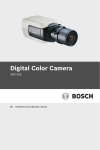
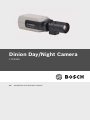
Dinion Day/Night Camera
LTC0465
en
Installation and Operation manual
Dinion Day/Night Camera
Table of Contents | en
3
Table of Contents
1
Safety
5
1.1
Safety precautions
5
1.2
Important safety instructions
6
1.3
Important notices
7
1.4
FCC & ICES compliance
1.5
UL certification
10
1.6
Bosch notices
11
8
2
Introduction
12
2.1
Features
12
2.2
Unpacking
12
3
Connections
13
3.1
Power connection
13
3.1.1
Low voltage cameras
13
3.1.2
High voltage cameras
14
3.2
Video connection
14
3.2.1
Output Video signal
14
3.3
Alarm and relay connector
15
3.4
Lens mounting
16
3.5
Back focus adjustment
17
3.6
Mounting the camera
19
3.7
Day/Night switching
19
4
Configuration
20
4.1
Menus
20
4.1.1
Top level menus
20
4.1.2
Menu navigation
20
4.2
Camera control communication (Bilinx)
21
4.3
Main menu structure
22
4.3.1
Shutter/AGC submenu
23
4.3.2
Day/Night submenu
24
4.3.3
Color submenu
25
Bosch Security Systems
Installation and Operation manual
F.01U.163.823 | v1.0 | 2010.01
4
en | Table of Contents
Dinion Day/Night Camera
4.3.4
VMD submenu (remotely via Bilinx only)
25
4.4
Install menu structure
27
4.4.1
Lens Wizard submenu
27
4.4.2
Alarm submenu
29
4.4.3
Defaults submenu
30
5
Technical Data
31
5.1
Specifications
31
Glossary
33
F.01U.163.823 | v1.0 | 2010.01
Installation and Operation manual
Bosch Security Systems
Dinion Day/Night Camera
Safety | en
1
Safety
1.1
Safety precautions
5
DANGER!
High risk: This symbol indicates an imminently hazardous
situation such as "Dangerous Voltage" inside the product.
If not avoided, this will result in an electrical shock, serious
bodily injury, or death.
WARNING!
Medium risk: Indicates a potentially hazardous situation.
If not avoided, this could result in minor or moderate bodily
injury.
CAUTION!
Low risk: Indicates a potentially hazardous situation.
If not avoided, this could result in property damage or risk of
damage to the unit.
NOTICE!
This symbol indicates information or a company policy that
relates directly or indirectly to the safety of personnel or
protection of property.
Bosch Security Systems
Installation and Operation manual
F.01U.163.823 | v1.0 | 2010.01
6
en | Safety
1.2
Dinion Day/Night Camera
Important safety instructions
Read, follow, and retain for future reference all of the following
safety instructions. Heed all warnings on the unit and in the
operating instructions before operating the unit.
1.
Cleaning - Generally, using a dry cloth for cleaning is
sufficient but a moist, fluff-free cloth or leather shammy
may also be used. Do not use liquid cleaners or aerosol
cleaners.
2.
Heat Sources - Do not install the unit near any heat
sources such as radiators, heaters, stoves, or other
equipment (including amplifiers) that produce heat.
3.
Water - Never spill liquid of any kind on the unit.
4.
Lightning - Take precautions to protect the unit from
power and lightning surges.
5.
Controls adjustment - Adjust only those controls specified
in the operating instructions. Improper adjustment of
other controls may cause damage to the unit.
6.
Power sources - Operate the unit only from the type of
power source indicated on the label.
7.
Servicing - Unless qualified, do not attempt to service this
unit yourself. Refer all servicing to qualified service
personnel.
8.
Replacement parts - Use only replacement parts specified
by the manufacturer.
9.
Installation - Install in accordance with the manufacturer's
instructions and in accordance with applicable local codes.
10. Attachments, changes or modifications - Only use
attachments/accessories specified by the manufacturer.
Any change or modification of the equipment, not
expressly approved by Bosch, could void the warranty or,
in the case of an authorization agreement, authority to
operate the equipment.
F.01U.163.823 | v1.0 | 2010.01
Installation and Operation manual
Bosch Security Systems
Dinion Day/Night Camera
1.3
Safety | en
7
Important notices
Disposal - Your Bosch product was developed and
manufactured with high-quality material and components that
can be recycled and reused. This symbol means that
electronic and electrical appliances, which have reached the
end of their working life, must be collected and disposed of
separately from household waste material. Separate collecting
systems are usually in place for disused electronic and
electrical products. Please dispose of these units at an
environmentally compatible recycling facility, per European
Directive 2002/96/EC
WARNING!
Power disconnect for high voltage versions: A unit has power
supplied whenever the power cord is inserted into the power
source. The power cord plug is the main power disconnect for
the unit. For pluggable equipment, install the socket outlet near
the equipment so it is easily accessible.
WARNING!
All-pole power switch: Incorporate an all-pole power switch,
with a contact separation of at least 3 mm in each pole, into the
electrical installation of the building.
CAUTION!
Fuse rating: The branch circuit protection must be secured with
a maximum fuse rating of 16 A. This must be in accordance with
NEC800 (CEC Section 60).
CAUTION!
The Low Voltage power supply unit must comply with EN/UL
60950. The power supply must be a SELV-LPS unit or a SELV Class 2 unit (Safety Extra Low Voltage - Limited Power Source).
Bosch Security Systems
Installation and Operation manual
F.01U.163.823 | v1.0 | 2010.01
8
en | Safety
1.4
Dinion Day/Night Camera
FCC & ICES compliance
FCC & ICES Information
(U.S.A. and Canadian Models Only)
This equipment has been tested and found to comply with the
limits for a Class B digital device, pursuant to part 15 of the
FCC Rules. These limits are designed to provide reasonable
protection against harmful interference in a residential
installation. This equipment generates, uses, and can radiate
radio frequency energy and, if not installed and used in
accordance with the instructions, may cause harmful
interference to radio communications. However, there is no
guarantee that interference will not occur in a particular
installation. If this equipment does cause harmful interference
to radio or television reception, which can be determined by
turning the equipment off and on, the user is encouraged to try
to correct the interference by one or more of the following
measures:
–
reorient or relocate the receiving antenna;
–
increase the separation between the equipment and
receiver;
–
connect the equipment into an outlet on a circuit different
from that to which the receiver is connected;
–
consult the dealer or an experienced radio/TV technician
for help.
Intentional or unintentional modifications, not expressly
approved by the party responsible for compliance, shall not be
made. Any such modifications could void the user's authority to
operate the equipment. If necessary, the user should consult
the dealer or an experienced radio/television technician for
corrective action.
The user may find the following booklet, prepared by the
Federal Communications Commission, helpful: How to Identify
and Resolve Radio-TV Interference Problems. This booklet is
available from the U.S. Government Printing Office,
Washington, DC 20402, Stock No. 004-000-00345-4.
F.01U.163.823 | v1.0 | 2010.01
Installation and Operation manual
Bosch Security Systems
Dinion Day/Night Camera
Safety | en
9
Informations FCC et ICES
(modèles utilisés aux États-Unis et au Canada uniquement)
Suite à différents tests, cet appareil s'est révélé conforme aux
exigences imposées aux appareils numériques de classe B, en
vertu de la section 15 du règlement de la Commission fédérale
des communications des États-Unis (FCC), et en vertu de la
norme ICES-003 d'Industrie Canada. Ces exigences visent à
fournir une protection raisonnable contre les interférences
nuisibles lorsque l'appareil est utilisé dans le cadre d'une
installation résidentielle. Cet appareil génère, utilise et émet
de l'énergie de radiofréquences et peut, en cas d'installation ou
d'utilisation non conforme aux instructions, engendrer des
interférences nuisibles au niveau des radiocommunications.
Toutefois, rien ne garantit l'absence d'interférences dans une
installation particulière. Il est possible de déterminer la
production d'interférences en mettant l'appareil
successivement hors et sous tension, tout en contrôlant la
réception radio ou télévision. L'utilisateur peut parvenir à
éliminer les interférences éventuelles en prenant une ou
plusieurs des mesures suivantes:
–
Modifier l'orientation ou l'emplacement de l'antenne
réceptrice;
–
Éloigner l'appareil du récepteur;
–
Brancher l'appareil sur une prise située sur un circuit
différent de celui du récepteur;
–
Consulter le revendeur ou un technicien qualifié en radio/
télévision pour obtenir de l'aide.
Toute modification apportée au produit, non expressément
approuvée par la partie responsable de l'appareil, est
strictement interdite. Une telle modification est susceptible
d'entraîner la révocation du droit d'utilisation de l'appareil.
La brochure suivante, publiée par la Commission fédérale des
communications (FCC), peut s'avérer utile : How to Identify and
Resolve Radio-TV Interference Problems (Comment identifier et
résoudre les problèmes d’interférences de radio et de télévision).
Cette brochure est disponible auprès du U.S. Government
Bosch Security Systems
Installation and Operation manual
F.01U.163.823 | v1.0 | 2010.01
10
en | Safety
Dinion Day/Night Camera
Printing Office, Washington, DC 20402, États-Unis, sous la
référence n° 004-000-00345-4.
1.5
UL certification
Disclaimer
Underwriter Laboratories Inc. ("UL") has not tested the
performance or reliability of the security or signaling aspects of
this product. UL has only tested fire, shock and/or casualty
hazards as outlined in UL's Standard(s) for Safety for Closed
Circuit Television Equipment, UL 2044. UL Certification does not
cover the performance or reliability of the security or signaling
aspects of this product.
UL MAKES NO REPRESENTATIONS, WARRANTIES, OR
CERTIFICATIONS WHATSOEVER REGARDING THE
PERFORMANCE OR RELIABILITY OF ANY SECURITY OR
SIGNALING RELATED FUNCTIONS OF THIS PRODUCT.
Disclaimer
Underwriter Laboratories Inc. ("UL") has not tested the
performance or reliability of the security or signaling aspects of
this product. UL has only tested fire, shock and/or casualty
hazards as outlined in UL's Standard(s) for Safety for Information
Technology Equipment, UL 60950-1. UL Certification does not
cover the performance or reliability of the security or signaling
aspects of this product.
UL MAKES NO REPRESENTATIONS, WARRANTIES, OR
CERTIFICATIONS WHATSOEVER REGARDING THE
PERFORMANCE OR RELIABILITY OF ANY SECURITY OR
SIGNALING-RELATED FUNCTIONS OF THIS PRODUCT.
F.01U.163.823 | v1.0 | 2010.01
Installation and Operation manual
Bosch Security Systems
Dinion Day/Night Camera
1.6
Safety | en
11
Bosch notices
Copyright
This manual is the intellectual property of Bosch Security
Systems and is protected by copyright. All rights reserved.
Trademarks
All hardware and software product names used in this
document are likely to be registered trademarks and must be
treated accordingly.
Note:
This manual has been compiled with great care and the
information it contains has been thoroughly verified. The text
was complete and correct at the time of printing. The ongoing
development of the products may mean that the content of the
user guide can change without notice. Bosch Security Systems
accepts no liability for damage resulting directly or indirectly
from faults, incompleteness or discrepancies between the user
guide and the product described.
More information
For more information please contact the nearest Bosch Security
Systems location or visit www.BoschSecurity.com
Bosch Security Systems
Installation and Operation manual
F.01U.163.823 | v1.0 | 2010.01
12
en | Introduction
Dinion Day/Night Camera
2
Introduction
2.1
Features
The Dinion Day/Night is a professional surveillance day/night
camera that incorporates 10-bit digital signal processing. The
Dinion Day/Night camera is easy to install and ready to use, and
offers good quality picture performance.
Features include:
2.2
–
Day/Night camera with mechanically switching IR filter
–
Bilinx™ bi-directional coaxial communications
–
Enhanced video motion detection
–
Backlight compensation
–
Lens autodetection
–
Lens wizard for easy backfocus
–
Alarm input and relay output
Unpacking
Unpack carefully and handle the equipment with care.
The packaging contains:
–
Dinion Day/Night camera
–
CCD protection cap (mounted on camera)
–
Spare lens connector (male)
–
These instructions
If equipment has been damaged during shipment, repack it in
the original packaging and notify the shipping agent or supplier.
WARNING!
Installation should only be performed by qualified service
personnel in accordance with the National Electrical Code or
applicable local codes.
CAUTION!
The camera module is a sensitive device and must be handled
carefully.
F.01U.163.823 | v1.0 | 2010.01
Installation and Operation manual
Bosch Security Systems
Dinion Day/Night Camera
3
Connections | en
13
Connections
CAUTION!
Before proceeding, disconnect the power from the power
supply cable. Ensure that the voltage of the unit matches the
voltage and type of the power supply being used.
3.1
Power connection
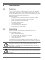
3.1.1
Low voltage cameras
VIDEO
12 VDC
24 VAC
ALARM
10 mm
Figure 3.1 Low voltage power connection
Connect power from a 24 VAC or 12 VDC class 2 power supply
as follows:
–
Use AWG16 to 22 stranded wire or AWG16 to 26 solid
–
Push in the tabs and insert the wires.
wire; cut back 5 mm (0.2 in) of insulation.
Note
These connections are not polarity sensitive.
Bosch Security Systems
Installation and Operation manual
F.01U.163.823 | v1.0 | 2010.01
14
en | Connections
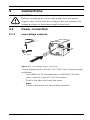
3.1.2
Dinion Day/Night Camera
High voltage cameras
VIDEO
ALARM
Figure 3.2
High voltage power connection
Connect the power cable of a high voltage camera to either a
230 VAC or a 120 VAC power supply outlet depending on the
version.
3.2
Video connection
VIDEO
Video BNC
ALARM
Figure 3.3
3.2.1
BNC connectors
Output Video signal
The camera has a BNC connector to connect the video coax
cable with a male BNC connector.
F.01U.163.823 | v1.0 | 2010.01
Installation and Operation manual
Bosch Security Systems
Dinion Day/Night Camera
3.3
Connections | en
15
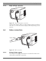
Alarm and relay connector
ALARM
5 mm
(0.2 in)
1
4
Figure 3.4 Alarm and relay connector pins
Pin
Alarm socket
1
Alarm in ground
2
Alarm in
3
Relay out contact 1
4
Relay out contact 2
–
Max. wire diameter AWG 22-28 for both stranded and
–
Default relay position normally open (n.o.); no alarm.
–
Alarm output relay switching capability: Max voltage 30VAC
solid; cut back 5 mm (0.2 in) of insulation.
or +40 VDC. Max 0.5 A continuous, 10 VA.
–
Alarm in: TTL logic, +5V nominal, +40 VDC max, DC coupled
–
Alarm in: configurable as active low or active high.
–
Max. 42 V allowed between camera ground and each of the
with 22 kOhm pull-up to +3.3 V.
relay pins.
Bosch Security Systems
Installation and Operation manual
F.01U.163.823 | v1.0 | 2010.01
16
en | Connections
3.4
Dinion Day/Night Camera
Lens mounting
The camera accepts CS-mount lenses. C-mount lenses can be
mounted using a lens adapter ring. DC-iris lenses are
recommended for the best picture performance. The camera
automatically detects the type of lens used and optimizes
performance accordingly. A spare male lens connector is
provided.
CAUTION!
To avoid damaging the CCD sensor when using a C-mount lens,
make sure a lens adapter ring (not included) is mounted onto
the camera before mounting the lens.
Lenses weighing more than 0.5 kg (1.1lbs) must be separately
supported.
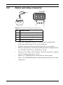
Bosch
Bosch
Figure 3.5 Mounting a lens
Figure 3.6 Lens connector
Pin
Video iris lens
DC iris lens
1
Supply (11.5V ±0.5, 50mA max.)
Damp -
2
Not used
Damp +
3
Video signal 1Vpp 1kOhm
Drive +
4
Ground
Drive -
Note
If a short circuit is detected on the lens connector, the onscreen display (OSD) failure message LENS SHORT CIRCUIT is
shown. The lens circuit is automatically disabled to avoid
internal damage. Remove the lens connector and check the pin
connections.
F.01U.163.823 | v1.0 | 2010.01
Installation and Operation manual
Bosch Security Systems
Dinion Day/Night Camera
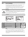
3.5
Connections | en
17
Back focus adjustment
To optimize picture sharpness in both bright and low-level
lighting, adjust the back focus. Use the camera's unique Lens
Wizard. This ensures that the object of interest always remains
in focus, even when focusing at the maximum lens iris opening
(for example, at night).
–
When back focusing varifocal lenses, adjust to obtain a
sharp picture in both wide-angle and tele positions for
both far and near focus.
–
When back focusing zoom lenses, ensure the object of
interest remains in focus throughout the entire zoom range
of the lens.
To adjust back focus:
1.
Open the slide door panel at the side of the camera.
Bos
ch
1.
2.
Unlock the back focus locking button.
Press and hold the center key for more than 1 second until
the Install menu appears.
3.
Select Wizard and move cursor to the Set Back Focus
Now item.
4.
Turn the back focus adjustment as required.
Bosch Security Systems
Installation and Operation manual
F.01U.163.823 | v1.0 | 2010.01
18
en | Connections
Dinion Day/Night Camera
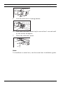
Bosch
5.
Lock the back focus locking button.
Bosch
6.
Press and hold the center key for more than 1 second until
all the menus disappear.
7.
Close the side door panel.
Note:
To backfucus a zoom lens, see the zoom lens installation guide.
F.01U.163.823 | v1.0 | 2010.01
Installation and Operation manual
Bosch Security Systems
Dinion Day/Night Camera
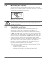
3.6
Connections | en
19
Mounting the camera
The camera can be mounted either from the top or from the
bottom (1/4" 20 UNC thread). The bottom mounting is isolated
from ground to prevent ground loops.
Figure 3.7 Mounting a camera
CAUTION!
Do not point the camera/lens into direct sunlight as this may
damage the sensors.
3.7
Day/Night switching
The camera is equipped with a motorized IR filter. The
mechanical IR filter can be removed in low-light or IR
illuminated applications by software configuration settings.
If Auto switching mode is selected, the camera automatically
switches the filter depending on the observed light level. The
switching level is programmable. In Auto switching mode the
camera prioritizes motion (the camera gives sharp images
without motion blur as long as the light level permits) or color
(the camera gives color pictures as long as the light level
permits). The camera recognizes IR illuminated scenes to
prevent unwanted switching to color mode.
There are three different methods of controlling the IR filter:
–
via an alarm input,
–
via Bilinx communication, or
–
automatically, based on the observed light levels.
Bosch Security Systems
Installation and Operation manual
F.01U.163.823 | v1.0 | 2010.01
20
en | Configuration
4
Dinion Day/Night Camera
Configuration
The camera normally provides an optimal picture without the
need for further adjustments. However, advanced set-up
options are available in a menu system for getting the best
results under special circumstances.
The camera implements your changes immediately so that
before and after settings are easily compared.
4.1
Menus
4.1.1
Top level menus
There are two upper level menus: a Main menu and an Install
menu. The menus have functions that can be selected directly
or submenus for more detailed set-up.
–
To access the Main menu, press the menu/select button
(center) for less than 1 second. The Main menu appears on
the monitor. Select and set-up the picture enhancement
functions. If not satisfied with your changes, recall the
default values.
–
The camera also has an Install menu in which the
installation settings can be set. To access the Install menu,
press the menu/select button (center) for longer than 2
seconds.
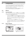
4.1.2
Menu navigation
Five keys, located behind the side door panel, are used for
navigating through menu system.
Bos
ch
Bosch
Figure 4.1 Side panel door
F.01U.163.823 | v1.0 | 2010.01
Figure 4.2 Menu/select key
Installation and Operation manual
Bosch Security Systems
Dinion Day/Night Camera
Configuration | en
21
Up key
Menu/Select key (center)
Right key
Figure 4.3 Navigation
Down key
Left key
–
Use the up or down keys to scroll through a menu.
–
Use the left or right keys to move through options or to set
–
When in a menu, quickly double-press the menu/select key
parameters.
to restore the selected item to its factory default.
–
To close all menus at once hold down the menu/select key
until the menu display disappears or continually select the
Exit item.
Some menus automatically close after about two minutes; other
menus have to be closed manually.
4.2
Camera control communication (Bilinx)
This camera is equipped with a coaxial communications
transceiver (also referred to as Bilinx). In combination with VPCFGSFT, the camera setting can be changed from any point
along the coaxial cable. All menus can be accessed remotely
giving full control of the camera. With this method of
communication it is also possible to disable the local keys on
the camera.To avoid loss of communication on an installed
camera, the COMM On/Off selection is not available while
using remote control. This function can only be accessed with
the camera buttons. Bilinx communications can only be
disabled using the buttons on the camera.
Disabled camera buttons
When the Bilinx communications link is active, the buttons on
the camera are disabled.
Bosch Security Systems
Installation and Operation manual
F.01U.163.823 | v1.0 | 2010.01
22
en | Configuration
4.3
Dinion Day/Night Camera
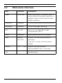
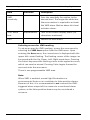
Main menu structure
Item
Selection
Level
-15 to +15
Description
Video level control: A positive value is
more useful for low-light conditions; a
negative value is more useful for very
bright conditions.
Shut/AGC
Submenu
Picture enhancement and performance
Day/Night
Submenu
Control day/night switching
BLC
On, Off,
Set to On to enable Back Light
Compensation (BLC)
Color
Sync
Submenu
White balance and color rendition
Internal
Internal - for free running camera
Line lock
operation.
Line lock - to lock to the AC power
supply
Vphase
0, 2 . . . 358
Adjusts the vertical phase
(only available if sync = line lock).
Exit
F.01U.163.823 | v1.0 | 2010.01
Exit the menu
Installation and Operation manual
Bosch Security Systems
Dinion Day/Night Camera
4.3.1
Configuration | en
23
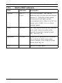
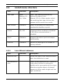
Shutter/AGC submenu
Item
Selection
Description
Shutter
AES, FL,
AES (auto-shutter) - the camera
Fixed
automatically sets the optimum shutter
speed. FL - flickerless mode avoids
interference from light sources
(recommended for video-iris or DC-iris
lenses only). FIXED - forces a fixed
shutter speed.
Gain
On, Off
On - the camera automatically sets the
gain to the lowest possible value
needed to maintain a good picture.
Off - sets AGC off.
Autoblack
On, Off
Autoblack On automatically increases
the visibility of details even when
scene contrast is less than full-range
due to mist, fog, etc.
EXIT
Bosch Security Systems
Returns to main menu.
Installation and Operation manual
F.01U.163.823 | v1.0 | 2010.01
24
en | Configuration
4.3.2
Dinion Day/Night Camera
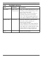
Day/Night submenu
Item
Selection
Description
Day/Night
Auto, Color,
Auto - the camera switches the IR cut-
Monochrome
off filter on and off depending on the
scene illumination level.
Monochrome - the IR cut-off filter is
removed, giving full IR sensitivity.
Color - the camera always produces a
color signal regardless of light levels.
Switch level
-15 to +15
Sets the video level in Auto mode at
which the camera switches to
monochrome operation.
A low (negative) value means that the
camera switches to monochrome at a
lower light level. A high (positive) value
means that the camera switches to
monochrome at a higher light level.
EXIT
F.01U.163.823 | v1.0 | 2010.01
Returns to main menu.
Installation and Operation manual
Bosch Security Systems
Dinion Day/Night Camera
4.3.3
Configuration | en
25
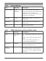
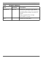
Color submenu
Item
Selection
Description
White balance
ATW,
ATW - Auto tracking white balance
AWBhold
allows the camera to constantly adjust
for optimal color reproduction.
AWBhold - Puts the ATW on hold and
saves the color settings.
Red gain
-5 to +5
Adjusts the Red gain to optimize the
white point.
Blue gain
-5 to +5
Adjusts the B gain to optimize the
white point.
EXIT
4.3.4
Returns to main menu.
VMD submenu (remotely via Bilinx only)
Item
Selection
Description
VMD
Off, Silent,
Off - Video Motion Detection (VMD) is
OSD
off.
Silent - video motion generates silent
alarm.
OSD - video motion generates onscreen text message alarm.
VMD area
Submenu
Select to enter the area set-up menu to
define the detection area.
Motion
Indicates the peak of measured motion
indicator
in the selected area. Press either the
right, left or center navigation button
to reset.
Bosch Security Systems
Installation and Operation manual
F.01U.163.823 | v1.0 | 2010.01
26
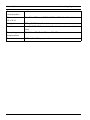
en | Configuration
Item
Dinion Day/Night Camera
Selection
Description
VMD
Sets the sensitivity for motion to the
sensitivity
desired level. The longer the white bar,
the more motion is required to acitvate
the VMD alarm. Motion above this level
activates alarm.
OSD alarm
Alphanumeric
Text for on-screen display alarm (16
text
characters maximum).
EXIT
Returns to main menu.
Selecting an area for VMD masking
To set-up an area for VMD masking, access the area menu by
selecting the VMD Area option from the VMD menu. Upon
entering the Area menu, the current area is displayed with the
upper left corner flashing. The flashing corner of the image can
be moved with the Up, Down, Left, Right arrow keys. Pressing
the Select key moves the flashing cursor to the opposite corner,
which can now be moved. Pressing Select again freezes the
area and exits the area menu.
There is one programmable VMD area.
Note:
When VMD is enabled, normal light fluctuations or
environmental factors can contribute to false-positive alarms.
Because of this, it is recommended to not connect the VMDtriggered alarm output of the camera to a monitored alarm
system, as the false-positive alarms may be considered a
nuisance.
F.01U.163.823 | v1.0 | 2010.01
Installation and Operation manual
Bosch Security Systems
Dinion Day/Night Camera
4.4
Configuration | en
27
Install menu structure
Item
Lens type
Selection
Description
Auto,
Auto: - the camera automatically
Manual, DC-
selects the type of lens.
iris, Video
Manual, DC-iris, Video modes: select
the matching lens type to force the
camera to the correct lens mode.
Lens Wizard
Submenu
Select to optimize the camera-lens
combination backfocus point.
Comm
On, Off
Communications enabled or disabled.
If Off, Bilinx communication is
disabled.
Alarm
Submenu
Program the alarm input and output
functionality.
Defaults
Submenu
Returns all settings for all modes to
factory defaults
4.4.1
Lens Wizard submenu
Item
Detected lens
Selection
Description
Shows the type of lens detected when
auto lens detection is used.
Set Backfocus
Select to fully open the iris. Follow the
now
instructions below for setting the
backfocus for your particular lens type.
After focusing the object of interest
remains in focus under bright and low
light conditions.
Bosch Security Systems
Installation and Operation manual
F.01U.163.823 | v1.0 | 2010.01
28
en | Configuration
Item
Dinion Day/Night Camera
Selection
Set LVL
Description
Only for video-iris lenses.
Adjust the level control on the lens to
center the level detector indicator (see
below).
EXIT
Returns to Install menu.
Adjustment procedure DC-iris Lens
1.
Unlock the back focus locking button.
2.
Access the Lens Wizard menu.
3.
Set Back Focus Now is highlighted in the menu.
4.
Turn the back focus adjustment as required.
5.
Lock the back focus locking button.
6.
Exit the menu.
Adjustment procedure Manual-iris Lens
1.
Unlock the back focus locking button.
2.
Adjust the lens to the maximum lens opening.
3.
Turn the back focus adjustment as required.
4.
Lock the back focus locking button.
5.
Adjust lens opening to suit scene.
Adjustment procedure Video-iris Lens
1.
Unlock the back focus locking button.
2.
Access the Lens Wizard menu.
3.
Set Back Focus Now is highlighted in the menu.
4.
Turn the back focus adjustment as required.
5.
Lock the back focus locking button.
6.
Select Set LVL in the menu; the Level bar appears.
7.
Point the camera at the scene it will be mostly viewing.
8.
Adjust the level potentiometer located on the lens until the
Level bar is in the central position.
9.
Exit the menu.
F.01U.163.823 | v1.0 | 2010.01
Installation and Operation manual
Bosch Security Systems
Dinion Day/Night Camera
4.4.2
Configuration | en
29
Alarm submenu
Item
Selection
Description
Alarm In -
None, high,
Select none to disable the alarm input.
Active
low
Select active-high or active-low for the
alarm input connector.
Alarm In -
None,
Selects the action of the camera when
Action
Mono
the alarm input is active.
Alarm out -
VMD,
VMD: - output relay activates on VMD
Action
Remote,
alarms.
Day/Night,
Remote: - make the output relay
Filter move
available to remote communication
devices.
Day/Night: - output relay activates
when camera is in monochrome mode.
Filter move: - output relay activates
just before the IR filter starts moving
and de-activates when video level has
stabilized (2 to 3 seconds)
Alarm out -
Normally
Relay
open,
Select how the output relay activates.
Normally
closed
EXIT
Bosch Security Systems
Returns to Install menu.
Installation and Operation manual
F.01U.163.823 | v1.0 | 2010.01
30
en | Configuration
4.4.3
Dinion Day/Night Camera
Defaults submenu
Item
Selection
Description
Restore All
No, Yes
Restores all settings to their default
(factory) values. Select YES, then press
the Menu/Select button to restore all
values.
When completed the message
RESTORED! is shown.
EXIT
F.01U.163.823 | v1.0 | 2010.01
Returns to Install menu.
Installation and Operation manual
Bosch Security Systems
Dinion Day/Night Camera
Technical Data | en
5
Technical Data
5.1
Specifications
31
Type number
LTC0465/11
LTC0465/21
LTC0465/51
LTC0465/61
Standard
PAL
NTSC
PAL
NTSC
Active pixels
752 x 582
768 x 494
752 x 582
768 x 494
Rated supply
+12 VDC
+12 VDC
230 VAC
120 VAC
voltage
24 VAC
24 VAC
50 Hz
60 Hz
(50 Hz)
(60 Hz)
Minimum
<0.26 lux
illumination
<0.06 lux (in monochrome mode)
All versions
Imager
1/3-inch Interline CCD
Resolution
540 TVL
SNR
> 50 dB
Video output
1 Vpp, 75 Ohm
Synchroniza-
Internal, Line Lock selectable
tion
Shutter
AES (1/60 [1/50] to 1/150000) automatic
flickerless, fixed selectable
Day/Night
Color, Mono, Auto
AGC
AGC On (20 dB) or Off (0 dB) selectable
Back Light
One area, center-weighted
Compensation
(BLC)
White Balance
ATW, AWBhold (2500 to 10000K)
Lens mount
CS compatible, C-mount compatible with adapter ring
ALC lens
Video or DC iris auto detect
Video Motion
One area, fully programmable remotely
Detection
(VMD)
Communication
Bosch Security Systems
Two-way Bilinx (bi-directional)
Installation and Operation manual
F.01U.163.823 | v1.0 | 2010.01
32
en | Technical Data
Power
Dinion Day/Night Camera
<4 W
consumption
Dimensions
58 x 66 x 122 mm (2.28 x 2.60 x 4.80 in) without lens
(H x W L)
Weight
450 g (0.99 lb) without lens
Tripod mount
Two 1/4" 20 UNC - isolated (bottom) and non-isolated
(top)
Operating
-20 °C to +55 °C (-4 °F to +131 °F)
temperature
Controls
OSD with softkey operation
F.01U.163.823 | v1.0 | 2010.01
Installation and Operation manual
Bosch Security Systems
Dinion Day/Night Camera
Glossary | en
33
Glossary
A
AES
Automatic Electronic Shutter (see Electronic iris).
Aperture
The size of the opening in the lens iris that controls the amount
of light reaching the CCD Sensor. The larger the F-number, the
less light reaches the sensor. An increase of one F-stop, halves
the amount of light reaching the sensor.
Auto Level Control (ALC)
The adjustment of the video level to give the desired brightness
level. This can be done electronically or by means of an iris
control.
Auto White Balance (AWB)
A feature that allows a color camera to automatically adjust its
output color to give a natural color, independent of the lighting
used.
AutoBlack
A technique of boosting the video signal level to produce a full
amplitude video signal, even when the scene contrast is less
than full range (glare, fog, mist, etc.).
AutoIris
The lens iris opening is automatically adjusted to allow the
correct illumination of the camera sensor. With a direct drive
(DC) iris lens, the camera controls the aperture size. A video iris
lens has the control circuit in the lens itself.
Automatic Gain Control (AGC)
The electronics that regulate the gain or amplification of the
video signal. AGC is used in low-light conditions with the iris
fully open.
B
Back Light Compensation (BLC)
Selectively amplifies parts of the image to compensate for large
Bosch Security Systems
Installation and Operation manual
F.01U.163.823 | v1.0 | 2010.01
34
en | Glossary
Dinion Day/Night Camera
contrast differences when only a portion of the image is brightly
lit (e.g. a person in a sunlit doorway). See also Smart BLC.
Backfocus
The distance between the image plane and the rear portion of
the lens. Correct backfocus adjustment ensures that the
camera remains in focus under various conditions.
Bilinx
A communications protocol that allows remote control,
configuration, and updates to be performed over the video
cable (Coax or Passive UTP).
Bilinx address
The address may be set locally using the Bilinx Configuration
Tool for Imaging Devices (CTFID).
C
CCD Format
Indicates the size of the camera sensor used. In general, the
larger the sensor, the more sensitive the camera and the better
the image quality. The format is quoted in inches, for example
1/3 or 1/2 inch.
Charged Coupled Device (CCD)
A CCD is a type of solid state image sensor used in CCTV
cameras. The sensor converts light energy into electrical
signals.
Color Temperature
A measure of the relative color of illumination. Generally used
to specify the color balance correction of a camera to achieve a
natural color image.
D
Day/Night (infrared sensitive)
A camera that has normal color operation in situations where
there is sufficient illumination (day conditions), but where the
sensitivity can be increased when there is little light available
(night conditions). This is achieved by removing the infrared cut
filter required for good color rendition. The sensitivity can be
F.01U.163.823 | v1.0 | 2010.01
Installation and Operation manual
Bosch Security Systems
Dinion Day/Night Camera
Glossary | en
35
further enhanced by integrating a number of fields to improve
the signal-to-noise ratio of the camera (this may introduce
motion blur).
Default Shutter
A feature allowing the shutter speed to be set to a fast speed to
eliminate motion blur and provide a detailed and clear image of
fast-moving objects while there is sufficient light. When light
levels fall and other adjustments have been exhausted, the
shutter speed reverts to the standard setting to maintain
sensitivity.
Depth of Field
The distance from the nearest to the furthermost point that
appears in focus. The smaller the aperture, the greater the
depth of field.
Dynamic Noise Reduction (DNR)
A digital video processing technique that measures the noise
(image artifacts) in the picture and automatically reduces it.
E
Electronic iris
Electronic iris (or AES - Automatic Electronic Shutter) adjusts
the camera shutter speed to compensate for lighting changes.
In some cases this can eliminate the need for an autoiris lens.
F
F-Number
The standard measure of the lens aperture, which is the iris
diameter, divided by the focal length of the lens. The lower the
maximum aperture (F-Number or F-Stop), the more light that
passes through the lens.
F-Stop
See F-Number
Field of View
The measure of the visible area within the camera’s field of
view. The larger the focal length, the smaller the field of view.
The smaller the focal length, the wider the field of view.
Bosch Security Systems
Installation and Operation manual
F.01U.163.823 | v1.0 | 2010.01
36
en | Glossary
Dinion Day/Night Camera
Focal Length
The distance from the optical center of the lens to the image of
an object located at an infinite distance from the lens. Long
focal lengths give a small field of view (e.g. telephoto effect),
while short focal lengths give a wide angle view.
I
Infrared Illumination
Electromagnetic radiation (light) with a longer wavelength than
is visible to the human eye. IR illumination is prominent at dusk
and dawn and in incandescent lamps. IR illuminators come in
the form of lamps with the appropriate filters, LEDs, or lasers.
CCD sensors are less sensitive to IR than visible light, but IR
can significantly increase the total illumination level, leading to
a much better image at low light levels.
IRE (Institute of Radio Engineers)
A measurement of video amplitude that divides the area from
the bottom of sync to peak white level into 140 equal units 140 IRE equals 1V peak-to-peak. The range of active video is
100 IRE.
L
Lens wizard
The lens wizard is used when setting the backfocus. It opens
the iris fully while maintaining the correct video level using AES.
Lux
The international (SI) unit of measurement of the intensity of
light. It is equal to the illumination of a surface one meter away
from a single candle.
O
OSD
On-screen Display: Menus are shown on the display monitor.
F.01U.163.823 | v1.0 | 2010.01
Installation and Operation manual
Bosch Security Systems
Dinion Day/Night Camera
Glossary | en
37
P
Privacy Masking
The ability to mask out a specific area to prevent it from being
viewed in order to comply with privacy laws and particular site
requirements.
PWIE
Peak White Inverse Engine: White highlights are automatically
turned black to reduce bright spots. Useful in traffic and car
park applications.
R
Region of Interest
A specific area within a field of view, used by the motion
detection algorithm to identify motion.
Resolution
The measure of the fine detail that can be seen in an image. For
analog systems this is typically measured in horizontal
Television Lines or TVL. The higher the TVL rating, the higher
the resolution.
S
Saturation
The amplitude of the chrominance signal affecting the vividness
of the color.
Sensitivity
A measure of the amount of light required to provide a standard
video signal. Sensitivity values are stated in lux (see Lux).
SensUp (sensitivity up)
Increases camera sensitivity by increasing the integration time
on the CCD (lowering shutter time from 1/50 to 1/5 s). This is
accomplished by integrating the signal from a number of
consecutive video fields to reduce signal noise.
Signal-to-noise ratio
The ratio between a useful video signal and unwanted noise
measured in dB.
Bosch Security Systems
Installation and Operation manual
F.01U.163.823 | v1.0 | 2010.01
38
en | Glossary
Dinion Day/Night Camera
Smart BLC (Back Light Compensation)
Smart back-light compensation allows the camera to
automatically compensate for bright areas of a high contrast
scene without having to define a window or area.
U
UTP (Unshielded Twisted Pair)
A variant of twisted pair cabling, UTP cable is not surrounded
by any shielding. The wires in a twisted pair cable are twisted
around each other to minimize interference from the other
twisted pairs in the cable. UTP is the primary wire type for
telephone usage and the most commonly used type of
networking cable.
V
VMD
Video Motion Detection: An algorithm for motion detection in
which the camera compares the current image with a reference
image and counts the number of pixels that have changed
between the two images. An alarm is generated when the
number of pixel changes exceeds a user-configured threshold.
W
WDR (Wide Dynamic Range)
A cameras dynamic range is the difference between the
minimum and maximum acceptable signal levels. A scene with
both very low and very high illumination levels requires a
camera with a wide dynamic range to handle it correctly and
produce a useful image.
F.01U.163.823 | v1.0 | 2010.01
Installation and Operation manual
Bosch Security Systems
Bosch Security Systems
www.BoschSecurity.com
© Bosch Security Systems, 2010