1
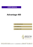
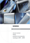
SiPass integrated
AFI5100
Installation manual
Fire Safety & Security Products
Siemens Building Technologies
Liefermöglichkeiten und technische Änderungen vorbehalten.
Data and design subject to change without notice. / Supply subject to availability.
© 2008 Copyright by
Siemens Building Technologies
Wir behalten uns alle Rechte an diesem Dokument und an dem in ihm dargestellten Gegenstand vor. Der Empfänger erkennt diese Rechte
an und wird dieses Dokument nicht ohne unsere vorgängige schriftliche Ermächtigung ganz oder teilweise Dritten zugänglich machen oder
außerhalb des Zweckes verwenden, zu dem es ihm übergeben worden ist.
We reserve all rights in this document and in the subject thereof. By acceptance of the document the recipient acknowledges these rights
and undertakes not to publish the document nor the subject thereof in full or in part, nor to make them available to any third party without our
prior express written authorization, nor to use it for any purpose other than for which it was delivered to him.
Contents
1
1.1
1.2
1.3
1.4
1.5
1.6
1.7
1.8
1.9
1.10
Input Point Module (AFI5100) ................................................................5
Product Description...................................................................................5
Product Numbers ......................................................................................5
Prerequisites .............................................................................................5
Expected Installation Time........................................................................5
Mounting Instructions................................................................................6
Wiring ........................................................................................................6
Links and Jumpers ....................................................................................9
LEDs .......................................................................................................10
Recommended Cable Specifications ......................................................11
Programming and Firmware Download ..................................................11
3
Siemens Building Technologies
Fire Safety & Security Products
11.2007
4
Siemens Building Technologies
Fire Safety & Security Products
11.2007
Input Point Module (AFI5100)
1
Input Point Module (AFI5100)
1.1
Product Description
The AFI5100 is an Input Point Module used as part of a Siemens integrated access
control and security solution. It provides an interface between an Advanced Access
Controller (ACC) and up to 32 input devices used to monitor a secure facility.
The AFI5100 continuously monitors the status of all input devices connected; for
example, Passive Infrared Detectors (PIRs). Any changes in state are instantly
communicated to the ACC and then on to the Host system if necessary.
1.2
Product Numbers
6FL7820-8CB10
1.3
AFI5100 – Input Point Module and base-plate
Prerequisites
z Input Devices to be connected to the IPM
z Cabling (RS-485)
z Required Tools & Materials
z Medium-duty drill and associated drill-bits (if required)
z 4 mounting screws or standoffs (approx. 4mm)
z Flat-blade terminal screwdriver
z Wire cutters
z Cable strippers
1.4
Expected Installation Time
30 minutes
5
Siemens Building Technologies
Fire Safety & Security Products
11.2007
Input Point Module (AFI5100)
1.5
Mounting Instructions
1.
Remove the AFI5100 from its carton and discard the packaging material.
2.
Place the AFI5100 (base-plate) against the surface to which it is to be affixed
and mark the location of the mounting holes.
3.
If being mounted within a cabinet, simply align the AFI5100 base-plate with
the holes located on the cabinet backplane and proceed to step 3.
4.
It is recommended that you affix the AFI5100 in all four of the mounting locations.
WARNING
1.6
Do not apply power to the IPM or associated components at this stage.
5.
Select the appropriate drill bit according to the mounting surface / hole size
and drill the holes in the locations marked (if required).
6.
Fasten the AFI5100 base-plate to the surface using the correct type of screws
or standoffs for the surface.
7.
Connect the cabling to the AFI5100 PCB (as described in the next section titled ‘Wiring’).
8.
Apply power to the AFI5100 and test its operation.
9.
This step may require installation and programming of the access control host
software and download of the firmware instruction set.
Alternatively, the firmware and configuration may be carried out using the FLN
Field Service Tool.
Wiring
It is recommended that you wear a grounding strap while carrying out this procedure.
1.
Connect all input devices to the INPUT ports.
Listed end-of-line resistors must be connected to the wiring for each input device if they are to be
supervised. If supervised, cable must be shielded and total cable run resistance must not exceed 100
Ohms. Cable shielding must be unconnected at the device end, and connected to the board earth at
the IPM end.
2.
Connect any devices to the OUTPUT ports.
3.
Connect appropriate wiring to the FIRE OVERRIDE INPUT port if required.
Listed end-of-line resistors must be connected to the Fire Over-ride Input wires if you are implementing Enhanced Fire Over-ride. Enhanced mode requires the connection of 22Kohm supervision resistor
circuits. Cable must be shielded and total cable run resistance must not exceed 100 Ohms.
4.
Connect the next device in the Fire Override sequence to the FIRE OVERRIDE OUTPUT port if required.
5.
Connect the FLN wires (from the ACC) to the RS485 BUS port.
6.
If the FLN cable is long or subject to high noise, ensure that the jumper across
link LK10 (EOL) has been made. This only applies to units located on the
ends of bus lines.
6
Siemens Building Technologies
Fire Safety & Security Products
11.2007
Input Point Module (AFI5100)
7.
Connect the active (+ve) and neutral (-ve) wires from the Power Supply Unit
(PSU) to the POWER IN port. Ensure the polarity of the connection is made
correctly.
8.
Check all connections thoroughly.
9.
Power can now be applied to the AFI5100 .The following diagram displays the
layout and dimensions of the AFI5100 with brace attached:
287mm (11.30")
9mm (0.35")
(0.35") 9mm
257mm (10.12")
5mm
(0.20")
IN+ ININ+
FIRE INPUT
IN+
INPUT 3
INPUT2
IN+
IN-
INPUT 5
IN-
IN-
IN+
IN-
IN+
IN-
INPUT 1
FOR NORMAL
LK1LK2
IN+
IN-
INPUT 7
INPUT 6
IN+
IN-
IN+
IN+
IN-
IN+
INPUT 9
INPUT 4
IN+
IN-
IN-
INPUT 13
INPUT 8
IN+
IN-
IN+
IN-
INPUT 10
INPUT 11
IN+
IN-
IN-
INPUT 15
INPUT 14
IN+
IN-
IN+
INPUT 12
IN+
IN+
IN-
INPUT 16
IN+
INPUT 18
IN+
IN-
INPUT 21
IN-
IN+
IN-
INPUT 17
IN-
INPUT 22
IN-
INPUT 19
IN-
IN+
INPUT 23
IN+
IN-
IN+
INPUT 20
IN+
IN-
INPUT 25
IN+
IN-
INPUT 24
IN+
IN+
IN-
IN-
IN+
INPUT 26
IN+
IN-
INPUT 30
INPUT 29
IN-
INPUT 27
IN-
INPUT 31
IN+
IN-
INPUT 28
IN+
IN-
INPUT 32
S/N:
FOR
FOR ENABLE
INPUT1
INPUT2
INPUT3
INPUT4
INPUT5
INPUT6
INPUT7
INPUT8
INPUT9
INPUT10
INPUT11
INPUT12
INPUT13
INPUT14
INPUT15
INPUT16
INPUT17
INPUT18
INPUT19
INPUT20
INPUT21
INPUT22
INPUT23
INPUT25
INPUT24
INPUT26
INPUT27
INPUT28
INPUT29
INPUT30
INPUT32
INPUT31
LK4LK6
LK3
LK7
LK8
LK11
250mm
(9.84")
OUTPUT1
OUTPUT3
OUTPUT2
OUTPUT4
LK 9
DC OUT 1
DC OUT 2
TX COMMS
RX COMMS
POWER
ACTIVITY
BRD - 00005
Siemens Building Technologies
LK5
LK12
LK13
LK14
FOR EN
FOR DIS
LK 10
RLY1
RS-485
E
-
+
RLY2
RLY3
LOCAL IN OUT
DC OUT
DC OUT
OUTPUT 4
OUTPUT 3 OUTPUT 2
IP+ IP- OP+ OP-
0V V+
0V V+
Nc C No
Nc C No
Nc C No
RLY4
RLY5
OUTPUT 1
FIRE OUT
POWER IN
Nc C No
Nc C No
0V V+ E
7
Siemens Building Technologies
Fire Safety & Security Products
11.2007
Input Point Module (AFI5100)
The following diagram displays the location of the ports on the AFI5100 :
1
3
2
IN+ ININ-
IN+
FOR IN
IN+
INPUT 1
IN-
IN+
INPUT 5
IN-
INPUT 6
IN-
IN+
INPUT2
IN-
IN+
FOR NORMAL
LK1 LK2
IN+
IN+
INPUT 4
IN-
INPUT 7
IN-
IN+
INPUT 3
IN+
IN-
INPUT 9
IN-
IN+
IN-
IN-
IN+
IN-
IN+
INPUT 13
INPUT 8
IN+
INPUT 10
IN+
INPUT 11
IN+
IN-
IN-
INPUT 15
INPUT 14
IN-
IN+
INPUT 12
IN+
IN-
IN+
INPUT 17
IN-
IN+
IN-
INPUT 21
INPUT 16
IN+
IN-
IN+
IN-
INPUT 18
INPUT 19
IN+
IN-
IN-
INPUT 23
INPUT 22
IN-
IN+
IN+
INPUT 20
IN+
IN-
IN+
INPUT 25
IN+
IN-
IN-
IN+
INPUT 29
INPUT 24
IN+
IN-
INPUT 26
IN-
IN+
IN-
IN-
INPUT 31
INPUT 30
IN+
INPUT 27
IN-
INPUT 28
IN+
IN-
INPUT 32
S/N:
FOR
FOR ENABLE
INPUT1
INPUT2
INPUT3
INPUT4
INPUT5
INPUT6
INPUT7
INPUT8
INPUT9
INPUT10
INPUT11
INPUT12
INPUT14
INPUT13
INPUT16
INPUT15
INPUT17
INPUT19
INPUT18
INPUT20
INPUT21
INPUT22
INPUT23
INPUT25
INPUT24
INPUT26
INPUT28
INPUT27
INPUT30
INPUT29
INPUT31
INPUT32
LK4 LK6
LK5
LK7
LK8
LK11
OUTPUT1
OUTPUT3
LK 9
OUTPUT2
OUTPUT4
DC OUT 1
DC OUT 2
TX COMMS
RX COMMS
POWER
ACTIVITY
BRD - 00005
Siemens Building Technologies
LK3
LK13
LK12
LK14
FOR EN
FOR DIS
LK 10
RLY1
RS-485
E
-
9
+
12V OUT 2 12V OUT 1
LOCAL IN OUT
IN+ IN- OUT+ OUT-
8
0V V+
0V V+
RLY2
OUT 4
OUT 3
Nc C No
Nc C No
7
RLY3
OUT 2
Nc C No
RLY4
RLY5
OUT 1
FOR OUT
DC POWER IN
Nc C No
Nc C No
0V V+ E
6
5
4
The following table provides a brief description of each port:
Port Name
Brief Description
1
INPUT 17 – INPUT 32
Input Ports 1 - 32
Inputs for connection to monitoring and input
devices
2
INPUT 1 – INPUT 16
Input Ports 1 - 16
Inputs for connection to monitoring and input
devices
3
FOR IN
Fire Over-ride Input Port
Input for Fire Over-ride wiring
4
DC Power IN
DC power input
5
FOR OUT
Fire Over-ride Output Port
Fire Over-ride for connecting devices in Fire Override sequence
6
OUT 1 – OUT 4
Output Ports 1 - 4
Auxiliary Relay-driven Outputs
7
12V OUT 1-12V OUT 2
Auxiliary 12 V DC Power Supply 1-2
12 V DC power source
8
LOCAL IN OUT
Tamper In/Out Port
Local input and output for tamper detection and
alarm
9
RS485 BUS
RS485 communications port for connection to an
ACC FLN channel
8
Siemens Building Technologies
Fire Safety & Security Products
11.2007
Input Point Module (AFI5100)
1.7
Links and Jumpers
The following table outlines the link settings for the AFI5100:
Value
LK1, LK2
Links 1 and 2 are used to configure
whether Fire Over-ride (FOR) will operate in Enhanced FOR mode or Normal.
To enable Normal
Mode:
If the links are set to the off position,
FOR input will have no effect on the
state of the output relays.
ENABLE
LK4 LK6
FOR operation
ignored:
LK4 LK6
FOR
If the links are set to FOR operation,
activation of the FOR input will cause
the outputs to return to the NO position.
FOR operation
active:
ENABLE
Links 4 and 6 control whether Fire
Over-ride (FOR) is enabled.
FOR
LK4, LK6
LK1 LK2
FOR
LK1 LK2
FOR
Enhanced mode also requires the
connection of a supervision circuit to
the Fire Over-ride Input.
To enable Enhanced Mode:
NORMAL
Description
NORMAL
Link
LK3, LK5
These auxiliary links have been included for further enhancement of the system.
LK7
LK7 affects the reset action when the
RESET link (LK9) is set and the power
turned on.
LK7
See LK9 below for a description of how
to reset the unit.
If the jumper on Link 7 is set as shown,
it is set to “Full Reset” mode.
LK7
If the jumper on Link 7 is taken off, it is
set to “Partial Reset” mode.
LK8
This is a General Purpose links that has been included for further enhancement
of the system.
LK9
Memory Clear and Reset
Setting LK9 and turning the power off and on will reset the IPM. A full or partial
reset can be achieved by setting LK7 on or off.
If LK7 is set, the IPM will fully reset and any firmware loaded into the memory will
be erased. You will need to re-program the IPM with firmware again before it can
operate.
If LK7 has the jumper removed, the microcontroller will be rebooted but the firmware will remain in memory.
LK10
EOL Termination (Bus)
This link allows the RS485 BUS communications channel to be terminated
in noisy or lengthy comms.
Note: Units located at the end of bus
lines only should have this link set.
LK11 – LK14
RS485 BUS port
not terminated.
Enabling Fire Override for a relay
means that when the FOR input is
activated, the relay output switch to the
NO position.
LK10
LK10
EOL
FOR Activation
These links allow FOR activation to be
enabled or disabled for each individual
relay output.
RS485 BUS port
terminated.
EOL
LK11
LK12
FOR EN
FOR DIS
In the above diagram LK11 (Relay 1) is
set to FOR Enabled and LK12
(Relay 2) is set to FOR Disabled.
9
Siemens Building Technologies
Fire Safety & Security Products
11.2007
Input Point Module (AFI5100)
1.8
LEDs
The following table describes the operation of the LEDs located on the AFI5100 :
LED
Brief Description
POWER
The POWER led is illuminated when power has been applied to the device.
ACTIVITY
The ACTIVITY led indicates that the AFI5100 is accessing information contained in its internal database or performing a routine operation.
This LED also indicates whether the initial instruction set has been downloaded.
If power is applied and the LED blinks quickly, the AFI5100 instruction set (firmware) needs to be downloaded. If the LED is blinking slowly, approximately
once per second, a firmware set has already been downloaded.
Tx COMMS
The Transmission COMMS LED flashes when the IPM is sending data to the
ACC to which it has been connected (via an FLN).
Rx COMMS
The Transmission COMMS LED flashes when the IPM is receiving data from
the ACC to which it has been connected (via an FLN).
Inputs
The tricolor Input Port LEDs indicate the current status of the input port. See the
table below for an explanation of the colors.
Outputs
Each Output Relay has a corresponding LED that is illuminated when the relay
is activated.
Fire
The Fire LED is illuminated when Fire Over-ride is activated.
Each input LED may be in one of two states as indicated by color.
LED Color
Input status
Fire Over-ride status
Green
Denotes input Normal: Closed
Denotes FOR Normal: Closed
Orange
Denotes input Normal: Open
Denotes FOR Normal: Open (alarm)
10
Siemens Building Technologies
Fire Safety & Security Products
11.2007
Input Point Module (AFI5100)
1.9
Recommended Cable Specifications
The following table outlines the cable recommended for connection of an integrated security system:
Communication
Type
RS485
RS232
RS422
RJ-45
RJ-12
Power
(12/24 V DC)
Recommended Cable Specifications
Core
Pairs
AWG
Stranding
Wire Type
Insulation
Shield
Jacket
4
2
28
7 x 36
Tinned
Copper
Polyethylene
Aluminium foil- Polyester tape
/ braided shield
PVC
6
3
28
7 x 36
Tinned
Copper
Polyethylene
Aluminium foil- Polyester tape
/ braided shield
PVC
8
4
28
7 x 36
Tinned
Copper
Polyethylene
Aluminium foil- Polyester tape
/ braided shield
PVC
4
2
24
7 x 32
Tinned
Copper
Polyethylene
Aluminium foil- Polyester tape
/ no braid
PVC
6
3
24
7 x 32
Tinned
Copper
Polyethylene
Aluminium foil- Polyester tape
/ no braid
PVC
8
4
24
7 x 32
Tinned
Copper
Polyethylene
Aluminium foil- Polyester tape
/ no braid
PVC
4
2
24
7 x 32
Tinned
Copper
Polyethylene
Aluminium foil- Polyester tape
/ no braid
PVC
6
3
24
7 x 32
Tinned
Copper
Polyethylene
Aluminium foil- Polyester tape
/ no braid
PVC
8
4
24
7 x 32
Tinned
Copper
Polyethylene
Aluminium foil- Polyester tape
/ no braid
PVC
8
4
24
Solid
Bare
Copper
Polyethylene
Unshielded
PVC
8
4
24
7 x 32
Tinned
Copper
Polyethylene
Unshielded
PVC
8
4
24
Solid
Bare
Copper
Polyethylene
Aluminium foil- Polyester tape
/ no braid
PVC
8
4
24
7 x 32
Tinned
Copper
Polyethylene
Aluminium foil- Polyester tape
/ no braid
PVC
2
1
18
19 x 30
Tinned
Copper
Polyethylene
Unshielded
PVC
The previous table provides a guideline for selecting an appropriate cable type only. Other cable types
are also compatible with the system and can be used to achieve the same results.
1.10
Programming and Firmware Download
The AFI5100 is programmed using the host software application via the ACC, or
using the FLN Configurator Field Service Tool application. Please refer to the appropriate User’s Guide for more Information.
Information in this document is based on specifications believed correct at the time of publication. The
right is reserved to make changes as design improvements are made.
11
Siemens Building Technologies
Fire Safety & Security Products
11.2007
Issued by
Siemens Building Technologies
Fire & Security Products GmbH & Co. oHG
D-76181 Karlsruhe
www.sbt.siemens.com
Document no.
A24205-A335-B245
Edition
11.2007
© 2008 Copyright by
Siemens Building Technologies
Data and design subject to change without notice.
Supply subject to availability.
Printed in the Federal Republic of Germany
on environment-friendly chlorine-free paper.