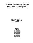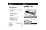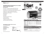
1
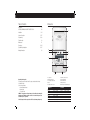
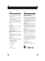
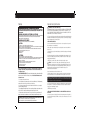
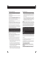
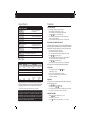
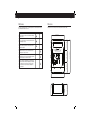
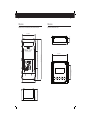
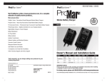
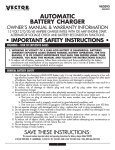
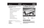
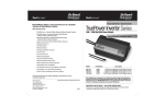
ProMar Digital
Performance Charging
ProMar Digital
Performance Charging
Visit ProMariner online at www.promariner.com, for a complete
selection of quality marine products...
Here are just a few:
ProMite Series - Recreational Grade Waterproof Marine Battery Chargers
ProSport Series - Heavy Duty Recreational Grade Waterproof
Marine Battery Chargers
ProTournament Series - Professional Grade Tournament
Waterproof Marine Battery Chargers
ProIsoCharge Series - Digitally Controlled Zero Loss Charging Isolators
Digital Mobile Charge In-Transit Chargers
Battery Maintainers
AC Plug Holders
Battery Isolators
Isolation Transformers
ProNauticP Series Instruction Manual
Galvanic Isolators and Monitored Systems
Models
Part No.
Corrosion Control Products
ProNautic1210P
ProNautic1215P
ProNautic1220P
ProNautic1230P
ProNautic1240P
ProNautic1250P
ProNautic1260P
ProNautic2420P
ProNautic2430P
63110
63115
63120
63130
63140
63150
63160
63170
63180
Waterproof Marine Binoculars
Gold Plated Fuses and Holders
A Complete Line of Hand Held Test Meters
Online Technical Support and Service Support
Banks
10 Amps
15 Amps
20 Amps
30 Amps
40 Amps
50 Amps
60 Amps
20 Amps
30 Amps
2 Banks
3 Banks
3 Banks
3 Banks
3 Banks
3 Banks
3 Banks
3 Banks
3 Banks
Volts
12
12
12
12
12
12
12
24
24
IMPORTANT NOTICE
This manual contains important safety and operating instructions for the ProNauticP Series Chargers.
Please save and read all safety, operating and installation instructions before installing or applying
AC power to your ProNauticP Charger.
Visit frequently, we are always adding new products for your
boating enjoyment!
Your Satisfaction is Important to Us!
Professional Mariner, LLC
200 International Drive, STE 195
Portsmouth, New Hampshire 03801
TEL: 603-433-4440
FAX: 603-433-4442
www.promariner.com
specifications subject to change without notice
Amperage
Do not return this product to retailer or dealer for any service or warranty requirements.
Please call our Customer Care Department at 800-824-0524 from 8:30 am to 5pm Eastern Time
for any warranty, service or installation assistance. Thank you - ProMariner Customer Care
PLEASE RECORD YOUR:
12/11 A
Model Number:
Serial Number:
Date of Purchase:
1
2
Table of Contents
Introduction
Introduction...
1-3
CAUTIONS, WARNINGS AND SAFETY INSTRUCTIONS…
4-8
Installation...
1
9-14
Setup and Operation…
14-17
Programming...
18-20
Troubleshooting...
20
Maintenance...
21
Dimensions...
22-24
Typical Wiring Configuration...
25-27
Warranty Information...
20
28
ProNautic 12•60 P
Power Factor Corrected & Global AC Input
10
ProMar Digital
Performance Charging
SYSTEM DC OUTPUT LEVELS
AC Power
9
Auto Temp Control
Volts
2
Amps
Active PFC
0%
1
2
Self Test
5
Fault
Standby
Battery Health Program
Charging
Conditioning
Battery Profiles
Preset-1
OK
3
Charger Output
3
AUTO CONSERVATION MODES
Charger Mode
Preset-2
Variable Speed Cooling
100%
SETUP
ENTER
Equalization
Ready
Charger Conditions
Flooded
Reverse Polarity
Sealed
DC Volts Low
AGM
DC Volts High
GEL
Charger High Temp
LiFePO4-Lithium
Check Fan
4
Calcium/Custom
SELF TEST: Hold all keys 5 seconds
AVOID SERIOUS INJURY OR DEATH FROM ELECTRICAL SHOCK. BEFORE OPENING
TURN OFF AC SUPPLY POWER. DO NOT EXPOSE TO RAIN OR SPRAY.
CHOC ELECTRIQUES PEUVENT PROVOQUER LA MORT OU DE SERIEUSE BLESSURES.
AVANT D'OUVRIR LA BOITE, COUPER LE COURANT. NE PAS EXPOSER AUX INTEMPÉRIES.
WARNING: HIGH VOLTAGE
ATTENTION : HAUTE TENSION
ELECTRICAL BURN AND SPARK HAZARD. BEFORE OPENING
DISCONNECT CHARGER CONNECTIONS AT BATTERIES.
(DANGER DE BRULURES ELECTRIQUE ET ETINCELLES). AVANT D'OUVRIR LA
BOITE DECONNECTER LES CONNECTIONS ENTRE CHARGEUR ET BATTERIE.
WARNING: LOW VOLTAGE
ATTENTION : BASSE TENSION
6
8
Unpacking And Inspection:
Thoroughly inspect your ProNauticP unit. The package should contain the following:
1) ProNauticP Charger
2) Parts package including:
a. Owners/Installation manual
b. Warranty Card
c. Temperature Probe
DAMAGE – If any parts are missing or damaged, or the unit has been damaged in
shipping contact ProMariner Customer Service at 1-800-824-0524, please do not
take it back to place of purchase.
DO NOT attempt to install or operate the unit if it has been damaged in any way.
7
1. Cooling Vent
2. Amperage Out Display
3. Percentage of Outputs Used
4. Faults
5. Charging Profile Selected
6. AC and DC Connection Cover
7. DC Side Terminations
8. AC Side Terminations
9. Voltage Out Display
10. ABYC Recommended Bonding Stud
12 Volt Models
10 Amps
15 Amps
20 Amps
30 Amps
40 Amps
50 Amps
60 Amps
24 Volt Models
20 Amps
PP2420 – 3 Outputs
30 Amps
PP2430 – 3 Outputs
PP1210 – 2 Output
PP1215 – 3 Outputs
PP1220 – 3 Outputs
PP1230 – 3 Outputs
PP1240 – 3 Outputs
PP1250 – 3 Outputs
PP1260 – 3 Outputs
3
4
Introduction
Warning
Thank you from all of us at Professional Mariner, LLC and congratulations on the recent
purchase of your ProNauticP Series On-Board Marine Battery Charger. The ProNauticP
On-Board Marine Battery Charger is the latest in advanced microprocessor controlled battery
charging technology and is ideal for: cuddy, cruiser, sail, house boats, yachts commercial
offshore and sport fishing boats.
The ProNauticP Series is designed to be installed in an area where the charger will NOT be
subjected to water. Recommended installation is in an engine room or dry compartments
where 6 inches of clearance on all sides is available.
The ProNauticP Series On-Baord Marine Battery Charger incorporates industry leading
technology, delivering fully automatic and sequential multi-stage charging that provides
electronically controlled charging, conditioning and maintenance of all batteries and or
banks connected.
DO NOT attempt to install or operate the unit if it has been damaged in any way.
IMPORTANT NOTICE – PLEASE READ AND UNDERSTAND THIS MANUAL BEFORE
INSTALLING YOUR PRONAUTIC P SERIES CHARGER.
This manual is written to assist in the installation of your new ProNauticP Series Charger;
however, since this is a permanent AC and DC hardwired installation, ProMariner strongly
recommends that a Certified Marine Electrical Technician® trained by the American Boat and
Yacht Council (ABYC) perform the installation. The ProNauticP Series unit you have purchased
was constructed to the safety standards of the ABYC to prevent fire and electrocution; the
installation must conform to these same industry standards. For more information on ABYC,
their Standards and Technical Information reports for Small Craft and to find a certified
technician near you, visit www.abyc.com.
High Line Features:
Power Factor Correction - This ensures efficient operation of the unit regardless of the
quality of the power input.
Automatic Global AC Input - This unit has been designed for 100-240VAC operation at
60Hz (US) and 50Hz. (European & Australia)
Digital Information Center - Displays real-time state of charge, charge mode and
voltage/amperage in an easy to read format.
Multiple Battery Type Charging Capability - User selected battery types including new
technologies such as Lithium (LiFePO4) as well as a custom setting to manually select the
desired voltages.
Selectable Power Level - Adjust amperage draw of the unit to prevent it from competing
with other appliances when only a lower amperage shore / station power hookup is available.
Conservation Energy Saver Mode - For better long term storage while consuming less energy.
Standard Features:
Fully Automatic – Charge rates and battery maintenance automatically controlled based
on battery chemistry selected. Automatically selects between charge, conditioning and ready.
Stylish and compact on-board marine charger:
Expanded LED operation status center with fault indicators
Easy to navigate 3 button command center
Electronic variable speed cooling
No drip shield required venting design
DC cable organizer
AC cable organizer
ABYC recommended bonding system connection
CAUTION: To preclude a safety hazard, all existing AC and DC electrical components
(e.g. wire, fuses, circuit breakers, battery switches, and connections) must be inspected for
proper condition prior to installation. Failure to confirm adequate condition and proper
installation to ABYC standard E-11 AC & DC electrical systems on board boats may result
in a dangerous condition and/or premature failure of this or other installed electrical components.
Any and all areas of the existing system that are found not in compliance with ABYC E-11
must be replaced prior to installation.
CAUTION: If you are replacing an existing battery charger please disconnect the battery
charger output cables from the existing charger AND the battery(s). Do not use existing cables
if they are not in compliance with the sizes detailed in this manual. If you have any doubt
about your ability to fuse and wire this unit correctly PLEASE refer to www.abyc.com for a
list of certified electricians in your area that are qualified to perform this installation to the
ABYC standards.
Important Notice: FCC Class B Notification & International Standards Compliance
NOTE: This equipment has been tested and found to comply with the limits for a class B
digital device, pursuant to Part 15 of the FCC Rules. These limits are designed to provide
reasonable protection against harmful interference when the equipment is operated in a
commercial environment. This equipment generates, uses, and can radiate radio frequency
energy and, if not installed and used in accordance with the instruction manual, may cause
harmful interference to radio communications.
Designed, Constructed and Tested to:
UL 1236 SB, CSA C22.2-107.2, FCC Class B
EN60335-1/2-29, EN60335-2-29, EN61000-3-2, EN61000-3-3
Complies w/ ABYC A-31, AC Input Power Factor Corrected, Meets EN61000-302:2000 + A2:2005
Safety Certified by:
To Standards:
UL 1236 SB
CSA C22.2-107.2
6
5
Warning
WARNING: HIGH VOLTAGE / ATTENTION : HAUTE TENSION
AVOID SERIOUS INJURY OR DEATH FROM ELECTRICAL SHOCK. BEFORE OPENING TURN OFF AC SUPPLY POWER.
CHOC ELECTRIQUES PEUVENT PROVOQUER LA MORT OU DE SERIEUSE BLESSURES. AVANT D'OUVRIR LA BOITE,
COUPER LE COURANT.
WARNING: LOW VOLTAGE / ATTENTION : BASSE TENSION
ELECTRICAL BURN AND SPARK HAZARD. BEFORE OPENING DISCONNECT CHARGER CONNECTIONS AT BATTERY(S).
(DANGER DE BRULURES ELECTRIQUE ET ETINCELLES). AVANT D'OUVRIR LA BOITE DECONNECTER LES
CONNECTIONS ENTRE CHARGEUR ET BATTERIE.
WARNING / AVERTISSEMENT :
DO NOT EXPOSE TO RAIN OR SPRAY / NE PAS EXPOSER AUX INTEMPÉRIES
CAUTION:
- HOT SURFACES - TO REDUCE THE RISK OF BURNS, DO NOT TOUCH.
- CHARGE ONLY USER SELECTABLE TYPE BATTERIES (FLOODED, AGM, GEL OR CALCIUM) OTHER TYPES OF BATTERIES
MAY BURST CAUSING PERSONAL INJURY AND DAMAGE
- RISK OF ELECTRIC SHOCK. NO USER SERVICEABLE PARTS. RETURN TO MANUFACTURER FOR SERVICING
- THIS CHARGER IS MEANT FOR CONTINUOUS DUTY
- IGNITION PROTECTED
- FOR MARINE USE
ATTENTION :
- SURFACES CHAUDE-NE PAS TOUCHER, RISQUES DE BRULURES
- UTILISER POUR ATTENTION: CHARGER UNIQUEMENT LES BATTERIES DU TYPE (PLOMB/ACIDE OU PLOMB/GEL/AGM
ET BATTERIE AU CALCIUM). D’AUTRES TYPES DE BATTERIES POURRAIENT ÉCLATER ET CAUSER DES
BLESSURES OU DOMMAGES
- RISQUE DE CHOCS ELECTRIQUE-RETOURNER AU FABRIQUANT POUR SERVICE.
- CE CHARGEUR EST FABRIQUE POUR LE DEVOIR CONTINU
- PROTÉGÉ CONTRE L’EXPLOSION
- POUR UTILIZATION MARINE
Before connecting to batteries or AC power, read all instructions and cautionary
markings on the battery charger and batteries. Do not discard this manual, save
it for future reference.
1. SAVE THESE INSTRUCTIONS - This manual contains important safety, operating and installation
instructions for the ProNauticP Series Battery Charger. Do not discard this manual, save it
for future reference.
2. Do not expose charger to rain or snow.
3. Use of attachments not recommended or sold by Professional Mariner, LLC will void warranty
and may result in a risk of fire, electrical shock or personal injury.
4. Do not operate the charger if it has received a sharp blow, direct hit of force, been dropped
or otherwise damaged in any way.
5. Do not disassemble the battery charger. If service or repair is required please contact customer service
at 1-800-824-0524. Incorrect reassembly may result in a risk of electric shock or fire.
6. To reduce the risk of electrical shock, remove 120 volt or 240 volt AC shore power. Also remove DC
battery connections prior to any maintenance or cleaning. Turning off controls will not reduce this risk.
WARNING AVOID SERIOUS INJURY OR DEATH FROM FIRE, EXPLOSION OR ELECTRICAL SHOCK
- Make connection in an open atmosphere free of explosive fumes.
- Make connection in a secure manner that will avoid contact with water.
Important Safety Instructions
7. WARNING – RISK OF EXPLOSIVE GASES.
a) WORKING IN THE VICINITY OF A LEAD-ACID BATTERY IS DANGEROUS. BATTERIES GENERATE
EXPLOSIVE GASES DURING NORMAL BATTERY OPERATION. FOR THIS REASON, IT IS OF
UTMOST IMPORTANCE THAT EACH TIME BEFORE USING YOUR CHARGER, YOU READ THIS
MANUAL AND FOLLOW THE INSTRUCTIONS EXACTLY.
b) To reduce risk of battery explosion, follow these instructions and those published by battery
manufacturer and manufacturer of any equipment you intend to use in vicinity of a battery(s).
Review cautionary markings on these products.
8. PERSONAL PRECAUTIONS
a) Someone should be within the range of your voice or close enough to come to your aid
when working near a Lead-acid battery.
b) Have plenty of soap and water nearby in case battery acid comes in contact with skin,
clothes or eyes.
c) Wear complete eye protection and clothing protection. Avoid touching eyes while working
near battery(s).
d) If battery acid contacts skin or clothing, wash immediately with soap and water. If acid
enters eye, immediately flood eye with running cold water for at least 10 minutes and get
medical attention immediately.
e) NEVER smoke or allow a spark or flame in the vicinity of a battery or engine.
CAUTION - To reduce the risk of injury, charge only the battery types shown on the
ProNauticP user interface label ie Lead-acid type rechargeable batteries (Flooded, Sealed
Flooded, GEL (Gelled Electrolyte Lead-acid) or AGM (Absorbed Glass Mat)). Other types of
batteries may burst, causing personal injury. The ProNauticP is factory set for
Sealed Flooded (Lead-acid) batteries.
Incorrect assembly may result in electrical shock or fire.
f) Be extra cautious to reduce risk of dropping a metal tool onto a battery, it might spark or
short-circuit the battery or other electrical hardware that may cause a fire or explosion.
g) Remove all personal metal items such as rings, bracelets, necklaces, watches, and jewelry
when working near a battery. A battery can produce a short circuit current high enough to
weld a ring or any other metal, causing serious burns.
h) Do not use the battery charger to charge dry cell batteries that are commonly used with
home appliances i.e. a cordless power drill battery. These batteries may burst and cause
injury to persons and damage to property.
i) NEVER charge a frozen battery.
9. PERSONAL SAFETY WHILE PREPARING TO CHARGE BATTERIES ON-BOARD OR
OFF-BOARD
a) If necessary to remove a battery(s) from a boat to charge, always remove the negative (-)
grounded terminal from battery first. Make sure all accessories in the boat are off, so as not
to cause an arc.
7
Important Safety Instructions
b) Be sure the area around the charger and batteries is well ventilated while the batteries are
being charged. Gases can be forcefully blown away using a piece of cardboard or other
nonmetallic material as a fan.
c) When cleaning battery terminals wear full eye protection to prevent corrosive material from
coming in contact with eyes.
d) Add distilled water (not tap or bottled water that contain minerals) in each cell until
electrolyte reaches the levels specified by the battery manufacturer. Do not overfill. For batteries
without fill caps, carefully follow manufacturer's recharging instructions.
e) Study all battery manufacturer’s specific precautions such as removing cell caps while
charging and recommended rates of charge.
f) Determine battery type / charge profile for battery(s) by referring to the boat owner's manual /
electrical equipment(s) package and or the manufacturer’s specifications located on each battery.
Make sure Battery Type and Charge Profile are properly selected before charging your batteries.
NOTE: The ProNauticP Series models are required to be mounted in the vertical position.
NOTE: This is a dry compartment unit intended not to come in contact with water. When mounting
the charger please ensure water intrusion is not possible as it is not covered under warranty. DO
NOT install in an open cockpit or deck where water is a factor.
NOTE: ProMariner highly recommends that this unit be installed by an ABYC Certified Electrical
Technician. Guidance from ABYC E-11 AC & DC electrical systems on board boats and ABYC A31 battery chargers and inverters is offered throughout this manual to ensure a safe, trouble free
installation. Please re-read the PERSONAL PRECAUTIONS section of this manual prior to installation.
This unit has been designed for PERMANENT INSTALLATION ONLY Install this unit according
to these instructions. Powering this unit through a plug-and-socket configuration will void your
warranty and may create a serious electric shock hazard.
LOCATION - This unit must be located in a dry, well-ventilated area, free from unsecured
hardware. Do not mount the unit directly above or below batteries to prevent corrosive
electrolyte or gasses from damaging the unit.
LOCATION - MOUNTING - This unit must be mounted securely to an appropriate surface
(e.g. plywood bulkhead, cored fiberglass hull structure) and through-bolted if possible.
LOCATION - In addition, the following should be considered when choosing a location:
1) Placement of the optional remote panel–ensure the cable is long enough to reach the
desired location (generally in proximity to the main panel board) and is not routed near
exhaust or in an area where it can be damaged.
2) Service - Remember, there are items on this unit that should be routinely checked
(connections, LED Status Center) ensure that there is ample room to address these
issues. Also consider space to adequately swing a standard wrench. Contact between
a live component and a metallic fuel line can be extremely dangerous. A minimum of
6 inches of clearance on each side must be maintained.
3) Cable Routing - The size of the DC cabling used is dependent upon the proximity to
the battery(s) being charged. When deciding on a location, this should be a consideration.
Consult the DC cable size table further on in this manual when planning your installation.
8
Electrical Connections
4) Battery Location - This unit can not be mounted directly above or below a battery due
to the corrosive nature of the gasses and electrolyte. Take care to ensure that spillage
of electrolyte can be contained in a proper battery box or tray in the event of a leak
and that the corrosive gas given off during the use and charge cycles cannot come
into contact with the unit.
5) Temperature - note installation is permitted in an environment of 45° C (113° F) maximum.
Otherwise, it may result in output reduction to protect internal components and the
performance of the unit. Check intended installation spaces before installing to prevent
unit thermal shutdown. Please note ProMariner recommends at least 6” of clearance
space around all sides and the front of the charger for proper cooling.
CAUTION To preclude a safety hazard, all existing AC and DC electrical components (e.g. wire,
fuses, circuit breakers, battery switches, and connections) must be inspected for proper condition
prior to installation. Failure to confirm adequate condition and proper installation to ABYC standard
E-11 AC & DC electrical systems on-board boats may result in a dangerous condition and/or
premature failure of this or other installed electrical components. Any and all areas of the existing
system that are found not in compliance with ABYC E-11 must be replaced prior to installation.
See www.abyc.com for a limited use copy of E-11 and the other applicable standards.
CAUTION If you are replacing an existing battery charger please disconnect the battery
charger output cables from the existing charger AND the battery(s). Do not use existing cables
if they are not in compliance with the sizes detailed in this manual. If you have any doubt
about your ability to fuse and wire this unit correctly PLEASE refer to www.abyc.com for a
list of certified electricians in your area that are qualified to perform this installation to the
ABYC standards.
WARNING AC Installations have the potential to cause serious injury or death, installations should
be performed by an ABYC Certified Electrical Technician to insure a safe and trouble free installation.
24 Volt Systems - This manual is written describing 12V installations, for 24V installations
always make sure you have a 24V ProNauticP Charger and that your batteries are configured
as a 24 volt system. Each bank requires a separate 24V positive connection to the charger.
Grounding
AC GROUNDING INSTRUCTIONS - The Ground (GND) terminal of the AC input connector must
be connected to the AC grounding system at the AC ground buss.
DC GROUNDING INSTRUCTIONS - The case grounding stud should be connected to the DC
negative grounding buss (same location as the DC negative output cable terminal) with a
cable one size smaller then the DC negative output cable.
AC INSTALLATION MATERIALS AND CONNECTIONS
WARNING ENSURE MAIN BREAKER IS OFF AND SHORE/STATION POWER IS
DISCONNECTED!
If the AC Shore power cord is damaged, it must be replaced by a special cord or
assembly available from the manufacturer of the vessel or service agent.
9
10
Installation
Installation
CAUTION Make sure AC Shore Power is Disconnected from the Boat and there is no presence
of AC Power prior to installation. For new installations always connect Batteries as the LAST STEP.
If you are replacing an existing battery charger please disconnect the battery charger output cables
from the existing charger AND the battery(s). Do not use existing cables if they are not in compliance
with the sizes detailed in this manual. If you have any doubt about your ability to fuse and wire
this unit correctly PLEASE refer to for a list of certified electricians in your area that are qualified
to perform this installation to the ABYC Standards.
1. Permanent Installation and Circuit Protection - This charger is designed for permanent
installation, the AC must be permanently wired to the circuit breaker (dedicated or a branch
breaker in a panel) in order to avoid serious injury or death.The following table indicates which
breaker & conductor size is appropriate for the model installed. Use only UL 1426 “Boat Cable”
with a jacket temperature rating of 105°C, this is commonly available at any marine supply
store. Do not use solid cable, speaker wire or welding cable.
Note: Common Breaker sizes are 5,10,15,20 amp for example if charger is listed below as 6 Amp
at 110 VAC please use a 10 amp breaker.
AC Breaker Sizing
Charger Model
ProNautic1210P
ProNautic1215P
ProNautic1220P
ProNautic1230P
ProNautic1240P
ProNautic1250P**
ProNautic1260P**
ProNautic2420P
ProNautic2430P**
110-120
volt breaker
5 Amp
10 Amp
10 Amp
10 Amp
15 Amp
15 Amp
15 Amp
15 Amp
15 Amp
220-250
volt breaker
5 Amp
5 Amp
5 Amp
10 Amp
10 Amp
10 Amp
10 Amp
10 Amp
10 Amp
AC conductor
size
14 AWG
14 AWG
12 AWG
12 AWG
10 AWG
10 AWG
10 AWG
12 AWG
10 AWG
** These units (1250, 1260, 2430,) require the installation of a split ferrite unit included in
the package. It is installed on the AC input cable as shown below.
2. Connections – Using ring or captive spade
connections and the proper crimping tool, attach
the Line – Neutral – Ground to the appropriate
terminals on the charger (Note: Label above AC
connector is color coded to ensure proper
installation). Repeat this procedure for the
breaker side of the install. Support cable every
18” and protect from sharp edges and chafing
when passing through bulkheads, and other
openings all according to ABYC E-11.
3. Split Ferrite - This split ferrite unit is included
with models 1250, 1260 and 2430. It must be
installed such that all of the AC cabling passes
through it as shown. The split ferrite is to be
installed immediately before the AC cable enters
the charger.
Please note DC organizer is color
coded ensuring proper polarity
connections are made.
1. Choosing Conductors – Unlike AC
conductors, DC is sensitive to voltage drop,
the longer the round trip, the larger the
conductor needs to be. Follow the table
below for your installation. Like AC, use
only UL 1426 “Boat Cable” with a jacket
temperature rating of 105° C this is
commonly available at any marine supply
store. Do not use solid cable, speaker wire
or welding cable.
12 Volt 10 Amp
Wire length
AWG
12 Volt 15 Amp
Wire length
AWG
12 Volt 20 Amp
Wire length
AWG
12 Volt 30 Amp
Wire length
AWG
12 Volt 40 Amp
Wire length
AWG
12 Volt 50 Amp
Wire length
AWG
12 Volt 60 Amp
Wire length
AWG
24 Volt 20 Amp
Wire length
AWG
24 Volt 30 Amp
Wire length
AWG
10'
14
Length of conductor to and from power source
15'
20'
25'
12
10
10
30'
10
10'
12
15'
10
20'
10
25'
8
30'
8
10'
10
15'
10
20'
8
25'
6
30'
6
10'
10
15'
8
20'
6
25'
6
30'
4
10'
8
15'
6
20'
6
25'
4
30'
4
10'
6
15'
6
20'
4
25'
4
30'
2
10'
6
15'
4
20'
4
25'
2
30'
2
10'
14
15'
12
20'
10
25'
10
30'
10
10'
12
15'
10
20'
10
25'
8
30'
8
NOTE: Larger DC cables (generally 4 AWG and larger) require specialty tools to ensure proper
termination with ring terminals. DO NOT solder terminals of any size.
11
12
Installation
Installation
2. Fuse Selection - As illustrated in the diagram, each positive conductor from the charger to the
battery/battery bank must be fused. Choose a fuse that is 10 amps higher than the charger output
(e.g. 60 amps, choose a fuse of 70 amps). These fuses come in a variety of sizes and types. When
choosing the proper fuse consider the connection to the DC cable (inline types for smaller amperages,
stud and nut connections for larger amperages) as well as the availability of replacements. Fuses
and holders are available through ProMariner or your local marine supply store.
3. Ground - This is extremely important and often overlooked. There is one common battery
ground with the positive battery connections on the ProNauticP. There is also a “Chassis Ground”.
a. Battery Negative - As shown in the diagram, this is connected to a bus bar or terminal stud
(not included) that can handle, at a minimum the amperage of the charger output (1260 =
60 amp minimum). This conductor shall be of equal size to the DC positive conductor chosen
above. The battery negative terminals are connected to this bus bar or terminal stud.
b. Bonding Stud A.K.A Chassis Ground - This stud is connected to the boats bonding system
as well as the bus bar or terminal stud mentioned above. This conductor is permitted to be
one size smaller than the DC positive conductor chosen above; in the case of a DC to the
case fault, this conductor is critical in carrying the fault current to trip the fuse or breaker,
the AC ground CAN NOT handle high DC amperages.
4. Empty Charger Banks - In the event of an empty charger bank there is no need to use a jumper as
done with traditional chargers. Simply leave the DC positive unloaded and the unit will perform correctly.
Optional Remote Installation
Remote Temperature Sensor Probe
A remote panel is available for your ProNauticP Charger.
The remote is provided with a cable and a network-type plug connector. Pay careful attention
to the routing of the cable. Avoid sources of heat and possible chafe when routing.
With the charger powered down, connect the cable to the Helm Remote port on the ProNauticP.
The ProNauticP comes standard with a
temperature probe that is plug and play. The
temperature probe must be connected while
the charger is powered down or before it is
connected to the breaker during installation.
For best performance, attach the probe to the
negative terminal of the “house” batter/bank
Probe Connections:
Battery End (ring terminal) – Connect to the NEGATIVE terminal of the battery.
Charger End – Attach the “phone” style plug into the charger port labeled “BAT SENSE”.
Note: Once the temperature sensor is connected the charger will adjust its charge based on the
batteries temperature. This is known as thermal compensation, where the charger will cut back
if necessary to increase battery life. This is especially useful for AGM and GEL batteries which
are inherently temperature sensitive.
ProMa r i ne r
™
ProMar Digital
Performance Charging
Power
Fault
Backlight
Alarm
Setup
Enter
Start-up Guide
Check List
Verify AC connections are correct (L,N,G) and secure
Verify DC connections (+,-) are correct and secure
Verify DC protective cover is installed
Connect shore/station power
Turn on main AC breaker
Turn on charger AC breaker
Verify LED’s indicators are correct (see operation section)
Please refer to this section to begin using your installed and configured ProNauticP Series
charger. This section is not detailed and you should be familiar with the rest of the contents
of this manual.
Verify shore power/station is connected and main AC breaker is in the ON position.
Apply power to your ProNauticP Series charger by switching on branch circuit power. The
charger will immediately come on with all LEDs lit while it performs a system check. Once
complete the LED display will resume normal operation as it enters the charging mode,
DC voltage will increase. LED indicators on the charger are as follows:
14
13
Setup and Operation
Setup and Operation
LED Status Indicator Center
FLOAT MODE OPERATION - When charger is in Float Mode for more then 72 hours and
providing less then 5 amps output the unit will go into standby. If amperage is increased
above 6 amps for more then 2 minutes charger will come out of standby. When charger is
in Float Mode or Standby Mode for 21 days, charger will initiate battery Health Mode and
fully recharge batteries ensuring they are ready to go.
RECONDITON/EQUALIZATION – This feature is only recommended for traditional capped and
vented lead acid type batteries, and will only operate when those types of batteries are
selected, and the user initiates the feature. This process uses high voltage over a short period
of time to remove sulphates from the batteries plates. The process “equalizes” the flooded
cells and mixes the electrolyte, significantly extending your battery life. Please ensure before
you begin this process that the batteries are topped off with distilled water. This function is
recommended no more than 4 times per year.
Feature
AC power
Auto temp control
Active PFC
Volts
Amps
Charger output
Self test
OK
Ready
Charge
Conditioning
LED Color
blue
green
green
display system voltage
display output amperage
percentage of charge
blue
green
green
green
green
Function
indicates power is applied
with remote temp sensor connected
pfc active (see features section)
equal to the charge in the selected profile
based on state of charge
based on state of charge
if self test was initiated
following successful self test
based on state of charge
based on state of charge
based on state of charge
Once the batteries have reached programmed voltage, the ProNauticP will automatically
switch to conditioning mode, then to ready mode once programmed voltage/time is met,
these states will be indicated by the LED’s on the charger or the optional remote.
The Remote (if equipped) will display real-time voltage/amperage and state-of-charge information,
detailed programming and display information can be found in the operation section.
The ProNauticP requires no further attention. Once properly installed and programmed
the ProNauticP is designed for years of trouble free use with minimal attention. For periodic
checks, see the maintenance section.
Note: In the event you change the battery chemistry please refer to the setup and operation
section of this manual to reconfigure your charger.
Setup
***Factory Default charging profile is Sealed 2 (14.6VDC Conditioning, 13.4 VDC Float)
BATTERY TYPES - A word on battery types and the ProMariner ProNauticP. As noted in the
Battery Selection Table in the FEATURES section of this manual, this unit can handle 7 different
types of commonly available batteries. Batteries are a consumable component and will, at
some point, require replacement. Different batteries are charged with dramatically different
charging profiles. A change in battery type upon replacement will require resetting of the
battery type on the ProNauticP Charger. Identifying the battery type (available on the battery
or by contacting the battery manufacturer) and setting the ProNauticP Charger accordingly
is a crucial step in ensuring your batteries longevity. ProMariner has pre-programmed the
available settings for optimum care of whatever type of battery you find suits your application.
DO NOT GUESS! If you are unsure of your battery type, contact the manufacturer of the
battery. Damage caused by an incorrect setting is not covered under warranty.
POWER FACTOR CORRECTION – GLOBAL AC INPUT
Designed to work with an automatic wide range AC input voltage of 100 to 250 VAC and 5060 Hz allowing all models to operate off of a standard household power connection.
CHARGING RATES – The ProNauticP Charger provides multi stage charging (Charging,
Conditioning and Ready) as indicated in the features section.
Note: It is recommended to disconnect all 12VDC electronics and monitor the batteries
while equalizing as this increases battery gassing and increase the temperature of the battery.
POWER LEVEL ADJUSTMENT – Adjusting the level of available power used by the charger
allows other equipment on board to continue to run when you encounter a low power situation
such as a 50 amp panel connected to a 30 amp shore/station power connection.
! STOP
BEFORE USING YOUR PRONAUTICP CHARGER READ AND FOLLOW THE BELOW CHECKLIST:
NOTE: Install by referring to the Installation section of this manual OR, as recommended by
ProMariner, have your ProNauticP Charger installed by a certified ABYC electrical technician
Begin with the ProNauticP Charger circuit breaker and main shore/station power breaker in
the OFF position.
Ensure that all over current protection (e.g. fuses and/or circuit breakers) are ready for use,
not blown or tripped.
Verify all connections are tight, corrosion free and of good integrity.
With AC power applied (ProNauticP Charger breaker and shore/station power main ON),
observe the following on the Status Indicator Center:
LED Status Indicator Center
Feature
AC power
Auto temp control
Active PFC
Volts
Amps
Charger output
Self test
OK
Ready
Charge
Conditioning
LED Color
blue
green
green
display system voltage
display output amperage
percentage of charge
blue
green
green
green
green
Function
with remote temp sensor connected
equal to the charge in the selected profile
based on state of charge
based on state of charge
if self test was initiated
following successful self test
based on state of charge
based on state of charge
based on state of charge
16
15
Setup and Operation
Setup and Operation
NOTE: This LED configuration indicates that the charger is functioning normally and does not
need any further attention. If the RED “Fault” LED illuminates ,or any of the “Charger Conditions”
LED’s are illuminated, consult the Troubleshooting section of this manual.
OPERATIONAL NOTE: Your ProNauticP Charger has built in safety features that can cause
the unit to shut down if it senses out of parameter operations such as over-voltage and
high temperatures. See the Troubleshooting section of this manual for more details in the
event this occurs.
The ProNauticP is a fully automatic battery charger. The features listed below can be selected
during initial set-up (see Programming section) or upon a new battery installation. Normal
operation does not require any intervention from the user. See the Maintenance section for
information on periodic checks.
ProMar Digital
Performance Charging
SYSTEM DC OUTPUT LEVELS
AC Power
Auto Temp Control
Optional Remote Display
Amps
0%
Variable Speed Cooling
blue
indicates power is ON
red
indicates a fault
toggle between ON and OFF by pushing repeatedly, default is ON
toggle between silent and audible by pushing repeatedly, default is audible
selects both “scrolling mode” and activates chosen feature
(see optional remote programming section
controls for scrolling in “scroll mode”
1
2
100%
Charger Output
3
AUTO CONSERVATION MODES
Standby
Battery Health Program
Charger Mode
Charging
Conditioning
Self Test
Battery Profiles
Preset-1
OK
Fault
Preset-2
Optional Remote
Power LED
Fault LED
Backlight button
Alarm Button
Setup
Enter
Volts
Active PFC
SETUP
ENTER
Equalization
Ready
Charger Conditions
Flooded
Reverse Polarity
Sealed
DC Volts Low
AGM
DC Volts High
GEL
Charger High Temp
LiFePO4-Lithium
Check Fan
Calcium/Custom
SELF TEST: Hold all keys 5 seconds
When the optional remote is installed, it will display the current status of the charger along
with the voltage and amperage.
1. The blue LED is illuminated when the power is ON
2. BACKLIGHT can be set to ON or OFF by toggling the BACKLIGHT button, default is ON
3. ALARM can be silenced or audible by toggling the ALARM button, default is audible
AVOID SERIOUS INJURY OR DEATH FROM ELECTRICAL SHOCK. BEFORE OPENING
TURN OFF AC SUPPLY POWER. DO NOT EXPOSE TO RAIN OR SPRAY.
CHOC ELECTRIQUES PEUVENT PROVOQUER LA MORT OU DE SERIEUSE BLESSURES.
AVANT D'OUVRIR LA BOITE, COUPER LE COURANT. NE PAS EXPOSER AUX INTEMPÉRIES.
WARNING: HIGH VOLTAGE
ATTENTION : HAUTE TENSION
ELECTRICAL BURN AND SPARK HAZARD. BEFORE OPENING
DISCONNECT CHARGER CONNECTIONS AT BATTERIES.
(DANGER DE BRULURES ELECTRIQUE ET ETINCELLES). AVANT D'OUVRIR LA
BOITE DECONNECTER LES CONNECTIONS ENTRE CHARGEUR ET BATTERIE.
WARNING: LOW VOLTAGE
ATTENTION : BASSE TENSION
On-Unit LED Indicators and Digital Displays
Feature
AC power
Auto temp control
Color
Blue
Green
Active PFC
Green
Variable speed
cooling (1,2,3)
Amber
Function
AC power applied
Temperature control feature (cooling fan)
active, red flashing if high-temp causes
unit shutdown (see troubleshooting)
ON when AC power light is on, indicating
power factor correction is functioning
Indicates speed of fan during auto temp control
(feature syandard on 20amp and above units).
Charger Mode
Charge
Green
Conditioning
Ready
Equalization
Green
Green
Red
Self test
Blue
OK
Fault
Green
Red
Charger is in charge mode, actively charging
the battery(s) (bulk charge)
The unit is in absorption charge mode
The charger is in float charge mode
Equalization charge has been initiated by user
(flooded batteries ONLY, see setup)
Charger is performing a system check
initiated by start-up or manually
Indicates successful self test
Indicates a fault (see troubleshooting)
18
17
Setup and Operation
Programming
Charger Service Conditions
DC output service
(reverse polarity)
DC volts low
DC volts high
Red
Amber
Red
Charger High Temp
Check fan
Amber
Red
Indicates a reverse polarity situation
(see troubleshooting)
DC system voltage is less than 11.0 VDC
Indicates a high DC voltage from an outside
source such as a failed alternator/regulator
Charger has shutdown due to high temperature
Fan failure
SELECTING BATTERY TYPE
To select a battery type/charging profile perform the following:
1. Press and hold the “Setup/Enter” button for 5 seconds.
2. The current battery type and Voltage/Amperage displays will flash.
3. Use the and keys to select desired battery type.
4. The Volts and Amps readout will display the charge/conditioning and ready
voltages for each profile highlighted.
5. Press the “Setup/Enter” button to confirm selection, the LED will remain solid.
Auto Conservation Mode - Flooded or Sealed Batteries Only
ADJUSTING THE CUSTOM BATTERY TYPE SELECTION
Standby
Amber
Battery Health
Program
Amber
NOTE: *Damage can result from improper use of the custom setting. Any damage experienced
while using this setting is the responsibility of the user and not covered by the Professional Mariner
warranty. ALWAYS consult the battery manufacturer if you are unsure of the battery chemistry.
Auto conservation mode enables, when
no change in battery charge over 72 hours
After 21 days of standby/float the charger
simulates a start-up charge mode
Digital Displays
Volts/amps
Charger output
Displays actual voltage/amperage used by the unit
Displays the actual vs available charge rate by percentage
Battery Types
User Selectable Battery Types
1. Follow above steps and select the “Custom” option
2. The Volts and Amps will display 13.6 (default at 13.6V)
3. The “Charge/Conditioning” LED will be blinking, indicating it can be changed
4. Use the and to select voltage up to 15.1.
5. Press the “Setup/Enter” button to confirm selection, the “Charge/Conditioning”
LED should be solid, the “Ready” LED should now be flashing
6. Use the and to select voltage up to 15.1.
7. Press the “Setup/Enter” button to confirm selection, the LED will remain solid
Battery Types
Preset 1 Profiles
Preset 2 Profiles
Charging DC voltage | Float DC Voltage Charging DC voltage | Float DC Voltage
NOTE: During this process, real-time voltage and amperages will not be displayed.
Flooded
Sealed
AGM
GEL
LiFePO4 - Lithium
Calcium/Custom
14.8 VDC
14.4 VDC
14.4 VDC
14.0 VDC
14.8 VDC
13.6 VDC
13.6 VDC
13.4 VDC
13.7 VDC
14.4 VDC
SELF TEST MODE
1. Press and hold the “Setup/Enter” and the and buttons
simultaneously for 5 seconds.
2. Only the “Self Test” LED will flash until the test is complete.
3. OK or Fault LED’s will be displayed, see the Troubleshooting section
if the Fault LED is illuminated.
15.1 VDC
15.5 VDC
13.6 VDC
15.5 VDC
Equalization
14.7 VDC
14.6 VDC
14.6 VDC
14.4 VDC
14.6 VDC
Programmable
VDC* default
13.6 VDC
15.5 VDC
13.4 VDC
13.4 VDC
13.7 VDC
13.8 VDC
14.4 VDC
Programmable
VDC* default
13.6 VDC
15.5 VDC
*Damage can result from improper use of the custom setting. Any damage experienced while using
this setting is the responsibility of the user and not covered by the Professional Mariner warranty. ALWAYS
consult the battery manufacturer if you are unsure of the battery chemistry or appropriate selection.
*For 24 volt models double the voltages shown above or refer to product label.
Lithium Battery Caution: There are many types of Lithium batteries with various charging requirements.
Improper charging can result in damage to the battery or catastrophic failure of the battery resulting
in battery damage or even fire in extreme cases. You should take extreme caution in the selection of
your Lithium Battery system and the all of the onboard charging methods used for this type of battery.
The ProNauticP series only provides the bulk and float charging voltage and current for this type of
battery. The ProNauticP does not replace the required individual cell management electronics required
by lithium batteries. Consult your lithium battery supplier for details.
EQUALIZATION
NOTE: This function is only recommended for flooded lead acid batteries and will only activate
when this type of battery is selected.
1. Use the and to select the Equalization LED.
2. Once selected press the and for 3 seconds.
3. The LED will remain solid, putting the unit in the equalization setting for 240 minutes.
4. Once complete, the charger will revert back to the previous setting.
POWER LEVEL ADJUSTMENT
1. Hold the and buttons simultaneously for 15 seconds
2. Volts will display “PL” for Power Level
3. Press the to adjust the amperage display from 100, 75, 50, 25% output.
19
20
Programming
Troubleshooting
4. Press the “Setup/Enter” button to confirm selection.
NOTE: If no action is taken after 15 seconds, the unit reverts to 100% power.
FACTORY RESET
To return the unit to original factory settings (Sealed 2)
1. Follow steps 1 and 2 in the Selecting Battery Type section
2. Use the and
keys until no battery type or equalization LED’s are illuminated.
3. The Voltage and Amperage displays will show “FAC” “DEF” for factory default.
4. Press the “Setup/Enter” button to confirm selection, the charger will re-boot.
PROGRAMMING USING THE OPTIONAL REMOTE
1. Pressing SETUP/ENTER displays “SCROLLING”
2. Using the and (directional) keys scroll through the below menu items,
3. Pressing SETUP/ENTER will activate each mode,
4. Using the directional keys again will display additional options to be selected,
press SETUP/ENTER when done
Remote Panel “Scrolling” Menu Options
1. Charger Name
2. Charger Status
3. Battery Type Selection
4. Time to Absorption
5. Run time
6. Power Level
7. Battery Temperature
8. Charger Temperature
9. Transformer Temperature
10. Faults
11. Company Information
12. Total Run Time
13. Software revision
Displays charger model
Displays Charging/Conditioning/Ready
Scroll through available types,
Displays time left in Absorption mode.
Displays units total run-time
Displays current power level, allows selection.
Displays battery temperature
Displays charger temperature
Displays transformer (AC side) temperature
Displays “No Faults Detected” OR allows scrolling through faults,
if present, once SETUP/ENTER is pressed, see the Troubleshooting section.
Displays Professional Mariner information
Displays log of total run time
Displays the current software version
Remote Shortcuts
Press and hold for 10 seconds to force into Ready mode
Press and hold for 15 seconds for direct access to power level mode
Setup
Enter
Alarm
Press and hold for 5 seconds to initiate Self Test
Setup
Enter
Press and hold for 3 seconds, restores Factory Default
NOTES:
*All remote modes/functions are identical to those described by using the on-charger controls.
*10 seconds of inactivity will cause the remote to revert to the previous setting.
The ProNauticP includes advanced fault indication. Faults, if indicated, may require service
from ProMariner. For inquiries and service information Please call our Customer Care
Department line at 1-800-824-0524 from 8:30 am to 5 pm (Eastern Standard Time) for any
warranty, service or installation assistance you may need. Thank You
! THERE ARE NO USER SERVICEABLE PARTS INSIDE THE PRONAUTICP. DO NOT
ATTEMPT TO DISSASEMBLE THE UNIT. EVIDENCE OF DISSASEMBLY WILL VOID
MANUFACTURERS WARRANTY.
The first step to any problem is resetting the ProNauticP unit by turning off the AC breaker
providing power, waiting at least 10 seconds and turning it back on again.
Review the Operations section for the meaning of the fault indicator and suggestions on
how to clear the fault.
Charger Fault (Service) Conditions
LED Label
LED Color
Fault
Reverse Polarity
Red
Indicates a reverse polarity situation
Check DC Connections, ensure positive + (RED) and negative - (BLACK and/or YELLOW)
connections are attached accordingly
DC Volts Low
Amber
DC system voltage is less than 11.0 VDC
Bring system voltage over 11.0 VDC, check battery(s) condition and replace as necessary.
DC Volts High
Red
Indicates a high DC voltage from an outside source
such as a failed alternator
Using a multi-meter check alternator(s) output, generally over 15VDC. Determine if fault exists
in regulator or alternator, solar panel, wind generator etc. Replace as needed.
Charger High Temp Amber
Charger has shut down due to high temperature
Generally this indicates that the unit has been installed in an area with a very high ambient temperature.
This unit is designed for use in an engine room, if installed in an engine compartment; ensure that there
is proper ventilation in the space for the charger and other temperature sensitive components. If the
installation area temperature is 45° C (113° F) or more, move charger or add ventilation to lower ambient
temperature. The recommended maximum ambient temperature for installation is 45° C. (113° F)
Check Fan
Red
Fan failure
Ensure that the cooling fan can move freely and that no debris is blocking the fan movement.
Persistent fan problems require service from ProMariner.
Fault
Red
Indicates a fault
Please contact ProMariner for service options.
Auto Temp Control Red flashing
High temp causes unit shutdown
See charger high temp above
Note: Installation is permitted in an environment of 45° C (113° F) and may result in output
of unit decreasing to protect the internal components and the performance of the unit.
22
21
Maintenance
Dimensions
This unit is solid state and requires no constant adjustment or constant attention; however,
the following items should be checked:
ProNauticP 12volt 10-40 Amp and 24 volt 20 Amp Dimensions Inches (mm)
Monthly
3 3/8” (85 mm)
7 3/4” (198 mm)
3 1/2” (90 mm)
Power Factor Corrected & Global AC Input
8 1/2” (215 mm)
10 1/4” (260 mm)
ProNautic 12•40 P
3 3/8” (85 mm)
Verify LED status panel shows no fault condition and indicates
normal operation.
Condition of fuses/breakers check for as-new condition on
fuses (e.g. no discoloration or corrosion) and that a breaker
will manually trip and reset.
Check for proper ventilation and that no debris has collected
on the fan shroud or items have been improperly stored
around the ProNauticP.
Check battery terminal connections (both at battery and the
ProNauticP Charger) for corrosion, clean and reconnect
immediately upon signs of corrosion.
Per manufacturer’s instructions, check and top off batteries
with distilled water. Use of tap or bottled drinking water will
damage battery plates due to mineral content.
Check wire condition, overheating due to excessively long
or too small conductors will result in hardening of the insulation
or even burn marks at connections; If any of these signs
exist, immediately remedy the situation by installing the
proper conductors.
Start Up
3 1/2” (90 mm)
Maintenance Item
23
24
Dimensions
Dimensions
ProNauticP (12 volt) 50-60 Amp and (24 volt) 30 Amp Dimensions Inches (mm)
Optional Remote Dimensions Inches (mm)
3 5/8” (93 mm)
1/2” (13 mm)
7 3/4” (198 mm)
3 1/2” (90 mm)
ProNautic 12•60 P
Power Factor Corrected & Global AC Input
3 1/2” (90 mm)
8 1/2” (215 mm)
12 3/8” (315 mm)
2 1/2” (62 mm)
3 5/8” (93 mm)
5 1/8” (130 mm)
3 1/2” (90 mm)
25
26
Typical Wiring Configurations
Typical Wiring Configurations
Typical 3 Bank12 Volt DC Common Ground Installation:
Typical 2 Bank12 Volt DC Common Ground Installation:
ProNautic 12•60 P
ProMar Digital
ProNautic 12•60 P
Case Ground
1 Size Smaller than the +
Power Factor Corrected & Global AC Input
Power Factor Corrected & Global AC Input
ProMar Digital
Performance Charging
Performance Charging
SYSTEM DC OUTPUT LEVELS
SYSTEM DC OUTPUT LEVELS
AC Power
AC Power
Auto Temp Control
Volts
Auto Temp Control
Amps
Active PFC
1
2
100%
Standby
Battery Health Program
Charging
Conditioning
Battery Profiles
Preset-1
OK
Fault
Preset-2
Self Test
SETUP
ENTER
Equalization
Ready
Charger Conditions
Reverse Polarity
Flooded
Sealed
DC Volts Low
AGM
DC Volts High
GEL
Charger High Temp
LiFePO4-Lithium
Check Fan
0%
L
N
G
Charger Output
3
AUTO CONSERVATION MODES
Charger Mode
Variable Speed Cooling
1
2
Self Test
OK
Fault
Standby
SETUP
ENTER
Conditioning
Equalization
Ready
Charger Conditions
Flooded
Reverse Polarity
Sealed
DC Volts Low
AGM
DC Volts High
GEL
Charger High Temp
LiFePO4-Lithium
Check Fan
Calcium/Custom
SELF TEST: Hold all keys 5 seconds
WARNING: HIGH VOLTAGE
ATTENTION : HAUTE TENSION
Battery Health Program
Charging
Battery Profiles
Calcium/Custom
AVOID SERIOUS INJURY OR DEATH FROM ELECTRICAL SHOCK. BEFORE OPENING
TURN OFF AC SUPPLY POWER. DO NOT EXPOSE TO RAIN OR SPRAY.
CHOC ELECTRIQUES PEUVENT PROVOQUER LA MORT OU DE SERIEUSE BLESSURES.
AVANT D'OUVRIR LA BOITE, COUPER LE COURANT. NE PAS EXPOSER AUX INTEMPÉRIES.
100%
Charger Output
3
AUTO CONSERVATION MODES
Charger Mode
Preset-1
Variable Speed Cooling
Amps
Active PFC
0%
L
N
G
Volts
Preset-2
Case Ground
1 Size Smaller than the +
SELF TEST: Hold all keys 5 seconds
ELECTRICAL BURN AND SPARK HAZARD. BEFORE OPENING
DISCONNECT CHARGER CONNECTIONS AT BATTERIES.
(DANGER DE BRULURES ELECTRIQUE ET ETINCELLES). AVANT D'OUVRIR LA
BOITE DECONNECTER LES CONNECTIONS ENTRE CHARGEUR ET BATTERIE.
AVOID SERIOUS INJURY OR DEATH FROM ELECTRICAL SHOCK. BEFORE OPENING
TURN OFF AC SUPPLY POWER. DO NOT EXPOSE TO RAIN OR SPRAY.
CHOC ELECTRIQUES PEUVENT PROVOQUER LA MORT OU DE SERIEUSE BLESSURES.
AVANT D'OUVRIR LA BOITE, COUPER LE COURANT. NE PAS EXPOSER AUX INTEMPÉRIES.
WARNING: LOW VOLTAGE
ATTENTION : BASSE TENSION
WARNING: HIGH VOLTAGE
ATTENTION : HAUTE TENSION
AC Input
ELECTRICAL BURN AND SPARK HAZARD. BEFORE OPENING
DISCONNECT CHARGER CONNECTIONS AT BATTERIES.
(DANGER DE BRULURES ELECTRIQUE ET ETINCELLES). AVANT D'OUVRIR LA
BOITE DECONNECTER LES CONNECTIONS ENTRE CHARGEUR ET BATTERIE.
WARNING: LOW VOLTAGE
ATTENTION : BASSE TENSION
AC Input
DC Charger Output
Main Grounding Bus
to Engine Negative
DC Fuse
DC Fuse
DC Charger Output
Main Grounding Bus
to Engine Negative
DC Fuse
DC Fuse
12V Battery/Battery Bank
12V Battery/Battery Bank
DC Fuse
27
28
Typical Wiring Configurations
Warranty
Typical Single12 Volt DC Common Ground Installation:
WARRANTY CARD CAN BE REGISTERED AT WWW.PROMARINER.COM or the warranty card
included in this manual can be completed and sent to ProMariner by mail.
PRONAUTICP SERIES ON-BOARD MARINE BATTERY CHARGER FIVE YEAR WARRANTY
Each ProMariner ProNauticP Series Model is guaranteed against defects in material and
workmanship for five full years after purchase. Each serial numbered product has an additional
repair adjustment provision after the 5 year limited warranty that limits the maximum charge
for repair or replacement to 50% of the current list price, plus shipping and handling.
ProNautic 12•60 P
Case Ground
1 Size Smaller than the +
• Warranty and repair adjustment calculated from manufacture date if not
registered or proof of purchase within two weeks of sale.
• Warranty void if unauthorized repairs attempted.
• Water damage not covered under warranty
• Customer is responsible for shipping to ProMariner.
• Cosmetic repairs are done at the owner’s request and expense.
Power Factor Corrected & Global AC Input
ProMar Digital
Performance Charging
SYSTEM DC OUTPUT LEVELS
AC Power
Auto Temp Control
Volts
Amps
Active PFC
0%
Variable Speed Cooling
1
2
Self Test
Standby
Fault
Battery Health Program
Charging
Battery Profiles
Preset-1
OK
100%
Charger Output
3
AUTO CONSERVATION MODES
Charger Mode
Preset-2
L
N
G
SETUP
ENTER
Conditioning
Equalization
Ready
Charger Conditions
Flooded
Reverse Polarity
Sealed
DC Volts Low
AGM
DC Volts High
GEL
Charger High Temp
LiFePO4-Lithium
Check Fan
Calcium/Custom
SELF TEST: Hold all keys 5 seconds
AVOID SERIOUS INJURY OR DEATH FROM ELECTRICAL SHOCK. BEFORE OPENING
TURN OFF AC SUPPLY POWER. DO NOT EXPOSE TO RAIN OR SPRAY.
CHOC ELECTRIQUES PEUVENT PROVOQUER LA MORT OU DE SERIEUSE BLESSURES.
AVANT D'OUVRIR LA BOITE, COUPER LE COURANT. NE PAS EXPOSER AUX INTEMPÉRIES.
WARNING: HIGH VOLTAGE
ATTENTION : HAUTE TENSION
ELECTRICAL BURN AND SPARK HAZARD. BEFORE OPENING
DISCONNECT CHARGER CONNECTIONS AT BATTERIES.
(DANGER DE BRULURES ELECTRIQUE ET ETINCELLES). AVANT D'OUVRIR LA
BOITE DECONNECTER LES CONNECTIONS ENTRE CHARGEUR ET BATTERIE.
WARNING: LOW VOLTAGE
ATTENTION : BASSE TENSION
AC Input
DC Charger Output
Main Grounding Bus
to Engine Negative
Purchase or other acceptance of the product shall be on the condition and agreement that
Professional Mariner, LLC SHALL NOT BE LIABLE FOR INCIDENTAL OR CONSEQUENTIAL
DAMAGES OF ANY KIND. (Some states do not allow the exclusion or limitation of incidental
or consequential damages, so the above limitations may not apply to you.) This warranty is
made in lieu of all other obligations or liabilities on the part of Professional Mariner. Professional
Mariner neither assumes nor authorizes any person for any obligation or liability in connection
with the sale of this product.
To make a claim under warranty, go to www.promariner.com and click on the support tab
and follow the instructions making sure to identify the product and the problem. If you can
not use our online warranty claim registration, please feel free to call ProMariner at the
toll free number listed below. Professional Mariner will make its best effort to repair or
replace the product, if found defective within the terms of the warranty, within 30 days
after return of the product to the company. Professional Mariner will ship the repaired or
replaced product back to the purchaser. This warranty gives you specific legal rights, and
you may also have other rights, which vary from state to state. This warranty is in lieu of
all others expressed or implied.
DC Fuse
12V Battery/Battery Bank
Factory Service Center & Technical Support
Professional Mariner, LLC
200 International Drive, STE 195
Portsmouth, NH 03801.
Tel: 1-800-824-0524
Professional Mariner, LLC
Tel: (603) 433-4440 / Fax: (603) 433-4442
Notes
Notes