1
www.conairgroup.com
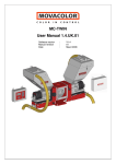
USER GUIDE
UGB014-0209
Software Version V4.0
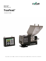
TrueFeed ™
Gravimetric Feeder
Co rpo r a te O f fic e : 41 2.3 12. 600 0 | I n s t ant Acc es s 2 4/7 ( Pa r ts an d Se rv ice ): 800 . 458. 196 0 | P a rts and Se rvic es : 814 .43 7.6 861
INDEX
1. Introduction ______________________________________________________________________________________________ 1
1.1 Symbols ________________________________________________________________________________________________ 1
1.2 Terms ________________________________________________________________________________________________ 1
2. General information _______________________________________________________________________________________ 2
2.1 Safety ________________________________________________________________________________________________ 2
2.2 Certification____________________________________________________________________________________________ 2
2.3 Operating environmental conditions _________________________________________________________________________ 2
3. Overview Feeder __________________________________________________________________________________________ 3
3.1 TrueFeed cmponent overview _____________________________________________________________________________ 3
3.2 Weighing frame_________________________________________________________________________________________ 4
3.3 Motor and feeding system ________________________________________________________________________________ 4
4. Metering principle _________________________________________________________________________________________ 5
5. Feeding systems / Capacities _______________________________________________________________________________ 6
6. Installation _______________________________________________________________________________________________ 8
6.1 Transport _____________________________________________________________________________________________ 8
6.2 Receipt _______________________________________________________________________________________________ 8
6.3 Mechanical istallation ____________________________________________________________________________________ 8
6.4 Changing from dispensing cylinders to Feed screw _____________________________________________________________ 9
6.5 Electrical installation ____________________________________________________________________________________ 10
7. Operation _______________________________________________________________________________________________ 12
7.1 Navigation____________________________________________________________________________________________ 12
7.2 Start up and login ______________________________________________________________________________________ 13
7.3 Keyboard lock _________________________________________________________________________________________ 14
7.4 CONFIGURATIONS ____________________________________________________________________________________ 15
7.5 Load cell calibration ____________________________________________________________________________________ 21
7.6 Material pre-calibration __________________________________________________________________________________ 23
7.7 Production____________________________________________________________________________________________ 25
7.8 Auto / Manual regulation mode and save data function _________________________________________________________ 28
7.9 Production JOB________________________________________________________________________________________ 29
7.10 Filling the hopper _____________________________________________________________________________________ 30
7.11 Consumption_________________________________________________________________________________________ 34
7.12 Alarms______________________________________________________________________________________________ 35
7.13 Files _______________________________________________________________________________________________ 37
7.14 Event LOG __________________________________________________________________________________________ 38
8. System performance______________________________________________________________________________________ 39
8.1 Reset regulation _______________________________________________________________________________________ 39
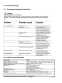
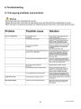
9. Troubleshooting _________________________________________________________________________________________ 40
APPENDIX A:
TrueFeed Print view_________________________________________________________________________ 41
APPENDIX B:
TrueFeed Wiring Diagram ____________________________________________________________________ 42
APPENDIX C:
TrueFeed Technical Specifications ____________________________________________________________ 43
APPENDIX D:
TrueFeed Quality Checklist __________________________________________________________________ 44
APPENDIX E:
ME Hopper Loader __________________________________________________________________________ 46
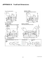
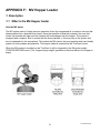
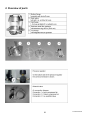
APPENDIX F:
MV Hopper Loader __________________________________________________________________________ 52
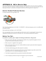
APPENDIX G:
We’re here to help __________________________________________________________________________ 62
APPENDIX H:
TrueFeed quality checklist ___________________________________________________________________ 64
1. Introduction
Thank you for purchasing the Conair TrueFeed. This manual is addressed to operators and qualified
technicians taking care of the feeding of dry additives to ensure correct use of the TrueFeed.
IMPORTANT: THIS MANUAL MUST BE READ BEFORE INSTALLING THE FEEDER. KEEP THIS
MANUAL IN A PLACE ACCESSIBLE FOR ALL OPERATORS.
Conair recommends that you record the model and serial number(s) of your equipment and the date you
received it in the User Guide. Our service department uses this information, along with the manual number, to
provide help for the specific equipment you have installed.
Please keep this user guide and all manuals, engineering prints and parts lists together for documentation of
your equipment.
Date:
Manual Number: UGB014-0209
Serial Number(s):
Model Number(s):
Software Version:
Disclaimer: The Conair Group, Inc. shall not be liable for errors contained in this User Guide or for incidental, consequential damages
in connection with the furnishing, performance or use of this information, including, but not limited to the implied warranties of
merchantability and fitness for a particular purpose.
1.1 Symbols
Important note
Attention; safety regulations for the operator
1.2 Terms
Operator:
A person charged to operate, adjust, maintain and clean the machine.
Qualified Technician:
A specialized, suitable trained person authorized to execute the installation, nonroutine maintenance or repairs requiring special knowledge of the machine and
how it operates.
© Copyright 2009, The Conair Group, Inc., All rights reserved
2. General information
2.1 Safety
This equipment is only designed and may only be used for the feeding of dry additives.
Any use that is not in conformity with the instructions is considered improper and as such frees the
manufacturer from any liability regarding damage to equipment and/or persons.
Before turning on the unit for the first time, ensure that the main power voltage
applied is between 80 and 260 VAC.
Always turn off the TrueFeed and disconnect the main power plug from electrical power before
performing maintenance.
Ensure that all parts are securely fixed to the extruder or injection molding machine.
Dangerous voltages are present inside the TrueFeed control for up to two (2) minutes after the
TrueFeed has been turned off.
2.2 Certification
The Conair TrueFeed is designed and produced in conformity with the following European regulations:
•
Standards for machinery (health, safety and environment)
• EMC (electromagnetic compatibility)
• VEM (safety electric material)
• 98/37/EC, Annex 1
2.3 Operating environmental conditions
•
•
•
The unit must be protected against weather conditions
Operating temperature -4° to 158° F {-20° to 70° C}.
Protection class: IP-50
2
TrueFeed manual
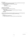
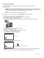
3. Overview feeder
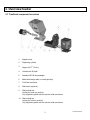
3.1 TrueFeed component overview
1
Stepper motor
2
Dispensing cylinder
3
Hopper 0.2 ft
4
Curled knob M10x40
5
Standard NST40 throat adaptor
6
Material discharge slide (in closed position)
7
TrueFeed load frame
8
Slide frame (optional)
9
Slide locking bolt
(locking the slide-out position)
Only supplied together with the optional slide mechanism
10
Slide locking bar
(locking the slide-in position)
Only supplied together with the optional slide mechanism
3
{6 liter}
3
TrueFeed manual
3.2 Weighing frame
Safety bolts
(total of 4)
Transport protection pin
Hopper loader tube support
Balance frame (when option
selected)
The black part is the weighing frame.
Do not touch the weighing frame (and dispensing unit) while feeding, it will influence operation.
Do not touch the safety bolts under the weighing platform. These are for overload protection.
There must be space between the safety bolts and the frame.
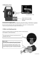
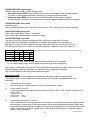
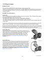
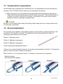
3.3 Motor and feeding system
There two (2) feeding systems, the dispensing cylinder and the feed screw.
(See Chapter 5 for more information)
The serial number of the motor can be found on the
backside of the motor.
Motor shaft:
The motor shaft is equipped with one flat side which
fits precisely in the shaft of the dispensing cylinder.
To connect the dispensing cylinder, place it on the
motor shaft while turning it to find the flat side, then
push the dispensing cylinder completely backwards.
4
TrueFeed manual
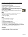
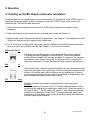
4. Metering principle
The Dispensing cylinder® of the TrueFeed is combined with a very precise adjustable stepper motor ensuring
that the additive output is accurate and consistent. The throat adapter (a mixing chamber) is designed to blend
the main material and the additive homogeneously. Conair supplies a large range of machine throat adaptors
that make a perfect fit to your injection molding machine or extruder. The most common mounting of the throat
adaptor is between the production machine and the machine hopper. In the figure below, a cross section of the
NST40 throat adaptor can be seen.
Standard throat adaptor
During operation, the virgin material runs from the
machine hopper through the throat adaptor into the
machine. Inside the throat adaptor the virgin material
flow is divided into two streams by the cover plate. In
the space below the cover plate, the rotating cylinder
is feeding additive.
2
1
5
4
Additive is added directly into the center of the virgin
material flow, just before it enters the production
machine. This is a great advantage over metering
devices that use batch pre-mixing; because premixing can actually cause material separation.
Separation of material results in an irregular additive
flow into the production machine.
3
6
7
Fig. 3
1. Color 2. Virgin material 3. Throat adaptor 4. Dispensing cylinder
5. Cover plate 6. Mixing zone 7. To production machine
5
TrueFeed manual
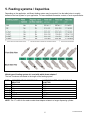
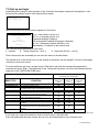
5. Feeding systems / Capacities
Depending on the application, a different feeding system may be required. Use the table below to roughly
determine the best system for your application. For more detailed information contact a Conair representative.
Which type of feeding system do I need with which throat adaptor?
The last 3 numbers are related to the length of the feeding system.
TYPE
GLX
GX
HX
A15LT
A20LT
A20HT
A30HT
CODE FOR STANDARD THROAT
ADAPTOR
GLX
GX
HX
A15
A20
A20HT
A30
CODE FOR WATER-COOLED THROAT
ADAPTOR
GLXC
GXC
HXC
A15C
A20C
A20HTC
A30C
NOTE: The “C” suffix for the water-cooled throat adapter relates to a longer dispensing cylinder.
6
TrueFeed manual
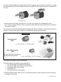
All Conair TrueFeed feeders are equipped with the 2A (LT) stepper motor as standard. In case you are using
an A30 feed auger, the 4.5A (HT) stepper motor will be supplied. The A20 auger can also be connected to the
HT motor.
4.5A (HT) Stepper motor
2A (LT) Stepper motor
Do not select the HT setting in the control if a LT motor is connected. This will damage the motor.
If a LT motor is selected and a HT motor is connected, there will be less motor torque which can influence
the feeding of additive.
The control of the TrueFeed makes a distinction between two groups of materials, normal granules and microgranules. To determine the type of material in your application use the description below.
Material types
Normal Granules:
(NG) 3
Ø
L
Ø<
0.2 in. {4 mm} L < 0.2 in. {4 mm} *
Micro / Mini Granules:
(MG)
ø
L
The term Micro/Mini Granules also
includes free flowing powder.
Ø<
0.1 in. {2.5 mm}
L < 0.1 in. {3 mm} *
* For other sizes contact a Conair representative.
The actual capacity of the feeding system depends on:
• The volume weight of the material (bulk density)
• The specific weight of the material (specific density)
• The granular shape of the material
• The granule size
• The surface structure of the material
Granular material can be normal or micro. The granular material or powder material must be free flowing,
non-static and not sticky.
7
TrueFeed manual
6. Installation
6.1 Transport
To protect the TrueFeed against damage during transport, the unit is packed in a cardboard box filled with
foam. Delivery terms are FOB Franklin, PA. The buyer is responsible for the transport. Conair cannot be held
liable for any damage that may occur during transportation.
6.2 Receipt
Inspect the unit thoroughly upon receipt. Pass any remarks to the local agent or Conair within eight days from
receipt of goods.
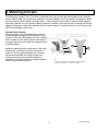
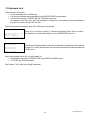
6.3 Mechanical installation
Most mechanical parts are pre-assembled, making installation quick and simple.
1. When installing the main material hopper (not included
with feeder purchase) on top of the throat adaptor, the
top flange of the NST40 throat adaptor needs to be
drilled to match. The lid of the throat adaptor can be
removed for easy machining.
Removable top
flange for easy
machining.
Take out the window
in a 45° angle for
easy cleaning.
2. -Install the throat adaptor directly on top of the inlet
of the production machine.
-Install the throat adaptor at a 90-degree angle to the
machine barrel. This will optimize the feeding accuracy
in relation to vibrations of the production machine.
-Ensure that the entire unit is mounted
horizontally level and fixed securely.
-Assure proper grounding to control cabinet,
throat adaptor and feeder.
Curled knob
3. Remove the transport
protection pin (at the bottom
of the load cell frame) before
mounting the hopper
Transport
assembly.
protection pin
This is just a pin on a flexible
chain; do not remove the stainless steel plate!
Main material
hopper
Hopper
assembly
4. Connect the hopper assembly to the throat adaptor
by turning the curled knob clockwise. Ensure that the
curled knob is tightened firmly.
5. Mount the control in a vibration free area and away from
high temperatures.
8
Horizontally leveled
(Water leveled)
Barrel
90°
Install the throat adapter at a 90-degree angle to the
machine barrel. As shown in the picture above.
TrueFeed manual
6.4 Changing from dispensing cylinder to feed screw
In relation to the maximum capacity of the dispensing cylinder, it may be necessary to change from the
selected dispensing cylinder to a feed auger. The feed auger system consists of a rotating auger in a nonrotating tube.
3
5
1
2
4
To install the feed auger:
1. Detach the motor quick release clamps and remove the motor from the hopper.
2. Dismount the throat adaptor connection flange (1) by removing the four socket-head screws.
3. When using a dispensing cylinder, the throat adaptor connection flange (1) is equipped with a ball bearing
(5). When using an auger screw system the ball bearing must be removed. The metal ring (2) which is fixed
on the feed screw tube fits directly on the throat adaptor connection flange.
4. Remove the dispensing cylinder (3) and mount the screw (4) with the M5 bolt.
5. Replace the motor and auger by closing the motor quick release clamps.
The motor and auger can be easily removed for cleaning.
POSSIBLE COMBINATIONS
A15/ 20 / 30
GX / GLX / HX
Art.nr:H000002
Art.nr:H000011
Included ball bearing
9
TrueFeed manual
BALL BEARING
To clean the ball bearing, use a dry piece of textile or a smooth, dry toothbrush to remove the dust or
moisture and foreign particles that may accumulate.
The following points have effect on the lifetime of the ball bearing:
o Abrasive materials
o Temperature
o Dusty / fine powder materials
6.5 Electrical installation
The TrueFeed control is equipped with three (3) connections:
• Main power cable
Before turning on the unit for the first time, ensure the main power voltage being
applied is between 80 and 260VAC.
• Input cable
• Motor cable
Be aware that the cables will be influenced by external circumstances such as electromagnetic fields!
Mount the control on a location that is free of vibrations and excessive heat.
Optional are:
• Alarm flash light, complete with cable
• Compressed air solenoid valve complete with cable (for automatic hopper loading)
10
TrueFeed manual
APPENDIX B SHOWS THE ELECTRICAL PRINT VIEW WHICH IS EXPLAINED BELOW
1. PROCESSOR BOARD
The processor board is the heart of the control.
The board must be fixed securely on the mainboard.
There is a Mac-address that is labeled on the process board. This is the ID of the networkcard.
This address can also be seen in the startup screen on the TrueFeed control display.
2. EXTERNAL TERMINAL CONNECTION
This connection is used when using an external terminal (Shielded cable max. 32.8 ft {10 m})
3. CONNECTION TO PC OR NETWORK
The Ethernet connection will be used when the TrueFeed is connected to a PC or
network. Maximum length of the UTP network cable, type RJ45 (Cat. 5) is 328 ft {100 m}
between two network points.
4. INPUTS
Start input
The TrueFeed needs an input signal from the production machine in order to operate.
Three (3) different input signals can be used to control the TrueFeed:
• Potential free start input (dry contact)
• Potential (24 VDC) start input
• Tachometer (0-30 VDC) start input
5. MOTOR
The TrueFeed can control two (2) motor types:
• LT (low torque) standard motor for normal feeding
• HT (high torque) motor for high output feeding
(See Chapter 5 for more details. See Appendix B for wiring diagram and electrical connection information.)
6. OUTPUTS
The TrueFeed has the following outputs available:
• [clamp 24-25] Valve output for hopper loader, (Solid state 24VDC/0.5 A)
• [clamp 22-23] Warning output (Solid state 24VDC/0.5 A)
• [clamp 26-27] Potential free relay (normally-open) output for alarm (max. 230VAC/30VDC, 5A)
• [clamp 28-29] Potential free relay (normally-open) output for running contact
(max. 230VAC/30VDC, 5A). This contact will be used to show that the TrueFeed motor is running.
The maximum total output power is 12 Watt (Valve output + alarm output together max. 0.5A)
(See Appendix B for wiring diagram and electrical connection information.)
7. POWER SUPPLY
The TrueFeed will operate with a voltage between 80 VAC to 260 VAC, 50 and 60 Hz
by an integrated automatic voltage selector.
(See Appendix B for wiring diagram and electrical connection information.)
11
TrueFeed manual
7. Operation
7.1 Navigation
Alphanumerical
buttons:
Set values /
descriptions
Input LED is lit: Input
signal is ON
Enter:
Confirm settings /
Pick up a JOB
Alarm LED is lit:
Alarm / warning
Stop:
Stop unit
Arrow left / right:
Scroll through menus /
settings
Start:
Start unit
Enter / scroll / exit MENU
Arrow up / down:
Scroll through parameters
Start LED blinking:
Motor is standing by / waiting for start signal
Start LED lit:
Motor is running
Mains power switch: ON / OFF
Load cell
External communication /
Network
Main power cable
Start input cable
Motor cable
Valve output
for hopper loader
12
Output for:
-Alarm
-Warning
-Running
TrueFeed manual
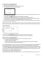
7.2 Start up and login
Immediately after turning on the main power to the TrueFeed, the software versions will be displayed. In the
first screen the software version of the terminal will be shown.
Conair Terminal
Version x.xx
Date: January 2005
After a few seconds the second screen appears for 10 seconds.
Conair TrueFeed
Color in Control
Vx.x
SP-Vx.x
MENU to continue
BL Vx.x
Mac-00:12:EC:xx:xx:xx
Vx.x = User software version Vx.x
SP-Vx.x = Language version Vx.x
(Standard language is English)
(SP means that the additional language is Spanish)
BL Vx.x = Bootloader software (firmware) Vx.x
Mac address = ID address of the network card
The TrueFeed control has three (3) user levels:
1. Operator
2. Tooling (Supervisor – level 1)
3. Supervisor (Service – level 2)
The functions which are accessible per user level are shown in the table below.
The Operator level is the lowest level, only the settings for production can be changed. The rest of the settings
/ menus are removed or locked.
To access a different user level, navigate to the LOGIN menu and enter the corresponding password (4
numerals) and press “Enter”. The passwords for the Tooling and Supervisor user levels can be defined by the
supervisor in the CONFIGURATIONS menu.
USER LEVEL
Can be changed in LOGIN menu.
MENU TITLE:
[LOGIN]
[CONFIGURATIONS]
[PRODUCTION]
[FILES]
[HOPPER LOADER]
[CALIBRATION]
[LOAD CELL]
[WEIGHT CHECK]
[CONSUMPTION]
[ALARMS]
[EVENT LOG]
FUNCTION:
To enter the different user levels.
To configure the feeding system.
To adjust the production settings.
*In OPERATOR level jobs and materials are read-only.
To look for, rename or delete jobs and curves.
To adjust the hopper loader settings,
only visible when a hopper loader is selected.
To make material calibrations, only visible when control
mode is set to GRAVI (Gravimetric).
To calibrate the load cell.
To check the hopper or object weight.
Viewing of the total quantity of material dosed by the
TrueFeed.
Viewing of the alarm history
*In TOOLING level the alarm CONFIGURATIONS is
removed.
The history of events or settings will be logged in this
menu.
SUPERVISOR
Default code
2222
TOOLING
Default code
1111
OPERATOR
Default code
0000
YES
YES
YES
YES
NO
NO
YES
YES
YES*
YES
NO
NO
YES
YES
YES
YES
YES
NO
YES
NO
NO
YES
YES
NO
YES
YES
NO
YES
YES*
NO
YES
NO
NO
Recommended to note the passwords
If you forgot your supervisor password, contact Conair Service 1-800-458-1960.
If the wrong password has been entered, the user level will automatically be set to Operator level.
13
TrueFeed manual
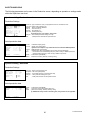
7.3 Keyboard lock
The keyboard lock function:
• Is only accessible at the LOGIN menu.
• Can only be activated and deactivated with the SUPERVISOR login password.
• Is only fully functional in OPERATOR and TOOLING user levels.
For example: if the “Start user” setting is configured to “Supervisor”, the keyboard lock is deactivated as
soon as the control is turned OFF and ON.
The following screen will appear when the LOGIN menu is accessed:
USER
LEVEL
Enter the password to set
the user level.
Level
: SUPERVISOR
Key lock: Unlocked/Locked
MESSAGE
Keyboard locked !
To unlock enter
supervisor code.
Press Æ or Å to select “Locked” or “Unlocked” and press “Enter”. When “Locked”
is selected the unit will automatically be set to OPERATOR user level.
This screen will appear when a user tries to change any setting while the keyboard
is locked. To unlock the keyboard, the Supervisor password must be entered at the
LOGIN menu.
MENU to continue
When the keyboard lock is ON, it is still possible to…
• Shift between the LOGIN, PRODUCTION and HOPPER LOADER menus.
• To START and STOP the feeder.
See Chapter 7.2 for start-up and login information.
14
TrueFeed manual
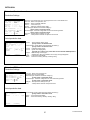
7.4 CONFIGURATIONS
For the initial setup of the TrueFeed, the control must be configured from the CONFIGURATIONS menu.
Depending on the CONFIGURATIONS, some settings will be removed because they are not relevant.
Highlighted Parameters are factory settings.
Language
Motor type
Cylinder type
Material type
Cal dev.
Control mode
Prod. Mode
Input mode
└ Input filter
Fill. System
└ EX HH level
└ EX H level
└ Filling start
Hopper empty
Deviation alarm
Jobs enabled
Auto start
Master reset
IP
Name
Start user
Tooling passw.
Supervisor passw.
Conversion
Full scale
Modbus unit
Date
Time
: ENG / SP
: LT / HT
: GX / GLX / HX / A20 / A30 (for A15 select GX cylinder type)
: NORMAL / MICRO
: 5.0 %
: GRAVI / RPM
: INJ / EXT
: Timer / Relay / Tachometer
: (1 -32)
: NO / ME / MV / EX
: 3500 g. (7.7 lb)
: 2500 g. (5.5 lb)
: 800 g. (1.7 lb)
: 700 g. (1.5 lb)
: 25 %
: NO / YES
: NO / YES
: NONE / ALARM / MATER / JOBS / ALL
: xxx . xxx . xxx . xxx (For example: 192.168.001.001)
: xxxxxxxxxxxxxx
: Operator / Tooling / Supervisor
: xxxx 1111
: xxxx 2222
: Metric / Imp / kg/h
: xx.xx kg
: 1 - 231
: (dd / mm / yy)
: (hh / mm / ss)
CONFIGURATIONS: Language
Standard language is English. Alternate languages are available upon request.
CONFIGURATIONS: Motor type
LT is Low Torque motor and HT is High Torque motor (See Chapter 5 for more information)
Do not select HT motor if a LT motor is installed.
CONFIGURATIONS: Cylinder type
Type of dispensing cylinder / feed auger (See Chapter 5 for more information)
CONFIGURATIONS: Material type
Type of material: normal granules (NORMAL) and micro-granules (MICRO).
(see chapter 5 for more information)
CONFIGURATIONS: Cal dev.
The maximum allowed deviation from the Calibration Setpoint can be set with this
parameter. (See Chapter 7.6 for more information)
15
TrueFeed manual
CONFIGURATIONS: Control mode
(GRAVI) Gravimetric mode or (RPM) Rotating mode
• Gravimetric mode (GRAVI) is set as default and functions on the basis of loss-in-weight principle.
The output is measured and regulated continuously by controlling the motor speed.
• Volumetric mode (RPM) can be used if no automatic feedback of the weight is required.
The weighing will not function in this mode and the automatic hopper loader function will not operate.
CONFIGURATIONS: Prod. mode
Production mode
Type of processing machine the TrueFeed is mounted upon. (EXT) extruder or (INJ) injection molding
CONFIGURATIONS: Input mode
Type of input signal. Relay, Timer or Tachometer
Timer mode is the standard setting for Injection molding.
CONFIGURATIONS: Input filter
The setting “input filter” becomes visible when Relay Input mode is selected in INJ mode.
In Relay Input mode the length of feeding time is measured automatically from the incoming
input signal. The Input Filter calculates the average feeding time of the set number of shots (3-32)
The calculated average time is used as consistent feeding time. The default Input Filter setting is 3.
EXT
timer
relay
tachometer
INJ
x
x
Input mode is not visible in RPM Production mode. (Timer mode is used automatically)
x
x
x
x
x
GRAVI RPM GRAVI RPM
For INJ mode in Timer mode, the start pulse should be a minimum of 0.2 seconds.
For INJ mode in Relay mode, the start signal should be as long as the feeding time.
If INJ mode in Relay mode is selected, the TrueFeed will follow the machine relay time. The control will filter
out small changes so that the regulation is not affected. Large changes will be followed.
The TrueFeed display will show the actual machine relay time.
Input (start) signal
The TrueFeed needs an input signal from the production machine in order to function properly.
Three different types of input signals can be used to control the TrueFeed. See Appendix B for more
information.
1.)
A potential free relay contact.
Use the white wire (14) and brown wire (15) for the potential free contact.
2.)
A relay signal 24 Volt DC*.
In case of a powered relay signal connect the white wire (14) to the +24 VDC and the yellow wire (12)
to the 0 VDC.
* Note potential contact
Guaranteed OFF: 0-8VDC
Guaranteed ON:
18-30VDC
3.)
A tachometer signal up to 30 Volt DC.
This is used when the TrueFeed needs to be connected to an extruder that has a tachometer generator
that produces a voltage linear to the extruder speed. When using a tachometer generator signal, make
a connection between the white wire terminal (14) and brown wire terminal (15), it will function as a start
signal. Connect the positive VDC (green) wire from the tachometer to terminal (13) and the negative
(yellow) wire to terminal (12).
TrueFeed manual
16
The maximum voltage that can be applied to the TrueFeed is 30 VDC. The tachometer voltage must be
reduced to 30 VDC. If the tachometer generator has a higher voltage output than 30 VDC at the maximum
extruder output capacity, it must be reduced. See the diagram below.
Input
connection
Green wire +
13
12
Resistor (Rx)
Yellow wire -
Tachometer
generator
EXTRUDER
Rx (kilo-Ohm) = (2,684 x (Max. tacho output VDC – 5)) -66
If the extruder stops when it is connected to the TrueFeed, an isolated signal converter is required. Contact a
Conair representative for more information.
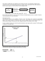
Tachometer function
The tachometer function is only available in Extrusion mode. The feeding rate is required to automatically
adjust to the extruder’s speed. In Tachometer mode, an input voltage is linked to a feed speed setting. If the
extruder speed changes, the tachometer input voltage and speed of the feeding will also change.
A linear correlation between the extruder’s speed (tachometer input signal) and the required TrueFeed speed
is displayed in the graph below.
Speed (RPM)
Tachometer graph
(Example)
Tachometer input voltage (VDC)
The tachometer function can be set in the PRODUCTION screen.
The tachometer setting can be adjusted automatically or manually.
Max tachometer:
Set tachometer:
0.0V
NO / YES
Highlighted Parameters are factory settings.
17
TrueFeed manual
Manual:
Fill in the voltage the tachometer produced by the tachometer generator at maximum extruder speed.
Automatic:
Let the extruder run and select Set tachometer: YES.
The tachometer voltage (P1) will be taken over automatically and is linked to the set motor speed (P2) (in RPM
mode) or calculated motor speed (in GRAVI mode)
During production, the motor speed (P2) can be changed. The new speed is linked to the previous stored
voltage and the graph will change accordingly.
During production, the voltage (P1) can be adjusted to the current tachometer input voltage (manually or
automatically) as shown above. The new voltage is linked to the previous stored speed and the graph will
change accordingly.
-The maximum voltage that can be applied to the TrueFeed is 30 VDC.
-The tachometer signal must be a clear signal. Any failure in the voltage signal will result in feeding variations.
CONFIGURATIONS: Fill. System
Filling system, NO (None), ME, MV or EX (See Chapter 7.10)
CONFIGURATIONS: Filling start
Function: When the control detects that the hopper is running empty, the filling system is activated.
The filling system will start loading when the weight in the hopper is 1.7 lb {800 g} (default) or less.
The default value can be changed manually if necessary (depending on the material properties).
Also with an EX hopper selected, this is the weight level for opening the knife gate valve to fill
the hopper.
Only visible when a filling system is installed and selected.
CONFIGURATIONS: EX-H level
The filling knife gate valve will close if the weight in the hopper is 5.5 lb {2500 g} (default) or more.
Only visible if EX (External / foreign) hopper loader is installed and selected.
CONFIGURATIONS: EX-HH level
HH level is High level warning. If the weight in the hopper reaches 6.6 lb {3000 g} (default) or more a warning
will activate.
Only visible if EX (External / foreign) hopper loader is installed and selected.
CONFIGURATIONS: Hopper empty
The system will display a “Low hopper level” message if there is less then 1.5 lb {700 g} (default) of material in
the hopper. For this system to work correctly it is required that a load cell calibration is performed with an
empty hopper and the hopper lid in place. This system will always be active.
The default value can be changed manually if necessary (depending on the material properties).
See Chapter 7.12 for instructions on how to set this message to alarm or warning.
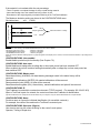
CONFIGURATIONS: Deviation alarm
Setting for the “Maximum deviation exceeded” message.
The TrueFeed automatically adjusts its motor speed to the desired setpoint. The control is able to detect and
alarm when the setpoint is not reached within a set percentage. If after the normal performed speed
adjustments, the setpoint is consistently not reached, the control will activate an alarm signal and a message
will be displayed in the TrueFeed’s control.
18
TrueFeed manual
If the setpoint it not reached within the set percentage:
- There is a partial or complete blockage of sticky or hard flowing material.
- Inaccurate feeding due to the material not being uniform in size.
- Disturbance of the weight signal by mechanical blocking of the TrueFeed loadframe.
The Maximum deviation setting can be set in the CONFIGURATIONS menu:
Deviation alarm:
xx% (1-99%)
Output [gram/sec]
+ limit :
Setpoint [gram/sec.]
maximum deviation % setting
- limit :
Time
Example:
The Deviation alarm setting in the CONFIGURATIONS menu is set to 25% as default.
The setpoint (color set) is set to
: 2.2 lb/sec {1,000 g/sec}
-the MAXIMUM limit value will be
: 2.7 lb/sec {1,250 g/sec}
-the MINIMUM limit value will be
: 1.6 lb/sec {750 g/sec}
When the maximum deviation message (Error 01, page 34) appears in the display of the control, it shows the measured deviation in percentage of the
setpoint.
CONFIGURATIONS: Jobs enabled
Enable/disable production job functionality (See Chapter 7.9)
CONFIGURATIONS: Auto start
Enable/disable auto startup after a voltage dip or when main power has been switched OFF.
When enabled, the unit will continue feeding automatically after a voltage dip or when main power has
been switched OFF.
CONFIGURATIONS: Master reset
Reset alarm history (ALARMS). All alarm/warning messages saved in the alarm history will be
removed.
Reset material calibrations (MATER.) All material calibrations will be removed.
Reset production jobs (JOBS). All Jobs will be removed.
Reset these three together (ALL). Alarm history, material calibrations and jobs will be removed.
CONFIGURATIONS: IP
The IP-address is used within a network environment (TCP/IP protocol). (For example 192.168.001.001)
When a TrueFeed is part of a network, the control must have an IP-address for identification.
This IP-address has to correspond with the IP-address of your computer. Ask your network administrator for a unique address.
CONFIGURATIONS: Name
Provide a name or figures for individual identification (for use within a network).
For example, the name of the machine the TrueFeed is mounted upon.
CONFIGURATIONS: Start user (Sign-in)
User level to start up with, when switching on the control’s main power.
Operator, Tooling or Supervisor.
19
TrueFeed manual
CONFIGURATIONS: Tooling password
Password for Tooling user level, 4 numerals, default: 1111
CONFIGURATIONS: Supervisor password
Password for Supervisor user level 4 numerals, default: 2222
CONFIGURATIONS: Conversion
Selection of Units:
Metric = European [gr/s]
Imperial = US [lbs/hr]
Kg/h = In extrusion mode the capacity will be shown in kg/h instead of gr/s
CONFIGURATIONS: Full scale
Selected load cell will be shown (read-only)
CONFIGURATIONS: Modbus unit
If the control is used within a Modbus network, the unique identity can be entered here (1-231)
CONFIGURATIONS: Date
Actual date (dd / mm / yy)
CONFIGURATIONS: Time
Actual time (hh / mm / ss)
Date and time will be stored for a minimum of 1500 hours when the control is switched OFF.
20
TrueFeed manual
7.5 Load cell calibration
Two types of calibrations are available for the TrueFeed, depending on the selection made in
CONFIGURATIONS:
1. Automatic - The advantage of automatic calibration over manual calibration is that the automatic
calibration is self-calibrating and the probability of failures will be reduced. Also, the accuracy is higher
with changes of output because a complete material curve will be produced.
2. Manual - Running in RPM mode (external scale is required)
When using a TrueFeed for the first time, a load cell calibration must be performed:
•
•
•
•
The unit must be mounted horizontally (water leveled)
Avoid vibrations during the load cell calibration. This will effect the calibration.
Do not touch the unit during load cell calibration.
When using an optional slide frame the unit must be slid in against the throat adaptor and secured.
•
•
•
Be sure that the load cell is connected to the control
Navigate to the LOAD CELL menu
In this menu it is possible to calibrate the load cell of TrueFeed
(a 1.1 lb {500 g}. calibration weight is required)
Select “YES” to start the load cell calibration
•
LOADCELL CALIBRATION
[***]
[***] = Progress
Status
Calibration busy.
Please wait…………..
•
After a few minutes the following screen appears:
LOADCELL CALIBRATION
[***]
Status
Place weight, press
START when ready.
•
•
Place the calibration weight (1.1 lb {500 g}) on the hopper
and press the “START” button.
After approximately one (1) minute the load cell calibration will be complete, press the “MENU” button to
continue.
To check if the load cell calibration was correct, navigate to the WEIGHT CHECK menu.
21
TrueFeed manual
WEIGHT CHECK
Weight:
Object:
Zero:
•
•
•
gr.
gr.
NO/YES
><
><:
Weight:
Object:
Zero:
Standstill sign. When the vibrations are too large, this sign disappears!
Actual weight on the weighing scale (gram)
Object weight (gram)
Zero YES / NO. Reset the object weight.
Zero the object weight
Place the 1.1 lb {500 g} calibration weight on the hopper
If the object weight is not corresponding with the weight readout in the control’s display, perform another
load cell calibration.
22
TrueFeed manual
7.6 Material pre-calibration
The TrueFeed can be started in two ways:
1) Without pre-calibration of material.
After pressing the “START” button the TrueFeed starts feeding at a speed that is based on default curves
which are pre-programmed within the control. After start-up, the unit continues with self-calibrating to
setpoint.
2) With pre-calibration of material (OFF-LINE).
After pressing the “START” button the TrueFeed starts feeding at a speed that is based on material
calibrations made by the user that are stored within the control. After start-up, the unit continues with finetuning to setpoint.
What is the function of a material Pre-calibration?
With a pre-calibration it is possible to calibrate the unit before production begins, reducing the time for the
TrueFeed to be within tolerance. The TrueFeed is a gravimetric/loss-in-weight feeder. When starting up the
feeder for a new production run, there is no direct information available about the loss in weight. Starting the
unit at a speed that is already near to the setpoint will achieve quicker regulation. The correct RPM at the start
of the feeder can be determined automatically with a pre-calibration.
The pre-calibration can performed in two (2) ways:
1) Unit with the optional slide frame:
Slide the frame with unit backwards till the “click”
•
•
•
2) Unit without optional slide mechanism:
Remove the feeder and place it on the frame as shown
It is important that during calibration, the feeder is mounted fixed, horizontally and vibration free.
Before starting a pre-material calibration, ensure that the hopper is filled with material.
Ensure that the load cell cable is connected to the TrueFeed control.
Following parameters will be stored with the Material calibration, depending on the CONFIGURATIONS:
•
CONFIGURATIONS parameters:
•
PRODUCTION parameters:
•
CALIBRATION parameters:
Cylinder type : Type of dispensing cylinder or feed screw
Material Type : Normal or micro-granules
Shotwth.
: Shot weight
color%
: Color amount (%)
dos. time
: *Feeding time (sec)
Ext. cap.
: Extruder capacity (kg/h)
Material name : Name of calibrated material
* Screw recovery time for an injection molding machine.
23
TrueFeed manual
How do I make a material calibration?
• Navigate to the CALIBRATION menu.
• Enter the material name and your production parameters.
• Start calibrating. The following screen appears:
CALIBRATION
[TESTING BUSY]
[*****]
Set
: 1,000 gr/s
Actual : 0,945 gr/s
Stop & Store : YES/NO
•
•
•
The calibration will take approximately three (3) minutes but can take longer depending on the material
used and production parameters.
It is possible to stop the calibration to refill the hopper, for example.
To continue, select “YES” and press “Enter”. To stop, select “NO” and press “Enter”.
The calibration will automatically finish and save after the setpoint is within the set calibration deviation
(Cal dev: default = 5%) set in the CONFIGURATIONS menu. (See Chapter 7.4)
The control will automatically go to the PRODUCTION menu and the stored calibration will be selected.
Stored material curves have a * after the filename.
During the calibration the TrueFeed is adjusting to its setpoint. When the setpoint is reached, the calibration
will be saved. A complete material calibration curve is made on the basis of default pre-programmed curves.
Material Calibration
Single point calibration on basis of
pre-programmed curve
You can also save the actual material calibration during a running production process.
This function is called “Save data Function”. (See Chapter 7.8 for more information)
How can I select a calibrated material?
When one or more material calibrations are made, one can be selected as follows:
• Navigate to the PRODUCTION menu.
• Use the cursor to go to Material.
• Press the “Enter” button for two (2) seconds. A list will appear with stored material calibrations
• Select one with the arrow buttons and press “Enter”.
If the material calibration made is not in the list, enter the first letters of the calibration name and press “Enter”.
Now a filtered list appears. To go back to the main list, fill in the selection with spaces and press “Enter”.
It is also possible to fill in the material description immediately in the PRODUCTION menu and press “Enter”.
The message “Material not found, select new material” appears when a false material is filled in. To clear
the description, fill in the selection with spaces or select an empty calibration out of the list and press “Enter”.
How can I delete or rename a calibrated material?
To delete one or more material see Chapter 7.13.
To delete all Materials, select master reset MATERIAL in the CONFIGURATIONS menu and press “Enter”.
24
TrueFeed manual
7.7 Production
The rotation direction of the feeding at the front view must be to the right
(Clockwise)
Production (Motor On/Off)
Press the “Start” button to start feeding, a question will be displayed: Fill cylinder? YES/NO.
“YES” means that the dispensing cylinder will be filled before production.
The start LED blinks when the unit is waiting for an input signal.
The unit is feeding if the Start LED is continuously lit.
When the unit is started the actual production data will be shown.
Press the “Stop” button to stop production.
Please notice that it is possible that the first feeding(s) are not sufficient, because of the dispensing cylinder is filling with material.
Four levels of production screens:
The TrueFeed will automatically switch to the STATUS screen.
In INJ mode the remaining number of shots will be shown
In EXT mode the remaining production minutes will be shown
Calculated with the actual hopper weight and hopper empty weight
PRODUCTION SETTINGS
Ref Curve: MOVA
Prod Job : xxxxxxxx
Material : xxxxxxxx
Color % : x.xxx %
Shot wth.: xxxx.x gr
Dos.time : xx.x
s
Save Job : YES/NO
Test
: YES/NO
STATUS
Set :
1,800 %
CALIBRATING/CALIBRATED
START
MIN or SHOTS
MENU
MENU
PRODUCTION
Regulation mode :
Auto/Manual
PRODUCTION
Col.set. : x.xxx
Col.act. : x.xxx
Hopper
: xxxx
Time
:
x.x
Speed
: xxx.x
MENU
DATA
gr/s
gr/s
gr ><
sec
rpm
Save data : NO/YES
Status
: Dosing
This screen is not available in
the OPERATOR use level.
(See Chapter 7.8 for more information)
.
Test function
During a test function, the TrueFeed will dose material with the set feeding time and set/calculated speed.
In Extrusion mode the unit will dose for 30 seconds.
To perform a test:
• Navigate to the PRODUCTION menu
• Fill in the production settings
• Use the arrow buttons to go to Test
• Select “YES” and then press “Enter”
• The unit will run with the set parameters.
It is possible to stop the test by pressing the “Stop” button
25
.
TrueFeed manual
INJECTION MOLDING
The following parameters can be seen in the Production screen, depending on operation or settings made
within the Supervisor user level:
Injection molding / Gravimetric mode
Production Settings
PRODUCTION SETTINGS
Ref.Curve: MOVA/USER
Prod Job : xxxxxxxx
Material : xxxxxxxx
Color % : x.xxx %
Shot wth.: xxxx.x gr
Dos.time : xx.x
s
Save job : NO/YES
Test
: NO/YES
Ref.Curve: Type of reference curve: pre-programmed curve or user-defined curve.
Prod Job : Name of the production Job
Material : Name of material calibration
Color % : Color amount (%)
Shot wth : Shot weight (gr.)
Dos. time : Feeding time (sec.)
Feeding time is only visible in Timer mode
Save job : Save actual production settings into a job
Test:
: Initial production test with set speed and time
Actual production data
PRODUCTION DATA
Col.Set. : x.xxx gr/s
Col.Act. : x.xxx gr/s
Hopper
: xxxx gr ><
Time
: xx.x sec
Speed
: xxx.x rpm
Status
: Feeding
Col.set. : Calculated output (gr/sec)
Col. act. : Actual color output (gr/sec)
Actual color output is only visible after the first automatic RPM adjustment.
Hopper : Material weight in the hopper
><
: Standstill sign. When the vibrations are too large, this sign disappears!
Time
: -Count down of the actual feeding time (sec), when running in TIMER input mode.
-Average feeding time (sec), when running in RELAY input mode.
Speed : Actual motor speed (RPM)
Status : Status of the feeding: Standby / Feeding / Filling
Injection molding / RPM mode
Production Settings
PRODUCTION SETTINGS
Prod Job :
xxxxxxxx
Set speed:
xxx.x rpm
Dos.time :
xx.x s
Save job :
NO/YES
Test
:
NO/YES
Prod Job
Set speed
Dos.time
Save job
Test:
: Name of the production Job
: Set motor speed (RPM)
: Actual feed time (sec), measured from relay
: Save production settings into a job
: Initial production test with set speed and time
Actual production data
Speed
Time
PRODUCTION DATA
:
xxx.x rpm
:
xx.x sec
Status
Speed
Time
Status
: Actual motor speed (RPM)
: Count down of the actual feeding time (sec)
: Status of the feeding: Standby / feeding / filling
RPM mode always needs a set feeding time, relay function is not applicable.
: Feeding
26
TrueFeed manual
EXTRUSION
Extrusion / Gravimetric mode
Production Settings
PRODUCTION SETTINGS
Ref Curve : MOVA/USER
Prod Job : xxxxxxxx
Material : xxxxxxxx
Color %
: x.xxx
%
Ext.cap
: xxxxx.x kg/h
Max tachometer: xxx,x
v
Set tachometer: NO/YES
Save job : NO/YES
Test
: NO/YES
Ref.Curve: Type of reference curve: pre-programmed curve or user-defined curve.
Prod Job : Name of the production Job
Material : Name of material calibration
Color % : Color amount (%)
Ext.cap : Maximum extruder capacity (kg/h)
Max tachometer: Maximum tachometer voltage (v)
Only visible in Tachometer mode
Set tachometer : Automatic voltage take over from tachometer generator
Only visible in Tachometer mode
Save job : Save production settings into a job
Test:
: Initial production test with set speed for 30 seconds.
Actual production data
PRODUCTION DATA
Ext.act.
: xxxxx.x kg/h
Act tachometer : xxx,x
v Col. Set. : x.xxx
gr/s
Col. Act. : x,xxx
gr/s
Hopper
: xxxx gr ><
Speed
:
rpm
Status
: Feeding
Ext. act
: Actual extruder capacity (kg/h)
Only visible in Tachometer mode
Act tachometer : Actual voltage of the tachometer generator (v)
Only visible in Tachometer mode
Col. set : Calculated output (gr/sec)
Col. act. : Actual color output (gr/sec)
Actual color output is only visible after the first automatic RPM adjustment.
Hopper : Material weight in the hopper
><
: Standstill sign. When the vibrations are too large, this sign disappears!
Speed : Actual motor speed (RPM)
Status : Status of the feeding: Standby / Feeding / Filling
Extrusion / RPM mode
Production Settings
PRODUCTION SETTINGS
Prod Job : xxxxxxxx
Set speed xxx.x
rpm
Max tachometer: xxx.x
v
Set tachometer: NO/YES
Save job : NO/YES
Test
: NO/YES
Prod Job :Name of the production Job
Set speed :Set motor speed (RPM)
Max tachometer : Maximum tachometer voltage (v)
Only visible in Tachometer mode
Set tachometer : Automatic voltage take over from tachometer generator
Only visible in Tachometer mode
Save job : Save production settings into a job
Test
: Initial production test with set speed and time
Actual production data
PRODUCTION DATA
Act tachometer : xxx.x
v
Speed
: xxx.x
rpm
Status
Act tachometer: Actual voltage of the tachometer generator (v)
Only visible in Tachometer mode
Speed : Actual motor speed (RPM)
Status : Status of the feeding: Standby / feeding / filling
: Feeding
27
TrueFeed manual
7.8 Auto / Manual regulation mode & save data function
Two functions are available within one screen:
- Regulation mode: Auto/Manual
- Save data function.
These two functions are not accessible within the OPERATOR user level.
Regulation mode: Auto/Manual
This function allows you to switch from automatic control (gravimetric) to manual control (RPM) during
operation. It is only accessible when the TrueFeed’s motor is on and the control is not in the Operator
user level.
PRODUCTION
Regulation mode
Auto/Manual
PRODUCTION
Regulation mode
Manual
Manual Æ ENTER
Man Speed: xxx.x rpm
Save data: NO/YES
Weight
: xxxx gr.
Save data: YES/NO
In this screen the RPM can be changed.
-When changing back to Auto mode without saving data, the unit will revert to the “old” RPM and continue
self-calibrating.
-When changing back to Auto mode after saving data (manual entered speed), the unit will first keep the
manual set speed but will self-calibrate to the entered setpoint.
Save data Function
This selection allows storing the actual data once the feeder shows an actual value (color actual). A material
description needs to be entered to save this data. A full material curve based on the stored point will be saved
in the memory of the control under the entered name.
Starting a new production run with a previously stored material calibration/speed is now possible.
PRODUCTION
Regulation mode
Auto/Manual
PRODUCTION
Fill in material
Description: XXXXXXXX
Save data Æ YES
Save data: YES/NO
28
TrueFeed manual
7.9 Production JOB
What is a Production JOB?
In a production job the relevant production data will be stored.
The following data will be stored in a JOB, depending on the TrueFeed’s configuration:
CONFIGURATIONS settings:
Control mode:
GRAVI / RPM
Prod. Mode:
INJ / EXT
Input mode:
Timer / relay / tachometer
PRODUCTION settings:
Job description:
Name of the job
Shot wth.:
Weight of the part
color% :
Color amount (%)
feed time:
Feeding time (sec.)
Ext. cap.:
Extruder capacity (kg/h)
Max. tachometer:
Maximum tachometer voltage (v)
RPM:
Motor speed (RPM)
CALIBRATION:
Material calibration: Stored material calibration
How can I use a Production JOB?
Production JOB is only visible if enabled in the CONFIGURATIONS menu.
First enable the JOB functionality in CONFIGURATIONS menu.
A Production JOB can be made in the PRODUCTION menu.
• Fill in the production settings
• Go to save JOB
• Select “YES” to save
• Give the JOB a description (maximum of eight characters)
• Save “YES”
• Confirm by pressing “Enter”
All the settings as described above will be stored.
The JOB will be selected in the PRODUCTION settings screen immediately.
How can I select a Production JOB?
When one or more JOBs are made, one can be selected as follows:
• Navigate to PRODUCTION menu.
• Use the cursor to go to Prod JOB.
• Press the “Enter” button for two (2) seconds
• A list will appear with stored JOB files
• Select one with the arrow buttons and press “Enter”
When using a production job, the set CONFIGURATIONS will be overwritten.
If the JOB made is not in the list, fill in the first letter(s) of the JOB and press “Enter”. Now a filtered list
appears. To go back to the main list, fill in the selection with spaces and press “Enter”.
It is also possible to fill in the JOB description immediately in the PRODUCTION menu and press “Enter”. The
message “JOB not found, select other JOB” appears when a false JOB is filled in.
To clear the JOB description, fill in the selection with spaces or select an empty JOB out of the JOB list and
press “Enter”.
How can I delete or rename a Production JOB?
To delete or rename one or more JOB, see Chapter 7.13
To delete all JOBs select master reset JOBS in the CONFIGURATIONS menu and press “Enter”.
29
TrueFeed manual
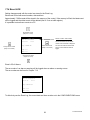
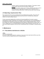
7.10 Filling the hopper
MANUAL FILLING
The control will automatically detect when the hopper is being manually filled.
During the time that the hopper is being filled, the TrueFeed is feeding with a fixed RPM; this means that the
unit is running temporarily volumetric. As soon as the hopper is filled, the TrueFeed immediately reverts to
working gravimetric.
AUTOMATIC FILLING (optional)
Introduction
Conair Truefeed feeders are capable of handling a variety of dry materials. Three (3) different filling systems
are available, depending on the material properties.
-The Conair Ejector (ME) system for dust-free or nearly dust-free materials.
-The Conair Vacuum (MV) system for materials that are NOT entirely dust free.
-The Conair (EX) loading system for use with an alternative hopper loader that includes a support frame and
surge hopper.
The ME, MV and EX systems are driven by low-pressure compressed air and mounted directly on top of the
hopper lid of the Conair feeder. The TrueFeed controls the operation of the ME, MV and EX systems.
All parts are aluminum or stainless steel and are virtually maintenance-free. Only the filter on the ME and MX
systems need to be cleaned periodically. To increase reliability and safety, there are no moving parts except
for the pneumatically-operated closing valve of the MV system and the knife gate of the EX system. ME hopper loader
How the ME works
The ME system blows the material from a bag, drum or container into the
hopper of the feeder. The hopper lid of the housing has a simple and easy-toclean dust filter to keep any dust particles in the hopper. The system is
triggered by the filling start weight (CONFIGURATIONS menu). This
parameter also generates a low-level alarm if the hopper is empty. For
installation instructions, see Appendix E entitled, ME Hopper Loader
Installation.
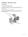
How the MV works
The MV system uses a 3-stage vacuum generator driven by compressed
air to create a vacuum that conveys material into a chamber that closes.
Once the chamber is filled with material, the cone that closes the chamber
will open and the material will be discharged into the hopper. The system
is equipped with a filter to ensure that the finest particles (> 5 micron) stay
in the system and are not released into the atmosphere. This makes the
MV system the most practical and user-friendly system for both powders
and granules. For installation instructions, see Appendix F entitled, MV
Hopper Loader Installation.
30
MV hopper loader
TrueFeed manual
How the EX (support frame for external hopper loader) works
The function of the support frame is to use an alternate hopper
loader in combination with the TrueFeed. The support frame is
equipped with a knife gate valve for filling the hopper. The valve
is normally-closed. If the filling start level is reached
(default 1.7 lb {800 g}) the valve opens and the hopper is filled until
the EX-H level (default 5.5 lb {2500 g}). The valve will then close
automatically. The support frame works independently from the
hopper loader. If for some reason the hopper weight reaches the
EX-HH level a warning will be displayed. This can happen if the
valve does not close, for example.
Surge hopper for
loader
EX hopper loader
support frame
Contact Conair for appropriate loader sizing to your surge hopper.
Do not remove the dispensing unit, surge bin, loader or
feeder hopper before the compressed air of the
knife gate valve has been disconnected and
the “Stop” button has been pressed. The knife
gate can still energize causing serious
personal injury.
It will be necessary to use a customer specific
surge hopper between the hopper loader and the
support frame for proper mounting.
1
2
3
4
31
Knife gate valve
Cylinder for open/close the valve
Solenoid valve
Connection Nuts (M10) for hopper loader mounting
TrueFeed manual
General
The hopper loader is only activated when the motor is On .
Emergency stop. To stop the hopper loader during production, go to the HOPPER LOADER menu and
switch the ME, MV or EX system to “OFF”.
Hopper loader settings
This part of the manual describes how to configure the hopper loader. For further technical information about
the hopper loader consult the specific hopper loader manual and Appendix E and F.
There are four (4) ways to fill the hopper:
1. Manually
2. Automatically with the ME hopper loader
3. Automatically with the MV hopper loader
4. Automatically with the EX external hopper loader in combination with the support frame
Manual
Open the hopper lid and fill the hopper by hand. (filling will be detected automatically)
The message “Low hopper level” appears when the hopper is empty.
(Default 1.5 lb {700 g} In CONFIGURATIONS menu)
ME hopper loader (Conair hopper loader operated by compressed air)
ME FILLING SYSTEM
ME system :
OFF/ON
Fill time :
30 sec
Alarm time :
31 sec
Alarm mode :
OFF/ON
Manual fill:
NO/YES
ME system:
Fill time:
Alarm time:
Alarm mode:
Manual fill:
Highlighted Parameters are factory settings.
Switch ON / OFF the ME hopper loader system
Fill time [sec.], during this time the system blows material into the hopper of the
dispensing unit.
Fill Alarm [sec.], if the hopper weight is not above the 1.7 lb {800 g} within this
time, an alarm will activate. The alarm time can not be set lower than the fill time.
ME hopper loader is ON / OFF during fill alarm.
ON
= ME Hopper loader stays activated during a filling alarm.
OFF
= ME Hopper loader will be deactivated during a filling alarm.
Yes = starting filling immediately;
No = stop filling immediately
Only visible with the control in STOP mode.
The manual filling function can be used to fill the hopper before the start of
production, for example.
MV hopper loader (Conair hopper loader operated by vacuum)
MV FILLING SYSTEM
MV system
:
OFF/ON
Fill time
:
20 sec
Empty time :
05 sec
Fill cycles :
3 x
Alarm cycles:
10 x
Alarm mode :
OFF/ON
Manual fill:
NO/YES
MV system:
Fill time:
Empty time:
Fill cycles:
Alarm cycles:
Alarm mode:
Manual fill:
Switch ON / OFF the MV hopper loader system
Fill time [sec.], during this time the MV system conveys material into the vacuum
chamber.
Empty time [sec.], during this time the cone that closes the chamber will open and
material falls down into the hopper of the TrueFeed.
Number of extra fill cycles after the hopper weight is above the 1.7 lb {800 g} again
Number of idle fill cycles before a fill alarm. The number of alarm cycles needs to be
more than the number of Fill cycles.
MV hopper loader is ON / OFF during fill alarm.
ON
= MV Hopper loader stays activated during a filling alarm.
OFF
= MV Hopper loader will be deactivated during a filling alarm.
Yes = starting filling immediately;
No = stop filling immediately
Only visible with the control in STOP mode.
The manual filling function can be to fill the hopper before start of production, for
example.
Highlighted Parameters are factory settings.
32
TrueFeed manual
EX hopper loader (support frame for external hopper loader)
EX FILLING SYSTEM
EX system
EX alarm time
EX alarm mode
Manual fill
:
:
:
:
OFF/ON
31 sec
OFF/ON
NO/YES
EX system:
Alarm time:
Switch ON / OFF the Support frame system.
Fill Alarm [sec.], if the hopper weight is not above the filling start level within this
time, an alarm will activate.
EX hopper loader is ON / OFF during fill alarm.
ON
= The system stays activated during a filling alarm.
OFF
= The system will be deactivated during a filling alarm.
Yes = starting filling immediately;
No = stop filling immediately
Only visible with the control in STOP mode.
The manual fill function can be used to fill the hopper before the start of
production, for example.
Alarm mode:
Manual fill:
Highlighted Parameters are factory settings.
Output signals
During fill time there will be a 24VDC signal between connection 24 and 25 on the main board to activate the
pneumatic solenoid valve.
When the Fill Alarm is activated there will be a 24VDC signal between connection 22 and 23 on the main board
to activate the alarm light. The control itself sounds a beeping signal and the alarm LED will be illuminated.
GENERAL RECOMMENDATIONS FOR OPTIMAL HOPPER FILLING
To guarantee the optimal performance of the TrueFeed, it is important to use the correct rate of hopper filling.
The higher the output of the feeder, the more important becomes the rate of hopper filling.
During hopper filling, the electronics of the TrueFeed control senses automatically that the hopper is being
filled. This automatic filling detection is used for both the manual filling of the hopper and filling with an
automatic hopper loader.
During the time that the hopper is being filled, the TrueFeed is feeding with a fixed RPM. This means the unit
runs temporarily volumetric. As soon as the hopper filling is complete, the TrueFeed immediately reverts to
working gravimetric.
Because the TrueFeed is working volumetrically during hopper filling, Conair recommends reducing the
amount of filling cycles, by having the maximum time between a filling cycle and the next filling cycle. This can
be performed when using the correct settings for the “Filling start level” and the “Filling stop level”.
When the unit is started with the auto start function enabled and the unit is turned OFF and then ON again,
filling will start automatically if the hopper weight is too low.
Sight glasses
Filling start level
The moment when the automatic filling starts depends on the
entered start level:
Filling start: xxx gr.
Filling stop level
Filling stop level is determined by the entered fill time for the
ME-system:
Fill time: xxx sec
(CONFIGURATIONS menu)
For the MV-system:
Fill time: xxx sec
Empty time: xx sec
Fill cycle: …. x
(Hopper Loader menu)
Recommended settings for ME hopper loader:
33
TrueFeed manual
-For the Filling Start Weight, use a low filling start weight level as shown on the filling start weight on the
previous page, a high fill start weight level will increase the amount of filling cycles.
-Use a fill time long enough so that the material at least covers the sight glass in the back of the hopper.
Overfilling the hopper should be avoided.
Recommended settings for MV hopper loader
-For the Filling Start Weight use a low filling start weight level as shown on the filling start weight on the
previous page, a high fill start weight level will increase the amount of filling cycles.
-Use a fill time so that the vacuum chamber of the MV-Loader is almost completely filled.
Overfilling of the vacuum chamber should be avoided.
-The empty time is critical. Set the empty time for approximately two (2) seconds longer than the actual
(observed) empty time. An empty time setting that is too short can cause a decrease in the capacity of the MVhopper loader.
-For the amount of filling cycles, use an amount so that the material at least covers the sight glass in the back
of the hopper. Overfilling the hopper should be avoided.
Recommended settings for EX hopper loader (support frame):
-The volume of a standard hopper is 0.2ft3 {6 L}. To set the EX-H level (stop filling), Conair recommends using
a safety margin to prevent the hopper from overfilling.
- EX-H (g) = 5 (liter) x bulk density (g/L)
For example: If the bulk density = 700 g/L, the EX-H should be set to 700 x 5 = 3500 g (7.7 lb).
The EX-HH (g) should be set higher, recommended 700 x 6 = 4200 g (9.3 lb).
Overfilling of the hopper should be avoided because it will effect the measurement.
7.11 Consumption
The Consumption menu will be visible when an automatic filling system is selected and enabled in the
HOPPER LOADER menu. Without use of a filling system, accurate working of the consumption registration is
not supported.
With the Consumption function, it is possible to view the total quantity of material dispensed by the TrueFeed.
The consumption is saved in the control’s memory and remains in the memory even when the unit is shut off or
unplugged.
To reset the consumption record, navigate to Reset and select “YES” and then press “Enter”.
CONSUMPTION
Batch:
x.xxx kg
Reset: NO/YES
Total:
Reset: NO/YES
x.xxx kg
Batch:
Reset:
Consumption of a batch (kg.)
Reset for batch consumption
Total:
Reset:
Total consumption (kg.) independent from Batch consumption
Reset of total consumption and Batch consumption
The consumption record is updated every 10 seconds.
34
TrueFeed manual
7.12 Alarms
GENERAL
To reset an alarm or warning press the “Stop” or “Menu” button.
When an error occurs using the TrueFeed, the control’s display will indicate an error code and description.
Along with the displayed error, an output contact will be switched.
The control itself will sound a beeping signal and the alarm LED will illuminate.
To distinguish between an alarm and warning:
Warning:
Warning output is ON, but the feeder continues running
(24 VDC contact, pin 22-23 of the main board will be active,
for example to activate the strobe light.)
Alarm:
Alarm output is ON and the feeder stops running
(Potential free contact, pin 26-27 of the main board will be active, for example to
stop the injection molding machine or extruder)
Free programmable errors can be configured to an Alarm or Warning.
To set the free programmable outputs to an alarm or warning, enter the ALARMS menu.
First the alarm history will be shown. The alarms and warnings will be stored here.
When you press the menu button again you will enter the Alarm CONFIGURATIONS menu.
Here you can set the alarm or warning output with
and pressing “Enter”.
ALARM HISTORY
All alarms and warnings will be stored in the alarm history.
• Navigate to the ALARMS menu
to scroll to the stored alarms (maximum of 50).
• Press
The alarm history can be reset by the Supervisor in CONFIGURATIONS menu by
• Master reset: Alarm
The following errors may be displayed:
Error
Code
00
01
02
03
05
06
07
Warnings
Low hopper level
Maximum deviation exceeded
Filling system unable to load material
Maximum RPM exceeded, change dosing
tool for higher capacity
Calibration, no weight change
Hi-Hi level
Minimum motor speed < 0.1 RPM
08
09
10
11
12
13
Alarms
Motor connection failure
Parameters damaged
Parameters set to factory defaults
Load cell calibration set to factory defaults
JOB and curve database initialized
Load cell connection failure
Material is below the hopper empty weight
The deviation of the material output is too high
Fill system is not working correctly
Calculated motor speed is too high
No weight change while calibrating
Hopper weight has reached the EX-HH level
Calculated motor speed is too low
Motor not connected / Motor or connection damaged
Check CONFIGURATIONS parameters
Check all parameter settings
Recalibrate the load cell
JOBs and Materials are reset
Load cell connection is not correct
35
TrueFeed manual
WARNINGS
All warnings are cleared automatically, except for Error code 05.
It is possible to cancel a warning, but when the error remains, the warning will return after 60 seconds. This
provides the operator enough time to solve the problem without having the alarm reactivate.
Error 00
“Low hopper level”
[free programmable]
If this warning appears the material in the hopper is below the hopper empty weight
1.5 lb {700 g}.
In CONFIGURATIONS menu this setting can be changed.
- Ensure there is enough material in the hopper.
- Check the hopper empty setting in CONFIGURATIONS menu.
- Ensure that the hopper loader is working correctly.
Error 01
“Maximum deviation exceeded”
[free programmable]
If this warning appears, the feeding output (grams/sec) is consistently not within set
percentage. See page 17 for more information.
Error 02
“Filling system unable to load material”
If this warning appears, the alarm time (ME hopper loader) or alarm cycles (MV
hopper loader) are exceeded.
- Ensure there is enough material.
- Ensure that the material is not stuck somewhere.
- Check the operation of the hopper loader.
- Check the hopper loader settings.
Error 03
“Maximum RPM exceeded, change feeding tool for higher capacity”
Calculated motor speed is higher than the maximum of 200 RPM.
- Check the material output at 200 RPM.
- Check the production settings.
- Increase the feeding time (if possible).
- Try another dispensing cylinder with higher output, for example an A20 feed screw.
Error 05
“Calibration, no weight change”
No weight change while calibrating (See Chapter 7.6).
- Ensure there is enough material in the hopper.
- Ensure that the material is not stuck in the dispensing cylinder.
- Ensure that the load cell is connected correctly.
- Check the weight data by performing a weight check (See Chapter 7.5).
- Ensure that there are no vibrations that may have influence.
- Check the rotation direction of the dispensing cylinder. Front view to the right
(Clockwise).
Error 06
“EX-Hi Hi level”
- Ensure that the knife gate valve is in the closed position.
- Check if the knife gate is sliding.
- Ensure that the parameters for EX-H level and EX-HH levels are set correct.
Error 07
“Minimum motor speed < 0.1 RPM”
Calculated motor speed is lower than the minimum of 0.5 RPM.
- Ensure there is enough material in the hopper.
- Check the production settings.
- Decrease the feeding time (if possible).
- Try another dispensing with lower output, for example a GL-cylinder.
- Check the rotation direction of the dispensing cylinder. Front view to the right
(Clockwise).
36
TrueFeed manual
ALARMS
Error 08
Error 09
Error 10
Error 11
Error 12
Error 13
“Motor connection failure”
Motor connection is not correct.
- Ensure that the motor is connected.
- Check cables and connectors for damage.
“Parameters damaged”
Some CONFIGURATIONS parameters are incorrect.
- Check the CONFIGURATIONS parameters.
“Parameters set to factory defaults”
All parameter settings are reset to factory defaults.
- Check all parameter settings.
“Load cell calibration set to factory defaults”
Load cell calibration is incorrect and has been reset to factory defaults.
- Recalibrate the load cell.
“JOBs and curve database initialized”
All JOBs and materials are reset.
- Make new material calibrations and Jobs.
“Load cell connection failure”
-Load cell connection is not correct.
-Load cell connector is not connected to the control.
7.13 Files
In this “File manager” menu, files (JOBs and Material curves) can be searched, renamed and deleted.
When entering the file manager menu, two file types can be selected:
-Material (material calibrations)
-JOBs (Production JOBs)
After confirming, the file list will be shown. Now you can search for files, rename or delete them.
If the JOB or Material curve you are searching for is not in the list, fill in the first letter(s) or complete name
of the JOB or Material curve and press “Enter”. Now a filtered list appears. To go back to the main list, fill in the
selection spaces and press “Enter”.
It is also possible to fill in the Job or Material curve immediately in the File Manager and press “Enter. To clear
the description, fill in the selection with spaces or select an empty JOB or material out of the list and press
“Enter”.
Search:
Delete:
Rename:
= Scroll through the files.
= Delete a file, press “Enter” to confirm.
= Rename a file, press “Enter” to confirm.
37
TrueFeed manual
7.14 Event LOG
Setting changes made with the control are stored in the Event Log.
Each event is filed with record number, date and time.
Approximately 7,000 events will be stored in the memory of the control. If the memory is filled, the latest event
will be logged and the oldest event will be deleted (first in / first out shift register).
It is possible to store these events to a PC.
Show latest events
(Steps of 1 event)
EVENT LOG
Record. number: 0000 of 0000
Rec nr: 0093/0093
01/01/06
Show previous events
(steps of 10 events)
The first number shows the record
number of the event that is displayed.
20:53
Log: ALARM NR.
Show latest events
(steps of 10 events)
Old: 8.0
The second number shows the total
amount of records/events that are
logged.
New: 0.0
Show previous event
(steps of 1 event)
Event LOG of Alarms
The error code of an alarm or warning will be logged when an alarm or warning occurs.
The error codes can be found in Chapter 7.12
EVENT LOG
Rec nr: 0078/0078
01/01/06
20:53
Log: COLOR PCT
Old: 2.0%
New: 1.8%
To effectively use the Event Log, the correct date and time must be set in the CONFIGURATIONS menu.
38
TrueFeed manual
8. System performance
System performance can be characterized by the time it takes the unit to reach the desired set point, the
accuracy of the set point and the consistency of the material output.
The algorithm is self-adjusting to the conditions and because the conditions vary, it cannot be predicted how
long it will take the unit to adjust itself and reach a set point with certain accuracy.
The following variables influence system performance:
Material properties. Easy flowing, non-sticky and non-static material that comes in the form of small granules
or powder can be dosed very accurately and consistently. The accuracy and consistency of the material output
drops with increased granule size. However, this is only a problem with extremely low outputs.
Periodical cleaning of the dispensing cylinder and seals is required for proper operation.
Extreme vibrations and shocks influence the system’s performance noticeably. Normally, the system will be
able to compensate for vibrations and shocks.
The TrueFeed algorithm needs a certain time to weigh material loss and adjust the RPM accordingly. This time
depends largely on the set point and the above mentioned three variables. The system constantly adjusts itself
to reach the best possible accuracy for current conditions. Over time it can reach an accuracy within ± 1%.
Under “normal” circumstances the unit will be more accurate than 10% after the first adjustment of the RPM.
Before the unit makes its first RPM adjustment it may be running already very close to the desired set point
because it uses a cylinder and material reference system to determine the first RPM setting. This accuracy
however cannot be guaranteed because material properties can vary substantially from material to material.
With injection molding the shot-to-shot accuracy depends, besides the variables mentioned so far, on the shot
time. If large and heavy granules have to be dosed in a very short time this will influence the shot accuracy and
repeatability because one granule can make a difference of a few percent to the shot weight.
An unstable relay or tachometer signal has a negative effect on the accuracy, repeatability and speed of the
system because it will adjust to these parameter changes.
A long cycle time combined with low dosage per shot can result in a slow system.
8.1 Reset regulation
•
•
•
•
•
•
Changing one parameter during production will cause the TrueFeed to adjust to the changes, but it will
not reset the regulation totally.
Changing more production parameters during production within 10 seconds after each other will cause
the TrueFeed regulation to reset. This is necessary for the system to adjust quickly to large changes in
the settings.
Turning the power OFF and ON again will also cause the regulation to reset.
Motor OFF and ON again will only cause the regulation to pause. The start up RPM will be the same as
the last RPM before the stop.
Changing one parameter with the motor OFF causes total reset of the regulation.
With auto start = ON (CONFIGURATIONS menu) the motor follows the last status (motor Standby or
motor Stop status) and causes total reset of the regulation.
39
TrueFeed manual
9. Troubleshooting
Problem: The feeder does not come into specification or a maximum deviation alarm is activated.
Possible causes:
1. Ensure that all cables are connected correctly.
2. Ensure that the transport protection pin is removed from the load cell safety bolt.
3. Ensure that the hopper assembly is fixed tightly to the weighing platform and that the throat adaptor is fixed tightly
to the production machine.
4. Ensure that the dispensing cylinder is tightly fixed to the motor shaft.
5. Excessive build-up of material on the dispensing cylinder may have affected proper feeding.
To avoid this, be sure that the seals and dispensing cylinder are clean.
6. Ensure to remove any tension on the cables connected to the weighing platform.
7. Use the weight check function with the reference weight to determine the correct function of the weighing system.
8. If the weight check gives the correct result, ensure that the material flow into the cylinder has not been blocked.
9. Another cause may be an obstruction to the weighing system. Ensure that there is at least ≈ 0.04 in {1mm} space
between all the pointed screws on the load cell frame or platform and that there is no material or dirt blocking the
movement.
10. In case of a water-cooled throat adaptor, ensure there is no material build up around the dispensing cylinder and
the water-cooled pipe that can obstruct the free movement of the weighing system.
11. Ensure that the input signal is stable.
12. If none of the above causes the problem, recalibrate the system and attempt the weight check again.
Problem: The feeder does come into specification but seems to be slow.
Possible causes:
1. Extreme vibrations and shocks to the system.
2. Extremely low setpoint. See Chapter 8, SYSTEM PERFORMANCE for more information.
3. Ensure that the automatic hopper hoses are connected properly.
Problem: The input/start-signal is connected but the unit does not recognize the start signal.
Possible causes:
1. Ensure that the correct wires are connected for potential free contact, potential contact or tachometer. Also check
if the (+) and (–) sides of the wiring are connected correctly.
[See chapter 6.5, 7.4 and Appendix B for the Wiring diagram.]
2. The earlier series control does need a different wiring diagram than the one printed in this manual. The wiring
diagram for main boards with the code MVC000BA02 (this code is printed on the main board) can be sent by
Conair on request.
3. Automatic fuse is activated, this can happen when there was a short-circuit at the input connection. To deactivate
the automatic fuse, the control needs to be turned OFF for a period of time and ON again. Check and repair any
short-circuits before cycling the feeder’s power.
Problem: The hopper weight is not stable.
Possible causes:
1. Ensure that the weighing signal is not influenced by external circumstances, for example that the load cell cable
passes near to electromagnetic fields or electro motors.
2. Extreme vibrations and shocks to the system.
3. Ensure that there is no obstruction to the weighing frame.
4. Ensure that the automatic hopper hoses are connected properly.
40
TrueFeed manual
APPENDIX A: TrueFeed Print View
Ribbon cable
connection between
terminal and mainboard
Terminal (display)
Ribbon cable
connection between
mainboard and load
cell board
Load cell board
1) Processor board
Incl. Mac-address
2) External terminal
connection
3) Connection to PC
or Network TCP/IP
4) Inputs
5) Motor
6) Outputs
41
7) Power supply
TrueFeed manual
Important note:
The maximum total output power may be 12 Watt (Valve output + alarm output)
- Valve output for hopper loader (Solid state 24VDC/0.5 A)
- Warning output (Solid state 24VDC/0.5 A)
- Potential free relay (normally open) output for alarm level (max. 230Vac/30Vdc, 5A)
- Potential free relay (normally open) output for running contact (max. 230Vac/30Vdc, 5A)
This contact will be closed simultaneously when the motor of the dosing unit is running.
APPENDIX B: TrueFeed Wiring Diagram
42
TrueFeed manual
APPENDIX C: TrueFeed Technical Specifications
Controls:
Set and actual % setting for injection molding and extrusion
Extrusion control by relay or tachometer
Injection molding control
Automatic metering time synchronization or by manual timer
Manual speed and time setting
Speed:
Manual setting from 0.1 to 200 RPM max, in increments of 0.1 RPM.
Time:
Manual settings from 0.1 to 999 sec in increments of 0.1 sec.
3 keyboard user levels
Integrated hopper loader control
Monitoring/System Information/External communication
128 x 84 full graphic LCD front display with integrated backlight.
Man/Machine interface:
Using full language command structure
External Communication:
PC link using TCP/IP internet protocol; optional RS232 or 485 available
Alarm:
2 user alarm levels
Specifications/Standards & Directives/ Technical data:
Power supply:
Operating power from 80 VAC to 260 VAC, 50 and 60 Hz
by integrated automatic voltage selector
Power consumption:
80 Watt maximum
Stepper motor:
(1.8 degr/step) max 2A or 4A (high output) at 40 Volt.
Operating Temperature:
-4° to +158° F {-20° to +70° C}.
Load cell and electronics:
20 bits A/D resolution with a full digital filtering
Input signal(s):
Injection molding:
Extrusion:
Start/Stop trigger input, potential free or 24VDC*
Start/Stop trigger input, potential free or 24VDC*
Tachometer input 0 to 30VDC
* Note potential contact
Guaranteed OFF:
0-8VDC
Guaranteed ON:
18-30VDC
Output(s):
-Stepper motor max. output 2A or 4A (high output) at 40VDC
-Solid state 24VDC/0.5 A output for valve hopper loader
-Solid state 24VDC/0.5 A output for external warning
-Relay for alarm level
(max. 230VAC/30VDC, 5A)
-Relay for running contact
(max. 230VAC/30VDC, 5A)
-Maximum total output power: 12 Watt (Valve output + alarm output)
Standard Directives:
Protection class: IP-50
According to CE standards:
EN50081-2 (HF radiation industry)
EN50082-2 (HF immunity industry)
Safety
•
•
In case of overload due to short-circuit or incorrect connection, the power supply automatically shuts down.
Opto insulated start input for connection to production machine.
Machine connection flange:
Standard flange NSt40-throat adaptor with cleaning opening.
Inlet/outlet ø 1.9 in / ø 1.5 in {ø50mm / ø40mm}, steel epoxy coated RAL 3002
Loadframe:
- Balance frame:
- Weighing frame:
- Load cell :
Steel, epoxy coated RAL 3002
Aluminum, epoxy coated RAL 9005
Nominal Load: 44 lb {20 kg}
Temp. compensated
Temp. range: -4° to 140° F { -20° to 60° C}
Protection level: IP63 EN60529
Optional parts
•
12 liter hopper stainless steel.
•
Flange type NSt90 with cleaning opening and inlet/outlet Ø1.9 in/Ø3.5 in {Ø50 mm/ Ø90 mm}, steel epoxy coated.
•
Water-cooled flange BH(A) inlet/outlet Ø1.9 in/Ø1.9 in {50 mm/50 mm} stainless steel ANSI 304.
•
Water-cooled flange PHA inlet/outlet Ø3.9 in/Ø3.9 in {100 mm/100 mm}
•
Hopper loader type ME
•
Hopper loader type MV
•
Hopper loader type EX
•
Mixers
•
External Alarm Flash light
•
External Alarm Siren
43
TrueFeed manual
APPENDIX D: TrueFeed Dimensions
44
TrueFeed manual
APPENDIX E: ME Hopper Loader
1. Description
1.1 What is the ME-Hopper loader?
The ME system blows material from a bag, drum or container into the hopper of the TrueFeed.
The hopper lid of the housing has a simple and easy-to-clean dust filter to keep any dust
particles in the hopper.
The hopper loader is controlled by the TrueFeed control.
When the ME system is installed on the TrueFeed, the system will be triggered by the filling
start weight (CONFIGURATIONS menu). The hopper empty weight generates a low-level
alarm if the hopper is empty.
ME Loader lid and filter
Tube support
Fixed hose
section
Flexible hose
section with ejector
pipe
45
TrueFeed manual
1.2 Overview of parts
46
TrueFeed manual
2. Installation
2.1 Mechanical installation
The hopper loader lid fits directly on the hopper of the TrueFeed.
To attach the ME hopper to the TrueFeed lid, quick release clamps on the hopper are used.
If the ME hopper loader is delivered subsequently instead of together with a TrueFeed unit the tube
support will need to be mounted to the frame of the TrueFeed.
2.2 Compressed air installation
The ME loader uses compressed air to convey material. The inlet for your compressed
air supply line is on the solenoid valve. The air connection diagram can be found on the valve’s
body.
1. Connect the compressed air to the ø0.31 x 0.24 in. {ø8x6 mm} compressed air connection on the solenoid
valve. The compressed air source must deliver a maximum of 58 - 116 PSI {4-8 bar} of clean, dry
(non-lubricated), air.
2. Make connections from the solenoid and the ejector pipe with the provided compressed air
tubing. Quick disconnect fittings are provided for these connections. The tubing should be cut to
length for maximum efficiency of the system. Use straight cuts to assure a good square tubing end.
CAUTION:
Be sure to provide hazard-free routing of the tubing, keep it away from hot or
moving surfaces and out of the way of personnel.
2.3 Connecting material line
The flexible hose will need to be attached over the inlet pipe of the ME hopper lid and ejector pipe.
Secure the hose with a hose clamp.
For TrueFeed: The flexible hose needs to be attached to the tube support
Secure the hose with a hose clamp.
Use the shortest possible length, to avoid wasting compressed air energy.
IMPORTANT: The material line should be as straight as possible.
Avoid loops and S-curves in flexible hose. This can affect conveying
performance.
Additional parts when field installing ME-loader to the TrueFeed:
- Short piece curved material hose (function = flexible joint between load cell and frame)
- Tube support
47
TrueFeed manual
2.4 Electrical installation
Solenoid valve
The solenoid valve needs to be connected to the control of the TrueFeed.
The wiring diagram for this connection is located in Appendix B.
3. Operation
3.1 How it works
The ejector pipe is located near the material supply and creates a vacuum on its inlet
by compressed air. This vacuum pulls on the material source and begins a flow of material
through the ejector pipe. Once inside the ejector pipe, the material is then ‘pushed’ by
the compressed air through the flex hose, towards the hopper of the dosing TrueFeed.
Once inside the hopper, the compressed conveying air is separated from the conveyed
material by a combination of gravity and the filter located on top of the loader. The
filter is a stainless steel perforated plate with ø0.07 inch {ø2mm} holes, plus an additional filter cloth.
3.2 Setting filling time and filling alarm
For the TrueFeed unit, the filling time and filling alarm need to be set. See section 7.10.
Filling time
Function:
When it is detected that the hopper is running empty the filling system/solenoid valve is switched
on. The filling time determines the duration of filling after the empty level is crossed again by filling
of material. This means that if the filling time is set to zero the loading system will only switch on
when the actual material level is under the empty level. When the filling time is set to 15
seconds the loading system will continue to convey material for 15 seconds after the empty level
is crossed.
Setting:
The filling time setting depends on several parameters. It is advised to start with 30 seconds and
adjust the time if necessary.
Filling alarm
Function:
The function of the filling alarm is to warn the operator that the hopper is not being filled even when
the hopper loader system is switched on. An empty material drum or loss of air pressure are
possible causes of a filling alarm.
Setting:
The filling alarm should be set longer then the filling time.
48
TrueFeed manual
3.3 Adjusting Compressed air flow
Adjusting compressed air flow
It is advised to use a flow regulator for the compressed air (not included).
The air flow will determine how much material will be transferred and how fast the TrueFeed will
be replenished with material, with each loading sequence.
Conair recommends adjusting the air setting to its lowest possible level in order to conserve compressed air
energy. Parameters such as distance, material line bends, the flow characteristics of the material
and vertical rises in the flex hose all play a part in finding the proper setting. Trial and error settings over
several loading sequences will work best to determine the correct air level. Too low of a setting may not move
material effectively enough to satisfy demands cycle after cycle. Too much air will waste energy and cause the
filter on the lid to prematurely blind in an attempt to evacuate excess air.
3.4
Weight level Adjustment
See Chapter 7.10 of the TrueFeed manual for adjustment of the “filling start” weight level and “hopper empty”
weight level.
4. Maintenance
4.1 Preventative maintenance schedule
• Daily
Clean the conveying filter.
If you are running a dusty material or regrind you may need to check and
clean the filter more often. The filter should be cleaned whenever you
change materials.
49
TrueFeed manual
5. Troubleshooting
5.1 Conveying problems and solutions
6. Technical specifications
50
TrueFeed manual
APPENDIX F: MV Hopper Loader
1. Description
1.1 What is the MV-Hopper loader
How the MV works
The MV system uses a 3-stage vacuum generator driven by compressed air to create a vacuum that
draws material into a chamber that closes. Once the chamber is filled with material, the cone that
closes the chamber will open and the material will be discharged into the hopper. The system is
equipped with a superior filter to ensure that the finest particles (> 5micron) stay in the system and
are not released into the atmosphere. This makes the MV system the most practical and user-friendly
system for both powders and granules. The hopper loader is operated by the TrueFeed control.
When the MV system is installed on the TrueFeed, it will be triggered by the filling start weight
(CONFIGURATIONS menu). The “hopper empty weight” generates a low-level alarm if the hopper is
empty.
51
TrueFeed manual
2. Overview of parts
52
TrueFeed manual
2.1 Tube support
When the MV-Hopper loader is supplied together with the TrueFeed, a tube support is installed on the
load frame (see picture below). If the MV-hopper loader is delivered subsequently to a TrueFeed, the
user needs to install the tube support. The tube support needs to be installed with two bolts on the
frame of the TrueFeed.
Function of the tube support
The tube support is needed to create a loop in the flexible hoses shown in the picture below. The loop
is necessary for a proper weigh function of the TrueFeed. The length of the loop should not be
changed. The 118 in. {300 cm} hose length must have a 34.7 in. {95 cm} loop. (for 6 L and 12 L
hoppers)
53
TrueFeed manual
3. Installation
3.1 Mechanical installation
1. If the MV-loader is delivered subsequently instead of together with a TrueFeed, the tube
support needs to be mounted on the frame of the TrueFeed.
2. Install the MV-loader assembly on the TrueFeed. The MV-loader lid fits directly on the hopper
on the TrueFeed. Use the quick release clamps on the TrueFeed hopper to mount the MVloader.
3. Connect an ø0.31x0.23 in. {ø8x6 mm} compressed air hose from the compressed air source to
the pressure regulator and from the pressure regulator to Connection 1 on the solenoid valve.
Attach the ø0.31x0.23 in. {ø8x6 mm} compressed air source from Connection 2 of the solenoid
valve to the connection on the top flange of the MV-hopper loader. The ø0.31x0.23 in.
{ø8x6 mm} compressed air source hose must be first connected to the tube support and from
the tube support to the top flange of the MV-hopper loader.
4. Connect the material transfer hose to the inlet connection on the MV-hopper loader and to the
air wand. The material line also needs to be connected to the tube support. Secure the hose
with provided clamps.
IMPORTANT:
Reduce the material transfer hose to the shortest possible length, to avoid wasting
compressed air energy. The material line should be as straight as possible. Avoid
loops and S-curves in flexible hose, this can affect conveying performance.
3.2
Electrical installation
Solenoid valve
The solenoid valve needs to be connected to the control of the TrueFeed. If the hopper loader is
delivered together with a dosing unit, the electrical connection is already made. The wiring
diagram for this connection can be found in this user manual.
54
TrueFeed manual
3.3 Compressed air requirements
The MV-loader uses compressed air to create vacuum. The compressed air source must deliver a
maximum of 58-116 PSI {4-8 bar} of clean, dry (non-lubricated), air pressure.
Make connections from the solenoid and the ejector pipe with the provided compressed air
tubing. Quick disconnect fittings are provided for these connections. The tubing should be cut
to length for maximum efficiency of the system. Use straight cuts to assure a good square
tubing end. Ensure everything is connected firmly.
CAUTION:
Be sure to provide hazard-free routing of the tubing, keep it away from hot or moving surfaces and
out of the way of personnel.
3.4 Air wand adjustment
The air wand can be adjusted in three different positions, which position is required depends on the
properties of the material to conveyed. The adjustment of the wand regulates the mixture of
conveying air and material to be conveyed.
Position 1: Standard position
Position 2: Additional conveying air
Position 3: Maximum conveying air
Conair recommends starting with Position 1.
If there is no or minimal material conveying, the air wand can be adjusted to Position 2. The larger the
granule, the less extra air is needed for conveying.
When Position 2 or 3 is used when Position 1 is sufficient, it can result in poor operation:
- Reduced capacity
- More frequent filter clogging.
55
TrueFeed manual
4. Operation
4.1 Starting up the MV-Hopper loader after installation
For safety reasons, the hopper loader is only activated when the TrueFeed is in the START mode. To
deactivate the hopper loader, in case of emergency, press the “STOP” button on the control. Be
aware that the TrueFeed will also deactivate.
1. Adjust the pressure regulator to a minimum of 58 PSI {4 bar} and adjust to a higher value if
necessary.
2. Adjust the air wand to the correct position, most applications start with Position 1.
3. Determine the correct filling level for the MV hopper loader - see Chapter 7.10 for adjustment of the
“filling start” weight level and “hopper empty” weight level.
4. For all TrueFeeds, the filling time, empty time, amount of filling cycles and filling alarm parameters
have to be set in the control by the user. See Chapter 7.10 for more information.
Filling time [sec.]
During this time the MV system sucks material into the vacuum chamber.
The filling time setting depends on several factors. Conair recommends
starting with the default of 20 seconds and adjust if necessary. For maximum
performance, use a filling time that will fill the loader until it is covering the
sight glass completely. A longer filling time will affect optimum performance.
Empty time [sec.]
During this time the cone that closes the chamber will open and material falls
down into the hopper of the dosing unit. Conair recommends starting with the
default of 5 seconds which will be sufficient in most applications. In case of
poor flowing material this time will need to be extended. A longer empty time
than necessary will affect optimum performance.
Fill cycles [number]
Number of extra fill cycles after the material is above the empty level.
Example:
When the amount of fill cycles is set to “0” the MV-loader will perform filling
cycles until the material level is above the “empty level”. When the amount of
fill cycles is set to “1” the MV-loader will perform 1 extra filling cycle after the
material level is above the “empty level”. Conair recommends starting with
the default of 3 extra filling cycles, setting more filling cycles than necessary
will affect optimum performance.
56
TrueFeed manual
Alarm cycles [number]
Number of idle fill cycles before fill alarm will appear. The number of alarm
cycles needs to be more than the number of filling cycles.
Example:
If the amount of alarm cycles is set to 10 times, the MV-loader will try with 10
extra filling cycles to get material conveyed to the TrueFeed. If still no
material is conveyed after these 10 extra cycles an alarm will be activated.
4.2 Adjusting compressed air flow
The compressed air flow can be regulated with the provided pressure regulator. The air flow will
determine how much material will be transferred and how fast the TrueFeed will be filled with
material, with each loading sequence.
Conair recommends adjusting the air setting to its lowest possible level in order to conserve
compressed air energy. Parameters such as distance, material line bends, the flow characteristics of
the material and vertical rises in the flex hose all play a part in finding the proper setting. Trial and
error settings over several loading sequences will work the best to determine the correct air level. Too
low of a setting may not move material effectively enough to satisfy demands cycle after cycle. Too
much air will waste energy and cause the filter to prematurely blind in an attempt to evacuate excess
air.
5. Maintenance
5.1 Preventative maintenance schedule
• Daily
Clean the conveying filter.
If you are running a dusty material or regrind you may need to check and clean the filter more often.
The filter should be cleaned whenever you change materials.
57
TrueFeed manual
5.2 Cleaning/Disassembling the loader
The MV-loader assembly can easily be disassembled for cleaning without tools.
To clean the MV-Loader:
1. Disconnect the main power and compressed air sources.
2. Remove the material transfer hose from the inlet pipe of the loader.
3. Disconnect the three (3) quick release clamps on the inlet flange
4. Disconnect the ø0.23x0.16 in. {ø6x4 mm} compressed air hose from the push in fitting in the lid
(Pictured below).
5. Remove the stainless steel filter screen.
6. Remove the inlet flange.
7. Remove the sight glass.
8. If previous material is a “dirty” material, store the filter until the next run of that color and use extra
filters. Otherwise use clean shop air to blow out the entrapped dust remaining in the filter.
9. Clean the hopper assembly by wiping it clean with a clean dry cloth.
10. Clean the material transfer hose(s) and air wand. If previous material is a “dirty” material store the
soiled parts until the next run of that color and use extra parts for material transfer.
11. Re-assemble the loader parts in the reverse order.
•
Ensure that before replacing the sight glass, no material is on the rubber o-rings at the bottom
and upper side of the sight glass.
•
Reconnect the compressed air tube (picture below)
•
Replace the filter in the correct direction, fine side down, rough side up.
58
TrueFeed manual
6. Troubleshooting
6.1 Conveying problems and solutions
59
TrueFeed manual
7. Technical specifications
60
TrueFeed manual
APPENDIX G: We’re Here to Help
Conair has made the largest investment in customer support in the plastics industry. Our service experts are available to
help with any problem you might have installing and operating your equipment. Your Conair sales representative also can
help analyze the nature of your problem, assuring that it did not result from misapplication or improper use.
How to Contact Customer Service
To contact Customer Service personnel, call:
Note: Normal operating hours are 8:00 AM - 5:00 PM (EST). After hours emergency service is available at the
same phone number.
From outside the United States, call: 814-437-6861
You can commission Conair service personnel to provide on-site service by contacting the Customer Service
Department. Standard rates include an on-site hourly rate, with a one-day minimum plus expenses.
Before You Call...
If you do have a problem, please complete the following checklist before calling Conair:
Make sure you have all model, serial and parts list numbers for your particular equipment. Service
personnel will need this information to assist you.
Make sure power is supplied to the equipment.
Make sure that all connectors and wires within and between control systems and related components
have been installed correctly.
Check the troubleshooting guide of this manual for a solution.
Thoroughly examine the instruction manual(s) for associated equipment, especially controls. Each
manual may have its own troubleshooting guide to help you.
Check that the equipment has been operated as described in this manual.
Check accompanying schematic drawings for information on special considerations.
61
TrueFeed manual
Equipment Guarantee
Conair guarantees the machinery and equipment on this order, for a period as defined in the quotation from date
of shipment, against defects in material and workmanship under the normal use and service for which it was
recommended (except for parts that are typically replaced after normal usage, such as filters, liner plates, etc.).
Conair’s guarantee is limited to replacing, at our option, the part or parts determined by us to be defective after
examination. The customer assumes the cost of transportation of the part or parts to and from the factory.
Performance Warranty
Conair warrants that this equipment will perform at or above the ratings stated in specific quotations covering
the equipment or as detailed in engineering specifications, provided the equipment is applied, installed, operated
and maintained in the recommended manner as outlined in our quotation or specifications. Should performance
not meet warranted levels, Conair at its discretion will exercise one of the following options:
Inspect the equipment and perform alterations or adjustments to satisfy
performance claims. (Charges for such inspections and corrections will be waived unless failure to meet
warranty is due to misapplication, improper installation, poor maintenance practices or improper operation.)
Replace the original equipment with other Conair equipment that will meet
original performance claims at no extra cost to the customer.
Refund the invoiced cost to the customer. Credit is subject to prior notice by the customer at which time a
Return Goods Authorization Number (RGA) will be issued by Conair’s Service Department. Returned
equipment must be well crated and in proper operating condition, including all parts. Returns must be
prepaid.
Purchaser must notify Conair in writing of any claim and provide a customer receipt and other evidence that a
claim is being made.
Warranty Limitations
Except for the Equipment Guarantee and Performance Warranty stated above, Conair disclaims all
other warranties with respect to the equipment, express or implied, arising by operation of law, course of
dealing, usage of trade or otherwise, including but not limited to the implied warranties of
merchantability and fitness for a particular purpose.
62
TrueFeed manual
APPENDIX H: TrueFeed Quality Checklist
Date of production
Conair order number
Control serial number
Software version
Motor serial number
Unique ID code
: …………………
: …………………
: …………………
: …………………
: …………………
: …………………
Check original order with internal packing list
Order code : ……………………………………………………………………
Cylinder check
Fill in the type of cylinder ………
Fill in the cylinder length ………in {mm}
Check for cylinder wrench
Stepper motor check
Direction motor rotation from rear view ( motor number side )
Check if cable and connector are fastened well.
Check sealing.
Hopper check
Check hopper edges for blurs
Check lid for sharp edges
Check slide valve
Check sealing ring
Check sight glasses
Throat adaptor check
Check sight glass and the inside if everything is clean
Check fitting of the feeding house
Check curled knob length and fitting
Complete unit check / Functional test at least 4 hours
Perform load cell calibration
Perform a weight check with the 1.1 lb {500 g} reference weight
Perform a Master Reset ALL [CONFIGURATIONS menu]
Check internal File System by making a JOB [PRODUCTION menu]
Perform functional test with motor (200 rpm)
Check timer, tachometer and relay
Power cable ……… /warning label
Check input cable/ warning label
Check appropriate users manual
Check (optional) alarm flash light
Check (optional) valve output
Automatic hopper loader check (Optional)
No automatic hopper loader supplied
ME hopper loader
MV hopper loader
EX hopper loader
63
TrueFeed manual