1
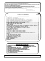
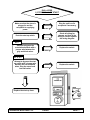
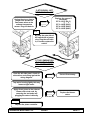
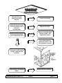
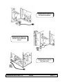
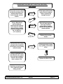
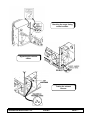
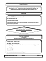
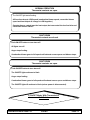
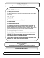
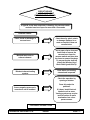
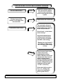
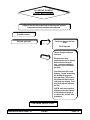
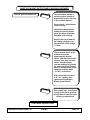
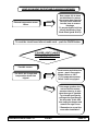
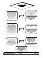
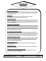
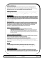
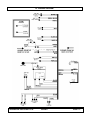
FOR INSTALLERS AND SERVICE TECHNICIANS ONLY
PELLET
STOVE
SERVICE
MANUAL
Sherwood Industries Ltd. Duplication of this document is prohibited. All rights reserved.
August 2003
C-10097
This is a service guide designed by SHERWOOD INDUSTRIES LTD.
We hope this manual will assist you to identify and correct operational concerns you might
experience in all ENVIROFIRE pellet stoves.
This service guide is designed for SERVICE TECHNICIANS AND INSTALLERS ONLY.
This guide is not to be used by the homeowner.
If after using this service manual and following our recommendations and the problem still
excists, please do not hesitate to call our technical department.
Technical Division
Sherwood Industries Ltd.
TABLE OF CONTENTS
PAGE
Timer Control………………………...…………………………………..……………………..…1
1) STOVE WILL NOT START………………………………..………………………………….1
2) STOVE WILL NOT OPERATE WHEN HOT…………………………….…..………………2
3) THE COMBUSTION (EXHAUST) BLOWER WILL NOT FUNCTION………………..….2
4) THE CONVECTION BLOWER WILL NOT FUNCTION PROPERLY…………………...3
5) THE AUGER MOTOR DOES NOT FUNCTION PROPERLY………………….………...5
6) DIAL-A-FIRE HAS NO EFFECT ON THE FIRE………………….……………….……….8
7) THE STOVE WILL NOT SHUT DOWN………………………………………….………….9
CIRCUIT BOARD…………………..…………………………………………………….……….10
1) MANUAL MODE, FACTORY SETTINGS, NO THERMOSTAT OR WALL SWITCH….10
2) HI/LO MODE, WITH THERMOSTAT OR WALL SWITCH………………………………..11
3) ON/OFF MODE, WITH THERMOSTAT OR WALL SWITCH…………………………..13
CIRCUIT BOARD CONTROLS………………………………………………………………….16
THERMOSTAT PIN SET-UP….……………………………………………………………….16
1) LIGHT #2 ON HEAT OUTPUT BAR FLASHING………………………………………...17
2) LIGHT #3 ON HEAT OUTPUT BAR FLASHING………………………………………...18
3) AUGER LIGHT FLASHES BUT AUGER MOTOR DOES NOT TURN AT ALL………..21
GENERAL………………………………………………………………………………………….22
1) THE IGNITOR DOES NOT WORK………………………………………………….……..22
2) THE STOVE KEEPS GOING OUT……………………………………………….………..23
COMPONENTS OF A PELLET STOVE………………………………………………………..24
FLAME CHARACTERISTICS……...……………………………………………………………26
WIRING DIAGRAMS……..……………………………………………………………………...27
GLOSSARY………………………………………………………………………………………..36
SUGGESTED TOOLS LIST
Cordless drill / Screwdriver
Magnehelic Pressure Gauge
Multimeter
Ratchet and Sockets: 1/4” to 5/8”
Open ended Wrenches: 1/4” to 1/2”
Electrical Tape
Screwdrivers (T20 TORX) Robertson, Straight Blade
Wire Cutters, Strippers, Crimpers and Needle Nose Pliers
Penetrating Lubricant (WD-40)
High Temperature Silicone (RTV) 500°F
1/4” Insulated connectors
SHERWOOD INDUSTRIES LTD.
ENVIRO
2003
DIAL-A-FIRE
1) STOVE WILL NOT START
If not
Make sure that the stove is
plugged in and the
receptacle is supplying
power.
Plug the unit in or fix
receptacle if necessary.
If not
Push the start up switch.
Does not start
Check all wiring for
damage and that all the
wiring is correct against
the wiring diagram.
EF 2
Attempt to bypass the
auto/manual switch with a
jumper wire between the
grey and black wires.
Replace the switch.
Starts
EF 3, 4, 5
Attempt to by pass the start
up switch with a jumper wire
between the red and white
wires. Plug the stove back
into wall outlet.
Replace the switch.
Starts
Replace the start up timer.
SHERWOOD INDUSTRIES LTD.
ENVIRO
PAGE. 1
2) STOVE WILL NOT
OPERATE WHEN HOT
Unplug the stove; place a
jumper wire across the
two brown wires on the
exhaust temperature
sensor. Plug unit back in.
If Runs
Replace the sensor if
necessary.
EF-2--120°F (49°C)
EF-3--140°F (60°C)
EF-4--120°F (49°C)
EF-5--120°F (49°C)
EF-2
By pass the auto side of
the switch with a jumper
wire. Plug the unit back
in, if it starts replace the
switch.
3) THE COMBUSTION
(EXHAUST) BLOWER
WILL NOT FUNCTION
Open the left side panel, check all
connections and wiring against the
wiring diagram.
Correct if necessary.
Tap motor housing lightly this may
loosen a tight motor.
Apply direct power to the exhaust
blower with a test cord, by
removing the two leads and
plugging the motor in directly.
Replace the blower
motor.
Does not run
EF-4, 5
Replace the phase controller.
SHERWOOD INDUSTRIES LTD.
ENVIRO
PAGE. 2
4) THE CONVECTION
BLOWER WILL NOT
FUNCTION PROPERLY
Check all the wires
against the wiring
diagram.
Apply direct power to the
convection blower with a
test cord.
See next page.
Correct if necessary.
Replace the blower.
Doesn’t run
Remove one of the wires
from the 160 °F (71°C)
temperature sensor.
If the convection blower
runs on high all the time.
If the blower shuts off
replace the 160° F (71°C)
fan temperature sensor.
If the motor is still running
on high, replace the fan
controller.
If the fan has a low pitched
rumble.
SHERWOOD INDUSTRIES LTD.
Replace the fan controller.
ENVIRO
PAGE. 3
Applying direct power to
the convection blower.
Bypassing the 200°F 93°C
manual reset temperature
sensor.
Applying direct power to
the auger motor.
SHERWOOD INDUSTRIES LTD.
ENVIRO
PAGE. 4
5) THE AUGER MOTOR
DOES NOT FUNCTION
PROPERLY
If NO see section #3 in this
manual.
Make sure that the
exhaust blower is
operating correctly.
Make sure the dial-a-fire is
turned to the “ON”
position.
Turn knob clockwise to
the “ON“ position.
Check to make sure all
wires are correct to the
auger motor, dial-a-fire,
vacuum sensor, 200°F
(93°C) temperature
sensor and the timing
control module.
Correct if necessary.
Replace the auger motor.
Using a test cord apply
direct power to the auger
motor. See previous page.
Doesn’t run
Check the vacuum hose to
make sure there are no
cracks or breaks.
IF THIS SENSOR HAS
BEEN TRIPPED FIND THE
REASONS FOR THE
OVER HEATING
BEFORE PUSHING
BUTTON IN.
Check to make sure that
the reset button on the
200° F (93°C) temperature
has not been tripped.
By pass the 200° F (93°C)
temperature sensor with a
jumper wire. See previous
page.
Replace the200° F (93°C)
temperature sensor.
If it works
CONTINUED ON NEXT PAGE
SHERWOOD INDUSTRIES LTD.
ENVIRO
PAGE. 5
AUGER MOTOR DOES NOT FUNCTION PROPERLY
CONTINUED
Check the vacuum switch
by placing a jumper wire
between the two blue
leads from the vacuum
switch.
Using a Magnehelic
pressure gauge,
disconnect the vacuum
hose from the exhaust
channel, these reading
should be greater than:
0.4” wc (EF 2-3).
0.2” wc (EF-4).
If the auger motor works
make sure the exhaust
motor is producing
enough vacuum.
If not
If over
Test the dial-a-fire; place
a jumper wire across the
(2) two pins on the timing
control module
The unit may require a
thorough cleaning.
If thoroughly cleaned.
Replace the combustion
exhaust blower.
Replace the vacuum
sensor.
If the auger motor cycles
very quickly, test the diala-fire.
Using a multimeter test
the dial-a-fire, the values
from this test should be
between 68k and 850k
plus or minus 10%.
Replace the Dial A Fire.
If all these procedures are
O.K. replace the augertiming module
SHERWOOD INDUSTRIES LTD.
ENVIRO
PAGE. 6
Checking the auger timing
control module.
Bypassing the vacuum
switch.
Testing the exhaust
vacuum.
SHERWOOD INDUSTRIES LTD.
ENVIRO
PAGE. 7
6) DIAL-A- FIRE HAS NO
EFFECT ON THE FIRE
EF 2, 3, 5
Test the dial-a-fire
potentiometer resistance
by placing the multimeter
leads into the leads of the
potentiometer.
Remove leads from the
timing control.
Low fire 800-900k ohms.
High fire 71-73k ohms.
EF 4
Low-Fire 800-900k ohms.
High fire 36.5k ohms.
Replace the potentiometer
or dial-a-fire.
Rear of the
control panel.
SHERWOOD INDUSTRIES LTD.
ENVIRO
PAGE. 8
7) THE STOVE WILL
NOT SHUT DOWN
Check all wiring to the
exhaust temperature
sensor, start-up switch
and the start up timer.
Correct if necessary.
EF 3, 4, 5
Disconnect one brown
wire from the exhaust
temperature sensor.
If the unit shuts down,
replace the exhaust
temperature sensor.
If the unit does not shut down test the switch.
If the unit starts without
pushing the start up
switch, test the 15
minutes start up timer.
The unit must be cold,
unplug the unit and then
plug it back in.
If the unit does not start
replace the switch.
Open the right hand side
panel. Remove the red
wire from the 15 minute
start up timer, unplug the
unit and then plug the
stove back in.
If the unit starts by itself
replace the (15) fifteen
minute timer.
EF-2
If the unit shuts down
replace the auto/manual
switch.
With one of the brown
wires from the exhaust
temperature sensor
disconnected.
EF-2
If the unit did not shut
down replace the wiring
harness.
Remove the gray wire
from the auto/ manual
switch.
SHERWOOD INDUSTRIES LTD.
ENVIRO
PAGE. 9
CIRCUIT BOARD
OPERATION
1) Manual Mode, Factory Settings, No
Thermostat or Wall Switch
START-UP SEQUENCE
(15 minutes)
Push the ON/OFF button to start.
The ON/OFF light turns on solid.
The ON/OFF lights starts to flash after the vacuum sensor has closed (approx. 15
seconds).
Auger light flashes:
- 3 seconds ON.
- 8 seconds OFF.
The combustion blower comes on at full speed.
The ignitor comes on.
The convection blower stays off.
The operator has no control over the start-up sequence. (The operator can press
and hold the manual feed button to run the auger continuously. The operator can
also pre-set the heat output setting for operation. When the unit reaches
operating temperature the heat output will go to that setting.)
The unit should light after 5 to 12 minutes.
Once the 120 °F (49 °C) exhaust temperature sensor closes, the Convection
blower will come on.
15 minutes after pushing the start button, the On/Off light changes to solid. This
signals that the unit is at operating temperature.
SHERWOOD INDUSTRIES LTD.
ENVIRO
PAGE. 10
Normal Operation
The operator can now set the heat output, low feed trim and whether the convection
blower is ON or OFF. (Please note: when the heat output is changed, the
combustion blower and convection blower speed change as well.)
Shut Down
Push the ON/OFF button to turn stove off.
All the lights will turn off.
The auger will stop feeding.
The combustion blower goes to full speed until the exhaust temperature sensor
opens, stopping all motors
2) HI/LOW Mode, With Thermostat or
Wall Switch
START-UP SEQUENCE
(15 minutes)
Thermostat contacts closed at time of start-up.
Push the ON/OFF button to start.
The ON/OFF light turns on solid.
The ON/OFF lights starts to flash after the vacuum sensor has closed (approx. 15
seconds).
Auger light flashes:
- 3 seconds ON.
- 8 seconds OFF.
The combustion blower comes on at full speed.
SHERWOOD INDUSTRIES LTD.
ENVIRO
PAGE. 11
START-UP SEQUENCE CONT.
The ignitor comes on.
The convection blower stays off.
The operator has no control over the start-up sequence. (The operator can
press and hold the manual feed button to run the auger continuously. The
operator can also pre-set the heat output setting for operation. When the
unit reaches operating temperature the heat output will go to that setting.)
The unit should light after 5 to 12 minutes.
Once the 120 °F (49 °C) exhaust temperature sensor closes, the convection
blower will come on.
15 minutes after pushing the start button, the On/Off light changes to solid.
This signals that the unit is at operating temperature.
Note: The circuit board can only be turned OFF during start-up if vacuum has
been established and the thermostat contacts are closed. The ON/OFF
light will continue flashing
START-UP SEQUENCE
(15 minutes)
Thermostat contacts open at time of start-up.
Same as “START-UP SEQUENCE (15 minutes)
Thermostat contacts closed at time of start-up.”
NORMAL OPERATION
Thermostat contacts are closed.
The ON/OFF light is solid.
Operator can now set; heat output, low feed trim and convection blower ON/OFF
(combustion blower, convection blower and heat output all change together.)
SHERWOOD INDUSTRIES LTD.
ENVIRO
PAGE. 12
NORMAL OPERATION
Thermostat contacts are open.
The ON/OFF light starts flashing.
All functions drop to LOW speed (combustion blower speed, convection blower
speed and heat output all change to LOW together.)
Operator has no control over the heat output, but can control the low feed trim and
convection blower ON/OFF.
SHUT DOWN
Thermostat contacts are closed.
Push ON/OFF button to turn stove off.
All lights turn off.
Auger stops feeding.
Combustion blower goes to full speed until exhaust sensor opens and blower stops.
SHUT DOWN
Thermostat contacts are open.
Push ON/OFF button to turn stove off.
The ON/OFF light continues to flash.
Auger stops feeding.
Combustion blower goes to full speed until exhaust sensor opens and blower stops.
The ON/OFF light will continue to flash (unless power is disconnected).
3) ON/OFF Mode, With Thermostat or
Wall Switch
SHERWOOD INDUSTRIES LTD.
ENVIRO
PAGE. 13
START-UP SEQUENCE
(15 minutes)
Thermostat contacts closed at time of start-up.
Push the ON/OFF button to start.
The ON/OFF light turns on solid.
The ON/OFF lights starts to flash after the vacuum sensor has closed (approx.
15 seconds).
Auger light flashes:
- 3 seconds ON.
- 8 seconds OFF.
The combustion blower comes on at full speed.
The ignitor comes on.
The convection blower stays off.
The operator has no control over the start-up sequence. (The operator can
press and hold the manual feed button to run the auger continuously. The
operator can also pre-set the heat output setting for operation. When the unit
reaches operating temperature the heat output will go to that setting.)
The unit should light after 5 to 12 minutes.
Once the 120 °F (49 °C) exhaust temperature sensor closes, the convection
blower will come on.
15 minutes after pushing the start button, the On/Off light changes to solid.
This signals that the unit is at operating temperature.
If the thermostat contacts are opened during start up the circuit board and all
motors turn OFF and the ON/OFF light remains flashing.
START-UP SEQUENCE
(15 minutes)
Thermostat contacts open when the ON/OFF button is pushed.
The circuit board will not turn on.
SHERWOOD INDUSTRIES LTD.
ENVIRO
PAGE. 14
NORMAL OPERATION
Thermostat contacts are closed.
Unit starts the start-up sequence.
After 15 minutes start-up, operator can set; heat output, low feed trim and convection
blower ON/OFF (combustion blower, convection blower and heat output all change
together).
NORMAL OPERATION
Thermostat contacts are open.
The ON/OFF light starts flashing.
All functions drop to LOW speed (combustion blower speed, convection blower
speed and heat output all change to LOW together).
Operator has no control over the heat output, but can control the low feed trim
and convection blower ON/OFF.
SHUT DOWN
Thermostat contacts are closed.
Stove will not shut off.
If you push ON/OFF button the circuit board will go through a start-up sequence (see
start-up section above).
SHUT DOWN
Thermostat contacts are open.
All lights turn off.
Auger stops feeding.
Combustion blower goes to full speed until exhaust sensor opens and blower stops.
SHERWOOD INDUSTRIES LTD.
ENVIRO
PAGE. 15
CIRCUIT BOARD CONTROLS
HEAT LEVEL (OUTPUT) LIGHTS – shows the heat setting that the stove is operating in.
lowest setting is at the bottom.
HEAT LEVEL SWITCH – press this button to set the heat level. The light will scale up
through the range then back to the lowest.
AUGER TRIM SWITCH – Press this button to choose between
three different ON times when the heat output in the low
setting. Only the bottom heat level light on shows that the on
time is set at 3 seconds ON (factory setting). Push the switch
and the lights change to the bottom and the top light being on,
this means the auger ON time has been increased to 4
seconds. Push the button again and the lights change to the
bottom and the second from the top position. The auger ON
time is now 2 seconds.
CONVECTION FAN SWITCH – press this switch to turn the
convection blower OFF, press again to turn the blower on to
the preset speed that corresponds to the heat level.
MANUAL FEED SWITCH – hold this button down to manually
run the auger continuously. The auger returns to automatic
when the switch is released.
ON/OFF SWITCH – push this switch to start or stop the unit
when the unit is operating in “manual” or HI/LOW thermostat
mode (ON/OFF is automatic once the stove has been started
once).
THERMOSTAT PIN SET-UP
CAUTION: The use of the thermostats with timers may result in the unit shutting off during
start-up. This may allow smoke to enter the house through the air wash system.
Jumper pins J9
ithe HI / LOW
mode
SHERWOOD INDUSTRIES LTD.
Jumper pins
in9 the ON /
OFF mode
ENVIRO
PAGE. 16
CIRCUIT BOARD
1) LIGHT #2 ON HEAT
OUTPUT BAR FLASHING
If light #2 on the heat output bar is flashing, the vacuum switch
contacts have been open for more than 15 seconds.
Possible causes:
Check hose for pinch points
or damage. Replace or reroute as required, blow out
vacuum hose.
Pinch, break or blockage in
vacuum hose.
Blocked hose barb on
exhaust channel.
Use a paper clip to clean out
hose barb or remove the
vacuum hose from the
vacuum switch and blow into
the hose to remove blockage.
To prevent further build up
install, the Windsor Hose
Barb Shield (part# 50-472).
Blocked exhaust/venting
system.
Have stove and venting
cleaned and inspected.
Check the operation by
opening a window.
Does this solve the
problem?
Severe negative pressure in
area where unit is installed.
If it does, install fresh air
intake to unit or room.
Venting system may require
vertical section to move
termination into a lowpressure zone.
CONTINUED ON NEXT PAGE
SHERWOOD INDUSTRIES LTD.
ENVIRO
PAGE. 17
LIGHT #2 ON HEAT OUTPUT BAR FLASHING CONTINUED
Bypass the vacuum switch, if
this corrects the problem
check for above problems
before replacing the vacuum
switch.
Vacuum switch failure.
Damage to gray wires
between circuit board and
vacuum switch.
Inspect wires and connectors.
The combustion blower is
not turning fast enough to
generate the proper vacuum
in the exhaust channel.
Combustion blower failure.
Visual check – is the blower
motor turning?
Check the exhaust blower
voltage across the blower
wires (≥114V on #5 setting
and ≥82V on #1 setting).
Replace the circuit board if
the voltage reading is less
than 82V with a line voltage
>115vac.
Check vacuum levels in the
exhaust channel by
bypassing the vacuum
switch, and then remove the
vacuum hose from vacuum
switch. Check exhaust
vacuum readings by placing
the open end of the vacuum
hose on a Magnahelic gauge
(readings must be above
.10” W.C. on low fire).
If the motor fails to reach a
0.10” w.c. reading, then
replace the combustion
blower (part# 50-473).
SHERWOOD INDUSTRIES LTD.
ENVIRO
PAGE. 18
2) LIGHT #3 ON HEAT
OUTPUT BAR FLASHING
If light #3 on the heat output bar is flashing, the exhaust
temperature sensor contacts have opened.
Possible causes:
Check the hopper for fuel
level.
Fire has gone out.
Fill if required.
The air damper setting is
incorrect.
Excessive air may
consume the fire to quickly
before the next drop of
fuel. Leaving completely
unburned fuel in the burn
pot liner.
Insufficient air will cause
build up, further restricting
the airflow through the
burn pot liner. This in turn
will cause the fuel to burn
cold and very slowly. Fuel
may build up and smother
the fire.
(NOTE: unit may require a
change to the vent system
or installation of fresh air
to correct Air to Fuel ratio
problems).
CONTINUED ON NEXT PAGE
SHERWOOD INDUSTRIES LTD.
ENVIRO
PAGE. 19
LIGHT #3 ON HEAT OUTPUT BAR FLASHING CONTINUED
The combustion blower is
not turning fast enough to
generate the proper vacuum
in the exhaust channel.
Fire has gone out continued.
Visual check – is the blower
motor turning?
Check the exhaust blower
voltage across the blower
wires (≥114V on #5 setting
and ≥82V on #1 setting).
Replace the circuit board if
the voltage reading is less
than 82V with a line voltage
>115vac.
Check vacuum levels in the
exhaust channel by
bypassing the vacuum
switch, and then remove the
vacuum hose from vacuum
switch. Check exhaust
vacuum readings by placing
the open end of the Vacuum
Hose on a Magnahelic gauge
(readings must be above
.10” W.C. on low fire).
If the motor fails to reach a
0.10” w.c. reading, then
replace the Combustion
Blower (part# 50-473).
Poor quality fuel. Insufficient
energy in the fuel to produce
enough heat to keep the stove
burning or operational.
CONTINUED ON NEXT PAGE
SHERWOOD INDUSTRIES LTD.
ENVIRO
PAGE. 20
LIGHT #3 ON HEAT OUTPUT BAR FLASHING CONTINUED
Use a paper clip to clean
out hose barb or remove
the vacuum hose from the
vacuum switch and blow
into the hose to remove
blockage.
To prevent further build up
install, the Windsor Hose
Barb Shield (part# 50-472).
Exhaust temperature sensor
failure.
To reset the circuit board after a trouble code – push the ON/Off button.
3) AUGER LIGHT FLASHES
BUT AUGER MOTOR DOES
NOT TURN AT ALL
Possible causes:
Reset sensor and determine
cause – was it Convection
Blower failure or 160°F
(71°C) temperature sensor
failure if unit is equipped.
The 200°F (93°C) high limit
temperature sensor has
tripped.
If the auger gearbox does
not turn but the motors
armature does try to spin
then the auger is jammed.
Try to break apart jam by
poking at the jam through
the drop tube. If this fails
then empty the hopper and
remove the auger cover
**Remember to re-seal the
cover after installation**
SHERWOOD INDUSTRIES LTD.
ENVIRO
PAGE. 21
GENERAL
1) THE IGNITOR DOES
NOT WORK
THE UNIT WILL NOT LIGHT
Make sure the burn pot
liner is pushed tight
against the ignitor tube.
Correct if necessary.
If the ignitor works replace
the sensor.
EF-2, 3, 4, 5
Place a jumper wire
across the two leads at
the 120° F (49°C) ignitor
sensor.
If the ignitor does not
work, replace the ignitor.
CHECK THE COLOR OF THE IGNITOR
CHECK THE FUSES ON THE CIRCUIT
If it does not come to the
right color, replace the
ignitor.
Remove the burn pot and
the burn pot liner and look
into the ignitor tube.
THE COLOR OF THE IGNITOR
SHOULD BE BRIGHT ORANGE.
SHERWOOD INDUSTRIES LTD.
ENVIRO
PAGE. 22
2) THE STOVE KEEPS
GOING OUT
Check the position of the
slider damper to make
sure it is the correct
position.
If the stove goes out and
leaves fresh unburned
pellets or cigarette like
ashes, the fire has gone
out before the 140° F
(60°C) temperature
sensor shuts the stove
off.
Turn the dial-a-fire up
slightly (poor quality
pellets).
If the stove goes out and
there are partially
unburned pellets left in
the burn pot liner, and
the unit shuts off due to
the exhaust sensor
opening before the fire
went out. Too much/little
air, power failure or poor
quality fuel.
Adjust the air at the slider
damper.
Check to see if the stove
needs a more complete
cleaning.
Turn the Dial A Fire up
slightly (poor Quality
pellets require a little
higher setting).
If the stove goes out and
there are no pellets in the
burn pot liner and the
auger is stopping.
(REFER TO #3 and #5 in
the dial-a-fire section of
this manual).
Did the power go out?
If the auger is stopping
(refer sections #5 in the
dial-a-fire section of this
manual).
SHERWOOD INDUSTRIES LTD.
ENVIRO
PAGE. 23
COMPONENTS OF A
PELLET STOVE
AUGER AND AUGER MOTOR
This 1 RPM motor is responsible for turning the auger shaft, which in turn transports
pellets to be dropped into the burn pot. The Timing Control Module and the Dial-A-Fire
control the auger motor.
GREEN LIGHT
(EF 3, 4)This light will flash in conjunction with the pulses of the Auger.
(EF 2) Signals you to put the stove into the auto position
CONVECTION BLOWER
This blower mounted on the right hand side of the stove draws room air from the back
of the stove and passes the air through the heat exchanger tubes and back into the
room. The sealed system keeps the room air separate from the combustion air. The fan
controller controls this fan.
CONVECTION FAN CONTROLLER
This controller is responsible for varying the speed of the convection blower. The stove
does have a fan control override. Should the convection blower be set on low and the
Dial A Fire set on high, the convection blower will by-pass the fan controller and go to
high speed. This will cool the stove until control is given back to the fan controller. To
eliminate the possibility of the fan cycling the fan controller and the Dial A Fire should
be set proportionately to one and other.
DIAL A FIRE (HEAT OUTPUT CONTROL)
This unit is responsible for controlling the timing of the auger motor. When turned
clockwise it will cause the OFF time between auger pulses to shorten, resulting in more
heat output and pellet consumption. Turn the counter clockwise and the reverse will
happen. When it is turned fully counter clockwise until it clicks the auger will stop.
COMBUSTION/ EXHAUST BLOWER
This fan mounted on the left hand side of the stove is responsible for drawing outside
fresh air into the combustion chamber for burning. The hot air then continues to be
drawn over the heat exchanger tubes and then into the exhaust channel. It is then
pushed out through the exhaust system.
START UP SWITCH (EF 3, 4)
When this switch is pressed it will initiate a start up timer including the igniter if
installed in the unit.
AUTO/MANUAL SWITCH
This starts the stove in the manual position, when the green light comes on push the
switch to the auto position.
120°F(49°C) N/C IGNITER TEMPERATURE SENSOR
this sensor (mounted on the exhaust channel) will turn the igniter OFF when the
exhaust temperature reaches 120°F(49°C)
SHERWOOD INDUSTRIES LTD.
ENVIRO
PAGE. 24
START UP TIMER(EF 3, 4)
This start up timer bypasses the exhaust temperature sensor allowing the stove to
operate when the unit is cold. The timing cycle is initiated by pressing the start up
switch. The start up timer is located right under the timing control module on the right
hand side rear pillar. This is also responsible for turning the igniter ON
TIMING CONTROL MODULE
The timing control module is mounted above the start up timer located on the right rear
support pillar. This module controls the switching of power to the auger. The timing
control modules switching duty is controlled by the Dial A Fire.
VACUUM SWITCH
This safety device (located on the left rear support pillar) detects vacuum in the exhaust
system. If the blower fails or the vent pipe becomes plugged, this switch will sense that
there is no air flow through the exhaust vent and will stop the auger from feeding pellets
and then finally shutting the stove OFF.
CONTROL BOARD
This device controls the operation of the unit. This device has been designed to fully
operate the unit; the control board can change the amount of fuel that delivered to the
burn pot as well as room air blower (convection blower) functions. This device is also
responsible for turning the unit ON and OFF. This control board can be operated
manually or a wall thermostat can be installed on this unit as well
EXHAUST TEMPERATURE SENSOR
This sensor mounted on the exhaust blower housing has two functions:
- Should the fire go out, this sensor will shut the stove off when the exhaust
temperature drops below its set point.
- When the auger is turned OFF via the Dial A Fire, the exhaust temperature
will drop, when the exhaust temperature drops below set point the sensor will
shut the stove OFF.
160°F(71°C) CONVECTION FAN SENSOR
When this sensor mounted on the left side firewall reaches 160°F(71°C) the convection
blower will go to high cooling the unit before it overheats.
200°F(93°C) MANUAL RESET HIGH LIMIT TEMPERATURE SENSOR
This sensor (located on the right hand side of the firewall) has a red push button in the
center of the sensor. This is a safety device. In the event that the convection blower
fails, this sensor will detect the stove might overheat and will shut the power OFF to the
auger motor.
IGNITOR
A heating element used to ignite the pelletized fuel when the start up switch is
activated; the ignitor is activated by the start up timer. Air passes through the igniter
tube, which the air becomes super heated drying the fuel and then igniting the fuel
through convection
PHASE CONTROLLER (EF-4)
The EF 4 has a phase controller which is responsible for reducing the speed of the
Combustion/Exhaust blower as the Dial-A-Fire is turn down to a lower flame setting, this
will decrease the air flow through the appliance helping the stove run more efficiently.
SHERWOOD INDUSTRIES LTD.
ENVIRO
PAGE. 25
FLAME CHARACTERISTICS
SHERWOOD INDUSTRIES LTD.
ENVIRO
PAGE. 26
EF 2 WIRING DIAGRAM
SHERWOOD INDUSTRIES LTD.
ENVIRO
PAGE. 27
EF 3 Bay i WIRING DIAGRAM
SHERWOOD INDUSTRIES LTD.
ENVIRO
PAGE. 28
EF 2-3 WIRING DIAGRAM (THERMOSTAT INTERFACE)
SHERWOOD INDUSTRIES LTD.
ENVIRO
PAGE. 29
EF 4 WIRING DIAGRAM (THERMOSTAT INTERFACE)
SHERWOOD INDUSTRIES LTD.
ENVIRO
PAGE. 30
EF 4 WIRING DIAGRAM
SHERWOOD INDUSTRIES LTD.
ENVIRO
PAGE. 31
EF 5 WIRING DIAGRAM – Dial-a-Fire
SHERWOOD INDUSTRIES LTD.
ENVIRO
PAGE. 32
EF 5 WIRING DIAGRAM – Circuit Board
WHITE
ARMOR CABLE SUPPLIED
BLACK
GREY
VACUUM
SWITCH
GREY
BLACK
WHITE
BLUE
COMBUSTION
BLOWER
WHITE
OPTIONAL EXTERIOR
EXHAUST BLOWER
BROWN
POWER
CORD
120 DEG F 49 DEG C
EXHAUST
TEMPERATURE
SENSOR
BROWN
GROUND
BLACK
RED
BLACK
WHITE
J2
BLACK
WHITE
COMMON
HOT
5 A FUSES
THERMOSTAT
5 VDC
IGNITER
RED
BLACK
160 DEG F 71 DEG C
CONVECTION
BLOWER
SENSOR
CONVECTION
BLOWER
WHITE
PURPLE
WHITE
AUGER
MOTOR
200 DEG F 93 DEG C
HIGH LIMIT
TEMPERATURE
SENSOR
WHITE
ORANGE
ORANGE
PURPLE
BLUE
YELLOW
RED
GREY
GREY
YELLOW
BROWN
BROWN
WHITE
RED
ORANGE
ORANGE
SHERWOOD INDUSTRIES LTD.
CONNECT
THERMOSTAT
HERE
ENVIRO
RED
PAGE. 33
WINDSOR WIRING DIAGRAM
WHITE
ARMOR CABLE SUPPLIED
BLACK
GREY
VACUUM
SWITCH
GREY
BLACK
WHITE
BLUE
COMBUSTION
BLOWER
WHITE
OPTIONAL EXTERIOR
EXHAUST BLOWER
BROWN
POWER
CORD
120 DEG F 49 DEG C
EXHAUST
TEMPERATURE
SENSOR
BROWN
GROUND
BLACK
RED
BLACK
WHITE
J2
BLACK
WHITE
COMMON
HOT
5 A FUSES
IGNITER
BLACK
THERMOSTAT
5 VDC
BLACK
RED
BLACK
160 DEG F 71 DEG C
CONVECTION
BLOWER
SENSOR
CONVECTION
BLOWER
WHITE
PURPLE
WHITE
AUGER
MOTOR
200 DEG F 93 DEG C
HIGH LIMIT
TEMPERATURE
SENSOR
WHITE
ORANGE
ORANGE
PURPLE
BLUE
YELLOW
RED
GREY
GREY
YELLOW
BROWN
BROWN
WHITE
RED
ORANGE
ORANGE
SHERWOOD INDUSTRIES LTD.
CONNECT
THERMOSTAT
HERE
ENVIRO
RED
PAGE. 34
MERIDIAN WIRING DIAGRAM
SHERWOOD INDUSTRIES LTD.
ENVIRO
PAGE. 35
11) GLOSSARY
BURN POT AND BURN POT LINER
This is were the pellets are dropped from the hopper and then burned.
BLOWER MECHANISM
Device used either to remove exhaust gases from the stove or move air over the heat exchanger
and into the room
CLEARANCE TO COMBUSTIBLES
The distance required to maintain a safe operating distance to a combustible material.
CLINKERS
Creosote builds up from a higher water content pellet or insufficient fresh air supply.
COMBUSTION CHAMBER
An area in the stove where the fire is or where combustion of the fuel takes place.
CONTINUITY TEST
By using a multimeter set the instrument on OHMS, this is determine if the circuit is complete,
or continuos.
CREOSOTE
Black tar like build up produced by high water content pellets or incomplete combustion.
EFFICIENT FLAME
Is it a short or brisk forced flame with no black tips or lazy appearance.
EXHAUST SYSTEM
Designed to remove products of combustion from the house in a safe and proper fashion.
FRESH AIR INTAKE
This is a supply of fresh air pulled into the appliance to help combustion of the fire.
(Fresh air can also be pulled in from a vented crawl space)
MAGNEHELIC PRESSURE GAUGE
This is an extremely sensitive measuring device that measures vacuum in the stove.
(this measurement is in inches of water column. (Example: .01”wc)
MULTIMETER
An instrument used to measure Voltage (VAC VDC), Resistance (OHMS)
PELLET VENT
Is a listed component vent made of stainless steel inside and either a stainless steel or
galvanized outer pipe. Can also be a stainless flexible vent for fireplace insert applications.
PELLETIZED WOOD FUEL
Recycled sawdust from sawmills or furniture manufactures. The fuel is compressed and
squeezed through an extrusion, all aspects of the fuel are considered.
(Example ash content, water content, fines etc.)
PYROCERAMIC
Is a type of glass used on the stove, this glass is rated for a very high temperature.
Temperature rating on this glass is 1400°F.
RATING PLATE
A plate in or on the appliance, which shows all certifications as well as the Serial number and
Model number of the stove.
RICH BURN
Lazy orange black tipping flames resulting in soot build up as well as the production of carbon
monoxide.
SLIDER DAMPER
Is a device used to adjust the amount of air to the fire to achieve an efficient flame in the stove.
SHERWOOD INDUSTRIES LTD.
ENVIRO
PAGE. 36