1
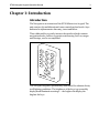
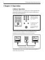
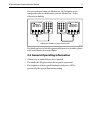
Distributed by
Any reference to Raytheon or
RTN in this manual should be
interpreted as Raymarine.
The names Raytheon and RTN
are owned by the
Raytheon Company.
ST80
Navigator
Keypad
Operation Manual
1
abc
4
jkl
7
rst
2
def
3
ghi
5
mn
6
opq
8
uvw
9
xyz
ins
0
del
nav
iga
tor
Navigator
ST80 Navigator Keypad Operation Manual
Package Contents
1. Navigator keypad
2. Thumb nuts (2)
3. Threaded fixing studs (2)
4. White sun cover
5. SeaTalk cable
6. Installation template
7. Operation manual
8. Warranty card
9. Operation cue card
10. Keypad installation guide
1
2
ST80 Navigator Keypad Operation Manual
Contents
Chapter 1: Introduction .............................................................. 3
Introduction ....................................................................... 3
Chapter 2: Operation ................................................................. 4
2.1 Basic Operation ............................................................ 4
2.2 General Operating Information ...................................... 5
Chapter 3: Problem Solving & Maintenance .............................. 6
3.1 Problem Solving ........................................................... 6
3.2 Maintenance ................................................................. 6
Chapter 4: EMC & Servicing Guidelines ..................................... 7
4.1 Important information ................................................... 7
4.2 Installation .................................................................... 7
4.3 Check Before Going to Sea ............................................ 8
4.4 Servicing and Safety ..................................................... 8
Chapter 5: Specification ............................................................ 9
3
ST80 Navigator Keypad Operation Manual
Chapter 1: Introduction
Introduction
The Navigator is an extension of the ST80 Masterview keypad. The
unit consists of a multidirectional cursor control pad and twelve keys
dedicated to alphanumeric data entry, insert and delete.
These dedicated keys greatly increase the speed at which common
navigational tasks, such as waypoint creation using Lat/Lon, ranges
and bearings, can be accomplished.
1
abc
4
jkl
7
rst
2
def
3
ghi
5
mn
6
opq
8
uvw
9
xyz
ins
0
del
nav
iga
tor
D1934-1
The Navigator keypad is permanently illuminated for ultimate clarity
in all lighting conditions. The brightness of the keys is governed by
display head illumination settings — the brighter the display the
brighter the keys.
4
ST80 Navigator Keypad Operation Manual
Chapter 2: Operation
2.1Basic Operation
The Navigator allows you to quickly enter or edit navigational data
displayed on a Masterview display head, using the alphanumeric,
insert, delete and trackpad keys.
1
abc
2
def
3
ghi
4
jkl
5
mn
6
opq
7
rst
8
uvw
9
xyz
ins
0
del
1
abc
2
def
3
ghi
4
jkl
5
mn
6
opq
7
rst
8
uvw
9
xyz
Use these keys to enter
alphanumeric data at the
current cursor position
(e.g. cycle of key 1 is 1,
a, b, c, 1 etc.)
0
ins
del
Use these keys to insert
or delete data at the
cursor position.
navigator
Use the multi-directional
trackpad keys to move
the cursor.
D2368-1
The Navigator can operate in one of two modes: unlinked or linked.
The factory default is unlinked. In this mode all Masterview
instruments respond to button presses on the Navigator.
masterview
SINGLE WP
020o23.82' N
052o04.02 E
1
abc
2
def
3
ghi
4
jkl
5
mn
6
opq
7
rst
8
uvw
9
xyz
ins
0
del
masterview
SINGLE WP
020o23.82' N
052o04.02 E
navigator
UNLINKED INSTRUMENTS & NAVIGATOR KEYPAD
D2369-1
This mode ensures that a newly installed units operate together as
soon as they are powered up.
5
ST80 Navigator Keypad Operation Manual
For users with more than one Masterview, the Navigator can be
configured so that it is dedicated to just one Masterview – this is
referred to as linking.
masterview
SINGLE WP
020o23.82 N
052o04.02 E
1
abc
2
def
3
ghi
4
jkl
5
mn
6
opq
7
rst
8
uvw
9
xyz
ins
0
del
navigator
1
abc
2
def
3
ghi
4
jkl
5
mn
6
opq
7
rst
8
uvw
9
xyz
ins
0
del
masterview
SINGLE WP
020o23.82 N
052o04.02 E
navigator
LINKED INSTRUMENTS & NAVIGATOR KEYPAD
D2370-1
For details on how to link Navigator and Masterview modules, please
refer to the Masterview setup chapter.
2.2 General Operating Information
• A short beep is emitted when a key is pressed.
• The small red LED glows when the keypad is operational.
• The brightness of the keypad illumination and power LED is
governed by the system illumination setting.
6
ST80 Navigator Keypad Operation Manual
Chapter 3: Problem Solving & Maintenance
3.1 Problem Solving
Keypad does not operate - power LED not illuminated
• Make sure the cable connecting the keypad to SeaTalk is connected
properly.
• Make sure the cable is not damaged. Replace the cable if it is
damaged.
Navigator operates all Masterview display heads
• Display heads and keypad are not linked. Please refer to the
Masterview manual for linking details.
Navigator does not operate Masterview display head
• Keypad has been previously linked to another Masterview. Enter link
mode to create a link between the keypad and display head.
3.2 Maintenance
• Periodically examine cables for signs of damage. Replace any
damaged cables.
• Always fit the protective sun cover when the keypad is not in use.
• If the keypad needs to be cleaned, use a moist lint-free cloth.
Chemical cleaning agents or abrasive compounds must not to
be used.
ST80 Navigator Keypad Operation Manual
7
Chapter 4: EMC & Servicing Guidelines
4.1 Important information
All Autohelm equipment and accessories are designed to the best
industry standards for use in the leisure marine environment.
Their design and manufacture conforms to the appropriate
Electromagnetic Compatibility (EMC) standards, but good
installation is required to ensure that performance is not
compromised. Although every effort has been taken to ensure that
they will perform under all conditions, it is important to understand
what factors could affect the operation of the product.
4.2 Installation
To avoid the risk of operating problems, all Autohelm equipment and
cables connected to it should be:
• At least 1m (3 feet) from any equipment transmitting or cables
carrying radio signals, e.g., VHF radios, cables and antennas. In the
case of SSB radios, the distance should be increased to 2m (7ft).
• More than 2m (6ft) from the path of a radar beam. A radar beam can
normally be assumed to spread 20 degrees above and below the
radiating element.
• The equipment should be supplied from a different battery than the
one used for engine start. Voltage drops below 10V in the power
supply to our products can cause the equipment to reset. This will not
damage the equipment, but will cause the loss of some information
and can change the operating mode.
• Genuine Autohelm cables should be used at all times. Cutting and
rejoining these cables can compromise EMC performance and so
should be avoided unless doing so is detailed in the installation
manual.
• If a suppression ferrite is attached to a cable, this ferrite should not be
removed. If the ferrite has to be removed during installation it must
be reassembled in the same position.
8
ST80 Navigator Keypad Operation Manual
4.3 Check Before Going to Sea
• Always check the installation before going to sea to make sure that it
is not affected by radio transmissions, engine starting etc..
• In some installations, it may not be possible to prevent the equipment
from being affected by external influences. In general this will not
damage the equipment but can lead to it resetting, or momentarily
may result in faulty operation.
4.4 Servicing and Safety
• Autohelm equipment should be serviced only by authorised
Autohelm service engineers. They will ensure that service
procedures and replacement parts used will not affect performance.
There are no user serviceable parts in any Autohelm product.
• Some products generate high voltages, and so never handle the
cables/connectors when power is being supplied to the equipment.
• Always report any EMC related problem to your nearest Autohelm
dealer. We will use any such information to improve our quality
standards.
9
ST80 Navigator Keypad Operation Manual
Chapter 5: Specification
Dimensions:
110 x 68 x 17mm (4.33 x 2.67 x
0.66in)
Power supply:
10 to 16V DC
Current consumption:
150mA illumination fully on
80mA at courtesy level
Operating temperature:
-10 to 70°C (14 to 158°F)
Buzzer:
Single tone beep
10
ST80 Navigator Keypad Operation Manual
81041-1
Navigator
Raytheon Marine Europe Ltd.
Anchorage Park, Portsmouth,
P03 5TD, England.
Telephone: (44) 1705 693611
Fax: (44) 1705 694642