1
JACKSHAFT
MOTOR-CONTROL
SYSTEM
FOR
RESIDENTIAL GARAGE DOORS
Model 815-RL
Installation Instructions
WARNING: To reduce the risk of injury to
persons, use this operator only with a
residential sectional door.
FOR INSTALLATION ONLY BY
QUALIFIED PERSONNEL
ZAP CONTROLS UK
100 Waterloo Boulevard
Anglesey Business Park
Cannock
Staffordshire WS12 1NR
United Kingdom
August 2006
IMPORTANT INSTALLATION
INSTRUCTIONS
WARNING:
To reduce the risk of Injury or death
READ AND FOLLOW ALL
INSTALLATION INSTRUCTIONS
Install only on a properly balanced door. An improperly balanced door has the potential to
inflict severe injury. Have a qualified service person make repairs to cables, spring assemblies,
and other hardware before installing the opener.
Remove all ropes and remove, or make inoperative, all locks connected to the garage door
before installing opener.
Where possible, install the door opener 7ft (2.1m) or more above the floor. Mount the emergency
Manual Over-Ride Lever 6ft (1.8m) above the floor.
Do not connect the opener to power until instructed to do so.
Locate the control unit:
(a): Within sight of the door,
(b): At a min height of 5ft so small children cannot reach it, and
(c): Away from all moving parts.
Install the entrapment label next to the control button in a prominent location using a suitable
secure mechanical means if necessary. Attach the emergency release marking on the emergency
release cable or next to the emergency release.
After installing the opener, the door must reverse when it contacts a 11/2” high object (or a 2” by
4” board laid on the floor).
The maximum door size should not exceed 160 square feet
(15 sq mtrs). The maximum door weight should not exceeed 500 pounds (230 Kgm).
FOR INTERNAL INSTALLATION ONLY
CONTENTS
Product Overview .............................................................................................. 1
Description ........................................................................................................ 2
Fitting the Super-Drive ....................................................................................... 3
Fitting the Manual Over-Ride lever .................................................................... 5
Fitting the Control unit ....................................................................................... 7
Fitting the Motor Cover kit ................................................................................. 8
Connecting the mains power supply .................................................................. 9
Testing the door operation ................................................................................. 11
Door speed change point and limit of travel calibration .................................... 12
Safety circuit and Photo-Eye wiring .................................................................... 14/15
Interlock circuit wiring ....................................................................................... 16
Accessory Radio Receiver wiring ....................................................................... 16
Programming ..................................................................................................... 16
Zap Transmitter code programming .................................................................... 17
Auto-Close timer programming .......................................................................... 18
Wiring diagrams ................................................................................................. 19
Fault Finding Guide ........................................................................................... 22
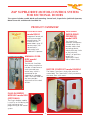
ZAP SUPER-DRIVE MOTOR-CONTROL SYSTEM
FOR SECTIONAL DOORS
The system includes model 800-R wall-mounting Control unit, Super-Drive jackshaft Operator,
Motor Cover kit and Manual Over-Ride kit.
PRODUCT OVERVIEW
CONTROL UNIT
model 800-R
JACKSHAFT
SUPER-DRIVE
OPERATOR
model 8472
Integrated Control unit
with case mounted
control button. This
Control unit will
power doors up to 15
square metres (160
square feet) in
conjunction with
model 8472 Operator.
The Super-Drive
Operator incorporates
a V-belt drive with a
Bowden cable v-belt
tensioning device,
which eliminates strain
on the jackshaft,
which is of particular
benefit for
applications fitted
with a hollow shaft.
MANUAL OVERRIDE model
ZA0093
The Manual Over-Ride
drive release mechanism
includes a Doorframe or
track mounted over
centre lever, which is
connected to the
Operator by a Bowden
cable. The screw hook on
the lever provides
adjustment of the v-belt
tension.
MOTOR COVER KIT model ZA0094
The Motor Cover front simply clips onto the
motor body. The Cover back is easily secured to
the cover front with screws.
PLUG-IN BEEPER
MODULE model 850
(OPTIONAL)
The Plug-in Beeper module
is useful as an aid during the
initial setting up and
programming of the control
system.
1
JACKSHAFT MOTOR-CONTROL SYSTEM
FOR
RESIDENTIAL GARAGE DOORS
Model 815-RL Installation Instructions
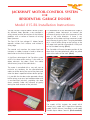
The Zap 815-RL low voltage DC Motor-Control
operates without limit switches and without a
safety edge.
It is preferable to set the overhead track angle at
a gradient above horizontal to increase the
influence of gravity on the initial movement of the
door in the close direction. If there is any
indication of the door resisting movement under
the influence of gravity then it may be preferable
to fit a set of buffer springs or leaf springs at the
fully open track position to provide an initial push
to start the door moving. (Pic 1)
The control unit monitors the motor load and
interprets a sudden increase in load as either an
obstruction or the limit of door travel.
The Controller will sense the open position of the
door when the counterbalance cables are pulled
tight at the radius of the track. (Pic 2)
The Zap Controls’ range of Motor-Control Systems
for Sectional Doors provides a new concept in
safety control and the elimination of the inherent
problems with a number of features of existing
door Operators.
A significant advantage of the Zap drive system
with its fast obstruction sensing, is that when an
object obstructs the doors travel, the cables
should never jump off the cable drums.
The motor is controlled with a very soft start to
minimise any tendency for the counterbalance
cables to slacken during the start of the close cycle
when the door is operated without buffer springs.
It is possible for the door to be operated without
buffer springs, even on a low headroom door with
a rear-mounted jackshaft, providing the door
closes smoothly under the influence of gravity
during the close rotation of the jackshaft.
Pic 2
The model 815-RL includes the model 800-R
Control Unit, model 8472 Super-Drive Operator,
model ZA0093 Manual Over-Ride kit and model
ZA0094 clip-on Motor Cover kit. (Pic 3 overleaf).
Pic 1
2
Pic 4
changes in door balance over a period of time.
However springs should be checked and adjusted
on each service visit at least once per year or 1500
door cycles, whichever is the sooner.
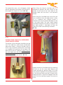
FITTING THE SUPER-DRIVE
OPERATOR
The Super-Drive Jackshaft Operator kit includes an
anti-torque arm, which prevents the operator
rotating and which is bolted to the Super-Drive
back plate using the motor cover back spacer
provided and secured to a spare hole on the
jackshaft bearing plate or onto the doorframe.
Pic 3
An optional Beeper model 850 may be fitted to
sound at the start of each door movement and
provide audible feedback during programming
and door position calibration.
It is preferable to lightly screw the torque arm to
the bearing plate hole or doorframe securing
point before mounting the Motor Cover and
Super-Drive. (Pic 5)
PREPARATION
Ensure that the door is free to move by hand
without any stiffness or misalignment of track
sections, which may cause the roller wheels to jump
over the track joints. If the door movement is stiff at
any point, the roller wheels should be adjusted to
allow the door to be moved by hand pressure
without any significant force. Any misalignment of
track sections should be corrected to ensure the
door runs smoothly.
Ensure that the door is reasonably well balanced
preferably with the counterbalance spring tension
biased slightly open. (Pic 4)
Pic 5
Counterbalance springs will weaken over time and
the balance can become biased closed. The Zap
obstruction sensing system automatically adjusts to
Now slide the Cover back onto the door shaft as
shown in the picture. (Pic 6 overleaf)
3
Align the Super-Drive keyway with the door shaft
keyway and fit the key supplied with the package.
Ensure that the two Allen screws are firmly tight
and then tighten the lock nuts. (Pic 8)
Pic 6
Next slide the Super-Drive assembly onto the door
shaft and select a suitable hole in the torque arm
to bolt it to the Super-Drive back plate using the
spacer bush, which should pass through the lower
slot in the Cover back. (Pic 7) The Cover back will
be secured later. The Torque Arm should be
approximately at right angles to the Super-Drive
assembly.
Pic 8
If there is no keyway one wall of a hollow door shaft
should be drilled with a 6mm or 1/4 -inch drill bit.
The main Allen screw in the boss of the Driven
pulley, should be replaced with the long Allen
screw, which is provided in the kit. The long screw
should be screwed into the drilled hole in the shaft
and tightened against the inside wall of the
opposite side of the shaft. The lock nut should then
be tightened to secure the screw. (Pic 9).
Pic 9
Pic 7
4
When fitting the Manual Over-Ride lever it is
preferable to position the lever relative to the
position of the end of the inner cable of the
Bowden cable with the lever in the horizontal
position.
The second Allen screw, set at 90 degrees, should
then be tightened and secured with the locknut.
Now tighten the torque arm screws (Pic 10)
When fitting the Over-Ride Lever ensure that the
lever is horizontal when the cable tension is taken
up. It is important that sufficient tension is
achieved to ensure that the drive belt does not slip
on the motor pulley. The lever should require
reasonable hand pressure to lock it into place. The
lever hook position is adjustable to allow the
Super-Drive V-Belt to be correctly tensioned.
(Pic 12)
Pic 10
FITTING THE MANUAL OVER-RIDE
LEVER MECHANISM
The position of the cable post should be assessed
next. The Cable Post, which secures the Bowden
cable outer sheath, is fixed to the door track or
frame using two M6 flat head screws and flange
nuts supplied. Drill two M6 or 1/4 inch holes in the
door track or frame in a position at least 25mm or
one inch higher than the fully extended position
of the outer cable, to allow movement of the
upper section of the outer sheath. (Pic 11)
Pic 12
Prepare the Manual Over-Ride lever by slackening
the lock nut on the screw hook adjuster and
unscrew the hook to a position where 75% of the
screw thread is exposed on the outside of the boss
nut. Slip the lever hook onto the D shackle whilst
holding the lever in a position 90 degrees from the
vertical with the lever base against the track or
frame.
Pic 11
5
Mark the hole positions for the Manual Over-Ride
lever on the door track or frame in a convenient
position with the lever held in the horizontal
position. Drill two M5 or 7/32nd of an inch size
holes. (Pic 13).
Pic 13
Fit the M5 screws provided with the screw head
on the inside of the track or doorframe. Fit the M5
nuts.
Pic 15
When the lever tension is correct push the lever
completely down to tension the V-Belt drive.
(Pic 16)
Secure the hook in the D-shackle of the over-ride
cable. (Pic 14)
Pic 14
Adjust the Over-Ride Lever hook position to
increase, or decrease tension by screwing it in or
out of its bush, see Pic 12. The hook should be
adjusted so that the lever is 90 degrees from the
vertical when the cable slack is taken up. (Pic 15)
Pic 16
6
FITTING THE CONTROL UNIT
The control unit lid can be temporarily secured to
the case side screw positions to prevent it hanging
by the cables during the setting up process.
(Pic 18)
Check that the control unit voltage, which is
shown on the label on the side of the control unit
case, is correct for the available single-phase
supply voltage.
The control unit model number has a suffix, which
relates to the supply voltage.
US is 120 volts
EU is 220 volts
UK is 240 volts
The US/120 volt control unit will operate on a 60
cycle single-phase supply. The EU/220 volt and
UK/240 volt control units will operate on a 50
cycle single-phase supply.
The control unit is mounted in a convenient
position near and within sight of the door and at
least 1.5 metres or 5 feet from the ground, with
screws provided passed through the mounting
holes in the corner pillars, which are outside of the
waterproof gasket. (Pic 17)
Pic 18
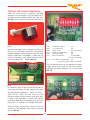
LOW VOLTAGE DC MOTOR WIRING
The Motor Cable is a three-core 3.8 metres (12.5
ft) long harness and is supplied factory fitted to the
three way terminal block of the 800-R controller at
the bottom right hand side of the circuit board,
which is marked “DC MOTOR”. (Pic 19)
Pic 17
Do not drill holes in the back of the case, as this is
liable to allow water ingress and cause damage to
the back of the printed circuit board.
Site the control unit so that any conduits are
routed to the BOTTOM of the case. DO NOT drill
the top or sides of the case as condensation within
the conduit will run down onto the panel and
cause operating problems and probable damage.
Pic 19
If the printed circuit board has to be removed from
its case, ensure that it is handled with care and not
placed on its back on any hard surfaces as this may
damage the ceramic surface mount components
on the rear of the printed circuit board.
The opposite end should be plugged into the
three-way terminal socket on the front plate of
the Super-Drive Operator. The motor cable should
7
be strapped to the Super-Drive Bowden cable with
cable ties to allow both cables to seat neatly in the
slot in the bottom of the Motor Cover. (Pic 20)
Pic 21
The upper two pegs in the top edge of the cover
back are next located in the two holes in the top
edge of the cover front. (Pic 22).
Pic 20
Do not cut or shorten the Motor Cable. Ensure
that any unused cable is coiled and secured away
from any moving parts, using the cable ties
provided.
NOTE THAT ALL TERMINALS ARE PLUG-IN FOR
EASE OF WIRING and that all terminal functions
are labelled on the panel.
FITTING THE MOTOR COVER KIT
Pic 22
The kit includes a front and back cover section.
The cover front has two clips, which clip over the
motor barrel.
Seat the cover back in the recess of the front
cover and fit the 2 bottom screws and at least
one of the side screws provided. (Pic 23 overleaf)
Position the cover front with the clips resting on
the motor barrel. Then firmly push the cover with
a hand over the cover clip positions to ensure that
the clips are seated in position over the motor
barrel. (Pic 21)
8
Pic 24
DO NOT PLUG THE POWER PLUG INTO THE
SOCKET YET. Please ensure that any unused
cable is coiled and secured using cable clips or
cable ties provided.
Pic 23
If the Control unit is to be wired permanently into
the house wiring circuit, then the main 120 volt
(Europe: 220 volt, UK 240 volt) supply lead, with
plug attached, should be removed from the
Control unit case as follows:
CONNECTING THE MAIN A/C
SUPPLY
The Operator should be installed in accordance
with local codes and national electric code.
1. Ensure that the main supply plug
disconnected from the line power supply.
To reduce the risk of electric shock, this equipment
has a grounding type plug that has a third
(grounding pin). This plug will only fit into a
grounding type outlet. If the plug does not fit into
the outlet, contact a qualified electrician to install the
proper outlet. Do not change the plug in any way.
is
2. Unscrew the outer clamp nut of the cable
gland through which the main supply cable
passes.
3. Unplug the GREEN power connector from the
panel socket.
If it is required to permanently wire the Control
unit to the permanent electric wiring in the
building then this should be completed by a
qualified electrician.
4. Unscrew the three supply wires from the
GREEN power connector.
5. Gently pull the cable through the loosened
cable gland.
The factory fitted Mains power cord should be
secured next. A 1.8 metres / 6 ft main power cable
is supplied ready connected to the 800-R
controller. It is plugged into the green 3-way
connector at the bottom left hand side of the
circuit board. (Pic 24)
6. Note that two sizes of cable gland entries are
provided in the Control unit case, both 3/4”
and 7/8”. Either entry may be used to provide
a conduit entry point for the new supply wiring.
Whichever entry point is not used should be
secured with a blanking plug of the correct size.
The power plug can then be located next to a
convenient power socket.
9
7. The new supply wiring should be terminated
to the GREEN connector block. The correct
locations for the Live, Neutral and Ground
wires are marked on the panel next to the
GREEN socket. The new Black (live) wire
should be terminated in the left hand terminal.
The White (neutral) wire should be terminated
in the center terminal and the Green (ground)
wire should be terminated in the right hand
terminal. (See Pic 24, previous page). Note
that alternative wire colors apply to UK and
Europe.
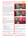
If the Lighting output is to be used then the
lighting wires should be routed by a qualified
electrician to the orange connector at the bottom
left hand side of the circuit board. A convenient
conduit outlet is provided in the bottom of the
case. The lighting circuit wiring should be rated at
3 Amps. (Pic 25)
Pic 26
DIP switch No.6 should be set to the OFF position
if the light is required to switch on when the door
is operated and turn off three minutes from the
last operation.
Switch No. 6 should be switched ON if the light is
required to switch ON when the door is opened
and switch OFF when the door is closed.
If a Remote operation Push Button is to be fitted
then it may be wired to operate in parallel with
the case mounted button, which is connected to
the CYCLE terminals on the printed circuit board.
(Pic 27)
Pic 25
The Lighting circuit may be wired to operate a
standard bulkhead light or floodlight of a
maximum rating of 250 watts.
If the Lighting output is to be used, then the
lighting MODE switch No. 6 should be set as
required. The 8-way DIP switch is located at the
top right hand side of the printed circuit board
panel. (Pic 26)
Pic 27
10
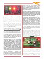
TESTING THE DOOR OPERATION
When the basic wiring is complete the door
operation may be tested. It may be helpful to fit
an optional Plug-in Beeper module (part No. 850)
(Pic 28), which sounds in conjunction with flashes
Pic 30
SW1
SW2
SW3
SW4
SW5
SW6
SW7
Pic 28
of the Acknowledge LED. The beeper will sound at
the start of each door movement and provides
audible feedback during programming and door
position calibration. The Beeper is fitted into the
white 3- way socket at the upper left hand side of
the panel market TB1 – Beeper (Pic 29).
SW8
SAFETY MODE
STANDARD SAFETY
12V PHOTO-EYE
AUTO-CLOSE
INTERLOCK OVER-RIDE
LIGHTING MODE
MOTOR POLARITY
OFF/N/C
OFF
OFF
OFF (NOT USED)
ON
OFF
AS REQUIRED
(See next paragraph)
STOP BUTTON OVER-RIDE ON
(A separate Stop button is not fitted).
Plug the power cord into the convenient power
supply socket and switch on the mains power.
Note that the power indicator LD3 is illuminated.
(Pic 31)
Pic 29
A momentary press of the case lid push button or
a remote push button, if fitted, operates the door.
The push button operation is: PRESS TO OPEN –
PRESS TO STOP – PRESS TO CLOSE – PRESS TO STOP.
The push button may be used to switch on a light,
if fitted, when the door is closed and without
moving the door, by an extended press of the push
button for 2 1/2 seconds until the light illuminates.
Pic 31
Note the factory set positions of each of the DIP
switches at the top right hand side of the panel
will be: (Pic 30)
11
DOOR DIRECTION ASSESMENT
The motor direction will depend on which side of
the shaft the Operator is mounted.
In order to assess the correct direction of
movement of the door first release the Manual
Over-Ride Lever and move the door manually to a
half open position. Then re-engage the Manual
Over-Ride Lever. Momentarily press the Control
unit case lid button. The door should initially run
in the OPEN direction and is confirmed by the
illumination of the OPENING LED at the top right
hand side of the control panel (pic 34). Now press
the case button to stop the motor. Then isolate
the main A/C power supply.
Pic 32
If the door runs in the closed direction, isolate the
main A/C power supply and set SW7, the Motor
Polarity switch to the opposite position. DO NOT
MOVE THE SWITCH WHILST THE MOTOR IS
RUNNING.
Pic 33
DOOR SPEED CHANGE POINT
CALIBRATION
Release the Manual Over-Ride Lever and move the
door manually to the fully closed position, reengage the lever and re-connect the mains power
supply. The microprocessor reference for the door
ground position should now be set. The procedure
is referred to as a CALIBRATION RESET. This is
completed as follows:
Pic 34
1. Press and hold the Reset button. (see pic 32
and 33).
2. Press and hold the Program button.
3. Release the Reset button.
4. Wait until the Acknowledge LED flashes (and
beeper sounds).
5. Then release the Program button.
6. The Acknowledge LED will flash twice (and the
Beeper will sound two beeps) to confirm.
compresses the buffer springs, if fitted, or reaches
the fully open position when the counterbalance
cables are pulled tight.
The microprocessor now knows the door opening
height and will calibrate the speed change points
after the next few runs, until they are set a few
seconds from each limit of door travel.
Now momentarily press the control unit push
button. Note that the opening LED is illuminated
whilst the door is opening. (pic 34)
Now momentarily press the case push button to
run the door in the close direction.
Note that the CLOSING LED, LD4, is illuminated
whilst the door is closing. (Pic 35 overleaf)
The door will run in fast speed for a few seconds
then change to slow speed and stop when it
12
a build up of snow and ice or other surface
material or subsidence of the ground surface. If
the fully closed position varies significantly over a
period of time it may be preferable to complete a
new CALIBRATION RESET.
If the door is subsequently moved by hand during a
power supply failure the speed change points will be
automatically re-established following confirmation
of the ground position after a complete door cycle
in both the open and close directions.
Pic 35
After the door has stopped in the fully closed
position, press the OPEN push button again. When
the door has stopped in the open position – press
the button to close the door. Complete another
door open and close cycle and confirm that when
the door has correctly calibrated the door stops
and remains stationary in the fully closed position.
If the door has been moved manually and is
operated in the close direction from a part open
position, it will stop and reopen from the fully
closed position. It will automatically synchronise
this calibration with reference to the ground
position during the following close cycle, which is
confirmed by periodic flashes of the Acknowledge
LED (or beeps of the beeper) during the close cycle.
After the door has calibrated, note that the
Acknowledge LED will momentarily flash (and the
optional beeper will sound) periodically whilst the
door is moving. (Pic 39 overleaf)
In essence the door will realign to the original
ground calibration reference by simply completing a
full open and close cycle.
The door fully closed position is registered after
running the door open and closed at least twice. A
1” (25.4mm) decision height is then maintained such
that if the door strikes an obstruction higher than 1”
(25.4mm) from the ground, it will stop and reopen.
If the roller wheels are too tight or if there is some
damage to the door track then the door may stop
before it reaches the limit position. If track
damage or stiffness is minimal then the motor
power may be increased to overcome the
restriction by adjusting the MAXIMUM POWER
preset control slightly clockwise. (Pic 36)
A satisfactory calibration sequence is confirmed if
the Acknowledge LED either does not flash or
flashes no more than three times after the door
has stopped in the closed position.
The Acknowledge LED may flash (and the beeper
sound) when the door stops in the fully closed
position. If it flashes (and beeps) it indicates that the
door fully closed position is higher than the original
calibrated ground position. Each flash (or beep)
represents 2 1/2 mm or 0.1”. For example two flashes
(or beeps) indicate that the door position is 5mm or
0.2” higher than the original calibrated ground
position. If it produces double flashes (and double
beeps) it indicates that the door fully closed position
is lower than the original calibrated ground position.
Pic 36
If the control is turned clockwise it will allow an
increase in current to flow to the motor and
consequently provide extra power to move the door.
This may occur due to a variation in the
compressibility of the weather strip on the bottom
of the door after a significant number of door
cycles from new, changes in ambient temperature,
The sensitivity of the door detecting and reacting
to an obstruction in fast speed in the CLOSE
13
direction may be adjusted with the CLOSE
SENSITIVITY preset. (Pic 37)
Pic 39
If either of the preset controls is adjusted, the
compression of the door edge seal will be affected
and thus the position of the fully closed door may
be different to the calibrated reference. In which
case it may be necessary to complete a new
Calibration Reset procedure.
Pic 37
If it is required to increase the obstruction
sensitivity, thus reducing the door edge pressure
required to activate the control unit obstruction
sensing circuit, which causes the door to stop and
re-open during the close fast speed cycle, then the
CLOSE SENSITIVITY adjuster should be turned
further clockwise. (Pic 38)
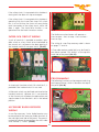
SAFETY CIRCUIT WIRING
If the door is to be operated without any
supplementary safety devices then the STANDARD
SAFETY SWITCH, DIP switch No. 2 and the 12 volt
Photo-Eye, DIP switch No. 3 should be set to the
OFF position.
If a safety device such as a Standard Photo-Beam
(Photo-Eye) or Safety Edge is to be fitted then the
STANDARD SAFETY switch, DIP Switch No. 2 should
be set to the ON position. This provides a Safety
STOP and RE-OPEN control of the door if the safety
circuit becomes active whilst the door is closing.
If a Photo-Eye with a Normally Closed relay circuit
is fitted, then the relay contact wires are
connected to the SAFETY terminals at the top
right hand side of the panel. (Pic 40)
Pic 38
Note that this will also increase the possibility of the
controller reacting to slight abnormalities or minor
damage to the track or misalignment of track
sections. This may cause fluctuations in the motor
current and may be significant enough to result in
the door stopping and re-opening. It is therefore
important that the smooth movement of the door
is tested by releasing the manual over-ride lever and
moving the door by hand in both directions.
Both preset controls are factory set to the 12
o-clock positions. Providing the door runs
smoothly by hand in both directions it is unlikely
that the presets will require adjustment.
Pic 40
14
12 VOLT TWO WIRE PHOTO-EYE
WIRING
See the wiring diagrams on pages 19 and 20.
If two or more Photo-Eyes, or any other safety
devices are fitted then each switching circuit
should be wired in series.
A 12 volt two wire Photo-Eye may be wired to the
terminals marked at the top of the panel. (Pic 43).
DIP switch No. 3 should be set to the ON position.
Wiring diagrams for various types of photo-eye
units are shown on pages 19 and 20.
A 24-volt Photo-Eye or other accessory may be
powered from the 24-volt DC accessory Radio
supply terminals at the lower right hand side of
the panel. The 24-volt accessory supply may be
used to power other accessories such as an
accessory radio receiver (non Zap). (Pic 41) The
maximum current should not exceed 200mA.
Pic 43
Each time the Safety circuit is activated LED LD2
the SAFETY ACTIVE indicator will illuminate. This
is useful when testing the operation of the photoeye or other safety device without running the
door. (Pic 44)
Pic 41
An Over-Load circuit will trip if the accessory load
current exceeds 200mA. This is indicated by the
illumination of the OVER-LOAD LED. If the overload does trip then isolate the main power for at
least 20 seconds to allow the over-load circuit to
reset and disconnect the excessive load.
The range of Zap Photo-Eye units has been
designed for universal supply operation. They can
be powered from 12 to 240 volts DC or 24 to 240
volts A/C. (Pic 42)
Pic 44
In Europe it is necessary to arrange for a standard
safety circuit to be monitored for both an open
circuit and a short circuit in which case the circuit
must include an 8.2 K resistor at the furthest point
in the external circuit. DIP Switch No. 1 should be set
to ON which is the position marked RES for resistive.
When the circuit is to be operated as Normally
Closed then DIP switch No. 1 should be set to OFF.
This position is marked N/C on the panel for
Normally Closed.
Pic 42
15
If the safety circuit is interrupted whist the door is
closing then the door will stop and reopen.
If the safety circuit is interrupted whist the door is
operating with the Auto-Close timer DIP switch
No. 4 set to ON then the timer will reset during
each interruption of the safety circuit, whilst the
door is open. The Auto-Close function is not
operational for the North American market.
Pic 46
The Radio transmitter button will operate as:
Press to open – Press to stop – Press to close –
Press to stop.
INTERLOCK CIRCUIT WIRING
A pair of terminals is provided to enable a pass
door switch or a key switch to be interlocked to
the control unit, to prevent the door opening if
the interlock terminals are open circuit. (Pic 45).
The wiring of a non-Zap accessory radio is shown
on pages 17 and 18.
A Zap radio receiver model 840 may be fitted in
the socket marked “ZAP RADIO” at the top lefthand side of the panel. (Pic 47)
Pic 47
PROGRAMMING
The following functions can be programmed using
the Program Button, which is located at the top of
the panel. (Pic 48)
Pic 45
An Inter-Lock Over-ride switch, DIP switch No. 5, is
provided if the interlock circuit is not used.
A Slide Lock switch may be fitted and wired to the
interlock terminals. However this is not essential
as the Control unit will detect the obstruction and
stop the door if the slide lock is left in the locked
position.
ACCESSORY RADIO RECEIVER
WIRING
A non-Zap accessory 3-wire Radio Receiver may
be connected to the accessory Radio terminals at
the mid right hand side of the panel. The panel is
marked to indicate the connections for the 3 radio
wires marked 1, 2 and 3. (Pic 46)
Pic 48
16
An optional alternative programming sequence,
using the case lid button, is provided for programming additional transmitters as follows:
When the program button is pressed and held, a
sequence of flashes of the Acknowledge LED follows
at 4-second intervals. If a Bleeper is fitted then the
Bleeper will sound with the flashes of the LED.
1. Close the door.
2. Press and hold the new transmitter button.
3. Press and hold the case lid button for at least
2.5 seconds. This will operate the lighting relay
without opening the door. A click of the relay
will be heard if no light is wired to the control
unit. If a Beeper is fitted the beeper will beep
when the button is pressed and give a second
beep after 2 seconds. Now release the case lid
button.
4. The new transmitter code will be read into
memory and the lighting relay will operate to
flash the light if fitted. Otherwise the relay
clicks can be heard. If a beeper is fitted then
two beeps will confirm that the new
transmitter code has been stored into memory.
5. Release the transmitter button.
6. Now operate the new transmitter within 5
seconds to open the door.
7. If the new transmitter has not been used within
5 seconds it’s code will be automatically erased.
The first flash or bleep indicates the Zap remote
control transmitter program mode.
The second flash or bleep indicates the AutoClose timer program mode. (This function is not
available for the North American market)
The third flash or bleep indicates the Close Delay
program mode, which allows an optional Warning
device to operate before the door starts to close.
The fourth flash or bleep indicates the Zap
transmitter code memory erasure mode.
The program button should be released after the
appropriate flash or bleep to enter the required
program mode.
All of the programmed functions are stored in a
non-volatile memory, which is retained during a
power interruption.
Up to 10 transmitter codes can be stored in
memory. In which case repeat the programming
sequence for each of the new transmitters. (Each
transmitter has a different operating code)
TRANSMITTER CODE PROGRAMMING
Programming of a new transmitter to a non-Zap
accessory radio receiver will be covered in the
instructions supplied by the manufacturer of the
receiver.
To erase all transmitter codes: Press and hold the
Program button and release it after the FOURTH
flash or beep.
A Zap radio receiver model 840 may be fitted in
the socket marked “ZAP RADIO” at the top left
hand side of the panel. (Pic 47 page 15)
To program a Zap transmitter code into memory:
Two flashes or beeps acknowledge that all of the
transmitter codes have been erased.
1. First press and hold the required transmitter
button.
REMOTE CONTROL OF THE LIGHT
When the Light Mode DIP switch No. 6 is set to OFF
(3 minute light timer) a remote control transmitter
may be used to turn on the light without opening
the door by pressing and holding the transmitter
button for at least 2 seconds until the light
illuminates. The door should not move providing the
transmitter signal has been continuous.
2. Then press and hold the Program button.
3. Release the program button after the first LED
flash or bleep.
4. Two flashes or bleeps confirm that the code
has been stored into memory.
5. Now release the transmitter button.
Momentary operation of the transmitter for up to
one second will cause the door to move and the
light to illuminate.
Three flashes or beeps indicate that no code data
was present, in which case repeat the programming
sequence.
17
AUTO-CLOSE TIMER
PROGRAMMING
Auto-Close regardless of the door re-opening
after striking an obstruction.
This function is not available for the North American
market.
It is preferable that the door should re-open and
stay open following an obstruction strike.
However it may be required for security reasons
that the door should Auto-Close after re-opening,
after hitting a large build-up of snow and ice in
winter, in which case it will make two attempts to
close onto the ice. If the snow and ice has not
compressed then on the third run it will then stop
on the ice.
The factory set Auto-Close timer delay is 15 seconds.
In order to confirm the operation of the AutoClose timer first set DIP switch No. 4 to ON. Then
press the case push button to open the door. The
door will open and re-close after the time delay.
The factory preset time delay is 15 seconds.
If the door is required to Auto-Close regardless of
such an obstruction then press the close button a
second time during the 6 flashes and bleeps.
To change the Auto-Close time delay proceed as
follows:
1. Close the door.
If the CLOSE button is not pressed during the
flashes and beeps the controller will default to
stay open after an obstruction re-open sequence.
2. Set DIP switch No. 4 to the ON position.
3. Press and hold the program button.
4. Release the button after the SECOND flash or
beep.
If it is required to change the programmed delay
then repeat the programming sequence.
5. Press the OPEN push button.
If a Zap Radio Remote Control system is fitted and
the Auto-Close function is enabled then operation
of the transmitter will only open the door. The
door will close after the programmed time delay.
6. After the door has fully opened and after the
required delay press the CLOSE push button.
This new delay will now be stored into the
memory and retained during any power
interruptions.
Whilst the door is open, the close delay is reset
each time the Zap transmitter is operated and
each time a safety circuit or Photo-Eye is activated.
A sequence of 6 flashes and beeps follow to
prompt you to decide if you want the door to
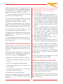
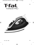
ZAP 800-R CONTROLLER WIRING
ACCESSORY RADIO – PULSE OPERATION
8
18
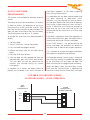
ZAP 800-R CONTROLLER WIRING –
PULSE OPERATION WITH LIFT MASTER 412 HM RADIO
"
;
!
2 75( 6+( $6( (&(,8(4 9,6+ 6+(
" 21642//(4 :27 0756
&+$1*(
6+(
(&(,8(4
)420
20(16$4: 23(4$6,21 62 2156$16
23(4$6,21 +( -703(4 /,1.,1* 2)
6+( 76376 '74$6,21 6(40,1$/5
5+27/' %( 64$15)(44(' 62 6+( 6(40,1$/5 1($4(56 6+( 276(4 ('*( 2)
6+( 3$1(/ 9+,&+ $4( 0$4.(' <= )24
23(4$6,21
1*$563&
,) 6+( $',2 (&(,8(4 '2(5 126
23(4$6(3423(4/:6+(159,6&+6+(
&211(&6,215216(40,1$/
244()(462
6+(4(&(,8(40$17$/)24)746+(4
',4(&6,215 21 &211(&6,215 62 $ 329(45733/:
19
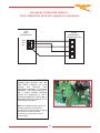
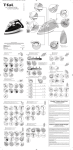
ZAP 800-R – SAFETY WIRING CONNECTIONS – ZAP PHOTO-EYES
!
!
!
!
20
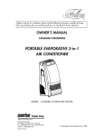
ZAP 800-R – SAFETY WIRING CONNECTIONS – NON-ZAP PHOTO EYES
! ! ! """"""""""""""""""""""""""""" """""""""""""""""""""""""""""""""
21
FAULT FINDING GUIDE
FAULT
REASON & REMEDY
1. The door stops just
after it has started in
the open direction.
A. The door movement is stiff due to the door running tight against
the door frame in the fully closed position. In which case adjust the
position of the roller wheel supports to ease the pressure of the
door against the frame.
B. The door is badly out of balance. In which case re-tension the
counterbalance springs.
C. The door is near the maximum weight for the operator and the
Maximum Motor Current adjuster is set too low. In which case turn
the adjuster a further 20 degrees counter-clockwise.
2. The closing door
stops and reopens
before it contacts the
ground.
A. There is an abnormality in the track, which is causing the roller
wheels to jump. This may be due to a misalignment of track
sections or a deformity of a damaged section of track. In which
case correct the track problem and ensure the door will run
smoothly by hand movement with the over-ride lever disengaged.
B. The Close Sensitivity adjuster is set too fine. In which case turn the
adjuster counter-clockwise by a further 20 degrees.
22
ZAP CONTROLS UK
100 Waterloo Boulevard
Anglesey Business Park
Cannock
Staffordshire WS12 1NR
United Kingdom