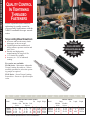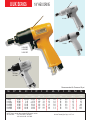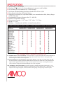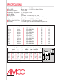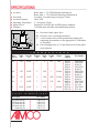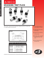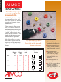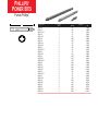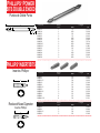
1
ZAPRASZAMY NA : www.techsystem.pl tel./fax: +48 33 816 73 62 tel: +48 33 816 73 61 ELECTRONIC TOOL CATALOG A I M C O SCREWDRIVERS Mechanical Torque Screwdrivers Electric Screwdrivers Pneumatic Screwdrivers Pulse Screwdrivers Battery Screwdrivers 6 8 11 15 19 MECHANICAL TORQUE SCREWDRIVERS QUALITY CONTROL IN TIGHTENING THREADED FASTENERS Ensure repeatable and consistent tightening for quality control in your assembly applications with the AIMCO mechanical torque wrench series. Torque Limiting Manual Screwdrivers ● ● ● ● ● Accurate and smooth rotary clutch disengages at the set torque. Lightweight and streamlined tool design ensures operator comfort and ease of use. Durable and high quality manufacturing for long tool life. 1/4” female hex spindles Accuracy is ± 3% of indicated reading. o ADDITIONAL ENGLISH AND METRIC MODELS NOW AVAILABLE FOR ALL WRENCH STYLES. Two series are available: TLSM Series - Micrometer Adjustable Torque Limiting Screwdriver - Allows assembly personnel to select the operating torque as required. TLSP Series - Preset Torque Limiting Screwdriver - Preset to a specific torque value. S P E C I F I C A T MICROMETER ADJUSTABLE SERIES Model Range Dir. Min-Max Grad. Min-Max Grad. In.Lbs. Kgf.cm* TLSM-6 1 - 6 .025 TLSM-12 2 - 12 .05 TLSM-26 6 - 26 .1 TLSM-50 10 - 40 .25 1-6 2 - 12 6 - 26 10 - 50 .05 .1 .2 .25 Length Weight CW 3-7/8” 3.5 Oz CW 4-9/16” 5.5 Oz CW 5-1/2” 9.5 Oz CW 6-1/8” 13 Oz *For Metric MicroMeter Adjustable Series add “A” at the end of Model Number I O N S Weight PRESET SERIES Model Range Min-Max Min-Max In.Lbs. Kgf.cm Dir. Length TLSP-12 TLSP-26 TLSP-50 4 - 10 10 - 22 20 - 40 CW CW CW 3-11/16” 3.25 Oz 4” 5.25 Oz 4-3/4” 10.5 Oz 4 - 12 10 - 26 20 - 50 Click Wrench - Torque Indicating Ratchet Wrench Series ● ● ● ● ● ● S Model CWR-100 CWR-200 CWR-75F CWR-250F P E Min-Max Torque indicating tools provide a very repeatable and detectable action. Micrometer adjustable. Lightweight and streamlined tool design ensures operator comfort and ease of use. Overall length of the wrench is designed so the operator can comfortably apply torque without undue strain. 1/4” through 1/2” square drive sizes fit standard sockets Accuracy is ± 3% of indicated reading. C Grad. I Range F Min-Max I C Grad. 40 - 100 In Lbs 2 In Lbs 40 - 120 Kgf.cm* 2.3 Kgf.cm 50 - 200 In Lbs 2.5 In Lbs 50 - 225 Kgf.cm* 2.9 Kgf.cm 15 - 75 Ft Lbs 1 Ft Lbs 200 - 900 Kgf.cm* 10 Kgf.cm 30 - 250 Ft Lbs 2 Ft Lbs 4 - 28 Kgf.m* 0.2 Kgf.m *For Metric Series add “A” at the end of Model Number A T I Direction Hand Force CW CW CW CW 18.75 Lbs Max 30 Lbs Max 85.75 Lbs Max 131.5 Lbs Max O N Sq. Drive Length 1/4” 1/4” 3/8” 1/2” 7.125” 8.375” 12.75” 38.5” S Weight .125 Lbs .5 Lbs 1.5 Lbs 7.1 Lbs ELECTRIC SCREWDRIVERS ELECTRA SERIES ● ● ● ● Ergonomic Design Excellent Torque Control Long Tool Life External Brush Replacement ● ● ● ● External Torque Adjustment UL Listed Direct Plug-In Style State of the Art Motor Design AE-1511HS AE-7000 AE-8000 AE-2000 AE-4500 AE-1411 AE-2411 Pistol Grip Handle Attachment AE-7000A S P E PUSH-TO-START DIRECT PLUG-IN Model C I F Fastening Torque (approx.) kgf-cm in-lbs AE-1411 AE-2411 AE-1511HS 3~16.1 6.9~29.9 4~17.3 2.6~14 6.0~23.4 3.5~15 I C Free Speed (approx.) rpm 1,000 1,000 1,900 A T I Weight (approx.) lb kg Length (approx.) mm in 1.6 1.6 1.6 273 273 273 O N S Bit-Shank Power Source 10.7 10.7 10.7 1/4” HEX 1/4” HEX 1/4” HEX AC 110/120V* 60Hz Weight (approx.) lb kg Length (approx.) mm in Bit-Shank Independent Power Supply 0.7 0.7 1.4 1.4 204 204 237 237 0 2mm 1 110-220 VAC 110-220 VAC 110-220 VAC 110-220 VAC .72 .72 .72 * 220V available upon request. Fastening Torque (approx.) kgf-cm in-lbs AE-2000 AE-4500 AE-7000 AE-8000 1 .4~1.5 1.5~9.4 7~20.1 12~30 720 720 750 550 .31 .31 .64 .64 8.0 8.0 9.3 9.3 1/4” HEX 1/4” HEX 1/4” HEX 1/4” bit adapter available. Order part no. AE-2000BA Model Fastening Torque (approx.) kgf-cm in-lbs AE-7000A AE-8000A 7.5~20.7 12.7~32.3 TORQUE ADJUSTER COVER ANGLE .35~1.3 1.3~8.2 6.1~17.4 10.4~26 Free Speed (approx.) rpm 6.5~18 11~28 Free Speed (approx.) rpm 550 400 Weight (approx.) lb kg Length (approx.) mm in Bit-Shank Angle Height mm in 2.0 2.0 325 325 1/4” HEX 1/4” HEX 35 35 Model Part Number AE-1411/ 1511HS/ 2411 AE-2000/ 4500 AE-7000/ 8000 AE-TC1424 AE-TC2045 AE-TC7080 .91 .91 PISTOL GRIP ADAPTERS LEVER START Model 12.8 12.8 1 3/8 1 3/8 Model Part Number AE-1411/ 1511HS/ 2411 AE-7000/ 8000 AE-PG1424 AE-PG7080 ELECTRA DC BRUSHLESS SERIES ● Approved for Clean Room Environment - Can be used in Clean Room to Class 100. ● High Reliability and Long Tool Life - Use of brushless electric motor and non-mechanical switch insures reliable long life and low maintenance. ● Adjustable RPM Selection Allows you to choose which RPM is best suited for proper fastening speed and operator control. ● Soft Start Selection - Allows the choice of engaging fastener at an initial RPM for early thread engagement. CE-350 CR-1000 CR-1100 CR-1200 CR-PS CONTROLLER S Model P E C I Fastening Torque (approx.) kgf-cm in-lbs F I C A Free Speed (no load) (approx.) rpm lb T Weight (aaprox.) I O N S Bit-Shank kg Length (approx.) mm in 0 2.5MM*** CE-350* .86~4.0 .75~3.5 730 0.4 .20 160 6.3 CR-1000 CR-1100 CR-1200 2.5~7.5 4~17 7~27 2.2~6.7 3.4~14.7 6.1~23.4 300~1,000** 600~2,100** 300~1,000** 1.4 1.4 1.4 .64 .64 .64 267 267 267 10.5 10.5 10.5 1/4” HEX 1/4” HEX 1/4” HEX *CE-350 contains sealed brush-type motor. Not certified for Class 100 use. **R.P.M. selection dial and soft start selection switch on Power Supply Unit ***1/4” bit adapter option available. Order no. AE-350BA Model AE-PSL* CR-PS Power Source AC 110/120V, 60Hz AC 110/120V, 60Hz Dimensions Weight (approx.) Available for Driver Models (W x H x D) (in) lb kg 3 x 4-1/4 x 6-1/4 3-3/4 x 2 x 7-3/4 6.2 1.6 2.8 0.7 *AE-PSL does not come standard with the tool. Must be ordered separately. CE-350 CR-Models AIM/ELECTRA SLIP CLUTCH ELECTRIC SCREWDRIVER AIMCO’s Electra Series Model AE-2015 electric screwdriver offers high-speed performance for quick and consistent assembly and dissassembly. To maximize ergonomics and convenience, this driver offers a combination of a slip clutch with a high speed motor to provide low torque reaction and the best power-to-weight ratio in the industry. To insure tool reliability, an LED light notifies the operator when to change brushes. And as a safety feature, the brush cap contains a switch which shuts off the power during brush replacement. ■ Direct 110V or 220V Plug-In Eliminates the need for a bulky external power supply. ■ 1/4” Hex Quick Change Chuck Allows easy bit replacement. ■ External Torque Collar - Allows easy torque adjustment. S P E C I F I C A T I O N S Model Torque Range in-lbs Kgf-cm RPM Length in. Weight lbs. Diameter in. Power Source AE-2015 2.0 - 15.0 2.3 - 18.0 1,000 9.2 1.2 1.35 115VAC 50/60Hz AE-2015V 2.0 - 15.0 2.3 - 18.0 1,000 9.2 1.2 1.35 220VAC 50/60Hz PNEUMATIC SCREWDRIVERS TORQUE CONTROL “LITE TOUCH” SERIES INLINE PUSH-TO-START TYPE US-LT10B US-LT20B US-LT40B ERGONOMIC NEOPRENE GRIPS STANDARD WITH MODELS LT10B LT40B SERIES US-LT50B US-LT30B-11 Recommended Air Pressure: 85 psi S P Model E C I F I C Torque Range Free Speed Overall Length (approx.) (Soft Joint) (approx.) (approx.) Nm in-lbs rpm mm in A T I O Weight From Center to Outside (approx.) (approx.) lb kg mm in N S Noise Average Air Level Consumption dB(A) ft3/min US-LT10B 0.20~0.59 1.7~5.2 1,000 191 7.5 0.6 0.3 12 0.5 70 5.2 US-LT20B-10 US-LT20B-18 US-LT20B-26 0.15~1.08 0.15~0.67 0.15~0.34 1.3~9.5 1.3~6.1 1.3~3.0 1,000 1,800 2,600 180 180 180 7.1 7.1 7.1 0.7 0.7 0.7 0.3 0.3 0.3 13 13 13 0.5 0.5 0.5 71 71 71 5.6 5.6 5.6 US-LT30B-11 US-LT30B-17 US-LT30B-23 0.39~1.96 0.39~1.47 0.39~0.98 3.5~17.4 3.5~13.0 3.5~8.7 1,100 1,700 2,300 183 183 183 7.2 7.2 7.2 0.9 0.9 0.9 0.4 0.4 0.4 16 16 16 0.6 0.6 0.6 73 73 73 7.0 7.0 7.0 US-LT40B-08 US-LT40B-15 US-LT40B-21 0.98~3.92 0.98~2.17 0.98~1.67 8.7~34.7 8.7~19.1 8.7~14.8 800 1,500 2,100 205 205 205 8.1 8.1 8.1 1.4 1.4 1.4 0.6 0.6 0.6 17 17 17 0.6 0.6 0.6 74 74 74 10.5 10.5 10.5 US-LT50B-05 US-LT50B-08 US-LT50B-17 1.47~10.30 13.0~91.1 1.47~5.40 13.0~47.7 1.47~2.80 13.0~25.1 480 800 1,700 240 240 240 9.4 9.4 9.4 2.2 2.2 2.2 1.0 1.0 1.0 20 20 20 0.8 0.8 0.8 75 75 75 17.5 17.5 17.5 Each model is equipped with its standard clutch spring. Additional clutch springs specifications are available to provide a full torque range of each model on page 38. Air Hose Size: 1/4” for US-LT10B - US-LT40B Series 3/8” for US-LT50B Series Air Inlet Thread (Pipe Tap): 1/8” for US-LT10B - US-LT20B Series 1/4” for US-LT30B - US-LT50B Series TORQUE CONTROL “LITE TOUCH” SERIES PISTOL TYPE US-LT31PB-05 US-LT41PB SERIES US-LT31PB SERIES US-LT51PB SERIES US-LT60P SERIES US-LT60P(P) SERIES Torque Reaction Bar Standard with US-LT60P Series Recommended Air Pressure: 85 psi S P Model E C I Torque Range (approx.) (Soft Joint) Nm in-lbs F I C Free Speed Overall Length (approx.) (approx.) rpm mm in A T I O Weight From Center to Outside (approx.) (approx.) lb kg mm in N S Noise Average Air Level Consumption dB(A) ft3/min US-LT31PB-05 US-LT31PB-11 US-LT31PB-17 US-LT31PB-23 0.98~5.59 0.3 ~1.96 0.39~1.47 0.39~0.98 8.7~49.6 3.5~17.4 3.5~13.0 3.5~8.7 500 1,100 1,700 2,300 200 170 170 170 7.9 6.7 6.7 6.7 1.9 1.6 1.6 1.6 0.8 0.7 0.7 0.7 16.0 15.5 15.5 15.5 0.6 0.6 0.6 0.6 73 73 73 73 7.0 7.0 7.0 7.0 US-LT41PB-08 US-LT41PB-15 US-LT41PB-21 0.98~3.92 0.98~2.17 0.9 ~1.67 8.7~34.7 8.7~19.1 8.7~14.8 800 1,500 2,100 185 185 185 7.2 7.2 7.2 1.8 1.8 1.8 0.8 0.8 0.8 16.5 16.5 16.5 0.6 0.6 0.6 74 74 74 10.5 10.5 10.5 US-LT51PB-05 US-LT51PB-08 US-LT51PB-17 1.47~10.30 13.0~91.1 1.47~5.40 13.0~47.7 1.47~2.80 13.0~25.1 480 800 1,700 205 205 205 8.5 8.5 8.5 2.6 2.6 2.6 1.2 1.2 1.2 19.5 19.5 19.5 0.7 0.7 0.7 75 75 75 17.5 17.5 17.5 US-LT60P-03(P) US-LT60P-07(P) US-LT60P-11(P) 6.80~16.66 60.0 ~147.6 3.92~9.80 34.7~86.8 2.94~5.88 26.0~52.1 320 650 1,100 240 230 230 9.4 9.0 9.0 3.7 3.7 3.7 1.7 1.7 1.7 22.0 22.0 22.0 0.9 0.9 0.9 75 75 75 21.0 21.0 21.0 Each model is equipped with its standard clutch spring. Additional clutch springs specifications are available on page 38 (P) DENOTES 3/8” SQ. DRIVE FOR US-LT60P SERIES. Air Hose Size: 1/4” for US-LT31PB & US-LT41PB Series 3/8” for US-LT31PB-05, US-LT51PB Series & US-LT60P Series Air Inlet Thread (Pipe Tap) : N.P.T. 1/4” TORQUE CONTROL “LITE TOUCH” SERIES ANGLE AND LEVER TYPE US-LT30BL-11 US-LT30BL-17 US-LT30BL-23 US-LT40BL-08 US-LT40BL-15 US-LT40BL-21 US-LT40-03C US-LT40B-05C/08C/15C US-LT30B-11C Recommended Air Pressure: 85 psi S P Model E C I Torque Range (approx.) (Soft Joint) Nm in-lbs F I C Free Speed Overall Length (approx.) (approx.) rpm mm in A T I O N S Weight From Center to Hex Bit or Noise Average Air (approx.) Outside (approx.) Drive Size Level Consumption lb kg mm in in dB(A) ft3/min 3.5~24.3 3.5~17.4 20.0~49.5 8.7~33.8 8.7~18.2 1,100 1,700 500 800 1,500 273 273 322 320 320 10.7 10.7 13.0 12.8 12.8 1.5 1.5 2.1 2.0 2.0 0.7 0.7 0.9 0.9 0.9 10 10 13 10 10 0.4 0.4 0.5 0.4 0.4 1/4” 1/4” 1/4” 1/4” 1/4” 73 73 84 74 74 7.0 7.0 12.4 10.5 10.5 US-LT40-08C US-LT40-15C US-LT40-05C US-LT40-03C 0.98~3.82 0.98~2.06 2.26~5.60 4.90~9.80 8.7~33.8 8.7~18.2 20.0~49.5 43.4~86.8 800 1,500 550 315 320 320 322 360 12.8 12.8 13.0 14.2 2.0 2.0 2.1 2.4 0.9 0.9 0.9 1.1 10 10 13 13 0.4 0.4 0.5 0.5 1/4” Sq. 1/4” Sq. 1/4” Sq. 1/4” Sq. 74 74 84 74 10.5 10.5 12.4 12.4 US-LT30BL-11 US-LT30BL-17 US-LT30BL-23 0.39~1.96 0.39~1.47 0.39~0.98 3.5~17.4 3.5~13.0 3.5~ 8.7 1,100 1,700 2,300 209 209 209 8.2 8.2 8.2 1.2 1.2 1.2 0.5 0.5 0.5 15 15 15 0.6 0.6 0.6 1/4” 1/4” 1/4” 73 73 73 7.0 7.0 7.0 US-LT40BL-08 US-LT40BL-15 US-LT40BL-21 0.98~3.92 0.98~2.17 0.98~1.67 8.7~34.7 8.7~19.1 8.7~14.8 800 1,500 2,100 231 231 231 9.1 9.1 9.1 1.5 1.5 1.5 0.7 0.7 0.7 17 17 17 0.7 0.7 0.7 1/4” 1/4” 1/4” 74 74 74 10.5 10.5 10.5 Each model is equipped with its standard clutch spring. Additional clutch springs specifications are available on page 38 Angle Head Height: 36mm Air Hose Size: 1/4” for all models Air Inlet Thread (Pipe Tap): N.P.T. 1/4 LEVER 0.39~2.74 0.39~196 2.26~5.60 0.98~3.82 0.98~2.06 ANGLE US-LT30B-11C US-LT30B-17C US-LT40B-05C US-LT40B-08C US-LT40B-15C US-LT SERIES S P E Model OPTIONAL CLUTCH SPRINGS C I F I C Clutch Springs Provided Standard Option US-LT10/10B US-LT20B-10 Black Black Red Yellow US-LT20B-18 Red US-LT20B-26 US-LT31PB-05 Yellow Red US-LT30 Series, 1100 rpm Blue Yellow Pink US-LT30 Series, 1700 rpm Black Red US-LT30 Series, 2300 rpm US-LT40-03C US-LT40 Series, 800 rpm Pink Red Black Red Pink (not included) Pink Red Yellow US-LT40 Series, 1500 rpm Red US-LT40 Series, 2100 rpm US-LT50 Series, 500 rpm Yellow Black Yellow Red Yellow US-LT50 Series, 800 rpm Red US-LT50 Series, 1700 rpm Yellow Yellow EXTERNAL TORQUE ADJUSTMENT (Air Shut-off) Set the hand driver through the slot into the key hole on the Adjusting Gear and turn clockwise to increase torque and counter clockwise to decrease. SILENCER ASSEMBLIES Tool Direct Type Leader Hose Exhaust Hose Model Silencer Assembly Assembly US-LT10 SERIES US-LT20 SERIES US-LT30 SERIES US-LT40 SERIES N/A 455-088-2 408-088-2 496-088-1 934-201-0 934-201-0 934-150-0 934-150-0 459-885-1 455-885-1 408-885-0 496-885-1 A T I O N Torque Range Hard Joint Nm in/lbs 0.20~0.59 0.34~1.08 0.20~0.67 0.15~0.34 0.24~0.67 0.15~0.34 0.15~0.34 2.35~5.59 0.98~2.74 0.98~1.96 0.67~1.76 0.39~0.98 1.22~2.74 0.67~1.47 0.39~0.98 0.39~0.98 4.90~9.80 1.57~3.92 0.98~2.17 0.98~1.67 0.98~2.17 0.98~1.67 0.98~1.67 4.9~10.3 2.9~5.4 1.4~2.5 2.7~5.4 1.4~2.5 1.4~2.8 S Clutch Spring Code Number 1.7~5.2 3.0~9.5 1.7~6.1 1.3~3.0 2.2~6.1 1.3~3.0 1.3~3.0 20.9~49.6 8.7~24.3 8.7~17.4 6.1~15.6 3.5~8.7 10.8~24.3 6.1~13.0 3.5~8.7 3.5~8.7 43.4~86.8 13.9~34.7 8.7~19.1 8.7~14.8 8.7~19.1 8.7~14.8 8.7~14.8 43.4~91.1 26.1~47.7 13.0~22.6 24.3~47.7 13.0~22.6 13.0~25.2 976-379-0 976-432-0 976-431-0 976-430-0 976-431-0 976-430-0 976-430-0 976-493-0 976-471-0 976-472-0 976-493-0 976-471-0 976-504-0 976-493-0 976-471-0 976-471-0 976-516-0 976-515-0 976-516-0 976-517-0 976-516-0 976-517-0 976-517-0 976-620-0 976-614-0 976-588-0 976-614-0 976-588-0 976-588-0 SLOTTED HEAD BITS AND FINDERS Bit Overall Length (L) Code No. mm in 9 1/4” 56 2 13/64 916-030-0 6.35 L mm 75 2 61/64 916-031-0 7 100 3 15/16 916-032-0 150 5 29/32 916-033-0 Finder Overall Length (L) Code No. mm in L 23 29/32 917-350-0 42 1 21/32 917-401-0 7.3 ø 67 2 41/64 917-402-0 117 4 39/64 917-403-0 Finder Type Heads (Option) Tool Bit Casing Connector Bit Casing LT20B Series 470-082-8 471-057-7 LT30B Series 471-082-7 471-057-7 LT40B Series 472-082-7 471-057-7 LT50B Series 444-082-4 471-057-7 FINDER TYPE HEADS (OPTION) To mount Finder to US-LT series torque control type screwdrivers, Bit Casing set with Bit Casing Connector is needed to be mounted together. Please specify “F” model as US-LT30B-11(F) when ordering. BIT CASING FINDER BIT CASING CONNECTOR PULSE SCREWDRIVERS U/UX SERIES 1/4” HEX DRIVE U-310SD U-350SD UX-500SD UX-612SD U-410SD UX-450SD UX-700SD Recommended Air Pressure: 85 psi S P Model U-310SD U-350SD U-410SD UX-450SD UX-500SD UX-612SD UX-700SD E C I Free Speed (approx.) rpm Torque Range (approx.) Nm ft-lbs 11,000 11,500 10,000 9,500 9,300 9,300 9,000 2.5~3.1 1.8~2.2 3.5~5.8 2.5~4.2 7~10 5~7.2 8~14 5.8~10 13~20 10~15 16~28 12~20 20~36 16~28 F I C Overall Length (approx.) mm in 222 238 250 233 244 253 249 8.7 9.4 9.8 9.8 9.6 9.9 9.8 A T I O Weight less From Center to Outside Socket (approx.) (approx.) lb kg mm in 1.5 1.5 1.8 1.8 2.0 2.2 2.8 0.6 0.6 0.8 0.8 0.9 1.0 1.3 18 18 22 22 22 23 27 0.7 0.7 0.9 0.9 0.9 0.9 1.0 N S Noise Level dB(A) Average Air Consumption ft3/min 71 71 71 75 77 79 76 5.3 5.3 5.3 7.0 8.8 10.5 12.3 All Tools Standard with 1/4” Quick Change Chuck. Air Hose Size: 1/4” for U-310SD - UX-500SD 3/8” for UX-612D - UX-700SD NOTE: Torque ranges reflect residual B joint torque values Air Inlet Thread (Pipe Tap) : N.P.T. 1/4” ALPHA/ALPHA-T SERIES 1/4” HEX DRIVE ALPHA-T45SDP PUSH-TO-START ALPHA-T40SD ALPHA-T45SD ALPHA-45SD ALPHA-50SD ALPHA-60SD Recommended Air Pressure: 85 psi S P Model ALPHA-T40SD ALPHA-T45SD* ALPHA 45SD ALPHA-50SD ALPHA-60SD E C I Free Speed (approx.) rpm Torque Range (approx.) Nm ft-lbs 3,900 6,000 5,500 7,500 7,000 3.5~6.2 2.5~4.5 8~11 5.8~8.1 13~20 9~14 18~28 13~20 22~35 16~25 F I Overall Length (approx.) mm in 270 270 242 232 244 10.6 10.6 9.5 9.0 9.6 C A T I O Weight less From Center to Outside Socket (approx.) (approx.) lb kg mm in 2.2 1.9 1.9 1.9 2.1 1.0 0.8 0.8 0.8 0.9 22.5 23.8 21.0 21.0 22.5 0.9 0.9 0.9 0.9 0.9 All Tools Standard with 1/4” Quick Change Chuck. *Available in Push-to-Start. Add suffix “P” upon ordering. Air Hose Size: 1/4” for ALPHA-T40SD - ALPHA-50SD 3/8” for ALPHA-60SD NOTE: Torque ranges reflect residual B joint torque values Air Inlet Thread (Pipe Tap) : N.P.T. 1/4” N S Noise Level dB(A) Average Air Consumption ft3/min 70 71 71 77 80 7.0 8.8 8.8 10.5 15.8 U/UX SERIES 1/4” HEX DRIVE U-350D U-410D UX-450D UX-500D UX-612D UX-622D UX-700D Recommended Air Pressure: 85 psi S P E Model Free Speed (approx.) rpm U-350D U-410D UX-450D UX-500D UX-612D UX-622D UX-700D 11,500 10,000 9,500 9,300 9,300 9,300 9,000 C I Torque Range (approx.) Nm ft-lbs 3.5~5.8 7~10 8~14 13~20 16~28 16~28 20~36 F I C Overall Length (approx.) mm in 2.5~4.2 5~7.2 5.8~10 10~15 12~20 12~20 16~28 All Tools Standard with 1/4” Quick Change Chuck. NOTE: Torque ranges reflect residual B joint torque values Air Hose Size: 1/4” for U-350D - UX-500D 3/8” for UX-612D - UX-700D 155 188 151 152 164 173 171 6.1 7.4 5.9 6.0 6.4 6.8 5.7 A T I O Weight less From Center to Outside Socket (approx.) (approx.) lb kg mm in 1.6 2.2 1.9 1.9 2.1 2.8 3.0 0.8 1.0 0.8 0.8 0.9 1.3 1.4 22 22 22 22 23 25 26 0.9 0.9 0.9 0.9 0.9 2.0 1.0 N S Noise Level dB(A) Average Air Consumption ft3/min 71 67 75 77 79 75 76 5.3 5.3 7.0 8.8 10.5 10.5 12.3 Air Inlet Thread (Pipe Tap) : N.P.T. 1/4” ALPHA/ALPHA T SERIES 1/4” HEX DRIVE ALPHA-T50D ALPHA-T40D ALPHA-T46D ALPHA-45D ALPHA-50D ALPHA-61D Recommended Air Pressure: 85 psi S P Model ALPHA-T40D ALPHA-T46D ALPHA-T50D ALPHA-45D ALPHA-50D ALPHA-61D E Free Speed (approx.) rpm 3,900 6,000 5,000 6,000 7,000 7,000 C I F Torque Range (approx.) Nm ft-lbs 3.5~6.2 6~10 10~16 13~20 18~28 22~35 2.6~4.6 4.3~7.2 7.2~12 9.6~14.7 13~20 16~25 All Tools Standard with 1/4” Quick Change Chuck. Air Hose Size: 1/4” for ALPHA-T40D - ALPHA-50D 3/8” for ALPHA-61D NOTE: Torque ranges reflect residual B joint torque values I C Overall Length (approx.) mm in 194 193 198 149 152 164 7.6 7.6 7.8 5.9 6.0 6.4 A Weight less Socket (approx.) lb kg 2.3 2.3 2.7 1.9 1.9 2.1 1.0 1.0 1.2 0.8 0.8 0.9 T I O From Center to Outside (approx.) mm in 22.5 22.5 23.7 22.0 22.0 22.5 .88 .88 .90 .87 .87 .88 N S Noise Average Air Level Consumption dB(A) ft3/min 70 80 80 71 78 77 Air Inlet Thread (Pipe Tap) : N.P.T. 1/4” 7.0 8.8 14.1 8.8 10.5 15.8 BATTERY SCREWDRIVERS UBP/T CORDLESS SERIES UBP-TL7 UBP-T7 9.6V S P E Model Free Speed (approx.) rpm UBP-TL7 UBP-T7 2,200 2,200 C I F Torque Range (approx.) Nm ft-lbs 4.9~9.8 7.8~21 3.6~7.2 5.5~15.5 I C Overall Length (approx.) mm in 241 241 9.4 9.4 A T Weight less Socket (approx.) lb kg 3.9 3.9 1.8 1.8 I O N S Noise Level dB(A) Sq. Drive in Number of Tightenings per Charge 80 80 1/4” Hex 1/4” Hex 600 600 Battery: 861-402-1 (included) Charger: EY-0202B7658 (sold separately) Charge Time: 15 Min. NOTE: Torque ranges reflect residual B joint torque values A I M C O SCREWFEEDING AND FASTENING SYSTEMS A-50 Screw Presenters A-50 Robotic Screw Presenters Acra-Feed® Automatic Screwfeeders AIM/Janome Desktop Fastening Systems 21 24 25 26 A-50 SERIES SCREW PRESENTERS ACRA-FEED ® A-50 SERIES SCREWFEEDERS A-50 SERIES AIMCO’s A-50 series screwfeeders offer the latest technology in table-top feeder design. This system provides an easy, first step in adding automation to your assembly process. Delivery and presentation of screws can now be accomplished on time, every time, for high volume assembly. ● Easy Interchangeability The A-50 units are modular! A simple rail change and readjustment is all that’s necessary to change a unit for use with a variety of screw sizes. You can literally change from one fastener to another in less than 5 minutes. ● Heavy and Durable Structural Design A heavy duty structural design ensures stability when the operator engages onto the screw head. No more Velcro or tie down straps are needed to keep the A-50 unit in place. ● Serviceability The A-50 is built to last! If the unit requires maintenance or repair, the internal assemblies have been designed to be easily serviced. ● Productivity Eliminating the need to manually handle screws and freeing up the operator’s hand, the A-50 series is sure to increase the efficiency of your assembly process. Oscillating hopper design provides quick feed rate Easy access adjustment points can be changed with supplied tool Modular screw rail system allows for simple and easy changeover. Using an A-50 is as simple as one, two, three… The A-50 Hopper has been designed to be easily loaded and gently oscillates the fasteners for optimal feed rate. The hopper is sized to accomodate a large number of fasteners (1200 of a #4 screw). One piece, easy change rail packages to suit a wide range of screw sizes Load screws into the hopper. There is no particular side to load unit and no gates to limit capacity. Address screw with magnetized bit. S P E C I F I C AT I O N S Max Nominal Screw Size 1.4 mm #0 1.7 mm Model No. Additional Rail Max Screw Length Part No. in mm Common Unit Specifications Feed Speed: 2 screws/second A-50A-0 AR-0 .390 10 A-50A-1.7 AR-1.7 .390 10 Hopper Capacity: 1,200 pcs. (#4) Dimensions (In.): 5.1(W) x 8.5 (L) x 5.3 (H) 2.0 mm #1 A-50B-1 BR-1 .750 18 2.3 mm #2 A-50B-2 BR-2 .750 18 2.6 mm #3 A-50B-3 BR-3 .750 18 3.0 mm #4 A-50B-4 BR-4 .750 18 3.5 mm #6 A-50C-6 CR-6 .750 18 4.0 mm #6 - #8 A-50C-8 CR-8 .750 18 5.0 mm #10 A-50C-10 CR-10 .750 18 OPTIONAL ACCESSORY Mag-O-Net Bit Magnetizer Part No. AM3/16 (3/16” ID) Bring screw to workpiece and fasten parts. Weight (Lbs.): 7.0 ® Power: DC12V, 500mm/A (AC adapter included) A-50 ROBOTIC SCREW PRESENTERS ® A-50 ROBOTIC SERIES SCREWFEEDERS AIMCO’s Robotic Style A-50 series screwfeeders offer the latest technology in table-top feeder design. The feed mechanism allows for accurate and reliable placement of fasteners for robotic or vacuum pickup. Delivery and presentation of screws can now be precisely accomplished on time, every time, for high volume assembly. ● Easy Interchangeability The A-50 Robotic units are modular! A simple rail change and readjustment is all that’s necessary to change a unit for use with a variety of screw sizes. ● Heavy and Durable Structural Design A heavy duty structural design ensures stability when the nosepiece engages onto the screw head. No more Velcro or tie down straps are needed to keep the A-50 unit in place. ● Serviceability The A-50 series is built to last! If the unit requires maintenance or repair, the internal assemblies have been designed to be easily serviced. ● Productivity The A-50 Robotic units offer reliable presentation and orientation of the fasteners to ensure maximum productivity. S P E C I F I C A T I O N S Max Nominal Screw Size 1.4 mm #0 1.7 mm Model No. Additional Rail Max Screw Length Part No. in mm A-50ARBT-0 AR-RBT-0 .390 10 A-50ARBT-1.7 AR-RBT-1.7 .390 10 2.0 mm #1 A-50BRBT-1 BR-RBT-1 .750 18 2.3 mm #2 A-50BRBT-2 BR-RBT-2 .750 18 2.6 mm #3 A-50BRBT-3 BR-RBT-3 .750 18 3.0 mm #4 A-50BRBT-4 BR-RBT-4 .750 18 3.5 mm #6 A-50CRBT-6 CR-RBT-6 .750 18 #6 - #8 A-50CRBT-8 CR-RBT-8 .750 18 A-50CRBT-10 CR-RBT-10 .750 18 4.0 mm 5.0 mm #10 ● Reduce Additional Inventory - One unit can accommodate a wide variety of screw sizes ● Increase Productivity ● Reduce Downtime ● Simple Adjustment and Service ● Rails Available for #0 through #10 Screws Common Unit Specifications Feed Speed: 2 screws/second Hopper Capacity: 1,200 pcs. (#4) Dimensions (In.): 5.1(W) x 10.8 (L) x 5.3 (H) Weight (Lbs.): 9.24 Power: DC12V, 500mm/A (AC adapter included) HOW TO ORDER: The A-50 robotic systems are designed for ease of setup. Use the above specification chart to determine an appropriate unit for your specific application. Should you require an A-50 preset for your specific fastener, please mark your purchase order “Robotic setup desired” and submit 50 to 75 fasteners to our Portland, Oregon facility. ACRA-FEED® SCREWFEEDERS ® AUTOMATIC SCREWFEEDERS DESIGNED FOR MODERN, HIGH SPEED PRODUCTION ASSEMBLY LINES. The Acra-Feed® automatic screwfeeding system delivers your fastener directly to the driving tool, eliminating manual handling and placement of the fasteners. What better combination of benefits than higher output, less fatigue, no waste, and low cost. All of this – and more – is available when you install the Acra-Feed on your production line. Perhaps the greatest benefit with any Acra-Feed is reliability. Many competitive units are sitting on shelves because they became bottlenecks to efficient assembly. There are more Acra-Feed units in use today than any other unit! This speaks for itself. No other investment in your assembly area will pay for its cost faster than the Acra-Feed. S P E C I F I C A T I O N S Model: Applicable Screws: Length of Screws: Hopper Capacity: Fastening Speed: Delivery Hose: Air Pressure: Max. Air Con.: Electric Power: Weight: Dimensions: A-100 M2-M5, (#2-#12) 6-28mm (1/4”-1”) 450cc (500-2500 screws) Up to 70 screws/min. 3.05m (10 ft.) standard 4-5kg/CM° (55-70 psi) 9 CFM AC 110V, 20W 20kg (44 lbs.) w/o driver 7”Wx17”Lx16”H Compatible for use with pneumatic or electric drivers HOW TO ORDER: The Acra-Feed units are custom adjusted to your application. To properly adjust the unit we need a sample of the workpiece and about 100 of the fasteners. Once the samples are received a permanent file number is assigned to the application. ● Increase Productivity and Reduce Production Costs ● Ensure Reliable and Accurate Assembly ● Custom Adjusted to Fit Your Application AIM/JANOME DESKTOP FASTENING SYSTEMS AIM/JANOME DESKTOP FASTENING SYSTEM It’s as easy as X, Y, Z ... On today’s assembly line, you not only must increase productivity to be competitive, but ensure that ergonomic, reliability and quality requirements are met! Solutions for solving the demands placed on today's fastening applications can be found in the AIM/Janome Desktop Fastening System. ● Increase productivity through fastening efficiency and reliability. ● Increase product quality through automated assembly and quality control. ● Reduce ergonomic concerns. J R 5 0 0 & J R 7 5 0 FA S T E N I N G S Y S T E M S The JR500 and 750 Series Robots are designed for minimum space and maximum performance and offer many advanced features: ● Easy teaching pad with a digital display for programming and detailed self-diagnostic messages. ● Reliable quality-control feedback functions to ensure quality fastening. ● A large memory capacity with each memory card allowing up to 10 programs with 2,000 fastening points total. ● Loose-tightening or predetermined screw depth function for various applications. ● Precise computer-controlled pulse motor for greater accuracy of x, y and z axis. ● Single operator control and monitoring of multiple units. JR750 offers increased work area & travel speed. SPECIFICATIONS APPLICABLE SCREW DIAMETER (in.) APPLICABLE SCREW HEAD TYPE RANGE OF OPERATION LOAD CAPACITY TRAVEL SPEED REPEATABILITY APPLICABLE TORQUE RANGE MAXIMUM FASTENING RPM PROGRAMMING DRIVE METHOD CONTROL METHOD EXTERNAL INPUT/OUTPUT MEMORY CAPACITY PROGRAM SYSTEM CPU DIMENSIONS WEIGHT POWER AND CONSUMPTION CURRENT APPLICABLE AIR PRESSURE JR500 JR750 #0-#8 (M1.4-M4) Phillips, Torx, Allen Head types X axis/11.8 in., Y axis/11.8 in., Z axis/3.9 in Work (X, Y) 7.7 lbs., Tool (Z) 4.4 lbs X, Y axes 19.7 in/sec, Z axis 7.8 in/sec X & Y axes - 0.002", Z axis - 0.001" .26-35 in.-lbs. 1,000 RPM Teach Pad - computer/software Pulse stepping motor Point to point control 10 points for input, 9 points for output 2,000 points Supplied by memory cards 16 bits (TMP68303, uPD78604) Width: 20.6 in., Length: 19.5 in., Height: 26.4 in. (max) 64 lbs. (Less tooling) 100V-220V, 50/60HZ 70 PSI #0-#8 (M1.4-M4) P hillips, Torx, Allen Head Types X axis/15.7 in., Y axis/15.7 in., Z axis/5.9 in. Work (X, Y) 11 lbs., Tool (Z) 6.6 lbs. X, Y axes 29.5 in/sec, Z axis 11.8 in/sec X & Y axes - 0.002", Z axis - 0.001" .26-35 in.-lbs. 1,000 RPM Teach Pad - computer/software Pulse stepping motor Point to point control 10 points for input, 9 points for output 2,000 points Supplied by memory cards 16 bits (TMP68303,uPD78604) Width: 23.4 in., Length: 23.4 in., Height: 32.3 in. (max.) 95 lbs. (Less tooling) 110V-220V, 50/60HZ 70 PSI When inquiring, please specify: ● Screw size ● Nominal diameter and length of the screw threads ● Screw head type ● Torque requirements ● Application material, configuration and dimension, etc. A I M C O TORQUE MEASUREMENT EQUIPMENT UET Electronic Torque Testers TorqueStar Torque Analyzers ToolStar Joint Analyzers CheckStar Rotary Transducers Transducers and Joint Simulators Electronic Transducerized Wrenches Programmable Fastening Counters 29 30 32 34 36 38 40 UET ELECTRONIC TORQUE TESTERS AIMCO UET SERIES Electronic Torque Testers The UET Torque Tester Series from AIMCO provides “state-ofthe-art” technology for your quality requirements. It’s durable and portable design is ideal for a variety of applications in light assembly and can be used to test hand tools, power tools and even pulse tools. Prominent features include: ● Serial Output ● Selectable Frequency Response Allows user to configure the filtering necessary for testing torque tools ● Three Modes of Processing Torque Signals Peak - Records and displays highest peak of torque experienced First Peak - Records and displays first peak of torque that the system experiences Track - Displays all torsional strain applied to the transducer in real time (no memory) ● Selectable Engineering Units 8 different scales are available ● Accuracy ± .5% of Indicated Reading All these features without sacrificing ease of use! NiMH Battery Technology ● Adjustable Autoclear Feature ● Keylock Security - Prevents inadvertent programming changes ● Optional Printers Available Features include: ● One Button Operation Easy and convenient to use ● Serial Communication Provides data output to computers or serial printers ● Clockwise & Counter Clockwise Capability Provides ability to test torque in both directions ● Push Button Zero - Allows user to quickly re-zero instrument reading ● NiMH Batteries - Reduces battery memory problems and allows quicker recharging (8 hours continuous battery life) ● Unit can be operated on AC power or batteries ● S P E C I F I C A T I O N S Model Recommended Torque Range Model Recommended Torque Range UET-0100 Universal Electronic Tester UET-10 Universal Electronic Tester UET-050 Universal Electronic Tester 0 - 100 In Oz 0 - 10 In Lb 0 - 50 In Lb UET-100 Universal Electronic Tester UET-250 Universal Electronic Tester UET-500 Universal Electronic Tester 0 - 100 In Lb 0 - 250 In Lb 0 - 500 In Lb Unit accuracy is ± .5% of indicated reading for the top 90% of full scale. The system is supplied with a joint simulator, 1/4” hex test bit and an AC power cable (110V unless otherwise requested). TORQUESTAR TORQUE ANALYZERS TORQUESTAR TORQUE ANALYZERS AND DATA COLLECTORS Features include: ● The Version 4 TorqueStar Series of Torque Analyzers and Data Collectors are state-of-the-art instruments for measuring, monitoring and recording torque. Designed to facilitate torque testing before, during or after assembly, these instruments provide solutions for most torque auditing applications in manufacturing and quality departments. Whether you are testing the capability of your power tools, verifying the accuracy of your hand tools, monitoring the capability of your fastening process or auditing the quality of your assembled joints these instruments will do the job quickly, easily and most important, accurately. Four TorqueStar models are available: Model I - Torque Analyzer with sequential memory of 200 samples Model II - Torque/Angle Analyzer with sequential memory of 200 samples Model III -Torque Analyzer/Data Collector with memory capability of up to 250 files with 20,000 samples Model IV -Torque/Angle Analyzer/Data Collector with memory capability of up to 250 files with 20,000 samples. Optional PC software available for file setup, transfer and further data processing. ● ● ● ● ● ● Compatible with most strain gauge torque transducers Menu prompting LCD Four modes of torque measurement - Peak, Click (first peak), Track and Impulse (pulse tool) Visual and audible enunciators indicating Hi, Low and Good values Processes data to provide Cp, Cpk, X-Bar, Range and Sigma values Programmable Frequency Response selectable from 706000 Hz Communicates to a PC or printer via serial port. CRANE SPECIFICATIONS ● ● ● ● ● ● ● ● ● ● ● A/D accuracy + 0.2% of FSD Display is LCD 4 row by 16 column alphanumeric supertwist with backlight Ni-cad battery 8 hour continuous use / 8 hour recharge Serial port with hand shaking, baud rate selectable from 300 to 19,200 Data memory backed up with internal battery Supplied with carrying case, operations manual, two communication cables, battery charger and shoulder strap Programmable Frequency Response from 70 - 6000 Hz Durable cast aluminum housing Dimensions of housing - 9 1/4” long x 5 3/8” wide x 3 1/4” deep Weight - 3 1/2 lbs Warranty - 12 months parts and labor on manufacturing defects F E AT U R E S F O R A L L T O R Q U E S TA R M O D E L S Model: Part Number: 6 Languages Transducer file Impulse mode Click mode Peak mode Track mode Cycle end timer Auto print mode Measure mode Statistical analysis Password Auto power off Back light Date/time clock Angle Pulse count File capability 250 Rounds PC Support Cause code field 20,000 samples TorqueStar Model I UTIS-507-0-0-0-USA TorqueStar Model II UTIS-506-0-0-0-USA TorqueStar Model III UTIS-505-0-0-0-USA TorqueStar Model IV UTIS-504-0-0-0-USA ● ● ● ● ● ● ● ● ● ● ● ● ● ● ● ● ● ● ● ● ● ● ● ● ● ● ● ● ● ● ● ● ● ● ● ● ● ● ● ● ● ● ● ● ● ● ● ● ● ● ● ● ● ● ● ● ● ● ● ● ● ● ● ● ● ● ● ● ● ● OPTIONAL SOFTWARE PRODUCTS PC COMM Software Part #UTA-405-0-0 - PC based software to support TorqueStar data collectors Models III and IV. Provides operators with a means of creating characteristics (files) on the PC, storing them and downloading files as desired to the TorqueStar. CRANE INTERFACE to SQC PACK PLUS Part #UTA-103-0-0 (3 1/2” FD) UTA-103-1-0 (5 1/4” FD) PC based software to support TorqueStar Models III and IV and provide the interface to SQC Pack Plus for High resolution graphics and data processing. Provides operators with a means of creating characteristics (files) on the PC storing them and downloading the files to the TorqueStar. SQC PACK PLUS Part #UTA-406-0-0 - PC based software for statistical processing of data. This is a very powerful and easy to use software package for producing high resolution graphic charts. Will display, store and print x-bar, range, histograms, I charts, M charts, moving range, moving average and scatter plots. TOOLSTAR JOINT ANALYZERS TOOLSTAR POWER TOOL AND ASSEMBLY JOINT ANALYZER The ToolStar instrument is designed to analyze and evaluate fasteners, assembly tools and bolted joints to ensure quality manufacturing. It is an ideal research and development instrument for measuring fastener or tool performance and joint analysis. The ToolStar will process stored data to define fastener or tool performance and assist technicians in understanding joint characteristics. It will monitor, measure, display, record, plot and print graphs illustrating torque, angle, pulse count or bolt load. The coefficient of friction can also be calculated, displayed and printed. These features allow you to develop torque specifications and assist in isolating causes of variation in the fastening process. Data is processed to provide Cp, Cpk, X-Bar, Range and Sigma values. All data is time/date stamped and can be output via the serial communications port. Joint, fastener and/or tool plots can be stored, recalled, printed and/or displayed and multiple plots can be easily displayed for comparison. Features include: ● Battery powered and completely portable ● Programmable Frequency Response selectable from 3616000 Hz ● Menu prompting LCD screen is capable of graphic plots of fastener/tool performance and joint characteristics ● Zoom facility enables detailed examination of any point of the profile curve ● Calculates and illustrates the coefficient of friction at any point of the profile curve ● Built-in internal dot matrix printer is capable of printing low resolution graphics ● Serial communications for connection to PC or printer ● Capable of recording 8000 data readings per second CRANE SPECIFICATIONS ToolStar Part #UTA-444-V-0 ● ● ● ● ● ● ● ● ● ● ● ● ● ● ● ● Selectable A/D converter speed for plotting Sample rate - 8 Khz Menu prompting backlit LCD Supertwist 240 x 128 pixels, 4 3/4” x 2 1/2” Zoom facility provides over 20:1 magnification Selectable Frequency Response from 361 to 6000 Hz Auto zero Serial baud rate selectable from 300 to 19,600 Keypad with 29 tactile keys and 5 soft keys Printer is dot matrix, 144 dots per line Clock is 24 hour in European or US format Durable cast aluminum housing - 10 3/8” long x 6 1/4” wide x 4 1/2” deep (approx.) Carrying case is provided with instrument along with operations manual and PC cables Weight - 11 lbs AC power requirements - 92-264 Volts 50/60 Hz Operating temperature from 5 to 40 degrees Celsius Warranty is 12 months parts and labor on manufacturing defects ForceStar Part #UTA-444-00-00 The ForceStar adds one channel of input to the two channel ToolStar system. This channel is for a load cell or load washer to monitor clamp force. The software of the ToolStar is able to accomodate a third input channel. The fastener load washer or load cell is calibrated to the ForceStar by adjusting the ForceStar’s amplifier gain. TOOLSTAR SCREEN EXAMPLES PLOTTING Nm 120.5 110.0 100.0 90.0 80.0 70.0 60.0 50.0 40.0 30.0 20.0 10.0 0.0 SECS 1.25 Save 1.75 Overlay 2.25 2.75 Tor/Ang 3.25 3.753 Print Up to 5 profiles may be overlaid for comparison purpose Nm MSEC : 92.4 30.83 27.75 24.67 21.58 18.50 15.42 12.33 9.25 6.17 3.08 0.00 Nm : 24.95 PLOTTING + MSECS 86.5 89.5 92.5 95.6 98.6 101.6 The Zoom facility enables detailed examination of any part of a curve. Nm MSEC : 30.3 75.00 67.50 60.00 52.50 45.00 37.50 30.00 22.50 15.00 7.50 0.00 PLOTTING Nm : 23.33 + 0.0 Save 40.0 Overlay 80.0 120.0 Tor/Tim 160.0 200.0 MSECS Print ToolStar works well with pulse tools. OPTIONAL SOFTWARE PRODUCTS TOOLBASE Software Part #UTA-474-0-0 - PC based software to support the ToolStar analyzer. This program builds databases of tool performance, tool plots, joint parameters and plots on joints. The software can store, recall, print and download these profile plots. Will also manipulate and overlay plots for comparisons. CHECKSTAR ROTARY TRANSDUCERS CHECKSTAR ROTARY TORQUE TRANSDUCERS Features include: ● The CheckStar Rotary Torque Transducers accurately measure dynamic torque of power tools, including pulse tools. They provide a means of verifying torque or torque/angle output of multiple or single spindle controlled tools, allowing on-line quality assurance of your assembly process. CheckStar transducers have a patented slip ring and brush design which eliminates “brush bounce” providing confidence in torque readings. This design carries a Lifetime Warranty and assures no cost replacement of worn slip rings or brushes. This series is available in two styles: Industry Standard (IS) and UTA styles. Industry Standard style is manufactured with a military type connector and the torque signal is 2 mv output per volt of excitation. This style transducer will function with most torque analyzers, readouts and data collectors. ● ● ● ● ● ● ● No “brush bounce” when used with pulse tools, stall tools, right angle nutrunners, screwdrivers, multiples and DC powered tools Accurate and linear torsion shafts Available in torque or torque/angle models in sizes from 1/4” hex to 2 1/2” square drive Torque ranges from 2NM to 5000 NM full scale Small, compact design allows use in limited access areas Rugged aluminum alloy housing Slip ring and brush design carries a lifetime warranty UTA style is manufactured with a “smart chip” in the connector and will automatically identify itself to the Crane family of torque analyzers/controllers/readouts and data collectors. When using this style the user is not required to select span, range or mv per volt parameters. ● Available in torque or torque/angle models in sizes from 1/4” hex to 2 1/2” square drive. CRANE SPECIFICATIONS ● ● ● ● ● ● ● ● ● ● Accuracy Zero Drift Overload Capacity Operating Temperature Case Rating Drag Friction Angle Measurement Square Drives Heavy Duty Coil Cable Warranty Drive Size 1/4” Hex 1/4” Hex 1/4” Hex 1/4” Hex 1/4” Sq 1/4” Sq 3/8” Sq 3/8” Sq 1/2” Sq 3/4” Sq 3/4” Sq 1” Sq 1” Sq Drive Better than +/- 1% FSD Better than +/- .1% FSD per degree Celsius 125% FSD 5 - 40 degrees Celsius IP40 Less than .1% rated torque or .1NM 2-phase quadrature signed with stated resolution Designed to fit ANSI, BS and DIN square standards 3 feet long relaxed / 10 feet long extended 12 months parts and labor on manufacturing defects Torque Capacity 15 In Lb 44 In Lb 100 In Lb 180 In Lb 100 In Lb 180 In Lb 225 In Lb 50 Ft Lb 133 Ft Lb 180 Ft Lb 368 Ft Lb 550 Ft Lb 1025 Ft Lb Part Numbers UTA-449-0002 UTA or IS -449-0005 UTA-450-0010 UTA or IS -450-0020 UTA-451-0010 UTA or IS -451-0020 UTA-452-0025 UTA or IS -452-0075 UTA or IS -453-0180 UTA-454-0250 UTA or IS -454-0500 UTA-455-0750 UTA or IS -455-1400 Pinned shafts Angle Versions -OP -OP -OP -OP -OP -OP -OP -OP -OP -OP -OP -OP -OP -AP -AP -AP -AP -AP -AP -AP -AP -AP -AP -AP -AP -AP Overall Thickness Width Length of Side to Housing to Weight Length Housing Center Shaft End (A) (B) (C) (D) (E) (F) 1/4” Hex* 4 9/16” 1/4” Sq 2 7/8” 3/8” Sq 3” 1/2” Sq 3 7/16” 3/4” Sq 4 1/8” 1” Sq 4 15/16” 1 1/8” 1 1/8” 1 1/8” 1 5/8” 2” 2 7/16” 2 3/16” 2 3/16” 2 3/8” 2 3/4” 3 1/8” 3 5/8” * 1/4” Hex Models have 1” Hex Engagement 2 3/16” 2 3/16” 2 3/16” 2 5/16” 2 3/8” 2 9/16” 1/2” 1/2” 9/16” 7/8” 1” 1 1/4” 1 1/2” 1/4” 3/8” 7/16” 7/8” 1 1/8” 1 Lb 1 Lb 1 1/4 Lb 1 1/2 Lb 2 1/4 Lb 4 Lbs C B F D A E TRANSDUCERS AND JOINT SIMULATORS STATIONARY TRANSDUCERS AND JOINT SIMULATORS The Crane Stationary Transducers and Joint Simulators provide quick and easy torque testing, verifying and calibrating of hand torque tools and power tools. Features include: ● There are two groups of stationary transducers - Industrial and Metrology. The Metrology group of transducers have very high accuracy and are used explicitly in torque metrology labs. The metrology transducers are only available as Industry Standard (IS) type and should never be used for testing or verifying power tools. ● The Industrial stationary transducers are available in two styles Industry Standard (IS) and UTA. - Industry Standard style is manufactured with a military type connector and the torque signal is 2 mv output per volt of excitation. This style transducer will work with most torque analyzers and readouts. ● ● ● ● Transducers feature precision female square drives to facilitate testing of hand and power tools Transducers are available in 1/4” to 1” square drive Heavy duty stainless steel transducer allows 140% overload capacity Joint Simulators are flanged for easy mounting to work surface - UTA style is manufactured with a “smart chip” in the connector and will automatically identify itself to the Crane family of torque analyzers and controllers. When using this style the user is not required to select span, range or mv per volt parameters. The Crane Joint Simulators provide a means of testing power tools on a repeatable, linear and accurate simulated joint. Joint rates can be modified for a variety of applications. The mechanism is engineered to have zero backlash and has a common centerline with the axis of the transducer which provides accurate torque results. CRANE SPECIFICATIONS ● Accuracy ● Zero Drift Overload Capacity Operating Temperature Square Drives Warranty ● ● ● ● F A B C A G B D Better than +/- 1% FSD Industrial Stationary td Better than +/- .25% Indicated Metrology Stationary td Less than .1% rated torque per degree Celsius 140% FSD 5 - 40 degrees Celsius Designed to fit ANSI, BS and DIN square standards 12 months parts and labor on manufacturing defects C D E Precision female square drive Protective sleeve enclosing transducer 1 meter strain-relieved cable permanently attached for connecting the transducer to the appropriate UTA Readout or TorqueStar Four mounting holes of 8.3 mm diameter on 80 mm pitch circle diameter T R A N S D U C E R S Drive Td Dia. Size (A) (B) Base Dia. Thickness Height Top Dia. (E) (D) (G) (F) 1/4” 2 1/8” 3 15/16” 1” 3” 3/8” 2 1/8” 3 15/16” 1” 1/2” 2 1/8” 3 15/16” 3/4” 2” 2 5/16” 1” J O I N T Torque Capacity Part Number 5/8” 3 Lbs 3 3/8” 1” 3 1/4 Lbs 1” 3 3/4” 1 3/16” 3 1/3 Lbs 3 15/16” 1” 4 7/16” 1 3/4” 4 Lbs 3 15/16” 1” 4 7/8” 2” 4 3/4 Lbs 50 In Lb 100 In Lb 100 In Lb 250 Ft Lb 250 Ft Lb 50 Ft Lb 100 Ft Lb 100 Ft Lb 200 Ft Lb 200 Ft Lb 400 Ft Lb 750 Ft Lb 750 Ft Lb 1250 Ft Lb 1250 Ft Lb UTA-164-0-25 UTA-165-0-25 IS-165-0-0 UTA-166-0-25 IS-166-0-0 UTA-167-0-35 UTA-168-0-35 IS-168-0-0 UTA-169-0-35 IS-169-0-0 UTA-170-0-35 UTA-171-0-35 IS-171-0-0 UTA-172-0-35 IS-172-0-0 S I M U L A T O R S Description 1/4” Female Joint 3/8” Female Joint 1/2” Female Joint 3/4” Female Joint 1” Female Joint Weight Part Number Kit Kit Kit Kit Kit UTA-173-1-0 UTA-174-1-0 UTA-175-1-0 UTA-176-1-0 UTA-177-1-0 ELECTRONIC TRANSDUCERIZED WRENCHES ELECTRONIC TRANSDUCERIZED WRENCHES Features include: ● ● The Crane Transducerized Wrenches are designed for residual torque auditing and general purpose precision torquing. They provide the user with torque readings that are not subjective to ensure accuracy and confidence in your audit process. ● ● ● These transducerized wrenches are available in two styles: Industry Standard (IS) and UTA styles. ● The Industry Standard style is manufactured with a military type connector. The torque signal is 2 mv output per volt of excitation. This style transducer will work with most torque analyzers, readouts and data collectors. ● The UTA style is manufactured with a “smart chip” in the connector and will automatically identify itself to the Crane family of torque analyzers/controllers/readouts. When using this style the user is not required to select span, range or mv per volt parameters. ● ● ● All steel torque wrench Lightweight, slim design Wrenches feature nonslip aluminum grip handle Not length dependent Transducers are heavy duty stainless steel with 140% overload capacity Very accurate and linear torsion shafts Torque ranges from 4NM full scale to 700NM full scale LED Enunciators to alert operator of Good/High/Low readings Wrenches are available in a range of capacities from 0-50 inch pounds up to 0-1000 foot pounds. CRANE SPECIFICATIONS ● ● ● ● ● ● Accuracy Zero Drift Overload Capacity Operating Temperature Square Drives Warranty Better than +/- 1% FSD Less than .1% rated torque per degree Celsius 140% FSD 5 - 40 degrees Celsius Designed to fit ANSI, BS and DIN square standards 12 months parts and labor on manufacturing defects O /A C B Ball retainer all sizes SQ. A/F To UTA Readout or TorqueStar Drive Size 1/4” Head Dia. (A) 1” Height (B) 1 3/4” Length (C) 8 1/8” Weight 1 3/4 Lbs 3/8” 1” 1 3/4” 11 9/16” 2 1/4 Lbs 1/2” 1 9/16” 2 1/8” 20 5/8” 5 1/2 Lbs 3/4” 2” 3 1/8” 54 1/2” 11 1/2 Lbs Torque Capacity 50 In Lb 100 In Lb 50 In Lb 100 In Lb 200 Ft Lb 200 Ft Lb 50 Ft Lb 50 Ft Lb 100 Ft Lb 200 Ft Lb 100 Ft Lb 200 Ft Lb 350 Ft Lb 500 Ft Lb 350 Ft Lb 500 Ft Lb Part Number UTA-116-1-25 UTA-117-1-25 IS-301-0-1 IS-302-0-1 UTA-118-1-25 IS-303-0-1 UTA-119-1-35 IS-304-0-1 UTA-120-1-35 UTA-121-1-35 IS-305-0-1 IS-306-0-1 UTA-122-1-35 UTA-123-1-35 IS-307-0-1 IS-416-0-1 PROGRAMMABLE FASTENING COUNTERS AIMCO PROGRAMMABLE FASTENING COUNTERS Eliminate missing or untightened fasteners during assembly Daily distractions for an assembly line operator can easily create missing or untightened fasteners. Unchecked, these quality defects can create costly problems. AIMCO’s line of programmable fastening counters allow you to eliminate the problem before it leaves the workstation. Inputs for external limit switches, optical sensors and other visual or audio warning indicators ensure that each fastening cycle is virtually 100% complete. AIMCO’s A-FC1000 Series is designed to connect with virtually any electric or pneumatic torque control screwdriver. A-FC1000E – Accommodates Electric Screwdrivers By sensing the screwdriver’s clutch disengagement, the mounted sensor registers a cycle complete. False detection of cross threading or fastener restart is eliminated through a cycle complete timer. A-FC1000A – Accommodates Pneumatic Screwdrivers Features include: ● Ensures product quality with accurate fastening count ● Compact and portable design ● Easily accommodates a variety of driver styles ● Simple setup and programming ● LED digital display A I M C O ACCESSORIES Balancers, Retractors & Hose Reels Ergo-Arm® Tool Support Arms Workstation Components & Assemblies Air Hose, Swivels & Inline Filter/Reg’s Ergonomic Twist Plugs Mag-O-Nets® Bits and Nutsetters 42 45 47 49 50 51 52 BALANCERS, RETRACTORS & HOSE REELS A I M C O Balancers and Tool Support Systems RETRACTORS RPA SERIES ■ ■ ■ ■ ■ ■ ■ ■ ■ 1 3/16” Lightweight and compact No tools needed for setting of tension User friendly 5 ft. nylon coated steel cable Reinforced hanging bracket includes provision for safety cable Adjustable cable stop Non-repairable 3 models support weight 0.5-5 lbs. Tool clip included 3 5/8” 2 1/2” 4 1/2” RPA SERIES CABLE STOP MODEL RPA-1 RPA-2 RPA-3 RMA-L SERIES ■ ■ ■ ■ ■ ■ ■ ■ Steel housing with polyester finish Reinforced hanging bracket includes provision for safety cable 8 ft. of 3/32” diameter aircraft stranded steel Self-contained mainspring Permanently lubricated Tool clip included External tension adjustment Ratchet model (L)* allows locking of cable for tool changes or free tool applications. 13.88” MIN. RW SERIES ■ ■ ■ ■ CAPACITY .5~1.5 lbs 1.5~3 lbs 3~5 lbs RMA-L SERIES * Ratchet can be disengaged by knob on backside to allow for constant tension. ■ 4” 2 7/8” 8.75” Three models available to provide a support range of 1-11 pounds (.5 - 5.0 Kg) Dependable and durable 5 ft. nylon coated stranded steel 1/8”cable Tool clip swivels to allow 360° rotation Easily adjustable tension — No accessory tools needed Durable spring construction ensures long product life MODEL RMA-7L RMA-15L RMA-20L 3.55” CAPACITY 5~10 lbs w/ratchet lock 10~15 lbs w/ratchet lock 16~23 lbs w/ratchet lock BALANCER SELECTION When choosing a balancer, a few important items should be noted: 1. Determine if a retractor or a true balancer is required 2. Determine total cable travel needed and total weight to be suspended, including all hose/cable, tool and fixtures To ensure maximum life span of your balancer selection should utilize weight range at the high end. EXAMPLE: Total weight to be suspended is five pounds. The application calls for a true balance. The choices are a TW-3 (2.2~6.6 lbs) or TW-5 (5.5~11 lbs). The best choice is the TW-3. This allows the entire spring to be utilized. Remember: “Bigger is NOT always better!” MARKETS: Automotive Assembly Appliance Electronics Packaging Medical Equipment Meat Processing Furniture Aerospace RW SERIES MODEL RW-0 RW-3 RW-5 CAPACITY 1.1 - 3.3 lbs. 2.2 - 6.6 lbs. 5.5 - 11.0 lbs. ZERO GRAVITY BALANCERS AA The “TRUE” balancers CC TW-O and TW-OO BB ■ Zero gravity / true balance ■ No tension build-up to cause worker fatigue ■ Easy external direct drive tensioning ■ Lightweight construction ■ 360 degree upper swivel ■ 3.3 ft. aircraft stranded steel cable 1/8” diameter (TW-OO cable length 18”) ■ Provision for safety cable ■ Tool clip included DD EE MODEL TW-3 through TW-15 ■ Four models supporting weights from 2.2 lbs. to 33 lbs. ■ Tapered drum allows “true balance” throughout cable travel ■ Easy external direct drive tensioning ■ Heavy duty construction for maximum impact ■ Permanent lubrication ■ 360 degree top swivel ■ 4.3 ft. of 5/32” diameter aircraft stranded steel cable ■ Safety chain provision TW-O & TW-OO SERIES TW-22 through TW-70 ■ Six models supporting weights from 33 lbs. to 154 lbs. ■ Tapered drum allows for “true balance” ■ Cast aluminum housing ■ Easy external tensioning ■ Manual drum lock ■ 360 degree upper swivel ■ Permanent lubrication ■ 5 ft. of aircraft stranded steel 3/16” ■ Automatic Safety Lock Note: All TW Models are Zero Gravity/True Balance TW-3 T0 TW-70 SERIES HOSE REEL BALANCERS ■ Designed for use with small pneumatic tools for light duty applications ■ Integrating air hose and support cable keep work areas tidy ■ Adjustable ball stop for optional positioning ■ Polyvinyl hose 1/4” NPT 1/4” inlet 700 mm ■ Model LR-09B-90 - 35 1/2” hose length ■ Model LR-09B-200 - 78 1/4” hose length ■ 360 degree upper swivel ■ 3 lb. weight capacity ■ Maximum 142 PSI A TW-00 8 TW-0 18 TW-3 18 TW-5 18 TW-9 24 TW-15 24 DIMENSIONS (mm) B C D E 95 63 190 38 127 114 225 47 149 127 252 69 149 127 252 69 216 165 363 136 216 165 363 136 TW-22 TW-30 TW-40 TW-50 TW-60 TW-70 264 264 271 271 271 271 30 30 30 30 30 30 211 211 211 211 211 211 455 455 455 455 455 455 158 158 188 188 199 199 MODEL TW-00 TW-0 TW-3 TW-5 TW-9 TW-15 ZERO GRAVITY CAPACITY CAPACITY (LBS.) 1.1~3.3 lbs 2.5-3.0 1.1~3.3 lbs 2.5-3.0 2.2~6.6 lbs 4.5-6.0 5.5~11 lbs 8.0-10.5 9.9~19.8 lbs 15-19 19.8~33 lbs 26-32.5 TW-22 TW-30 TW-40 TW-50 TW-60 TW-70 33~48.4 lbs 48.4~66 lbs 66~88 lbs 88~110 lbs 110~132 lbs 132~154 lbs 41-48 58-65.5 77.5-87.5 100-109.5 122-131 144-153 SAFETY CABLE/CABLE OVERHANG SPECIFICATIONS PART # CO1803 CO1805 CO1810 CO1815 CO1820 LR-09B-90/200 CABLE OVERHANG ■ Cable overhang is a section of cable which is attached to the retractable cable supplied with the balancers and allows the balancer to be mounted at a higher elevation. Safety cables are strongly recommended on all equipment used overhead. ■ Cable overhang cannot be retracted. CO3203 CO3205 CO3210 CO3215 CO3220 CO1603 CO1605 CO1610 CO1615 CO1620 BALANCER MODEL TW-OO, O,3 & 5 DESCRIPTION 1/8” x 3’ 1/8” x 5’ 1/8” x 10’ 1/8” x 15’ 1/8” x 20’ TW-9 &15 5/32” x 3’ 5/32” x 5’ 5/32” x 10’ 5/32” x 15’ 5/32” x 20’ TW-22 through 70 3/16” x 3’ 3/16” x 5’ 3/16” x 10’ 3/16” x 15’ 3/16” x 20’ Note: If safety cable is desired, please add Part# SH-5 to order. ERGO-ARM® TOOL SUPPORT ARMS ® ERGO-ARM TOOL SUPPORT SYSTEMS Reduce operator fatigue and increase productivity with the ERGO-ARM® ergonomic tool support system series. AD-D1098-PL PRECISION LINEAR ARM ■ Tracks perpendicular to workpiece on ■ For use with pneumatic and three moving axis (X,Y,Z) to provide maximum mobility and ease of movement. ■ Push button relief valve for no resistance for operator ■ Also compatible for use with an automatic screwfeeder head electric tools ■ Custom designs available AD-D1098-PL AD-D1098-SAC AIR CYLINDER SERIES ■ Allows universal tool motion from side to side and front to back ■ 2-piece hinged forearm allows more freedom of movement in the assembly process ■ Telescoping reach from end of forearm allows easy adjustment in 1-inch increments up to 6 inches ■ Also compatible for use with an automatic screwfeeder head AD-D1098 PARALLEL SERIES ■ Available in air or oil cylinder styles ■ Compatible for use with an air or electric screwdriver ■ Eliminates operator influence AD-D1098-SAC AD-D1098-PAC AD-D1098-S OIL CYLINDER SERIES ■ Allows universal tool motion from side to side and front to back ■ 2-piece hinged forearm allows more freedom of movement in the assembly process ■ Telescoping reach from end of forearm allows easy adjustment in 1-inch increments up to 6 inches AD-D1098-SBL ECONOMY ■ Allows universal tool motion from side to side and front to back AD-D1098-SBL AD-D1098-S S P E C I F I C A T I O N S Model AIR CYLINDER SERIES AD-D1098-PL 24 AD-D1098-PL 36 AD-D1098-SAC AD-D1098-PAC AD-D1098-PACE AD-D1098-SAC-CR AD-D1098-PAC-CR Description Reach Capacity Maximum Torque* Precision Linear Precision Linear Standard Parallel Parallel (Electric Tool) Standard Clean Room Parallel Clean Room 24” 36” 4-33” 4-33” 4-33” 4-33” 4-33” 15 Lbs. 15 Lbs. 0-15 Lbs. 0-15 Lbs. 0-15 Lbs. 0-15 Lbs. 0-15 Lbs. 25 Ft. Lbs. 25 Ft. Lbs. 110 In. Lbs. 110 In. Lbs. 110 In. Lbs. 110 In. Lbs. 110 In. Lbs. OIL CYLINDER SERIES AD-D1098-S AD-D1098-SBL AD-D1098-P AD-D1098-PE Standard Economy Parallel Parallel (Electric Tool) 4-33” 19-27” 4-33” 4-33” 0-3 Lbs. 0-3 Lbs. 0-3 Lbs. 0-3 Lbs. 110 In. Lbs. 110 In. Lbs. 110 In. Lbs. 110 In. Lbs. ■ If the above models do not meet your needs, custom designs are available. *Max. torque allowed may be dependent on tool clutch type and joint rate. ■ Anodized or Powder Coating in custom colors available upon request. ® CLEAN ROOM ERGO-ARM ■ Blue anodized aluminum finish ■ No metal-to-metal joints to create particle count ■ 2-piece hinged forearm allows more freedom of movement in the assembly process ■ Telescoping reach from end of forearm allows easy adjustment in 1-inch increments ■ Arm achieves neutral buoyancy - will not spring away from operator when released ■ Resistance can be set to suit individual operator preference ■ Reduce operator fatigue ■ Provide consistency and accuracy for repetitive assembly tasks ■ Heavy duty construction ■ For use with pneumatic and electric tools CUSTOM DESIGNED ERGO-ARMS ® ■ Custom designed Ergo-Arms can be engineered for virtually any application or tooling. Contact AIMCO for criteria required to custom quote your needs. AD-D1098-PAC-CR FOR USE WITH MODELS AD-D1098-S/SAC ERGO-ARM ACCESSORIES ® End-of-the arm tooling options for the Ergo-Arm® allow you to choose the style your application requires. The tool holders allow the tool to swivel, rotate, swing or twist. Its heavy duty construction allows you to lock out any single or combination of rotating actions allowing only the motions required by your application. In addition, End-of-Arm Tooling brackets allow easy conversion, so one ErgoArm® can be used for more than one application. EAA-21 - Pistol Grip Tool Mount EAA-21 - Right Angle Tool Mount EAP-202ED - Electric Driver Tool Mount FOR USE WITH MODELS AD-D1098-P/PAC EAP-203 - Air Manifold Tool Mount (Standard on parallel units) PARALLEL ARM KIT EAP-202 - Driver Tool Mount WALL CLAMP BENCH CLAMP EAA-01 - Allows easy wall mounting EAA-02 - Allows easy table mounting EAA-04 - Allows you to easily convert standard Ergo-Arms® to the parallel style. The parallel type arm allows vertical entry to the workpiece and allows locking the tool into position. Note: Not compatible with AD-D1098-PL or AD-D1098-SBL. WORKSTATION COMPONENTS AND ASSEMBLIES WORKSTATION COMPONENTS AND ASSEMBLIES BALANCER TROLLEY: ABT-3/5 COMPONENTS TRACK Used both for vertical and horizontal supports Beige polyester finish Part Number 30# Track AT3-3 AT3-4 AT3-6 AT3-9 3 ft track 4 ft track 6 ft track 9 ft track Part Number 50# Track AT5-3 AT5-4 AT5-6 AT5-9 AT5-12 3 ft track 4 ft track 6 ft track 9 ft track 12 ft track 1.18 6 ft of runway and 6 ft jibs includes balancer trolley, two end stops, two hanger brackets and four end caps. 6.00 6.00 50 lb weight capacity. HANGER BRACKET: AHB-3/5 0.41 DIA. TYP 0.47 3.00 2.50 1.575 VERTICAL COLUMN: AVC-5 11 GA Zinc plated steel (2 required) used to attach joint/hanger bracket to horizontal track ATN-3-30 lb./ATN-5 .50 lb. END STOP: AES-3/5 Zinc oxide finish used to prevent balancer trolley from “overtraveling” the horizontal track AES-3-30 lb./AES-50 for 50 lb. 6.00 END CAP: AEP-3/5 Black molded vinyl used to cap off ends of track for professional finish and avoids rough edges • AEP-3 for 30 lb. Track • AEP-5 for 50 lb. Track 0.41 DIA. TYP AW3F AJS3* U-BOLTS: AUB-5 4.00 Black polyester finish used to mount horizontal track to vertical upright 6.00 (adjustable) (152) • AB-3 for 30 lb. Track • AB-5 for 50 lb. Track AW3S Black polyester finish used to festoon cable/ hose freely along track. Supports hose cable OD .60-.94 MOUNTING PLATE: 0.562 AMP-5 DIA. ANGLE BRACKET: AB-3/5 Jibs are mounted to wall or beams to create free standing workstations. End stop, end cap and balancer trolley included. Maximum weight 30 lbs. Beige polyester finish used to support jibs at 90 degree angle to column Height: 9 ft INTERMEDIATE CARRIER: AIC3-2 (30 lb. Track) AIC5-2 (50 lb. Track) 2.25 Black polyester finish used for a base to mount vertical 3.50 uprights to 5.00 floor or bench top 6.00 WALL MOUNTED JIBS: AW3S 3 ft swinging jib AW3F 3 ft fixed jib AJS3* 3 ft swinging jib for channel mount 1.575 TRACK NUT: ATN-3/5 Zinc plated steel (3 required) used to secure fixed/ swinging jibs (AW6S and AW6F) to vertical column AW6S AW6F END CLAMP: AEC5-2 Black polyester finish used to prevent trolleys from “overtravel.” Continues festoon to end of track. Cable/hose OD .60-.94 Used on both AT5/AT3 Track. 6.00 (152) 1.0 5.5 SUPPORT CLAMPS: ASC-5 3.00 Black polyester finish used to couple and hang multiple pieces of track AJH - 3 for 30 lb. Track AJH - 5 for 50 lb. Track WALL MOUNTED RUNWAY: AWR6 AHB 3 for 30 lb. AHB 5 for 50 lb. 14 GA 0.55 JOINT HANGER BRACKET: AJH-3/5 COMPLETE ASSEMBLIES Black polyester finish used as moving supports for balancers, hose/cable safety cables. Runs through horizontal track • ABT-3 for 30 lb. Track (1.00 dia.) • ABT-5 for 50 lb. Track (1.25 dia.) Black polyester finish used to support/hang a single piece of track 1.26 4.5 Black polyester finish used to secure the vertical track to back of bench/conveyor for stability 4.00 1.50 0.531 DIA. TYP TOOL CLIP: SH-5 5.00 AJH-5 Shown Steel clip with safety latch for tool attachment and other uses. Measures 2.375” long. AW6S AW6F 6 ft swinging jib 6 ft fixed jib Jibs can be wall mounted or attached to vertical column (AVC-5) to create a freestanding workstation. End stop, end caps and balancer trolley are included. Maximum weight 50 lbs. All complete assemblies are beige polyester finish and include balancer trolley, end caps and end stops. Floor mounted assemblies are not able to ship via UPS. When choosing a workstation system, remember... total weight capacities should include tool balancer, balancer, hose/cable and tool/fixture. Units need to be supported vertically and horizontally every 6 ft. *AJS3 Does not include balancer trolley. AW3FMS Floor mounted 3 ft swinging jib AW3FMF Floor mounted 3 ft fixed jib Maximum weight 30 lbs Column height: 6 ft AW3FMS AW3FMF AW6FMS AW6FMF AW6FMS Floor mounted 6 ft swinging jib AW6FMF Floor mounted 6 ft fixed jib Maximum weight 50 lbs Column height: 9 ft All floor mounted units include: end stop, balancer trolley and intermediate carrier AIMCO TOOL SUPPORT ARMS BENCH MOUNTED WORKSTATION: JJ-30-S ■ 30 lbs. maximum weight ■ 48” column height including mounting plate ■ 3 ft. swinging jib includes balance trolley, end stop and cap CREATE YOUR OWN SUPPORT SYSTEMS TO SUIT YOUR SPECIFIC NEEDS USING WORKSTATION ASSEMBLIES OR COMPONENTS, ERGO-ARMS, AND BALANCERS FROM AIMCO. ■ Organize work areas to create a safe, productive working environment ■ Reduce risk of cumulative trauma to worker by providing full support of tools ■ Protect valuable tools, fixtures, and monitoring devices from damage by suspending them out of the way *TROLLEY MOUNTED TORQUE ARM WITH 3 LB. RETRACTOR AND HOSE: FA50-2 Application: To move front to back along overhead jib ■ beige polyester finish Application: To move along overhead tool rail or side to side *BENCH MOUNTED WORKSTATION WITH TORQUE ARM: JJ-30TA ■ 5 lb. maximum weight (RPA-3 included) ■ 5’ column height ■ ■ ■ ■ ■ ■ ■ including mounting plate 38” jib length (swinging) 15 ft/lbs. torque rating 3/8” NPT inlet 1/4” NPT outlet beige polyester finish 1/4” braided air hose 21” maximum vertical arm travel *For use with pneumatic tools only. *TROLLEY MOUNTED TORQUE ARM WITH 3 LB. RETRACTOR AND HOSE: TA50-2 es nch 20 i ROLLING HANGER: ABT5-R Application: To support a runway and allow X/Y axis movement Example: Crosstracker 13.0 ” 90° CONNECTOR FOR 3/8” HOSE: WSCH Brass fittings attach to balancer trolley for stable transfer of air line to tool below AIR HOSE, SWIVELS & INLINE FILTER/REG’S Additional AIMCO Accessories AIMCO SINGLE AIR HOSE ■ ■ ■ ■ ■ ■ Durable Polyurethane Hose Excellent Recoil Memory Maximum Flexibility and Lightweight Transparent Hose Color (opaque available) Custom Colors Available High Chemical Resistance ‘RL’ (Retracted Length) 16” TAIL COIL ID 8” TAIL SINGLE AIR HOSE ASSEMBLIES (COILED) Part Number Description Retracted Fittings Working Pressure 100PSI (OD x ID x length) Length SINGLE AIR HOSE (COILED) CUSTOM Part Number Description (OD x ID x length) ASH-250C-10MSZ ASH-250C-15MSZ ASH-250C-25MSZ ASH-375C-15MSZ ASH-375C-25MSZ ASH-500C-15MSZ ASH-500C-25MSZ ASH-250C ASH-375C ASH-500C 3/8” x 1/4” x 10’ 3/8” x 1/4” x 15’ 3/8” x 1/4” x 25’ 21/64” x 3/8” x 15’ 21/64” x 3/8” x 25’ 3/4” x 1/2” x 15’ 3/4” x 1/2” x 25’ 7” 9 1/2” 15 1/2” 8 1/2” 14” 11 3/4” 23” 1/4” 1/4” 1/4” 3/8” 3/8” 1/2” 1/2” •Assemblies include reuseable swivel fitting • Burst pressure 428 PSI @ 68° F • Working Temperature: -104° F to 175° F 7021 7041A 7051 1/4 NPT 3/8 NPT 1/2 NPT Weight Recommended PSI Tool CFM Range 3 oz. 5 oz. 10 oz Up to 125 Up to 125 Up to 125 ASH-250Z ASH-375Z ASH-500Z 1/4” I.D. 3/8” I.D. 1/2” I.D. These mist-type inline lubricators keep your air operated tools performing with greater efficiency. The patented “on the tool” mist lubricator system saves money. For use with most portable air tools, including screwdrivers, drills, grinders, sanders, buffers, staple guns and more. Rotates 360 degrees for awkward angles. Inlet SINGLE AIR HOSE (STRAIGHT) CUSTOM INLINE MINI LUBRICATORS TOOL SWIVELS Part Number 1/4” I.D. 3/8” I.D. 1/2” I.D. 25 50 60 Part Number Description Weight 7006 7007 7008 Length NPT Tool CFM Range Mini Lube 2 1/2” oz 2 1/4” 1/4” Midget Lube 3 1/2” oz 2 1/2” 1/4” Master Lube 5 oz. 3 1/4” 3/8” 3-7 CFM 7-15 CFM 15-30 CFM * Not to be used with percussive tools. INLINE MINI REGULATORS Allows you to easily adjust your airflow with the turn of a dial. 932-100-0 932-110-0 1/8” NPT Capacity 1/4” NPT Capacity AIR HOSE FITTINGS 250-RZ 250-SZ 375-RZ 375-SZ 500-RZ 500-SZ 1/4” NPT Rigid Fitting 1/4” NPT Swivel Fitting 3/8” NPT Rigid Fitting 3/8” NPT Swivel Fitting 1/2” NPT Rigid Fitting 1/2” NPT Swivel Fitting ERGONOMIC TWIST PLUGS AIMCO ERGONOMIC TWIST PLUGS These unique, ergonomically designed hose fittings provide 360° rotation and 45° angled rotation in any direction. S P E C I F I C AT I O N S Part Number Description TS-20NP-3NPT TS-30NP-2NPT TS-20NP-2NPT 1/4 NPT Female x 3/8 NPT Male 3/8 NPT Female x 1/4 NPT Male 1/4 NPT Female x 1/4 NPT Male TS-20US-2NPT TS-20US-3NPT TS-30US-2NPT TS-30US-3NPT 1/4 US Plug x 1/4 NPT Male 1/4 US Plug x 3/8 NPT Male 3/8 US Plug x 1/4 NPT Male 3/8 US Plug x 3/8 NPT Male ● Two rotation points prevent kinking of air hose ● Lightweight and streamlined design ● Design ensures full flow of air pressure ● Rotating joint is supplied with polyurethane dust cover ● Steel construction for maximum life MAG-O-NETS® AIMCO MAG-O-NETS A revolutionary way to convert standard bits to magnetic bits. AIMCO Mag-O-Nets, available in commonly used sizes, easily slide onto virtually any standard screwdriver bit turning it into a magnetized bit. These magnetic collars are an easy, cost effective alternate to the traditional magnetic bit holder and insert bit combination. The “wobble” effect typically experienced with the bit holder is eliminated and thus improves torque transfer onto the application. Mag-O-Nets allow easy adjustment of the magnetic pull you require by moving the magnetic collar closer or farther from the fastener. Let AIMCO help you improve productivity and quality through Mag-O-Nets and our many other fastener tool products. Features include: ● Fits virtually any standard screwdriver bit. ● Increase productivity by easily locating fasteners and eliminating dropped fasteners. ● Reusable and interchangeable - Once you wear out a bit, simply remove your Mag-ONet and slide it onto the next. ● Lifetime guarantee on magnetic pull ● A full line of screwdriver bits are available Contact your AIMCO sales representative for a complete catalog. S P E C I F I C A T I O N S Part No. Inner Diameter (ID) Outer Diameter (OD) Length (mm) AM1/4 7mm 17.5mm 10mm 17.5mm AM5 6mm 15.0mm 10mm 15.0mm AM3/16 3/16" 15.0mm 10mm Dimensional Drawings 10mm 7mm 10mm 6mm 15.0mm 3/16" 10mm BITS AND NUT SETTERS BITS AND NUT SETTERS Encajes de Apretamiento AIMCO has assembled the most complete package of commonly used screwdriver bits and nut setters in the industry. Our goal is to supply you with the highest quality bits and nut setters for all your fastener needs. If you’re in the electronics, aerospace or general industry, AIMCO has the bits and nut setters to fit your needs. Most items are available in both American and Japanese industrial standards to properly fit your fasteners. POWER BIT POINT POWER GROOVE BODY SHANK INSERT BIT SNAP RING NOTCH POINT BODY NUT SETTER BODY POWER GROOVE HEX Phillips® Slotted Torx® Supadriv® Square Recess Allen Head Torx® Tamper Resistant Pozidriv® Torq-Set® Tri-Wing® Made to order specials are available upon request. PHILLIPS POWER BITS ® Puntas Phillips® L Part No. A3S0-2 A3S1-2 A3S1-2.75 A3S1-3 A3S1-3.5 A3S1-4 A3S1-6 A3S2-1.2 A3S2-1.6 A3S2-2 A3S2-2.75 A3S2-3 A3S2-3.5 A3S2-4 A3S2-4.7 A3S2-4.75 A3S2-6 A3S2-8 A3S2-10 A3S2-12 A3S3-2 A3S3-2.75 A3S3-3 A3S3-3.5 A3S3-4 A3S3-4.7 A3S3-6 A3S3-8 A3S3-10 A3S3-12 Point Size mm Length in 0 1 1 1 1 1 1 2 2 2 2 2 2 2 2 2 2 2 2 2 3 3 3 3 3 3 3 3 3 3 50 50 70 75 90 100 150 30 40 50 70 75 90 100 120 125 150 200 250 300 50 70 75 90 100 120 150 200 250 300 1.969 1.969 2.756 2.953 3.543 3.938 5.906 1.181 1.574 1.969 2.756 2.953 3.543 3.938 4.724 4.921 5.906 7.874 9.842 11.811 1.969 2.756 2.953 3.543 3.938 4.724 5.906 7.874 9.842 11.811 PHILLIPS POWER BITS DOUBLE ENDED ® Puntas de Doble Punta Part No. L 12 Point Size mm in 1 1 2 2 2 2 2 2 2 3 3 3 3 3 75 100 50 75 100 150 200 250 300 50 75 100 150 200 2.935 3.938 1.968 2.935 3.938 5.906 7.874 9.842 11.811 1.968 2.935 3.938 5.906 7.874 Point Size mm in A38S0-1 A38S1-1 A38S1-1.5 A38S1-2 A38S2-1 A38S2-1.5 A38S2-2 A38S2-2.5 A38S3-1 A38S4-1 A38S4-1.25 0 1 1 1 2 2 2 2 3 4 4 25 25 38 50 25 38 50 65 25 25 30 0.984 0.984 1.496 1.969 0.984 1.496 1.969 2.559 0.984 0.984 1.181 Part No. Point Size mm in 1 2 2 2 25 25 38 50 0.984 0.984 1.496 1.969 A3W1-3 A3W1-4 A3W2-2 A3W2-3 A3W2-4 A3W2-6 A3W2-8 A3W2-10 A3W2-12 A3W3-2 A3W3-3 A3W3-4 A3W3-6 A3W3-8 Length PHILLIPS INSERT BITS ® Insertos Phillips® L Reduced Nose Diameter ® Insertos Phillips L Part No. A39S1-1 A39S2-1 A39S2-1.5 A39S2-2 Length Length ACR PHILLIPS POWER BITS ® Puntas Phillips® L Part No. A3S1-2ACRI A3S1-2.75ACRI A3S1-3.5ACRI A3S1-6ACRI A3S2-2ACRI A3S2-2.75ACRI A3S2-3.5ACRI A3S2-6ACRI A3S3-2ACRI A3S3-2.75ACRI A3S3-3.5ACRI A3S3-6ACRI Point Size mm Length in 1 1 1 1 2 2 2 2 3 3 3 3 50 70 90 150 50 70 90 150 50 70 90 150 1.969 2.756 3.543 5.906 1.969 2.756 3.543 5.906 1.969 2.756 3.543 5.906 Point Size mm in 1 1 1 2 2 2 2 3 3 3 3 50 87.5 150 50 70 90 150 50 70 90 150 1.969 3.445 5.906 1.969 2.756 3.543 5.906 1.969 2.756 3.543 5.906 Point Size mm in 1 2 3 50 50 50 1.969 1.969 1.969 ACRI = INSTALL Part No. A3S1-2ACR A3S1-3.5ACR A3S1-6ACR A3S2-2ACR A3S2-2.75ACR A3S2-3.5ACR A3S2-6ACR A3S3-2ACR A3S3-2.75ACR A3S3-3.5ACR A3S3-6ACR Length ACR = REMOVE Part No. A3S1-2ACRB A3S2-2ACRB A3S3-2ACRB ACRB = BOTH INSTALL AND REMOVE ACR® is a registered trademark of the Phillips Screwdriver Company. Length ACR PHILLIPS INSERT BITS ® Insertos Phillips® Part No. L A38S1-1ACRI A38S2-1ACRI A38S3-1ACRI Point Size mm Length in 1 2 3 25.4 25 25.4 1.000 0.984 1.000 Point Size mm in 1 2 3 25 25 25 0.984 0.984 0.984 Point Size mm in 1 2 3 25.4 25.4 25.4 1.000 1.000 1.000 ACRI = INSTALL Part No. A38S1-1ACR A38S2-1ACR A38S3-1ACR Length ACR = REMOVE Part No. A38S1-1ACRB A38S2-1ACRB A38S3-1ACRB Length ACRB = BOTH INSTALL AND REMOVE Reduced Diameter ® Insertos Phillips L Part No. A39S2-1ACRI A39S2-1.5ACRI A39S2-2ACRI Point Size mm Length in 2 2 2 25.4 37.5 50 1.000 1.476 1.969 Point Size mm in 2 2 2 25.4 37.5 50 1.000 1.476 1.969 ACRI = INSTALL Part No. A39S2-1ACR A39S2-1.5ACR A39S2-2ACR ACR = REMOVE ACR® is a registered trademark of the Phillips Screwdriver Company. Length SLOTTED POWER BITS Puntas Agujereadas Screw Size mm in Blade Thickness Blade Width A3M8-2 A3M8-2.75 A3M8-3 A3M10-2 A3M10-2.75 A3M10-3 A3M12-2 A3M12-2.75 A3M12-3 8 8 8 10 10 10 12 12 12 50 70 75 50 70 75 50 70 75 1.969 2.756 2.953 1.969 2.756 2.953 1.969 2.756 2.953 .042 .042 .042 .046 .046 .046 .050 .050 .050 0.275 0.275 0.275 0.312 0.312 0.312 0.360 0.360 0.360 Reduced Diameter Part No. Screw Size mm in Blade Thickness Blade Width Puntas Ranurados Con Diametro Reducido A3MT1-2 A3MT1-3 A3MT3-2 A3MT3-3 A3MT4-2 A3MT4-2.75 A3MT4-3 A3MT5-2 A3MT5-2.75 A3MT5-3 A3MT6-2 A3MT6-2.75 A3MT6-3 1 1 3 3 4 4 4 5 5 5 6 6 6 50 75 50 75 50 70 75 50 70 75 50 70 75 1.969 2.953 1.969 2.953 1.969 2.756 2.953 1.969 2.756 2.953 1.969 2.756 2.953 .022 .022 .030 .030 .034 .034 .034 .036 .036 .036 .038 .038 .038 0.122 0.122 0.154 0.154 0.188 0.188 0.188 0.250 0.250 0.250 0.250 0.250 0.250 L L Part No. Length Length SLOTTED INSERT BITS Insertos Ranurados Part No. L A38M2-1 A38M2-1.5 A38M3-1 A38M3-1.5 A38M4-1 A38M4-1.5 A38M5-1 A38M6-1 A38M6-1.5 A38M8-1 A38M8-1.5 A38M10-1 A38M10-1.5 A38M12-1.5 A38M14-1.5 TORX POWER BITS Part No. ® Puntas Torx® L For additional Torx Power Bits see pg. 63 A3T6-2 A3T7-2 A3T7-2.75 A3T7-3.5 A3T7-6 A3T8-2 A3T8-2.75 A3T8-3.5 A3T8-6 A3T9-2 A3T9-2.75 A3T9-3.5 A3T9-6 A3T10-2 A3T10-2.75 A3T10-3.5 A3T10-6 Screw Size mm Length in Blade Thickness Blade Width 2 2 3 3 4 4 5 6 6 8 8 10 10 12 14 25 38 25 38 25 38 25 25 38 25 38 25 38 38 38 0.984 1.496 0.984 1.496 0.984 1.496 0.984 0.984 1.496 0.984 1.496 0.984 1.496 1.496 1.496 0.026 0.026 0.030 0.030 0.030 0.034 0.036 0.040 0.040 0.042 0.042 0.046 0.046 0.050 0.550 0.281 0.138 0.154 0.154 0.170 0.188 0.219 0.219 0.218 0.250 0.250 0.281 0.281 0.297 0.344 Torx Size mm Length in T6 T7 T7 T7 T7 T8 T8 T8 T8 T9 T9 T9 T9 T10 T10 T10 T10 50 50 70 90 150 50 70 90 150 50 70 90 150 50 70 90 150 1.969 1.969 2.756 3.543 5.906 1.969 2.756 3.543 5.906 1.969 2.756 3.543 5.906 1.969 2.756 3.543 5.906 TORX POWER BITS ® Puntas Torx® L TAMPER RESISTANT Torx® (Extra Resistencia) L Part No. Torx Size mm in A3T15-2 A3T15-2.75 A3T15-3.5 A3T15-6 A3T20-2 A3T20-2.75 A3T20-3.5 A3T20-6 A3T25-2 A3T25-2.75 A3T25-3.5 A3T25-6 A3T27-2 A3T27-2.75 A3T27-3.5 A3T27-6 A3T30-2 A3T30-2.75 A3T30-3.5 A3T30-6 A3T40-2 A3T40-2.75 A3T40-3.5 A3T40-6 T15 T15 T15 T15 T20 T20 T20 T20 T25 T25 T25 T25 T27 T27 T27 T27 T30 T30 T30 T30 T40 T40 T40 T40 50 70 90 150 50 70 90 150 50 70 90 150 50 70 90 150 50 70 90 150 50 70 90 150 1.969 2.756 3.543 5.906 1.969 2.756 3.543 5.906 1.969 2.756 3.543 5.906 1.969 2.756 3.543 5.906 1.969 2.756 3.543 5.906 1.969 2.756 3.543 5.906 Part No. Torx Size mm in T10 T15 T20 T25 50 50 50 50 1.969 1.969 1.969 1.969 A3T10-2TR A3T15-2TR A3T20-2TR A3T25-2TR Torx® is a registered trademark of the Camcar Division of Textron. Length Length TORX INSERT BITS ® Insertos Torx® L Part No. A38T6-1 A38T7-1 A38T8-1 A38T9-1 A38T10-1 A38T15-1 A38T20-1 A38T25-1 A38T27-1 A38T30-1 A38T40-1 TAMPER RESISTANT Torx® (Extra Resistencia) L Part No. A38T7-1TR A38T8-1TR A38T9-1TR A38T10-1TR A38T15-1TR A38T20-1TR A38T25-1TR A38T27-1TR A38T30-1TR A38T40-1TR Torx Size mm in T6 T7 T8 T9 T10 T15 T20 T25 T27 T30 T40 25 25 25 25 25 25 25 25 25 25 25 0.984 0.984 0.984 0.984 0.984 0.984 0.984 0.984 0.984 0.984 0.984 Torx Size mm in T7 T8 T9 T10 T15 T20 T25 T27 T30 T40 25 25 25 25 25 25 25 25 25 25 0.984 0.984 0.984 0.984 0.984 0.984 0.984 0.984 0.984 0.984 Torx® is a registered trademark of the Camcar Division of Textron. Length Length POZIDRIV POWER BITS ® Puntas Pozidriv® Part No. L ACR® TYPE ACR® L Point Size mm in A3S1-2PZ A3S1-2.75PZ A3S1-3.5PZ A3S2-2PZ A3S2-2.75PZ A3S2-3.5PZ A3S3-2PZ A3S3-2.75PZ 1 1 1 2 2 2 3 3 50 70 88.9 50 70 88.9 50 70 1.969 2.756 3.500 1.969 2.756 3.500 1.969 2.756 Part No. Point Size mm in 2 50 1.969 Point Size mm in A38S1-1PZ A38S2-1PZ 1 2 25 25 0.984 0.984 Part No. Point Size mm in 1 2 3 25.4 25.4 25.4 1.000 1.000 1.000 Point Size mm in 1 2 25 25 0.984 0.984 A3S2-2PZARCB Length Length POZIDRIV INSERT BITS ® Insertos Pozidriv® L Part No. ACR® TYPE ACR® L Reduced Diameter Insertos Ranurados Con Diametro Reducido A38S1-1PZARCB A38S2-1PZARCB A38S3-1PZARCB Part No. A39S1-1PZ A39S2-1PZ Length Length Length L ACR® and Pozidriv® are registered trademarks of the Phillips Screwdriver Company. SUPADRIV POWER BITS ® Puntas Supadriv® Part No. Point Size mm in 1 2 3 50 50 50 1.969 1.969 1.969 Point Size mm in A38S1-1SDV A38S2-1SDV 1 2 25 25 0.984 0.984 Reduced Diameter Part No. Point Size mm in Insertos Ranurados Con Diametro Reducido A39S2-1SDV 2 25 0.984 L A3S1-2SDV A3S2-2SDV A3S3-2SDV Length SUPADRIV INSERT BITS ® Insertos Supadriv® L Part No. Length Length L Supadriv® is a registered trademark of European Industrial Services (Fasteners) Limited. ALLEN DRIVE POWER BITS Puntas Socket Cabeza Allen L Part No. A3C1/16-2 A3C5/64-2 A3C3/32-2 A3C7/64-2 A3C1/8-2 A3C9/64-2 A3C5/32-2 A3C3/16-2 A3C7/32-2 A3C1/4-2 A3C5/16-2 1/16” 5/64” 3/32” 7/64” 1/8” 9/64” 5/32” 3/16” 7/32” 1/4” 5/16” Part No. Hex A3C2-2 A3C2.5-2 A3C3-2 A3C4-2 A3C5-2 A3C6-2 A3C8-2 A3C10-2 7/16”HEX SHANK Puntas 7/16 L Hex Part No. A7C5-3.5 A7C6-3.5 A7C8-3.5 A7C10-3.5 2 mm 2.5 mm 3 mm 4 mm 5 mm 6 mm 8 mm 10 mm Length mm in 50 50 50 50 50 50 50 50 50 50 50 1.969 1.969 1.969 1.969 1.969 1.969 1.969 1.969 1.969 1.969 1.969 Length mm in 50 50 50 50 50 50 50 50 1.969 1.969 1.969 1.969 1.969 1.969 1.969 1.969 Hex 5 mm 6 mm 8 mm 10 mm Length mm in 90 90 90 90 3.543 3.543 3.543 3.543 ALLEN HEAD INSERT BITS Insertos Cabeza Allen L Part No. Hex A38C1/16-1 A38C5/64-1 A38C3/32-1 A38C7/64-1 A38C1/8-1 A38C9/64-1 A38C5/32-1 A38C5/32 -2 A38C3/16-1 A38C3/16-2 A38C7/32-1 A38C7/32-2 A38C1/4 -1 A38C1/4-2 A38C5/16-1 A38C3/8-1 1/16” 5/64” 3/32” 7/64” 1/8” 9/64” 5/32” 5/32” 3/16” 3/16” 7/32” 7/32” 1/4” 1/4” 5/16” 3/8” Part No. Hex A38C1.5-1 A38C2-1 A38C2.5-1 A38C3-1 A38C4-1 A38C4-2 A38C5-1 A38C5-2 A38C6-1 A38C6-2 A38C7-1 A38C7-2 A38C8-1 A38C8-1.25 1.5 mm 2 mm 2.5 mm 3 mm 4 mm 4 mm 5 mm 5 mm 6 mm 6 mm 7 mm 7 mm 8 mm 8 mm Length mm in 25.4 25.4 25.4 25.4 25.4 25.4 25.4 50.0 25.4 50.0 25.4 50.0 25.4 50.0 25.4 25.4 1.000 1.000 1.000 1.000 1.000 1.000 1.000 1.969 1.000 1.969 1.000 1.969 1.000 1.969 1.000 1.000 Length mm in 25 25 25 25 25 50 25 50 25 50 25 50 25 31 0.984 0.984 0.984 0.984 0.984 1.969 0.984 1.969 0.984 1.969 0.984 1.969 0.984 1.220 SQUARE RECESS POWER BITS Puntas Cuadradas (Macho) Reduced Diameter Puntas Cuadradas Con Diametro Reducido L Part No. Nominal Square Size mm in 1/16” 1/16” 1/16” 3/32” 3/32” 3/32” 1/8” 1/8” 1/8” 9/64” 9/64” 9/64” 50 70 90 50 70 90 50 70 90 50 70 90 1.969 2.756 3.543 1.969 2.756 3.543 1.969 2.756 3.543 1.969 2.756 3.543 Nominal Square Size mm in A3R1/16-2 A3R1/16-2.75 A3R3/32-2 A3R3/32-2.75 A3R1/8-2 A3R1/8-2.75 A3R9/64-2 A3R9/64-2.75 1/16” 1/16” 3/32” 3/32” 1/8” 1/8” 9/64” 9/64” 50 70 50 70 50 70 50 70 1.969 2.756 1.969 2.756 1.969 2.756 1.969 2.756 Part No. Nominal Square Size mm in 1/16” 3/32” 1/8” 9/64” 25 25 25 25 0.984 0.984 0.984 0.984 A3RT1/16-2 A3RT1/16-2.75 A3RT1/16-3.5 A3RT3/32-2 A3RT3/32-2.75 A3RT3/32-3.5 A3RT1/8-2 A3RT1/8-2.75 A3RT1/8-3.5 A3RT9/64-2 A3RT9/64-2.75 A3RT9/64-3.5 Part No. Length Length SQUARE RECESS INSERT BITS Puntas Cuadradas (Macho) L A38R1/16-1 A38R3/32-1 A38R1/8-1 A38R9/64-1 Length TORQ-SET POWER BITS ® Puntas Torq-Set® L Part No. A3TS 1/4-1.25 A3TS 5/16-1.25 A3TS 3/8-1.25 A3TS 7/16-1.25 A3TS 1/2-1.25 A3TS0-1.25 A3TS0-2 A3TS0-3.5 A3TS0-6 A3TS1-1.25 A3TS1-2 A3TS1-3.5 A3TS1-6 A3TS2-1.25 A3TS2-2 A3TS2-3.5 A3TS2-6 A3TS3-1.25 A3TS3-2 A3TS3-3.5 A3TS3-6 A3TS4-1.25 A3TS4-2 A3TS4-3.5 A3TS4-6 A3TS5-1.25 A3TS5-2 A3TS5-3.5 A3TS5-6 A3TS6-1.25 A3TS6-2 A3TS6-3.5 A3TS6-6 A3TS8-1.25 A3TS8-2 A3TS8-3.5 A3TS8-6 A3TS10-1.25 A3TS10-2 A3TS10-3.5 A3TS10-6 Screw Size mm Length in 1/4 5/16 3/8 7/16 1/2 0 0 0 0 1 1 1 1 2 2 2 2 3 3 3 3 4 4 4 4 5 5 5 5 6 6 6 6 8 8 8 8 10 10 10 10 31 31 31 31 31 31 50 90 150 31 50 90 150 31 50 90 150 31 50 90 150 31 50 90 150 31 50 90 150 31 50 90 150 31 50 90 150 31 50 90 150 1.220 1.220 1.220 1.220 1.220 1.220 1.969 3.543 5.906 1.220 1.969 3.543 5.906 1.220 1.969 3.543 5.906 1.220 1.969 3.543 5.906 1.220 1.969 3.543 5.906 1.220 1.969 3.543 5.906 1.220 1.969 3.543 5.906 1.220 1.969 3.543 5.906 1.220 1.969 3.543 5.906 Torq-Set® is a registered trademark of the Phillips Screwdriver Company. TORQ-SET ACR POWER BITS ® ® Puntas Torq-Set® ACR® Part No. L Screw Size mm in 6 8 31 31 1.220 1.220 Screw Size mm in A38TS 1/4-1 A38TS 5/16-1 A38TS0-1 A38TS1-1 A38TS2-1 A38TS3-1 A38TS4-1 A38TS5-1 A38TS6-1 A38TS8-1 A38TS10-1 1/4 5/16 0 1 2 3 4 5 6 8 10 25 25 25 25 25 25 25 25 25 25 25 0.984 0.984 0.984 0.984 0.984 0.984 0.984 0.984 0.984 0.984 0.984 Part No. Screw Size mm in 6 8 10 25 25 25 0.984 0.984 0.984 A3TS6-1.25ACR A3TS8-1.25ACR Length TORQ-SET INSERT BITS ® Insertos Torq-Set® L ACR® TYPE ACR® Part No. A38TS6-1ACR A38TS8-1ACR A38TS10-1ACR Length Length L ACR®, Torq-Set® and Torq-Set® ACR® are registered trademarks of the Phillips Screwdriver Company. TRI-WING POWER BITS ® Puntas Tri-Wing® Part No. L ® ACR TYPE Recess # mm in Tension Head Shear Head A3TW0-1.25 A3TW1-1.25 A3TW2-1.25 A3TW3-1.25 A3TW4-1.25 A3TW5-1.25 A3TW6-1.25 A3TW7-1.25 A3TW8-1.25 0 1 2 3 4 5 6 7 8 31 31 31 31 31 31 31 31 31 1.220 1.220 1.220 1.220 1.220 1.220 1.220 1.220 1.220 0-80 2-56 4-40 6-32 8-32 10-32 1/4-28 1/4-28 3/8-24 4-40 6-32 8-32 10-32 1/4-32 5/16-24 5/16-24 7/16-20 Part No. Recess # mm in Tension Head Shear Head 3 4 5 6 31 31 31 31 1.220 1.220 1.220 1.220 6-32 8-32 10-32 1/4-28 8-32 10-32 1/4-28 5/16-24 Recess # mm in Tension Head Shear Head 0.984 0.984 0.984 0.984 0.984 0.984 1.220 1.220 1.220 0-80 2-56 4-40 6-32 8-32 10-32 1/4-28 5/16-24 3/8-24 4-40 6-32 8-32 10-32 1/4-28 5/16-24 3/8-24 7/16-20 A3TW3-1.25ACR A3TW4-1.25ACR A3TW5-1.25ACR A3TW6-1.25 ACR ACR® L Length Length TRI-WING INSERT BITS ® Insertos Tri-Wing® Part No. Length L A38TW0-1 A38TW1-1 A38TW2-1 A38TW3-1 A38TW4-1 A38TW5-1 A38TW6-1.25 A38TW7-1.25 A38TW8-1.25 0 1 2 3 4 5 6 7 8 25 25 25 25 25 25 31 31 31 ACR® TYPE Part No. Recess # mm in Tension Head Shear Head 3 4 5 6 25 25 25 31 0.984 0.984 0.984 1.220 6-32 8-32 10-32 1/4-28 8-32 10-32 1/4-28 5/16-24 ACR® L A38TW3-1ACR A38TW4-1ACR A38TW5-1ACR A38TW6-1.25ACR Length Tri-Wing® and ACR® are registered trademarks of the Phillips Screwdriver Company. ELECTRIC BITS Puntas Electricas Part No. L A00X4X40 A00X4X60 A0X4X40 A0X4X80 A1X4X40 A2X4X40 4 mm Point Size mm Length in 00 00 0 0 1 2 40 60 40 80 40 40 1.754 2.362 1.754 3.149 1.754 1.754 Point Size mm in 0 0 1 1 2 2 31 70 31 70 31 70 1.22 2.755 1.222 2.755 1.22 2.755 4 mm Part No. A26S0-1.25 A26S0-2.75 A26S1-1.25 A26S1-2.75 A26S2-1.25 A26S2-2.75 L 1.8 mm Part No. L A26M2-1.25 A26M3-1.25 1.8 mm Part No. L 1.8 mm H A26C1.5-2 A26C2-2 A26C2.5-2 Length Screw Size mm Length in Blade Thickness Blade Width 2 3 31 31 1.255 1.255 0.026 0.03 0.138 0.154 H 1.5 mm 2 mm 2.5 mm Length mm in 50 50 50 1.968 1.968 1.968 NUT SETTERS Encajes para Destornillador Part No. Hex L H A3B1/4-2 A3B1/4-2.5 A3B5/16-2 A3B5/16-2.5 A3B3/8-2 A3B3/8-2.5 A3B05-2.75 A3B55-1.2 A3B55-2.75 A3B55-4 A3B06-2.75 A3B07-1.2 A3B07-2 A3B07-2.75 A3B07-4 A3B08-1.2 A3B08-2 A3B08-2.75 A3B08-4 A3B08-6 A3B08-8 A3B09-2.75 A3B09-4 A3B10-1.2 A3B10-2 A3B10-2.75 A3B10-4 A3B10-6 A3B10-8 A3B11-2.75 A3B11-4 A3B12-1.2 A3B12-2 A3B12-2.75 A3B12-4 A3B12-6 A3B12-8 A3B13-2.75 A3B13-4 A3B14-2.75 A3B14-4 A3B14-6 A3B16-2.75 A3B17-2.75 A3B17-4 1/4 1/4 5/16 5/16 3/8 3/8 5 mm 5.5 mm 5.5 mm 5.5 mm 6 mm 7 mm 7 mm 7 mm 7 mm 8 mm 8 mm 8 mm 8 mm 8 mm 8 mm 9 mm 9 mm 10 mm 10 mm 10 mm 10 mm 10 mm 10 mm 11 mm 11 mm 12 mm 12 mm 12 mm 12 mm 12 mm 12 mm 13 mm 13 mm 14 mm 14 mm 14 mm 16 mm 17 mm 17 mm Length mm in 50 63.498 50 63.498 50 63.498 70 30 70 100 70 30 50 70 100 30 50 70 100 150 200 70 100 30 50 70 100 150 200 70 100 30 50 70 100 150 200 70 100 70 100 150 70 70 100 1.969 2.5 1.969 2.5 1.969 2.5 2.756 1.181 2.756 3.937 2.756 1.181 1.969 2.756 3.937 1.181 1.969 2.756 3.937 5.906 7.874 2.756 3.937 1.181 1.969 2.756 3.937 5.906 7.874 2.756 3.937 1.181 1.969 2.756 3.937 5.906 7.874 2.756 3.937 2.756 3.937 5.906 2.756 2.756 3.937 MAGNETIC NUT SETTERS Encajes Magneticos MP Type Encajes Magneticos (MP) a Presion L H Magnet MS Type Encajes Magneticos (MS) Modelo Deslizante H L Sliding Magnet MT Type Encajes Magneticos (MT) Modelo Tubular H L Tube Magnet Part No. A3BMP1/4-2 A3BMP1/4-2.5 A3BMP5/16-2 A3BMP5/16-2.5 A3BMP3/8-2 A3BMP3/8-2.5 A3BMP55-2.75 A3BMP55-4 A3BMP06-2.75 A3BMP06-4 A3BMP07-2 A3BMP07-2.75 A3BMP07-4 A3BMP08-2 A3BMP08-2.75 A3BMP08-4 A3BMP10-2 A3BMP10-2.75 A3BMP10-4 A3BMP12-2 A3BMP12-2.75 A3BMP12-4 A3BMP14-2.75 A3BMP14-4 Part No. A3BMS08-2.75 A3BMS08-4 A3BMS08-6 A3BMS10-2.75 A3BMS10-4 A3BMS10-6 A3BMS10-8 A3BMS12-2.75 A3BMS12-4 A3BMS12-6 A3BMS14-4 Part No. A3BMT08-2.75 A3BMT08-4 A3BMT10-2.75 A3BMT10-4 A3BMT12-2.75 A3BMT12-4 A3BMT14-2.75 A3BMT14-4 Hex 1/4 1/4 5/16 5/16 3/8 3/8 5.5 mm 5.5 mm 6 mm 6 mm 7 mm 7 mm 7 mm 8 mm 8 mm 8 mm 10 mm 10 mm 10 mm 12 mm 12 mm 12 mm 14 mm 14 mm Length mm in 50 63.498 50 63.498 50 63.498 70 100 70 100 50 70 100 50 70 100 50 70 100 50 70 100 70 100 1.969 2.5 1.969 2.5 1.969 2.5 2.756 3.937 2.756 3.937 1.969 2.756 3.937 1.969 2.756 3.937 1.969 2.756 3.937 1.969 2.756 3.937 2.756 3.937 Hex 8 mm 8 mm 8 mm 10 mm 10 mm 10 mm 10 mm 12 mm 12 mm 12 mm 14 mm Length mm in 70 100 150 70 100 150 200 70 100 150 100 2.756 3.937 5.906 2.756 3.937 5.906 7.874 2.756 3.937 5.906 3.937 Hex 8 mm 8 mm 10 mm 10 mm 12 mm 12 mm 14 mm 14 mm Length mm in 70 100 70 100 70 100 70 100 2.756 3.937 2.756 3.937 2.756 3.937 2.756 3.937 UNIVERSAL NUT SETTERS Encajes para Destornillador Universales L H Part No. A3BU08-4 A3BU08-6 A3BU08-8 A3BU10-4 A3BU10-6 A3BU10-8 A3BU12-4 A3BU12-6 A3BU12-8 A3BU14-4 A3BU14-6 A3BU14-8 Hex Length mm in 8 mm 8 mm 8 mm 10 mm 10 mm 10 mm 12 mm 12 mm 12 mm 14 mm 14 mm 14 mm 100 150 200 100 150 200 100 150 200 100 150 200 3.937 5.906 7.874 3.937 5.906 7.874 3.937 5.906 7.874 3.937 5.906 7.874 Inner Diameter (ID) Outer Diameter (OD) Length mm 7mm 6mm 3/16 19mm 17.5 17.5 10 mm 10 mm 10 mm MAG-O-NETS Detachable Magnetic Rings for Screwdriver Bits Anillos Magéticos para Puntas de Destornillador OD ID L Part No. AM1/4 AM5 AM3/16 BIT ADAPTERS Adaptadores Sq Part No. Square Drive H A3S02A-1.375 A3S02A-2 A3S02A-3 A3S02A-4 A3S02A-5 A3S02A-6 A3S02A-8 A3S02A-10 A3S02A-12 1/4” 1/4” 1/4” 1/4” 1/4” 1/4” 1/4” 1/4” 1/4” A3S03A-2 A3S03A-3 A3S03A-4 A3S03A-6 A3S03A-8 L H in 1/4” 1/4” 1/4” 1/4” 1/4” 1/4” 1/4” 1/4” 1/4” 35 50 75 100 128 150 200 250 300 1.378 1.969 2.953 3.937 5.039 5.906 7.874 9.843 11.811 3/8” 3/8” 3/8” 3/8” 3/8” 1/4” 1/4” 1/4” 1/4” 1/4” 50 75 100 150 200 1.969 2.953 3.937 5.906 7.874 Square Drive H A703A-1.75 A703A-2 A703A-3 A703A-4 A703A-5 A703A-6 A703A-8 A703A-10 A703A-12 A703A-15 3/8” 3/8” 3/8” 3/8” 3/8” 3/8” 3/8” 3/8” 3/8” 3/8” A704A-2.125 A704A-3 A704A-4 A704A-5 A704A-6 A704A-8 A704A-10 A704A-12 A704A-15 1/2” 1/2” 1/2” 1/2” 1/2” 1/2” 1/2” 1/2” 1/2” Part No. Please specify pin type or through hole. Length mm Length mm in 7/16” 7/16” 7/16” 7/16” 7/16” 7/16” 7/16” 7/16” 7/16” 7/16” 45 50 75 100 128 150 200 250 300 375 1.772 1.969 2.953 3.937 5.039 5.906 7.874 9.843 11.811 14.764 7/16” 7/16” 7/16” 7/16” 7/16” 7/16” 7/16” 7/16” 7/16” 55 75 100 128 150 200 250 300 375 2.165 2.953 3.937 5.039 5.906 7.874 9.843 11.811 14.764 TORX ® SOCKETS Sockets Torx® T Type Part No. Macho A325TT A327TT A330TT A340TT A345TT A350TT Sq. A Square Drive Torx Size A mm mm D in Length mm in 3/8” 3/8” 3/8” 3/8” 3/8” 3/8” 25TT 27TT 30TT 40TT 45TT 50TT 4.4 5.0 5.5 6.6 7.8 8.8 20 20 20 20 20 20 0.787 0.787 0.787 0.787 0.787 0.787 Square Drive Torx Size A mm mm in 1/2” 1/2” 1/2” 1/2” 1/2” 1/2” 30TT 40TT 45TT 50TT 55TT 60TT 5.5 6.6 7.8 8.8 11.2 13.2 25 25 25 25 25 25 0.984 0.984 0.984 0.984 0.984 0.984 70 70 70 70 70 70 2.756 2.756 2.756 2.756 2.756 2.756 L Part No. ØD A A430TT A440TT A445TT A450TT A455TT A460TT E Type Part No. Hembra A204TE A205TE A206TE A207TE A208TE A210TE A212TE L Sq. ØD1 Square Drive Torx Size A 1/4” 1/4” 1/4” 1/4” 1/4” 1/4” 1/4” 4TE 5TE 6TE 7TE 8TE 10TE 12TE 3.8 4.7 5.7 6.2 7.5 9.4 11.1 Square Drive Torx Size A 3/8” 3/8” 3/8” 3/8” 3/8” 3/8” 3/8” 3/8” 5TE 6TE 7TE 8TE 10TE 12TE 14TE 16TE 4.7 5.7 6.2 7.5 9.4 11.1 12.8 14.7 Square Drive Torx Size A D Length mm in 100 100 100 100 100 100 D1 mm in mm in 7.5 8 9 7.93 11 12.7 14.28 13 13 13 12.7 13 12.7 14.28 0.512 0.512 0.512 0.500 0.512 0.500 0.562 0.295 0.315 0.354 0.312 0.433 0.500 0.562 D2 3.937 3.937 3.937 3.937 3.937 3.937 Length mm in 25 25 25 25 25 25 25 0.984 0.984 0.984 0.984 0.984 0.984 0.984 ØD2 Part No. A A305TE A306TE A307TE A308TE A310TE A312TE A314TE A316TE Part No. Extensions and sockets are supplied standard with steel pin and rubber O-Ring. Steel O-Rings are available upon request at no extra charge. A410TE A412TE A414TE A416TE A418TE A420TE 1/2” 1/2” 1/2” 1/2” 1/2” 1/2” 10TE 9.4 12TE 11.1 14TE 12.8 16TE 14.7 18TE 16.6 20TE ‘18.4 D1 mm in 10.2 10.7 11.2 11.7 12.2 14.2 17.2 18.2 0.402 0.421 0.441 0.461 0.480 0.559 0.677 0.717 D1 mm in 14.2 15 18.2 19.2 22.2 24.2 0.559 0.590 0.716 0.755 0.874 0.952 Torx® is a registered trademark of the Camcar Division of Textron. D2 mm in 20 20 20 20 20 20 20 20 0.787 0.787 0.787 0.787 0.787 0.787 0.787 0.787 D2 mm 25 25 25 25 25 25 in 0.984 0.984 0.984 0.984 0.984 0.984 Length mm in 32 32 32 32 32 32 32 32 1.260 1.260 1.260 1.260 1.260 1.260 1.260 1.260 Length mm in 40 40 40 40 40 40 1.574 1.574 1.574 1.574 1.574 1.574 ALLEN SOCKETS Socket Cabeza Allen Part No. L L1 Sq. H Part No. L L1 Sq. H A305C-2.3 A305C-3.5 A306C-2.3 A306C-3.5 A308C-2.3 A308C-3.5 A310C-2.3 A310C-3.5 Part No. L L1 H A31/4C A35/16C A33/8C A37/16C A31/2C A304C A305C A306C A308C A310C A312C A314C Sq. Extensions and sockets are supplied standard with steel pin and rubber O-Ring. Steel O-Rings are available upon request at no extra charge. For additional Allen Sockets see pg. 46 A41/4C A45/16C A43/8C A47/16C A41/2C A404C A405C A406C A408C A410C A412C A414C A417C Square Drive Hex 3/8” 3/8” 3/8” 3/8” 3/8” 3/8” 3/8” 3/8” 3/8” 3/8” 3/8” 3/8” 1/4” 5/16” 3/8” 7/16” 1/2” 4 mm 5 mm 6 mm 8 mm 10 mm 12 mm 14 mm Square Drive Hex 3/8” 3/8” 3/8” 3/8” 3/8” 3/8” 3/8” 3/8” 5 mm 5 mm 6 mm 6 mm 8 mm 8 mm 10 mm 10 mm Square Drive Hex 1/2” 1/2” 1/2” 1/2” 1/2” 1/2” 1/2” 1/2” 1/2” 1/2” 1/2” 1/2” 1/2” 1/4” 5/16” 3/8” 7/16” 1/2” 4 mm 5 mm 6 mm 8 mm 10 mm 12 mm 14 mm 17 mm L1 Length mm in mm in 10 10 12 12 12 10 10 10 10 10 10 10 0.394 0.394 0.472 0.472 0.472 0.394 0.394 0.394 0.394 0.394 0.394 0.394 42 42 42 42 42 42 42 42 42 42 42 42 1.654 1.654 1.654 1.654 1.654 1.654 1.654 1.654 1.654 1.654 1.654 1.654 mm in mm in 20 20 20 20 20 20 20 20 0.787 0.787 0.787 0.787 0.787 0.787 0.787 0.787 60 90 60 90 60 90 60 90 2.362 3.546 2.362 3.546 2.362 3.546 2.362 3.546 mm in mm in 25 25 25 25 25 25 25 25 25 25 25 25 25 0.984 0.984 0.984 0.984 0.984 0.984 0.984 0.984 0.984 0.984 0.984 0.984 0.984 50 50 50 50 50 50 50 50 50 50 50 50 50 1.969 1.969 1.969 1.969 1.969 1.969 1.969 1.969 1.969 1.969 1.969 1.969 1.969 L1 Length L1 Length A I M C O REFERENCE MATERIAL CONVERSION CHART Tabla de Conversi´on Torque Conversion Factors Units to be Converted 1 ozf-in 1 lbf-in 1 lbf-ft 1 gf-cm 1 kgf-cm 1 kgf-m 1 mN-m 1 cN-m 1 N-m = = = = = = = = = ozf-in IMPERIAL lbf-in 1 16 192 0.014 13.89 1389 0.142 1.42 141.6 0.0625 1 12 0.0009 0.868 86.8 0.009 0.088 8.851 Factores de Conversion de Torque lbf-ft gf-cm METRIC kgf-cm Kfg-m 0.005 0.083 1 0.00 07 0.072 7.233 0.0007 0.007 0.738 72 1152.1 13 826 1 1000 100 000 10.2 102 10 197 0.072 1.152 13.83 0.001 1 100 0.01 0.102 10.20 0.0007 0.0115 0.138 0.000 01 0.01 1 0.0001 1.0 0.102 Hex Socket Conversion INTERNATIONAL SYSTEM - S.I. mN-m cN-m N.m 7.062 113 1356 0.098 98.07 9807 1 10 1000 0.706 11.3 135.6 0.01 9.807 980.7 0.1 1.0 100 0.007 0.113 1.356 0.0001 0.098 9.807 0.001 0.01 1 Conversion de Sockets Hexagonales 6 mm = 0.236” 10 mm = 0.394” 14 mm = 0.551” 18 mm = 0.709” 22 mm = 0.866” 7 mm = 0.276” 11 mm = 0.433” 15 mm = 0.591” 19 mm = 0.748” 23 mm = 0.906” 8 mm = 0.315” 12 mm = 0.472” 16 mm = 0.630” 20 mm = 0.787” 24 mm = 0.945” 9 mm = 0.354” 13 mm = 0.512” 17 mm = 0.669” 21 mm = 0.827” 25 mm = 0.984” CONVERSION CHART Tabla de Conversi´on Thread Size to Hex Size Thread - A/F size M2 M 2.3 M 2.6 M3 M 3.5 M4 M5 (M 5-6) M6 M7 M8 (M 8) M 10 (M 10) M 12 (M 12) M 14 (M 14) M 16 M 18 M 20 (M 22) M 22 M 24 mm 4 4.5 5 5.5 6 7 8 9 10 11 13 14 16 17 18 19 21 22 24 27 30 32 34 36 M 27 M 30 M 33 M 36 M 39 M 42 M 45 M 48 M 52 M 56 M 60 M 64 M 68 M 72 M 76 M 80 M 85 M 90 M 95 M 100 M 105 M 110 M 115 M 120 mm 41 46 50 55 60 65 70 75 80 85 90 95 100 105 110 115 120 130 135 145 150 155 165 170 Socket Styles DOUBLE HEX D (12 PT) (DH) SINGLE HEX H (6 PT) (SH) Rosca - Talla A/F UNC 1/4 5/16 3/8 7/16 1/2 9/16 5/8 3/4 7/8 1 1 1/8 1 1/4 1 3/8 1 1/2 1 3/4 2 2 1/4 2 1/2 Inches 7/16 1/2 9/16 11/16 3/4 7/8 15/16 1 1/8 1 5/16 1 1/2 1 11/16 1 7/8 2 1/16 2 1/4 2 5/8 3 3 3/8 3 3/4 SAE 1/4 5/16 3/8 7/16 1/2 9/16 5/8 3/4 7/8 1 1/8 1 1/4 1 3/8 1 1/2 Formas de Encajes SURFACE DRIVE DOUBLE SQUARE FLANK DRIVE FAST LEAD SINGLE SQUARE HEX LOBULE (SF) (FL) (DSQ) (SQ) (FD) (TORX) Inches 7/16 1/2 9/16 5/8 3/4 7/8 15/16 1 1/16 1 1/4 1 7/16 1 13/16 2 2 3/16 REFERENCE MATERIAL Material de Referencia Retaining Pins and Rings Square Drive 3/8” 1/2” 1/2” 5/8” 3/4” 3/4” 3/4” 1” 1” 1” 1 1/4” 1 1/4” 1 1/2” 1 1/2” 1 3/4” Pin Part No. Size S-1 S-2 S-3 S-4 S-5 S-6 S-7 S-8 S-9 S-10 S-11 S-12 S-13 S-14 S-15 øxL 3 x 17 mm 3.5 x 22 mm 3.5 x 25 mm 4.5 x 31 mm 5 x 34 mm 5 x 38 mm 5 x 45 mm 6 x 45 mm 6 x 50 mm 6 x 55 mm 6 x 55 mm 6 x 63 mm 8 x 72 mm 8 x 83 mm 10 x 106 mm Steel Ring Part No. Size øA x øB 1 x 18 mm 1.2 x 23 mm 1.2 x 25 mm F-1 F-2 F-3 ——— F-4 F-5 1.5 x 34 mm 1/5 x 38 mm ——— F-6 F-7 1.5 x 46 mm 1.5 x 50 mm ——— ——— F-8 2 x 61 mm ——— F-9 2 x 85 mm ——— Pasadores y Anillos “O” Ring Part No. Size P-16 P22A P-25 P-29 P-34 P-38 P-45 P-45 P-50 P-55 P-55 P-60 P-70 P-80 P-100 ØA øA x øB 2.4 x 15.8 mm 3.5 x 21.7 mm 3.5 x 24.7 mm 3.5 x 28.7 mm 3.5 x 33.7 mm 3.5 x 37.7 mm 3.5 x 44.7 mm 3.5 x 44.7 mm 3.5 x 49.7 mm 5.7 x 54.6 mm 5.7 x 54.6 mm 5.7 x 59.6 mm 5.7 x 69.6 mm 5.7 x 79.6 mm 5.7 x 99.6 mm ØB RING L PIN Extensions and sockets are supplied standard with steel pin and rubber O-Ring. Steel O-Rings are available upon request at no extra charge. Pin assemblies are also available for 3/8” and 1/2” square drive extensions and are sold separately. To order use part number 891-300-1 for 3/8” and 891-304-1 for 1/2”. AIMCO will install upon request. Torx Styles - T & E Type E32 E28 T70 E18 T10 T15 Estilos Torx - Tipos T & E T80 E20 T20 E4 T25 E5 T= Internal and requires a bit-style drive T90 T100 E24 E16 T27 T30 E6 T60 E14 T40 E8 T55 E12 T45 T50 E10 E= External and requires a socket-style drive Monitoring the fastening process Techsystem Monitor dokręcania AIMCO Opis www.techsystem.pl www.aimco-global.com Monitoring the fastening process System ATM W skład systemu wchodzi: • • • Jednostka bazowa – ATM-1-1 Przewód, przetwornik i zawór nadmiarowy Oprogramowanie PC i interfejsy do komunikacji www.techsystem.pl www.aimco-global.com Monitoring the fastening process Zalety systemu • ¾ ¾ ¾ • • • • ¾ Weryfikacja procesu wkręcania Sygnalizacja końca procesu Sygnalizacja podwójnego impulsu Sygnalizacja zatarcia gwintu Zliczanie cykli Łatwe programowanie funkcji AutoCal Dostęp do komunikacji sieciowej I/O interfejs Łatwa integracja z PLC, PC, sygnalizacją świetlną, selektorem nasadek itp. www.techsystem.pl www.aimco-global.com Monitoring the fastening process Opis możliwości · Możliwość odrzucenia ograniczeń nałożonych przez system – wiedząc, że proces dokręcania jest zakończony poprawnie · Możliwość pracy z narzędziami impulsowymi Uryu ULT TM Sygnalizacja podwójnego uderzenia i przedwczesnego zwolnienia spustu Auto-Cal – automatyczne generowanie parametrów dla danego procesu wkręcania – proste programowanie 6 wskaźników LED sygnalizujących stan procesu wkręcania OK, NOK, „dokręcanie w toku” 8 możliwych do wyboru programów dla jednego narzędzia · · · · www.techsystem.pl www.aimco-global.com Monitoring the fastening process Opis możliwości • • • • • • Zliczanie serii widoczne na wyświetlaczu Zliczanie cykli widoczne na wyświetlaczu dla danej serii Sygnalizacja dźwiękowa dla cyklu OK. i NOK. 5 izolowanych wejść i 8 wyjść dla sterownika PLC Parametry widoczne na wyświetlaczu podczas cyklu wkręcania Możliwość podłączenia programatora lub klawiatury PC dla ułatwienia obsługi www.techsystem.pl www.aimco-global.com Monitoring the fastening process Opis możliwości • • • • • Przełącznik elektryczny z kluczem dla trybu programowania i trybu zabezpieczenia dostępu Możliwość podłączenia interfejsów sieciowych Pamięć ostatniego cyklu dla zdiagnozowania i usunięcia błędu Pamięć ostatnich 1000 cykli Możliwość użycia programatora lub oprogramowania PC www.techsystem.pl www.aimco-global.com Monitoring the fastening process Skrócona instrukcja obsługi Aby uruchomić funkcję AutoCal musimy wykonać następujące kroki. • Włączyć zasilanie i przekręcić klucz w pozycję PROG • Gdy na wyświetlaczu pojawi się ACAL należy wcisnąć przycisk SET • Należy sprawdzić poprawność podłączeń narzędzia i przetwornika i wcisnąć przycisk SET • Uruchomić narzędzie w docelowym procesie wkręcania aż do wyłączenia się • Zwolnić dźwignię włącznika i przycisnąć SET • Jeśli na wyświetlaczu pojawi się GOOD należy wcisnąć SET jeśli BAD wcisnąć SET i powtórzyć poprzednie kroki www.techsystem.pl www.aimco-global.com Monitoring the fastening process Skrócona instrukcja obsługi • • • • • Nacisnąć przycisk MODE dopóki nie pojawi się (X).BAT na wyświetlaczu Wcisnąć SET aby wyświetlić liczbę cykli w serii Naciskać UP lub DOWN aby ustawić właściwą wartość Wcisnąć SET aby zaakceptować nową wartość Przekręć klucz w pozycje LOCK www.techsystem.pl www.aimco-global.com Monitoring the fastening process Oprogramowanie PC • Podgląd bieżących parametrów • Edycja parametrów • Ustawianie hasła • Możliwość ustawienia użytkowników o różnym poziomie dostępu • Ustawianie daty i czasu • Menu historii zdarzeń • Menu rozwiązywania problemów www.techsystem.pl www.aimco-global.com Monitoring the fastening process Interfejsy sieciowe 4 PFCS – Chrysler Interface 8 RS232 8 Ethernet 4 Coss – GM DeviseNet Interface 4 Generic DeviseNet Interface www.techsystem.pl www.aimco-global.com Monitoring the fastening process Dlaczego AIMCO? • Potrzebujesz rejestracji błędów? • Potrzebujesz zliczania ilości cykli? • Potrzebujesz lżejszego, szybszego narzędzia? www.techsystem.pl www.aimco-global.com Monitoring the fastening process Dlaczego AIMCO? • AIMCO proponuje wszechstronne rozwiązania służące technice wkręcania • Narzędzia AIMCO są projektowane z uwzględnieniem światowych trendów w ergonomii • AIMCO posiada grupę profesjonalnych doradców z wieloletnim doświadczeniem w rozwiązywaniu problemów montażowych • AIMCO posiada grupę wykwalifikowanego i doświadczonego personelu, szkolącego pracowników serwisowych, aby Państwa narzędzia pozostawały w jak najlepszym stanie. www.techsystem.pl www.aimco-global.com Monitoring the fastening process Podsumowanie Dystrybutor systemu AcraDyne w Polsce: TECHSYSTEM Bielsko-Biała tel. 033 816 73 61 fax 033 816 73 62 mobil 602 269 638 [email protected] www.techsystem.pl www.aimco-global.com