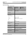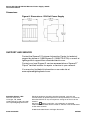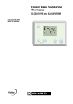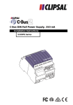
1
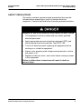
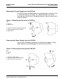
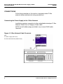
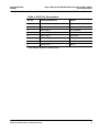
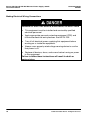
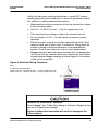
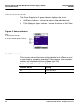
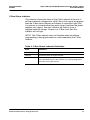
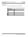
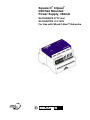
®
®
Square D Clipsal
DIN Rail Mounted
Power Supply, 350mA
SLC5500HPS 277V and
SLC5500TPS 110-120V
For Use with Wired C-Bus™ Networks
Square D® Clipsal® DIN Rail Mounted Power Supply, 350mA
Instruction Bulletin
63249-420-204A2
04/2007
HAZARD CATEGORIES AND SPECIAL SYMBOLS
Read these instructions carefully and look at the equipment to become
familiar with the device before trying to install, operate, service, or maintain
it. The following special messages may appear throughout this bulletin or on
the equipment to warn of potential hazards or to call attention to information
that clarifies or simplifies a procedure.
The addition of either symbol to a “Danger” or “Warning” safety label
indicates that an electrical hazard exists which will result in personal injury if
the instructions are not followed.
This is the safety alert symbol. It is used to alert you to potential personal
injury hazards. Obey all safety messages that follow this symbol to avoid
possible injury or death.
Danger indicates an immediately hazardous situation which, if not
avoided, will result in death or serious injury.
Warning indicates a potentially hazardous situation which, if not
avoided, can result in death or serious injury.
Caution indicates a potentially hazardous situation which, if not
avoided, can result in minor or moderate injury.
Caution, used without the safety alert symbol, indicates a potentially
hazardous situation which, if not avoided, can result in property
damage or improper operation.
NOTE: Provides additional information to clarify or simplify a procedure.
2
© 2007 Schneider Electric. All Rights Reserved.
63249-420-204A2
04/2007
Square D® Clipsal® DIN Rail Mounted Power Supply, 350mA
Instruction Bulletin
PLEASE NOTE
Electrical equipment should be installed, operated, serviced, and maintained
only by qualified personnel. This document is not intended as an instruction
manual for untrained persons. No responsibility is assumed by Square D for
any consequences arising out of the use of this manual.
Class B FCC Statement
This equipment has been tested and found to comply with the limits for a
Class B digital device, pursuant to Part 15 of the FCC Rules. These limits
are designed to provide reasonable protection against harmful interference
in a residential installation. This equipment generates, uses, and can radiate
radio frequency energy and, if not installed and used in accordance with the
instructions, may cause harmful interference to radio communications.
However, there is no guarantee that interference will not occur in a particular
installation. If this equipment does cause harmful interference to radio or
television reception, which can be determined by turning the equipment off
and on, the user is encouraged to try to correct the interference by one or
more of the following measures:
•
Reorient or relocate the receiving antenna.
•
Increase the separation between the equipment and receiver.
•
Connect the equipment into an outlet on a circuit different from that to
which the receiver is connected.
•
Consult the dealer or an experienced radio/TV technician for help.
© 2007 Schneider Electric. All Rights Reserved.
3
Square D® Clipsal® DIN Rail Mounted Power Supply, 350mA
Instruction Bulletin
63249-420-204A2
04/2007
INTRODUCTION
The 5500PS series Power Supply provides operating power for
units on the C-Bus™ network. It is DIN rail mounted for easy
installation. The C-Bus network connection is conveniently achieved
through the use of RJ45 connectors, allowing C-Bus units to be
quickly added to the network.
The 5500PS series Power Supply is available in these
configurations:
•
SLC5500HPS 350mA (277V*, 50/60Hz)
•
SLC5500TPS 350mA (110-120V*, 50/60Hz)
* Nominal Supply Voltage ± 10%.
Before You Begin
Before installing the Power Supply, inspect it carefully. Verify the
catalog number on the box label.
Table 1: Contents of the Box
Part Number
Description
Quantity
SLC5500HPS
350mA (277V, 50/60Hz)
1
or
SLC5500TPS
RJ5CB300PL
4
350mA (110-120V, 50/60Hz)
Rubber RJ45 terminal plugs
3
C-bus network cable, 15.7 in. (400 mm)
1
© 2007 Schneider Electric. All Rights Reserved.
63249-420-204A2
04/2007
Square D® Clipsal® DIN Rail Mounted Power Supply, 350mA
Instruction Bulletin
SAFETY PRECAUTIONS
This section contains important safety precautions that must be
followed before attempting to install or maintain electrical
equipment. Carefully read and follow the safety precautions below.
HAZARD OF ELECTRIC SHOCK, EXPLOSION, OR ARC FLASH
•
This equipment must be installed and serviced by qualified
electrical personnel.
•
Apply appropriate personal protective equipment (PPE) and
follow safe electrical work practices. See NFPA 70E.
•
Turn off all electrical power supplying this equipment before
working on or inside the equipment.
•
Always use a properly rated voltage sensing device to confirm
that power is off.
•
Replace all devices, doors, and covers before turning on power
to this equipment.
Failure to follow these instructions will result in death or
serious injury.
© 2007 Schneider Electric. All Rights Reserved.
5
Square D® Clipsal® DIN Rail Mounted Power Supply, 350mA
Instruction Bulletin
63249-420-204A2
04/2007
INSTALLATION
Follow the steps in the sections below to properly install the Power
Supply.
Network Considerations
•
Plan your C-Bus network installation carefully. It is
recommended that power supplies be distributed evenly along
the C-Bus network.
•
Each Power Supply provides 350mA of isolated 36Vdc class 2
voltage to the C-Bus network. Each Power Supply can support
up to 15 C-Bus devices at approximately 22mA per unit (PC
Interface draws 32mA).
•
The installer should verify that an adequate number of C-Bus
network Power Supplies are installed to support the connected
devices. The total number of units connected to the C-Bus
network must not exceed 350mA. Consult the C-Bus™
Calculator – Network Design Verification Software Utility to
determine the total network current load.
•
A maximum of five (5) 5500PS series Power Supply units may
be connected on a single C-Bus network. Other units
incorporating a C-Bus Power Supply may be used in conjunction
with this Power Supply provided that the total available current
supplied to the network does not exceed 2000mA (2A).
HAZARD OF IMPROPER OPERATION OR SYSTEM DAMAGE.
Use only C-Bus Power Supplies with units connected to a C-Bus
network.
Failure to follow this instruction can result in improper
operation or system damage.
6
© 2007 Schneider Electric. All Rights Reserved.
63249-420-204A2
04/2007
Square D® Clipsal® DIN Rail Mounted Power Supply, 350mA
Instruction Bulletin
Mounting the Power Supply onto the DIN Rail
The DIN-rail units are designed to be installed onto a standard 1.38
in. (35 mm) DIN rail. To mount (i.e., attach) the DIN unit, hook it
onto the top of the DIN rail. Swing the bottom of the unit down until it
clicks into place.
Figure 1: Mounting the Unit onto the DIN Rail
KEY:
A. DIN rail
B. DIN-rail unit
1. Hook the unit onto the top of the DIN rail
2. Swing the bottom of the unit down
3. Mounted unit
Removing the Power Supply from the DIN Rail
Use a small flat-blade screwdriver to pull either the upper or lower
slide release out and disengage the unit from the DIN rail.
Figure 2: Removing the Unit from the DIN Rail
KEY:
A. DIN rail
B. Unit
1. Pull out the slide release
2. Pull the unit away from the DIN rail
3. Lift the unit away from the rail
© 2007 Schneider Electric. All Rights Reserved.
7
Square D® Clipsal® DIN Rail Mounted Power Supply, 350mA
Instruction Bulletin
63249-420-204A2
04/2007
CONNECTIONS
Follow the procedures in this section to properly make C-Bus
network cable and electrical wiring connections.
Connecting the Power Supply to the C-Bus Network
Installation requires connection to the unshielded twisted pair C-Bus
Network Cable. Use a Category 5 data cable.
NOTE: Install rubber plugs provided in any unused RJ45 cable
terminals.
Figure 3: C-Bus Network Cable Terminals
KEY:
A. Power supply (front view)
B. RJ45 cable terminals (bottom view)
8
© 2007 Schneider Electric. All Rights Reserved.
63249-420-204A2
04/2007
Square D® Clipsal® DIN Rail Mounted Power Supply, 350mA
Instruction Bulletin
Table 2: RJ45 Pin Connections
RJ Pin
C-Bus Connection
Color
1
Remote ON*
Green/White
2
Remote ON*
Green
3
C-Bus Neg (-)
Orange/White
4
C-Bus Pos (+)
Blue
5
C-Bus Neg (-)
Blue/White
6
C-Bus Pos (+)
Orange
7
Remote OFF*
Brown/White
8
Remote OFF*
Brown
*Not used in 5500PS series units
© 2007 Schneider Electric. All Rights Reserved.
9
Square D® Clipsal® DIN Rail Mounted Power Supply, 350mA
Instruction Bulletin
63249-420-204A2
04/2007
Making Electrical Wiring Connections
HAZARD OF ELECTRIC SHOCK, EXPLOSION, OR ARC FLASH
•
This equipment must be installed and serviced by qualified
electrical personnel.
•
Apply appropriate personal protective equipment (PPE) and
follow safe electrical work practices. See NFPA 70E.
•
Turn off all electrical power supplying this equipment before
working on or inside the equipment.
•
Always use a properly rated voltage sensing device to confirm
that power is off.
•
Replace all devices, doors, and covers before turning on power
to this equipment.
Failure to follow these instructions will result in death or
serious injury.
10
© 2007 Schneider Electric. All Rights Reserved.
63249-420-204A2
04/2007
Square D® Clipsal® DIN Rail Mounted Power Supply, 350mA
Instruction Bulletin
Verify that the power supplying the system is turned OFF before
handling electrical power conductors. Follow the guidelines listed in
this section for making electrical connections.
•
Make electrical wiring connections to the line terminals as shown
in the illustration below.
•
Use #12 - 16 AWG (3.1mm² - 1.3mm²) copper wire only.
•
Take care that wire cuttings or debris do not enter the unit.
•
Do not exceed 1.0 ft-lb. (1.4 nM) maximum torque on power
terminals.
•
Electrical power conductors must be separated from the C-Bus
network cable and all other class 2 conductors. Wiring must be
routed to maintain minimum separation or be separated by
barriers. Consult your electrical code for local requirements.
•
Megger testing of electrical power terminals will not damage this
unit. Since this unit contains electronic components, the installer
should interpret Megger readings with due regards to the nature
of the circuit connection.
Figure 4: Electrical Wiring Terminals
KEY:
A. Electrical wiring terminals
NOTE: Use #12 - 16 AWG (3.1mm² - 1.3mm²) copper wire only.
HAZARD OF EQUIPMENT DAMAGE
Do not Megger® test C-Bus data cabling or terminals. Megger testing
can result in equipment damage.
Failure to follow this instruction will result in damage to the
C-Bus network.
© 2007 Schneider Electric. All Rights Reserved.
11
Square D® Clipsal® DIN Rail Mounted Power Supply, 350mA
Instruction Bulletin
63249-420-204A2
04/2007
STATUS INDICATORS
The Power Supply has 2 green indicator lights on the front.
•
Unit Status Indicator - shows the status of the individual unit.
•
C-Bus Network Status Indicator - shows the status of the C-Bus
network at this unit.
Figure 5: Status Indicators
KEY:
A. Unit Status Indicator
B. C-Bus Network Status Indicator
Unit Status Indicator
This indicator shows the status of the individual unit. When the unit
is connected to a properly operating C-Bus network, the unit status
indicator will display a continuous green light (ON).
Table 3: Unit Status Indicator Definitions
12
Indicator Status
Meaning
On
Normal operation
Off
No C-Bus connected
© 2007 Schneider Electric. All Rights Reserved.
63249-420-204A2
04/2007
Square D® Clipsal® DIN Rail Mounted Power Supply, 350mA
Instruction Bulletin
C-Bus Status Indicator
This indicator shows the status of the C-Bus network at the unit. If
sufficient network voltage and a valid C-Bus clock signal are present
then the C-Bus status indicator will display a continuous light (ON).
If a network is connected that has more current load than the power
supplies can support, then this indicator will flash to show a
marginal network voltage. If there is no C-Bus clock then this
indicator will not light.
NOTE: The C-Bus indicator does not function when standalone
programming is being performed on a unit powered by the C-Bus
network.
Table 4: C-Bus Status Indicator Definitions
State
Definition
ON
Power on and functional
Flashing
Insufficient power to support network
OFF
No external electrical power source. Indicator does not function if
unit is powered only by C-Bus network, e.g., during configuration
No C-Bus clock signal present
© 2007 Schneider Electric. All Rights Reserved.
13
Square D® Clipsal® DIN Rail Mounted Power Supply, 350mA
Instruction Bulletin
63249-420-204A2
04/2007
STANDARDS
The Power Supply complies with the following Standards:
Table 5: U.S. and Canadian Product Safety Standards and U.S.
FCC Regulations
Standards/Regulations
14
Title
CSA C22.2 No. 205
Signal Equipment
UL916
Energy Management Equipment
FCC Part 15
Class B Digital Device for Home or Office Use
© 2007 Schneider Electric. All Rights Reserved.
63249-420-204A2
04/2007
Square D® Clipsal® DIN Rail Mounted Power Supply, 350mA
Instruction Bulletin
SPECIFICATIONS
Table 6: Specifications
Catalog Number
SLC5500HPS
SLC5500TPS
Nominal Supply Voltage
277Vac ± 10%
110-120Vac ± 10%
Frequency Range(s)
50/60Hz
C-Bus Supply Voltage
15-36V DC @ 350mA
C-Bus Current Output
Sources 350mA to the C-Bus network with load-side
power connected
DC Output Resistance
(approximate)
22 Ohms
AC Input Impedance
>60k Ohms @1kHz
Electrical Isolation
3.75kV RMS from C-Bus to Line voltage
Status Indicators
C-Bus Network Status
On
Voltage =/> 20V DC
Flashing
Voltage < 20V DC
Off
Voltage < 15V DC or no clock signal
Unit:
On
Normal
Off
No C-bus connected
Max. Number of Units on a
Single C-Bus Network
5
Load Rating
350mA (Can support up to 15 units @ 22mA each on
the C-Bus Network.
Power Supply Type
High Impedance Switch Mode Power Supply
Quiescent Power
15 Watts Max.
Warm Up Time
3 sec
Dimensions
2.84 x 3.35 x 2.6 in. (72 x 85 x 65 mm)
Line-side Terminals
Accommodates #12 - 16 AWG
(3.1mm² - 1.3mm²) copper wire only.
Weight
7oz (200g)
C-Bus Connections
2 x RJ45 sockets
Operating Temperature Range
32 - 104° F (0 - 40° C)
Operating Humidity Range
95% RH, Non-condensing
© 2007 Schneider Electric. All Rights Reserved.
15
Square D® Clipsal® DIN Rail Mounted Power Supply, 350mA
Instruction Bulletin
Dimensions
Figure 6: Dimensions - DIN Rail Power Supply
SUPPORT AND SERVICE
Contact the Square D Customer Information Center for technical
support by phone at 1-888-Square D (1-888-778-2733) or e-mail at
[email protected].
®
Contact your local Square D service representative or Square D
Clipsal® certified installer for repairs or service to your network.
You may also find helpful information on our web site at
www.squaredlightingcontrol.com.
Schneider Electric, USA
295 Tech Park Drive
La Vergne, TN, 37086
1-888-SquareD (1-888-778-2733)
www.squaredlightingcontrol.com
Electrical equipment should be installed, operated, serviced, and
maintained only by qualified personnel. No responsibility is assumed by
Schneider Electric for any consequences arising out of the use of this
material.
Square D,
, Clipsal, and C-Bus, are trademarks or registered
trademarks of Schneider Electric and/or its affiliates in the United States
and/or other countries.
© 2007 Schneider Electric. All Rights Reserved.
63249-420-204A2
04/2007