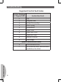
1
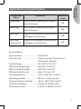
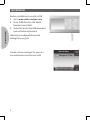
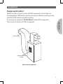
Emerson Inspire™ 1HDEZ-1521 Installation Instructions Equipment Control TROUBLESHOOTING Thermostat/Interface FAILURE TO READ AND FOLLOW ALL INSTRUCTIONS CAREFULLY BEFORE INSTALLING OR OPERATING THIS CONTROL COULD CAUSE PERSONAL INJURY AND/OR PROPERTY DAMAGE. ! CAUTION To prevent electrical shock and/or equipment damage, disconnect electric power to system at main fuse or circuit breaker box until installation is complete. ! WARNING Thermostat installation and all components of the control system shall conform to Class II circuits per the NEC code. ATTENTION: MERCURY NOTICE This product does not contain mercury. However, this product may replace a product that contains mercury. Mercury and products containing mercury must not be discarded in household trash. Do not touch any spilled mercury. Wearing non-absorbent gloves, clean up any spilled mercury and place in a sealed container. For proper disposal of a product containing mercury or a sealed container of spilled mercury, place it in a suitable shipping container. Refer to www. thermostat-recycle.org for location to send product containing mercury. Index Applications and Specifications Installation Advanced Installer Menu Main Menu Troubleshooting 2 Page 3 4 12 20 26 APPLICATIONS & SPECIFICATIONS Applications and Specifications Configuration Options Applications Maximum Stages Single Stage Gas, Oil, Electric, Heat Only, Cool Only or Heat Cool Systems 1/1 Multi Stage Gas, Oil, Electric, Heat Only, Cool Only or Heat Cool Systems 2/2 Heat Pump Single or Two Compressor Systems with up to 2 Stages of Aux / Em Heat 4/2 Heat Pump with Dual Fuel Single or Two Compressor Systems with up to 2 Stages of Fossil fuel Heat 4/2 Electrical Rating: Input-Hardwire .............................. 20 to 30 VAC Terminal Load ............................... 1.0A per terminal, 2.5A maximum all terminals combined Setpoint Range ............................. 45° to 99°F (7° to 37°C) Differential (Single Stage) ............. Heat 0.6°F; Cool 1.2°F Differential (Multi-Stage) .............. Heat 0.6°F; Cool 1.2°F Differential (Heat Pump) ............... Heat 1.2°F; Cool 1.2°F Operating Ambient ....................... 32°F to +105°F (0° to +41°C) Operating Humidity ...................... 90% non-condensing max. Shipping Temperature Range ........ -40° to +150°F (-40° to +65°C) Dimensions Interface .................... 3-1/4"H x 6-1/8"W x 5/8"D Dimensions Control ....................... 5-1/2"H x 5-3/4"W x 1-1/2"D 3 Installation INSTALLATION Reduce installation time with a USB 1. Go to www.white-rodgers.com 2. Enter 1HDEZ-1521 in the Model Number Search field 3. Select the link for the USB download tool and follow instructions Upload pre-configured thermostat settings for every job! Create custom messages for your routine maintenance and service calls! 4 Installation Equipment Control INSTALLATION Mount on wall or exterior surface of HVAC equipment. Control has four mounting holes. Wall anchors and screws are provided for mounting on drywall. Drill 3/16" hole for drywall mounting. If mounting on equipment Do Not Mount inside HVAC equipment. Only mount on outside of HVAC equipment. Return Air Duct Supply Duct Equipment Control Module Gas Furnace Equipment 5 Installation Equipment Control Terminals Operation / Function INSTALLATION R................................................. 24 VAC Transformer RC............................................... 24 VAC Cooling Transformer* RH.............................................. 24 VAC Heating Transformer* C................................................. 24 V Transformer Common W/E............................................. Heating Stage 1 HP Aux/Em Heat Stage 1 W2.............................................. Heating Stage 2 HP Aux/Em Heat Stage 2 Y................................................. Compressor Stage 1 Y2............................................... Compressor Stage 2 G................................................. Fan Relay L Terminal................................... System Monitor Compatible with Comfort Alert Diagnostics O/B Terminal............................... Changeover Relay Heat Pump DHM........................................... Dehumidification Relay / Connection DHM2......................................... Dehumidification Relay / Connection HM.............................................. Humidification Relay / Connection HM2............................................ Humidification Relay / Connection R................................................. 24 VAC to Interface 1.................................................. Data to/from Interface 2.................................................. Data to/from Interface C................................................. 24 VAC Common to Interface RJ11............................................ Field configuration hook-up with RJ11 equipped configuration tool +.................................................. Voltage to Outdoor Sensor S................................................. Outdoor Sensor Temperature Signal -.................................................. Voltage to Outdoor Sensor *For 2 transformer systems, cut and tape off one transformer. If transformer safety circuits are only in one of the systems, remove the transformer of the system with NO safety circuits. If required, replace remaining transformer with a 75 VA Class II transformer. After disconnecting one transformer, the two commons must be jumpered together. 6 Installation LED push button switch R and C from HVAC terminal strip or system transformer Status/Fault 7-Segment LED Wiring to Thermostat + S - R RC RH C R 1 2 C RJ-11 Connection for Configuration Plug-In tool W/E W2 Y Y2 G O/B L HM HM2 DHM DHM2 Wiring to humidification equipment Wiring to dehumidification equipment DHM switch* HM switch* * To use the HVAC transformer to power humidification/dehumidification switch HM/DHM switches to “SYS” position: – Connect humidifier to HM – Connect dehumidifier to DHM If humidifier or dehumidifier have a separate transformer, switch HM or DHM switch to “DRY” position: – Connect humidifier to HM and HM2 (or) – Connect dehumidifier to DHM and DHM2 7 INSTALLATION Wiring to Sensor Wiring to indoor/outdoor equipment Installation Fig. 1 - Typical Connection of a Single Stage or Multi-Stage System * INSTALLATION SYSTEM R RH RC C Single 24 VAC 24 VAC 24 VAC Stage Power Power for Power Heating for Cooling 24 VAC Multi 24 VAC 24 VAC 24 VAC Common Stage Power Power Power Required W/E W2 Y Y2 G O/B L Heat N/A Cool N/A Fan N/A System Monitor Heat Heat Cool Cool mode mode mode mode 1st 2nd 1st 2nd stage stage stage stage NEUTRAL 120 VAC 24 VAC *Factory installed jumper between RH and RC HOT CLASS II Transformer Fig. 2 - Typical Connection of Heat Pump System up to 4 Stages Heat/2 Stages Cool * SYSTEM R RH RC C W/E W2 Y L Y2 G O/B Heat 24 VAC 24 VAC 24 VAC Aux / Aux / 1st 2nd Fan Change- System over Monitor Pump Power Power for Power 24 VAC Em Em Stage Stage Valve st Heating for Cooling 2nd Com- ComCommon 1 Required Stage Stage pres- pressor sor NEUTRAL 120 VAC 24 VAC HOT CLASS II *Factory installed jumper between RH and RC Transformer Note: Dual fuel systems W/E is fossil fuel 1st stage and W2 is fossil fuel 2nd stage. 8 Installation Wiring Guide for Equipment Accessories HM DRY R RH C Transformer HM2 HM HM2 Non-Powered Humidifier Fig. 4 - Powered Humidifier. With HM DRY switch in HM2 position, HM and HM2 provide normally open dry contact for low voltage (24V) powered humidifier connection. HM DRY RH HM HM2 HM2 Non-Powered Humidifier Fig. 5 - Powered Dehumidifier. With DHM DRY switch in DHM2 position, DHM and DHM2 provide normally open dry contact for low voltage (24V) whole house powered dehumidifier connection. RH DHM2 DHM DRY DHM DHM2 Powered Dehumidifier 9 INSTALLATION Fig. 3 - Humidifier. HM terminal provides system 24V on call for humidification Installation Wiring Guide for Equipment Accessories INSTALLATION Fig. 6 - System Dehumidification with variable speed blower. For systems where low speed requires connect to normally open 24V powered DHM terminal for low speed connection on air handler/furnace (24V removed on dehumidification call). RH DHM2 DHM Low Speed Fan DHM2 DHM DRY Fig. 7 - System Dehumidification with variable speed blower. For systems where low speed requires system 24V on dehumidification connect 24V to DHM2 with DHM DRY switch in DHM2 position and connect DHM to low speed connection on air handler/ furnace. R C Transformer 10 RH DHM2 DHM DRY DHM DHM2 Low Speed Fan INSTALLATION Installation Tabs Thermostat 1) Pull the thermostat off the base using tabs shown above. 2) Place base over wire hole in wall and mark mounting hole locations using base as a template. Drill mounting holes. 3) Fasten base snugly to wall using wall anchors and two mounting screws. Leveling is for appearance only and will not affect thermostat operation. 4) Connect wires to terminal block on base. Important: Wiring from equipment control should correspond with wiring to thermostat. (see Fig. 8) 5) Carefully line the thermostat up with the base and snap into place. 11 Installation LED push Fig. 8 - Thermostat and Equipment Control Wiring button switch Wiring to Sensor INSTALLATION R and C from HVAC terminal strip or system transformer + S - R RC RH C Status/Fault 7-Segment LED R 1 2 C Wiring to Thermostat Thermostat Base 1 2 C R Data 2 1 24 VAC (Co Power System Turn on AC power to the system. As the equipment module is found, the display will show “Equipment Control” found. If the system continues searching after a couple of minutes, check system wiring. 12 W/E W2 Y Y2 G O/B L HM HM2 DHM DHM2 DHM switch* Equipment Control RJ-11 Connection for HM switch* Configuration Plug-In tool Data 1 AC 24 V t) o H ( Thermostat R Wiring to indoor/outdoor equipment mmon 2 C Equipment Control Wiring to humidification equipment Wiring to dehumidification equipment From the Home screen press the and buttons at the same time for three seconds. Press Enter button to save any changes and display the previous menu or press Home to display the Home Screen. Items on the Advanced Installer Menu are: Communicating Devices – select system configuration options Fault Status – indicates equipment faults that have been detected USB Upload – select thermostat settings to be uploaded from a pre-loaded USB Thermostat Summary – indicates software version of thermostat Heat Pump Lockout* – disable heat pump below a selectable temperature (when using electric Aux heat) Dual Fuel Setpoint* – disable heat pump below a selectable temperature (when using fossil fuel Aux heat – dual fuel) Aux Lockout* – disable Aux heat above a selectable temperature Heat Cycle Rate – adjust the duration for a call for heating Cool Cycle Rate – adjust the duration for a call for cooling Humidity Display Adjust – off-set the humidity that is displayed Installation Test – equipment test for communicating systems only *May or may not appear in the list depending on the configuration of the system Important: Allow up to 5 minutes for menu options to become available after changing settings. 13 ADVANCED INSTALLER MENU Advanced Installer Menu Advanced Installer Menu Communicating Devices This menu item will list each piece of system equipment. Press button to select start Communicating Devices. ADVANCED INSTALLER MENU Press button to select Equipment Control. Press 14 button to select Setup. Advanced Installer Menu Use or to navigate and press button to select the equipment to be configured. Options for each type of equipment are the following: ADVANCED INSTALLER MENU Indoor GA2 – 2 stage gas furnace GA1 – 1 stage gas furnace EL2 – 2 stage electric heat EL1 – 1 stage electric heat FAN – Indoor fan only Outdoor AC2 – 2 stage A/C unit AC1 – 1 stage A/C unit HP2 – 2 stage heat pump HP1 – 1 stage heat pump ACO – no outdoor equipment Rev Valve O – use if “O” wire is available (energize the reversing valve in cooling) B – use if “B” wire is available (energize the reversing valve in heating) 15 Advanced Installer Menu HUM OFF – No humidifier equipment SYS – Humidifier, powered using 24V from system IND – Humidifier, powered using independent 24V source DHM OFF – No dehumidifier equipment SYS – Dehumidifier, powered using 24V from system IND – Dehumidifier, powered using independent 24V source LEDs on the control indicate the thermostat configuration. Remove control cover to view LEDs. To view LEDs with cover installed, break off tab on inside of cover. ADVANCED INSTALLER MENU W/E W2 Y Y2 G O/B HM 7-Segment LED for Comfort Alert and Communication Codes System RJ-11 Connection for Fig. 9 – LED locations Configuration Plug-In tool LED Color Orange Green Indoor GAS W/E W2 G Outdoor AC Y Y2 16 DHM ELEC HP Humidification HM HM2 RH Dehumification DHM DHM2 RH B O Rev Valve O/B LED Off implies functionality is disabled at the thermostat LED flashing implies corresponding function is active Advanced Installer Menu Faults Status This menu item lists current equipment fault conditions. If no faults are detected, this screen will show nothing. (See “System Fault Codes” on page 28.) USB Upload ADVANCED INSTALLER MENU The USB Upload menu displays a list of thermostat parameters that can be loaded to the thermostat from a USB memory device. If the USB port detects a USB memory device, this menu will automatically display. In the USB Upload menu, select the item to upload and press to mark the item with a red box. After all items to upload are selected, press the Upload button. If the thermostat does not find information when the Upload button is pressed, the display will indicate, “Invalid Data Found. Installation Failed!” Once the upload is accomplished, the display will indicate “Successfully Installed” for 3 seconds then will display the menu or mode prior to entering the USB upload menu. To use the USB Upload feature, go to www.white-rodgers.com, enter 1HDEZ-1521 in the Model Number Search field and select the USB download link. 17 Advanced Installer Menu Thermostat Summary Indicates the thermostat’s software and version. Heat Pump Lockout (outdoor sensor required) Available only for heat pump systems with indoor electric heat. This feature disables the heat pump and turns on auxiliary heat below the selected outdoor temperature. The temperature range is from 5° to 50°F. ADVANCED INSTALLER MENU Dual Fuel Setpoint (outdoor sensor required) If the heating system is a heat pump with auxiliary gas heat and the outdoor sensor is installed, the thermostat can monitor outside temperature to determine when to begin using the gas heat system and stop the compressor. This temperature is the Dual Fuel temperature setpoint. The Dual Fuel feature eliminates the need for a fossil fuel kit. The display will indicate 5° (default). The temperature can be adjusted to a value between 5° to 50°. The temperature will appear as °F unless °C is selected for temperature display. As long as the outside temperature is above the Dual Fuel Setpoint, the compressor will operate. When the temperature drops below the setting the thermostat will start the gas heat and shut off the compressor. 18 Advanced Installer Menu Aux Lockout Temperature (outdoor sensor required) Available for heat pump systems. This setting is the maximum outdoor temperature that is acceptable for auxiliary heat to be used. Heat Cycle Rate Anticipation for heat cycle can be adjusted. Default setting is Medium. If you wish to have longer heat cycles, change to Slow. For shorter heat cycles change to Fast. ADVANCED INSTALLER MENU Cool Cycle Rate Anticipation for cool cycle can be adjusted. Default setting is Medium. If you wish to have longer cool cycles, change to Slow. For shorter cool cycles change to Fast. Humidity Display Adjust Press or to offset the displayed humidity from the actual. 19 Advanced Installer Menu Installation Test Performs an equipment test to verify proper installation and performance. Only operable on communicating systems with ClimateTalk™. Check System Operation ADVANCED INSTALLER MENU Heating System 1. Press SYSTEM button until Heat is displayed. 2. Press to adjust thermostat setting 1° above room temperature. The heating system should begin to operate and the display will indicate Heat On. 3. If the heating system has additional stages, adjust the thermostat setting to 3°F (2°C) or more above the actual temperature. The next heat stage will energize. 4. Press to adjust thermostat setting below room temperature. The heating system should stop operating. Cooling System 1. Press SYSTEM button until COOL is displayed. 2. Press to adjust thermostat setting below room temperature. The cooling system should begin to operate and the display will indicate Cool On. 3. If the cooling system has additional stages, adjust the temperature to 3°F (2°C) or more below the actual. The second cool stage will energize within 10 seconds. 4. Press to adjust thermostat setting above room temperature. The cooling system should stop operating. Fan Operation 1. Press FAN button until Fan On is displayed. The fan should begin to operate. 2. Press FAN button to change the display to Fan Auto. The fan should stop operating as long as there is no call for heat or cool. 20 Main Menu Navigating through your thermostat menus Your thermostat features a simplified easy to understand menu structure. • Press to enter the Main Menu • Highlight a menu item using the buttons or • Enter the item by pressing • Use the or and the or to change menu items and settings • Press the Home button to display the Home Screen. • Press the Enter button to save any changes you have made and display the previous menu item. • If no button is pressed for two minutes, you will return to the home screen without saving changes. MAIN MENU Clock and Display Settings Time and Date Select and enter the time and date to be displayed. Display Settings Adjust the brightness and color theme for the display. Turn the keypad backlight and auto-dimmer, on or off. 21 Main Menu Time and Day Display When turned on, the current time and day are displayed on the home screen. Outdoor Temp Display When turned on, the outdoor temperature is displayed on the home screen (for use with outdoor sensor only). Humidity Display When turned on, the sensed humidity is displayed on the home screen. Alert Info Detail When turned on, provides additional information for maintenance and service reminders. Heating Program • On the Main Menu, highlight and enter Heating Program • Select the days of the week to be changed. MAIN MENU • Press or to change the highlighted Time or Temperature to your desired settings • Press or to highlight the next time or temperature • Set all times and temperatures for all periods 22 Main Menu • When you have completed setting all times and temperatures, press Enter to save and display the Heating Program menu. A checkmark appears to indicate the portion of schedule you have programmed Cooling Program After entering Heating Program, press to highlight “Switch to Cool Program” and press , or enter Cooling Program on the Main Menu. Factory Pre-Programmed Heating and Cooling Schedule Heating Program Cooling Program Wake Up Leave for Work Return Home Go to Bed (Morning) (Day) (Evening) (Night) 6:00 70oF 8:00 AM 62oF 5:00 PM 70oF 10:00 PM 62oF AM 6:00 75oF 8:00 AM 83oF 5:00 PM 75oF 10:00 PM 78oF AM Thermostat Settings MAIN MENU Additional thermostat operating settings are found in the Thermostat Settings Menu. In the Main Menu highlight and enter Thermostat Settings. 23 Main Menu Program – Default is On. Select Off to disable the heating and cooling programs and maintain a constant temperature 24 hours a day. Air Filter Maintenance / Service Reminder / Humidifier Maintenance Default for each is Off. When set to On, a maintenance reminder will appear on the home screen when the system has run for the selected amount of time. The length of time for the maintenance reminder can be selected to a setting of 1 to 12 months. Use or . to select On or Off. When On is selected, set time of maintenance period using and . MAIN MENU °F or °C – Default is °F. Select temperature display to be Fahrenheit or Celsius. 24 Main Menu Beeper – Default is On. Turns audible prompt on to indicate when a button is pressed. MAIN MENU Cycle Humidifier – Default if Off. This feature provides an option that reduces the water usage by up to 50% when a flow-through humidifier is controlled by the thermostat. It is recommended for use on flow-through humidifiers only. When turned On, the humidifier will cycle to turn off for 10 minutes after it has run for 10 minutes. The blower and/ or furnace will continue to run during the humidifier off period. Auto Humidity Reduction – Default is Off. Prevents condensation from forming inside the home when the HVAC system is in heat mode. The Low setting provides a minimum amount of humidity reduction and the High setting provides a maximum. 25 Main Menu Comfort or Dehum – Default is Off. Selecting either Comfort or Dehum will automatically reduce indoor humidity with a call for cooling if humidity is 2% above the humidity setpoint. If Comfort is selected, the system will slow the fan speed (variable speed blowers only) to increase the dehumidification process and cool based on the temperature setpoint. If Dehum is selected, the system makes the dehumidification a priority over temperature. This setting uses more energy and may over-cool the space by up to 3° to achieve the desired humidity level. If Off is selected the system will control temperature to the cooling setpoint. MAIN MENU EMR (Energy Management Recovery) Default is On. With EMR selected On, the heating or cooling system will start early so the temperature in your home is at the desired temperature at the beginning of the program period. If set to Off, the system will not start until the beginning of the program period. Maximum Heat Setpoint Temp. Default is 99°. Minimum Cool Setpoint Temp. – Default is 45°. These settings are the highest temperature limit in Heat mode or the lowest temperature limit in Cool mode. Select a setting of 99° to 45° for the maximum heating temperature or 45° to 99° for the minimum cooling temperature. 26 Main Menu Temperature Display Adjust – Default is 0°. Your thermostat was accurately calibrated at the factory. However, this option allows you to change the humidity or temperature displayed to match other thermostats in your home. Dehumidification Setpoint – Default is 95%. Setpoint is the percent humidity that the cooling system will attempt to maintain. Only available when dehumidification equipment is enabled (see Communicating Devices in Advanced Installer Menu). MAIN MENU Humidity Setpoint – Default is 20%. Humidity setpoint is the percent humidity that the heating system and humidifier will attempt to maintain in Heating. Only available when humidification equipment is enabled (see Communicating Devices in Advanced Installer Menu). 27 Troubleshooting Reset Operation If a voltage spike or static discharge blanks out the display or causes erratic thermostat operation, you can reset the system by performing a power reset. Note: Be sure to record the user’s Main Menu settings. When thermostat is reset, Main Menu and Programming will reset to factory settings. (Installer’s equipment setup options will NOT be affected by the reset.) To reset the programming, clock and configuration settings, press and and the SYSTEM touch keys simultaneously and hold until the screen resets. Symptom Possible Cause Correction Action No Heat/No Cool/ 1.Blown fuse or tripped Replace fuse or reset breaker. No Fan circuit breaker. (common 2.Power switch to OFF. Turn switch to ON. Replace door panel in proper problems) 3.Furnace blower position to engage safety compartment door or panel loose or not interlock or door switch. Check connections at the properly installed. 4.Loose connection to thermostat and equipment control. Thermostat base system. should be installed on a flat surface to ensure a good connection with the thermostat. No Heat TROUBLESHOOTING 28 1.Pilot light not lit. 2.Furnace Lock-Out Condition. Heat may also be intermittent. 3.Heat pump system requires service. Re-light pilot. Many furnaces have safety devices that shut down when a lock-out condition occurs. If the heat works intermittently contact the furnace manufacturer. Troubleshooting Possible Cause No Cool 1.Cooling system requires service. Heat, Cool or Fan 1.Possible short in Runs Constantly wiring. 2.Possible short in thermostat. 3.Possible short in heat/ cool/fan system. 4.FAN Switch set to Fan ON. Correction Action Check each wire connection to verify they are not shorted or touching together. No bare wire should stick out from under terminal block. Try resetting the thermostat as described above. If the condition persists, the manufacturer of your system can instruct you on how to test the Heat/Cool system for correct operation. If the system operates correctly, replace the thermostat. Displayed Thermostat Reading and Thermometer Disagree 1.Thermostat display setting requires adjustment. The display can be adjusted +/- 5 degrees. Adjust the Temperature Display Adjust settings within Thermostat Settings (see Main Menu options). Furnace (Air Conditioner) Cycles Too Fast or Too Slow (narrow or wide temperature swing) 1.The location of the thermostat and/or the size of the Heating System may be influencing the cycle rate. Adjust the Heat Cycle Rate or Cool Cycle Rate in the Advanced Installer Menu. 29 TROUBLESHOOTING Symptom Troubleshooting Equipment Control Fault Codes Number Displayed in 7 Segment LED P 1 2 3 4 5 6 7 8 9 E C TROUBLESHOOTING 30 Comfort Alert Fault Trip Long Run Time System Pressure Trip Short Cycling Locked Rotor Open Circuit Open Start Circuit Open Run Circuit Welded Contactor Low Voltage System Communication Codes Communication Error For 30 seconds after Communication established, then blank PART NO. 37-7343B Replaces 37-7343A 1312 White-Rodgers is a business of Emerson Electric Co. The Emerson logo is a trademark and service mark of Emerson Electric Co. www.white-rodgers.com www.emersonclimate.com