1
Datacard® SR200 & SR300 Card Printers
and LM200 & LM300 Laminators
User’s Guide
March 2014
Part No. 527473-001, Rev. A
Notice
Please do not attempt to operate or repair this equipment without adequate training. Any use, operation or repair you perform that is not in accordance with the information contained in this documentation is at your own risk.
These products conform to regulatory requirements as specified in North America, Europe, and Asia. Refer to “Compliance Statements” on page iii for more information. Trademark Acknowledgments
Datacard is a registered trademark and service mark of DataCard Corporation in the United States and other countries.
MasterCard is a registered trademark of MasterCard International Incorporated.
Visa is a registered trademark of Visa International Service Association.
Adobe and Reader are registered trademarks of Adobe Systems Incorporated.
Windows is a registered trademark of Microsoft Corporation.
All other product names are the property of their respective owners.
Proprietary Notice
The design and information contained in these materials are protected by US and international copyright laws.
All drawings and information herein are the property of DataCard Corporation. All unauthorized use and reproduction is prohibited. Datacard Group
11111 Bren Road West
Minnetonka, MN 55343‐9015
Phone: 952‐933‐1223
Fax: 952‐933‐7971
www.datacard.com
© 2014 DataCard Corporation. All rights reserved.
ii
Compliance Statements
Liability Statement
The WARNING and CAUTION labels have been placed on the equipment for your safety. Please do not attempt to operate or repair this equipment without adequate training. Any use, operation or repair in contravention of this document is at your own risk. Safety
All Datacard® products are built to strict safety specifications in accordance with CSA/UL60950‐1 requirements and the Low Voltage Directive 2006/95/EC. Therefore, safety issues pertaining to operation and repair of Datacard® equipment are primarily environmental and human interface.
The following basic safety tips are given to ensure safe installation, operation and maintenance of Datacard® equipment. • Connect equipment to a grounded power source. Do not defeat or bypass the ground lead. • Place the equipment on a stable surface (table) and ensure floors in the work area are dry and non‐slip. • Know the location of equipment branch circuit interrupters or circuit breakers and how to turn them on and off in case of emergency. • Know the location of fire extinguishers and how to use them. ABC type extinguishers may be used on electrical fires. • Know local procedures for first aid and emergency assistance at the customer facility. • Use adequate lighting at the equipment location. • Maintain the recommended temperature and humidity range in the equipment area. iii
Regulatory Compliance
Notice for USA (FCC notice)
This equipment has been tested and found to comply with the limits for Class A computing devices, pursuant to Part 15 of FCC rules. These limits are designed to provide reasonable protection against harmful interference when the equipment is operated in a commercial environment. This equipment generates, uses, and can radiate radio frequency energy. If this equipment is not installed and used in accordance with this instruction manual, it may cause harmful interference to radio communications. Operation of this equipment in a residential area is likely to cause harmful interference in which case the user will be required to correct the interference at their own expense. Changes or modifications not expressly approved by the party responsible for compliance could void the user's authority to operate the equipment.
Notice for Canada
This Device complies with Industry Canada License‐exempt RSS standard(s). Operation is subject to the following two conditions: 1) this device may not cause interference, and 2) this device must accept any interference, including interference that may cause undesired operation of the device. Cet appareil est conforme avec Industrie Canada RSS standard exemptes de licence(s). Son fonctionnement est soumis aux deux conditions suivantes: 1) ce dispositif ne peut causer des interférences, et 2) cet appareil doit accepter toute interférence, y compris les interférences qui peuvent causer un mauvais fonctionnement du dispositif.
Notice for Europe
The EU Declaration of Conformity can be found on Datacard.com
We hereby certify that this printer complies with EMC Directive2004/108/EC , R&TTE Directive 1999/5/EC, and the EU RoHS Directive EU Directive 2011/65/EC. This printer conforms to Class A of EN 55022 and to EN 301 489‐5. Operation of this equipment in a residential environment may possibly cause interference. In the event of interference, the users, at their own expense, will be required to take whatever measures are necessary to correct the problem.
Notice for China (Simplified Chinese)
警告
此为 A 级产品,在生活环境中,
该产品可能会造成无线电干扰。
在这种情况下,可能需要用户
对干扰采取切实可行的措施。
iv
Notice for Taiwan (Traditional Chinese)
Notice for Japan
Japanese Voluntary Control Council for Interference (VCCI) class A statement Korea Communications Commission (KCC) statement
California Proposition 65 Compliance
WARNING: This product contains chemicals, including lead, known to the State of California to
cause cancer, and birth defects or other reproductive harm. Wash hands after handling.
v
Revision Log
Datacard® SR200 & SR300 Card Printers and
LM200 & LM300 Laminators User’s Guide
Revision
Date
Description of Changes
A
March 2014
First release of this document
vi
Table of Contents
Chapter 1: Introduction. . . . . . . . . . . . . . . . . . . . . . . . . . . . . . . . . . . . . . . . . . . . . . . . . . . . . 1
About This Manual . . . . . . . . . . . . . . . . . . . . . . . . . . . . . . . . . . . . . . . . . . . . . . . . . . . . . . . . . . . . . 1
Related Documentation . . . . . . . . . . . . . . . . . . . . . . . . . . . . . . . . . . . . . . . . . . . . . . . . . . . . . . . . . 1
Whom to Call for Assistance . . . . . . . . . . . . . . . . . . . . . . . . . . . . . . . . . . . . . . . . . . . . . . . . . . . . . 2
About the Card Printers . . . . . . . . . . . . . . . . . . . . . . . . . . . . . . . . . . . . . . . . . . . . . . . . . . . . . . . . . 2
The Front and Right Side of the Card Printer . . . . . . . . . . . . . . . . . . . . . . . . . . . . . . . . . . . . . 3
The Back of the Card Printer . . . . . . . . . . . . . . . . . . . . . . . . . . . . . . . . . . . . . . . . . . . . . . . . . . 4
The Inside and Left Side of the Card Printer . . . . . . . . . . . . . . . . . . . . . . . . . . . . . . . . . . . . . . 5
Card Printer LCD Panel . . . . . . . . . . . . . . . . . . . . . . . . . . . . . . . . . . . . . . . . . . . . . . . . . . . . . . . 6
About the Laminators . . . . . . . . . . . . . . . . . . . . . . . . . . . . . . . . . . . . . . . . . . . . . . . . . . . . . . . . . . . 7
The Front and Rear of the Laminator . . . . . . . . . . . . . . . . . . . . . . . . . . . . . . . . . . . . . . . . . . . 7
The Left and Right Sides of the Laminator . . . . . . . . . . . . . . . . . . . . . . . . . . . . . . . . . . . . . . . 8
The Inside of the Laminator . . . . . . . . . . . . . . . . . . . . . . . . . . . . . . . . . . . . . . . . . . . . . . . . . . . 9
Laminator Operator Panel . . . . . . . . . . . . . . . . . . . . . . . . . . . . . . . . . . . . . . . . . . . . . . . . . . . 10
Chapter 2: Using the Printer and Laminator . . . . . . . . . . . . . . . . . . . . . . . . . . . . . . . . . . . 11
Before You Begin. . . . . . . . . . . . . . . . . . . . . . . . . . . . . . . . . . . . . . . . . . . . . . . . . . . . . . . . . . . . . .
Loading Supplies. . . . . . . . . . . . . . . . . . . . . . . . . . . . . . . . . . . . . . . . . . . . . . . . . . . . . . . . . . . . . .
Loading Cards . . . . . . . . . . . . . . . . . . . . . . . . . . . . . . . . . . . . . . . . . . . . . . . . . . . . . . . . . . . . .
Removing the Card Hopper and Cards. . . . . . . . . . . . . . . . . . . . . . . . . . . . . . . . . . . . .
Replacing the Card Hopper . . . . . . . . . . . . . . . . . . . . . . . . . . . . . . . . . . . . . . . . . . . . . .
Adjusting Card Thickness . . . . . . . . . . . . . . . . . . . . . . . . . . . . . . . . . . . . . . . . . . . . . . . . .
Loading an Ink Ribbon . . . . . . . . . . . . . . . . . . . . . . . . . . . . . . . . . . . . . . . . . . . . . . . . . . . . . .
Loading Retransfer Film. . . . . . . . . . . . . . . . . . . . . . . . . . . . . . . . . . . . . . . . . . . . . . . . . . . . . .
Loading Top-Side Laminate Film . . . . . . . . . . . . . . . . . . . . . . . . . . . . . . . . . . . . . . . . . . . . . .
Loading Bottom-Side Laminate Film . . . . . . . . . . . . . . . . . . . . . . . . . . . . . . . . . . . . . . . . . . .
Powering On . . . . . . . . . . . . . . . . . . . . . . . . . . . . . . . . . . . . . . . . . . . . . . . . . . . . . . . . . . . . . . . . .
Checking the PC Connection . . . . . . . . . . . . . . . . . . . . . . . . . . . . . . . . . . . . . . . . . . . . . . . .
Checking the Laminator Connection . . . . . . . . . . . . . . . . . . . . . . . . . . . . . . . . . . . . . . . . . .
Powering On the Laminator . . . . . . . . . . . . . . . . . . . . . . . . . . . . . . . . . . . . . . . . . . . . . . . . . .
Powering On the Printer . . . . . . . . . . . . . . . . . . . . . . . . . . . . . . . . . . . . . . . . . . . . . . . . . . . . .
Initializing the Ink Ribbon and Retransfer Film . . . . . . . . . . . . . . . . . . . . . . . . . . . . . . . . . . .
Printing Cards . . . . . . . . . . . . . . . . . . . . . . . . . . . . . . . . . . . . . . . . . . . . . . . . . . . . . . . . . . . . . . . .
Printing Cards Using ID Software . . . . . . . . . . . . . . . . . . . . . . . . . . . . . . . . . . . . . . . . . . . . . .
Printing Cards From a PC Application. . . . . . . . . . . . . . . . . . . . . . . . . . . . . . . . . . . . . . . . . .
12
12
12
13
14
14
15
16
17
18
19
19
20
20
21
22
22
23
23
Chapter 3: Printer and Laminator Settings. . . . . . . . . . . . . . . . . . . . . . . . . . . . . . . . . . . . . 25
Introduction to Printer and Laminator Settings . . . . . . . . . . . . . . . . . . . . . . . . . . . . . . . . . . . . . .
Printing Properties . . . . . . . . . . . . . . . . . . . . . . . . . . . . . . . . . . . . . . . . . . . . . . . . . . . . . . . . . . . . .
Printing Preferences . . . . . . . . . . . . . . . . . . . . . . . . . . . . . . . . . . . . . . . . . . . . . . . . . . . . . . . . . . .
Setup Tab . . . . . . . . . . . . . . . . . . . . . . . . . . . . . . . . . . . . . . . . . . . . . . . . . . . . . . . . . . . . . . . . .
Saving Settings. . . . . . . . . . . . . . . . . . . . . . . . . . . . . . . . . . . . . . . . . . . . . . . . . . . . . . . . . .
vii
26
26
27
27
28
Loading Settings . . . . . . . . . . . . . . . . . . . . . . . . . . . . . . . . . . . . . . . . . . . . . . . . . . . . . . . .
Print Tab . . . . . . . . . . . . . . . . . . . . . . . . . . . . . . . . . . . . . . . . . . . . . . . . . . . . . . . . . . . . . . . . . .
Look Up Table . . . . . . . . . . . . . . . . . . . . . . . . . . . . . . . . . . . . . . . . . . . . . . . . . . . . . . . . . .
Color Adjustment . . . . . . . . . . . . . . . . . . . . . . . . . . . . . . . . . . . . . . . . . . . . . . . . . . . . . . .
UV Ink . . . . . . . . . . . . . . . . . . . . . . . . . . . . . . . . . . . . . . . . . . . . . . . . . . . . . . . . . . . . . . . . .
Priority of Data . . . . . . . . . . . . . . . . . . . . . . . . . . . . . . . . . . . . . . . . . . . . . . . . . . . . . . . . . .
Page Split . . . . . . . . . . . . . . . . . . . . . . . . . . . . . . . . . . . . . . . . . . . . . . . . . . . . . . . . . . . . . .
Security Erase. . . . . . . . . . . . . . . . . . . . . . . . . . . . . . . . . . . . . . . . . . . . . . . . . . . . . . . . . . .
Printing Area Settings . . . . . . . . . . . . . . . . . . . . . . . . . . . . . . . . . . . . . . . . . . . . . . . . . . . .
Printer Settings . . . . . . . . . . . . . . . . . . . . . . . . . . . . . . . . . . . . . . . . . . . . . . . . . . . . . . . . . .
Encode Tab . . . . . . . . . . . . . . . . . . . . . . . . . . . . . . . . . . . . . . . . . . . . . . . . . . . . . . . . . . . . . . .
Laminate Tab . . . . . . . . . . . . . . . . . . . . . . . . . . . . . . . . . . . . . . . . . . . . . . . . . . . . . . . . . . . . . .
Configuration Tab . . . . . . . . . . . . . . . . . . . . . . . . . . . . . . . . . . . . . . . . . . . . . . . . . . . . . . . . . .
Version Tab . . . . . . . . . . . . . . . . . . . . . . . . . . . . . . . . . . . . . . . . . . . . . . . . . . . . . . . . . . . . . . . .
Using the Status Monitor . . . . . . . . . . . . . . . . . . . . . . . . . . . . . . . . . . . . . . . . . . . . . . . . . . . . . . . .
Opening the Status Monitor . . . . . . . . . . . . . . . . . . . . . . . . . . . . . . . . . . . . . . . . . . . . . . . . . .
Closing the Status Monitor . . . . . . . . . . . . . . . . . . . . . . . . . . . . . . . . . . . . . . . . . . . . . . . . . . .
Printer Status Tab . . . . . . . . . . . . . . . . . . . . . . . . . . . . . . . . . . . . . . . . . . . . . . . . . . . . . . . . . . .
Printer Setting Tab . . . . . . . . . . . . . . . . . . . . . . . . . . . . . . . . . . . . . . . . . . . . . . . . . . . . . . . . . .
Retransfer Tab . . . . . . . . . . . . . . . . . . . . . . . . . . . . . . . . . . . . . . . . . . . . . . . . . . . . . . . . . . . . .
Bend Remedy Tab . . . . . . . . . . . . . . . . . . . . . . . . . . . . . . . . . . . . . . . . . . . . . . . . . . . . . . . . . .
Media Setting Tab . . . . . . . . . . . . . . . . . . . . . . . . . . . . . . . . . . . . . . . . . . . . . . . . . . . . . . . . . .
Property Tab . . . . . . . . . . . . . . . . . . . . . . . . . . . . . . . . . . . . . . . . . . . . . . . . . . . . . . . . . . . . . . .
Laminator Tab . . . . . . . . . . . . . . . . . . . . . . . . . . . . . . . . . . . . . . . . . . . . . . . . . . . . . . . . . . . . .
Printer Select Tab . . . . . . . . . . . . . . . . . . . . . . . . . . . . . . . . . . . . . . . . . . . . . . . . . . . . . . . . . . .
Security Lock Tab. . . . . . . . . . . . . . . . . . . . . . . . . . . . . . . . . . . . . . . . . . . . . . . . . . . . . . . . . . .
Setting up Security . . . . . . . . . . . . . . . . . . . . . . . . . . . . . . . . . . . . . . . . . . . . . . . . . . . . . .
Locking the Printer. . . . . . . . . . . . . . . . . . . . . . . . . . . . . . . . . . . . . . . . . . . . . . . . . . . . . . .
Unlocking the Printer . . . . . . . . . . . . . . . . . . . . . . . . . . . . . . . . . . . . . . . . . . . . . . . . . . . . .
Deleting the Password . . . . . . . . . . . . . . . . . . . . . . . . . . . . . . . . . . . . . . . . . . . . . . . . . . .
Changing the Password . . . . . . . . . . . . . . . . . . . . . . . . . . . . . . . . . . . . . . . . . . . . . . . . . .
Others Tab . . . . . . . . . . . . . . . . . . . . . . . . . . . . . . . . . . . . . . . . . . . . . . . . . . . . . . . . . . . . . . . .
Status Monitor Messages . . . . . . . . . . . . . . . . . . . . . . . . . . . . . . . . . . . . . . . . . . . . . . . . . . . .
Using the LCD Panel Menus . . . . . . . . . . . . . . . . . . . . . . . . . . . . . . . . . . . . . . . . . . . . . . . . . . . . .
Connection and Lock Symbols . . . . . . . . . . . . . . . . . . . . . . . . . . . . . . . . . . . . . . . . . . . . . . .
Key Functions . . . . . . . . . . . . . . . . . . . . . . . . . . . . . . . . . . . . . . . . . . . . . . . . . . . . . . . . . . . . . .
Example: Using the Printer LCD Menus . . . . . . . . . . . . . . . . . . . . . . . . . . . . . . . . . . . . . . . . .
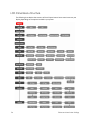
LCD Panel Menu Structure . . . . . . . . . . . . . . . . . . . . . . . . . . . . . . . . . . . . . . . . . . . . . . . . . . .
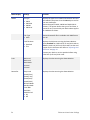
LCD Panel Menu Description . . . . . . . . . . . . . . . . . . . . . . . . . . . . . . . . . . . . . . . . . . . . . . . . .
Using a Printer Security Key. . . . . . . . . . . . . . . . . . . . . . . . . . . . . . . . . . . . . . . . . . . . . . . . . . .
Creating a Security Key . . . . . . . . . . . . . . . . . . . . . . . . . . . . . . . . . . . . . . . . . . . . . . . . . .
Unlocking the Printer . . . . . . . . . . . . . . . . . . . . . . . . . . . . . . . . . . . . . . . . . . . . . . . . . . . . .
Deleting the Security Key . . . . . . . . . . . . . . . . . . . . . . . . . . . . . . . . . . . . . . . . . . . . . . . . .
Applying a Second Retransfer Layer. . . . . . . . . . . . . . . . . . . . . . . . . . . . . . . . . . . . . . . . . . .
Laminator Status and Settings . . . . . . . . . . . . . . . . . . . . . . . . . . . . . . . . . . . . . . . . . . . . . . . . . . .
viii
28
29
29
30
30
32
32
34
35
36
36
36
37
37
38
38
40
40
42
43
44
44
46
47
48
49
49
49
50
50
50
51
51
51
52
52
53
54
55
63
63
64
65
66
68
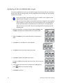
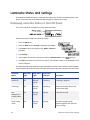
Displaying Laminator Status on the LCD Panel . . . . . . . . . . . . . . . . . . . . . . . . . . . . . . . . . .
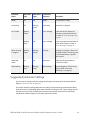
Suggested Laminator Settings . . . . . . . . . . . . . . . . . . . . . . . . . . . . . . . . . . . . . . . . . . . . . . . .
Double-Sided Printing and Double-Sided Lamination . . . . . . . . . . . . . . . . . . . . . . . . .
Single-Sided Printing and Bottom-Side Lamination . . . . . . . . . . . . . . . . . . . . . . . . . . . .
68
69
70
70
Chapter 4: Maintaining Your Printer and Laminator. . . . . . . . . . . . . . . . . . . . . . . . . . . . . 71
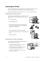
Cleaning the Printer . . . . . . . . . . . . . . . . . . . . . . . . . . . . . . . . . . . . . . . . . . . . . . . . . . . . . . . . . . .
Cleaning the Cleaning Unit . . . . . . . . . . . . . . . . . . . . . . . . . . . . . . . . . . . . . . . . . . . . . . . . . .
Cleaning the Card Load Roller . . . . . . . . . . . . . . . . . . . . . . . . . . . . . . . . . . . . . . . . . . . . . . .
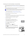
Cleaning the Card Feed Rollers and Heat Roller. . . . . . . . . . . . . . . . . . . . . . . . . . . . . . . . .
Cleaning the Magnetic Head . . . . . . . . . . . . . . . . . . . . . . . . . . . . . . . . . . . . . . . . . . . . . . . .
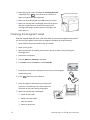
Cleaning the Thermal Head. . . . . . . . . . . . . . . . . . . . . . . . . . . . . . . . . . . . . . . . . . . . . . . . . .
Cleaning the Printer Fan Filter . . . . . . . . . . . . . . . . . . . . . . . . . . . . . . . . . . . . . . . . . . . . . . . .
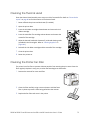
Cleaning the Laminator . . . . . . . . . . . . . . . . . . . . . . . . . . . . . . . . . . . . . . . . . . . . . . . . . . . . . . . .
Cleaning the Card Feed Rollers and Heat Roller. . . . . . . . . . . . . . . . . . . . . . . . . . . . . . . . .
Cleaning the Internal Components . . . . . . . . . . . . . . . . . . . . . . . . . . . . . . . . . . . . . . . . . . .
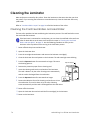
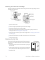
Cleaning the Laminator Cartridge . . . . . . . . . . . . . . . . . . . . . . . . . . . . . . . . . . . . . . . . . . . .
Cleaning the Fan Filter . . . . . . . . . . . . . . . . . . . . . . . . . . . . . . . . . . . . . . . . . . . . . . . . . . . . . .
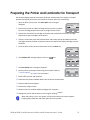
Preparing the Printer and Laminator for Transport . . . . . . . . . . . . . . . . . . . . . . . . . . . . . . . . . . .
72
72
72
73
74
75
75
76
76
77
78
78
79
Chapter 5: Magnetic Stripe Encoding . . . . . . . . . . . . . . . . . . . . . . . . . . . . . . . . . . . . . . . . 81
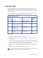
Inline Encoding . . . . . . . . . . . . . . . . . . . . . . . . . . . . . . . . . . . . . . . . . . . . . . . . . . . . . . . . . . . . . . . 82
Character Code Table . . . . . . . . . . . . . . . . . . . . . . . . . . . . . . . . . . . . . . . . . . . . . . . . . . . . . . . . . 83
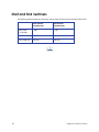
Start and End Sentinels . . . . . . . . . . . . . . . . . . . . . . . . . . . . . . . . . . . . . . . . . . . . . . . . . . . . . . . . . 84
Chapter 6: Error Recovery and Messages. . . . . . . . . . . . . . . . . . . . . . . . . . . . . . . . . . . . . 85
Printer Roller Layout . . . . . . . . . . . . . . . . . . . . . . . . . . . . . . . . . . . . . . . . . . . . . . . . . . . . . . . . . . .
Recovering from Printer Errors . . . . . . . . . . . . . . . . . . . . . . . . . . . . . . . . . . . . . . . . . . . . . . . . . . .
Clearing a Hopper Jam . . . . . . . . . . . . . . . . . . . . . . . . . . . . . . . . . . . . . . . . . . . . . . . . . . . . .
Clearing a Transfer Jam . . . . . . . . . . . . . . . . . . . . . . . . . . . . . . . . . . . . . . . . . . . . . . . . . . . . .
Clearing a Turnover Jam . . . . . . . . . . . . . . . . . . . . . . . . . . . . . . . . . . . . . . . . . . . . . . . . . . . .
Clearing a Retransfer Section Jam . . . . . . . . . . . . . . . . . . . . . . . . . . . . . . . . . . . . . . . . . . . .
Mending a Broken Ink Ribbon or Retransfer Film . . . . . . . . . . . . . . . . . . . . . . . . . . . . . . . . .
Laminator Roller Layout . . . . . . . . . . . . . . . . . . . . . . . . . . . . . . . . . . . . . . . . . . . . . . . . . . . . . . . .
Recovering from Laminator Errors . . . . . . . . . . . . . . . . . . . . . . . . . . . . . . . . . . . . . . . . . . . . . . . .
Clearing a Card Jam . . . . . . . . . . . . . . . . . . . . . . . . . . . . . . . . . . . . . . . . . . . . . . . . . . . . . . .
Adjusting the Patch Position. . . . . . . . . . . . . . . . . . . . . . . . . . . . . . . . . . . . . . . . . . . . . . . . . .
Changing the Front-to-Back Position . . . . . . . . . . . . . . . . . . . . . . . . . . . . . . . . . . . . . . .
Changing the Left-to-Right Position . . . . . . . . . . . . . . . . . . . . . . . . . . . . . . . . . . . . . . . .
Correcting Card Warping. . . . . . . . . . . . . . . . . . . . . . . . . . . . . . . . . . . . . . . . . . . . . . . . . . . .
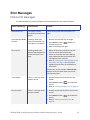
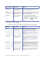
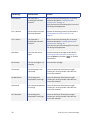
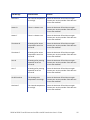
Error Messages . . . . . . . . . . . . . . . . . . . . . . . . . . . . . . . . . . . . . . . . . . . . . . . . . . . . . . . . . . . . . . .
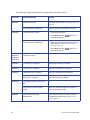
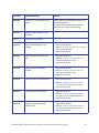
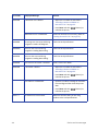
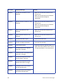
Printer LCD Messages . . . . . . . . . . . . . . . . . . . . . . . . . . . . . . . . . . . . . . . . . . . . . . . . . . . . . . .
Laminator LCD Messages . . . . . . . . . . . . . . . . . . . . . . . . . . . . . . . . . . . . . . . . . . . . . . . . . . . .
86
86
86
87
88
89
90
91
91
91
93
93
94
94
95
95
99
Chapter 7: Supplies . . . . . . . . . . . . . . . . . . . . . . . . . . . . . . . . . . . . . . . . . . . . . . . . . . . . . . 105
ix
Ink Ribbon, Retransfer Film, and Laminator Material. . . . . . . . . . . . . . . . . . . . . . . . . . . . . 106
Cards. . . . . . . . . . . . . . . . . . . . . . . . . . . . . . . . . . . . . . . . . . . . . . . . . . . . . . . . . . . . . . . . . . . . 107
Cleaning Supplies . . . . . . . . . . . . . . . . . . . . . . . . . . . . . . . . . . . . . . . . . . . . . . . . . . . . . . . . . 109
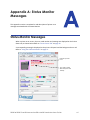
Appendix A: Status Monitor Messages . . . . . . . . . . . . . . . . . . . . . . . . . . . . . . . . . . . . . . . . . . . . . A-1
Status Monitor Messages . . . . . . . . . . . . . . . . . . . . . . . . . . . . . . . . . . . . . . . . . . . . . . . . . . . . . . A-1
Appendix B: Site Requirements and Specifications . . . . . . . . . . . . . . . . . . . . . . . . . . . . . . . . . . .
Site and Usage Guidelines. . . . . . . . . . . . . . . . . . . . . . . . . . . . . . . . . . . . . . . . . . . . . . . . . . . . .
Operating Environment . . . . . . . . . . . . . . . . . . . . . . . . . . . . . . . . . . . . . . . . . . . . . . . . . . . .
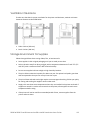
Ventilation Clearance . . . . . . . . . . . . . . . . . . . . . . . . . . . . . . . . . . . . . . . . . . . . . . . . . . . . .
Storage Environment for Supplies . . . . . . . . . . . . . . . . . . . . . . . . . . . . . . . . . . . . . . . . . . . .
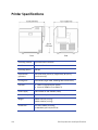
Printer Specifications . . . . . . . . . . . . . . . . . . . . . . . . . . . . . . . . . . . . . . . . . . . . . . . . . . . . . . . . .
Operating Environment Conditions. . . . . . . . . . . . . . . . . . . . . . . . . . . . . . . . . . . . . . . . . . .
Storage Environment Conditions . . . . . . . . . . . . . . . . . . . . . . . . . . . . . . . . . . . . . . . . . . . . .
Laminator Specifications . . . . . . . . . . . . . . . . . . . . . . . . . . . . . . . . . . . . . . . . . . . . . . . . . . . . . .
Operating Environment Conditions. . . . . . . . . . . . . . . . . . . . . . . . . . . . . . . . . . . . . . . . . . .
Storage Environment Conditions . . . . . . . . . . . . . . . . . . . . . . . . . . . . . . . . . . . . . . . . . . . . .
x
B-1
B-2
B-2
B-3
B-3
B-4
B-5
B-5
B-5
B-6
B-6
Chapter 1: Introduction
This chapter contains information about this User’s Guide. It also provides an introduction to the SR200 & SR300 card printers and optional LM200 & LM300 laminators.
About This Manual
This manual provides detailed instructions for operating the SR200 & SR300 card printers and the optional LM200 & LM300 card laminators.
Chapter 1: "Introduction”—Provides basic information about the printer and laminator, including drawings and parts identification.
Chapter 2: "Using the Printer and Laminator”—Provides instructions for using the card printer and laminator to create cards.
Chapter 3: "Printer and Laminator Settings”—Provides instructions for viewing and changing printer settings, including printing preferences and printer properties, as well as laminator settings.
Chapter 4: "Maintaining Your Printer and Laminator”—Contains procedures for cleaning, maintaining, and transporting the card printer and laminator.
Chapter 5: "Magnetic Stripe Encoding”—Contains information about using the card printer to encode magnetic stripe information on cards.
Chapter 6: "Error Recovery and Messages”—Contains procedures for clearing card jams, mending broken ribbons, adjusting laminator patch position, and correcting card warping.
Chapter 7: "Supplies”—Specifies supplies needed for the card printer and laminator. Ordering information (including part numbers, where applicable) is provided for ink ribbons, retransfer film, laminator material, cards, and cleaning supplies.
Related Documentation
Refer to the Datacard SR200 & SR300 Card Printers and LM200 & LM300 Laminators Installation Guide for information about installing and setting up the printer and laminator.
Refer to the Datacard SR200 & SR300 Plug‐in User’s Guide for information about using the card printer with Datacard ID software applications. The manual includes instructions for creating magnetic stripe encoding configurations.
SR200 & SR300 Card Printers and LM200 & LM300 Laminators User’s Guide
1
Whom to Call for Assistance
If you work with a Datacard‐authorized dealer, distributor, or value‐added reseller, contact them for assistance. A value‐added reseller provides the SR200 & SR300 card printers and LM200 & LM300 laminators as part of an overall system.
If any contents of the box are missing, contact your Datacard‐authorized dealer, distributor, or reseller. If you purchased your printer directly from Datacard, contact the Datacard Customer Care Center in your region:
Americas
+1 800.328.3996 or 952.988.2316
Europe, Middle East, and Africa
+44 1489555627
Asia Pacific
+852 2821 0121
Make sure that you have the printer serial number, located on the back of the printer, and optional laminator serial number, when you call.
About the Card Printers
The SR200 & SR300 card printers use retransfer printing technology to produce high‐quality, edge‐to‐edge printing on a variety of PVC and non‐PVC card surfaces, including contact and contactless smart cards.
The retransfer printing process uses two ribbon types—a color ink ribbon and a retransfer film. The ink ribbon is available in YMCK (yellow, magenta, cyan, and black) or YMCKK format. First, the printer uses these colors to print images on the retransfer film. Then the heat roller transfers the resulting image onto a card.
An ink ribbon with a peel‐off (PO) panel is available to remove retransfer material from areas of the card containing a magnetic stripe, hologram, or smart card chip. The printer can also use a YMCK ribbon with a UV retransfer panel.
The SR200 printer can print on one side of a card and the SR300 printer can print on one or both sides of the card. The SR300 printer can also be equipped with optional magnetic stripe and smart card capabilities.
The SR300 printer has the ability to apply two layers of retransfer material (InTM film) on either side or on both sides of a card, for added durability. (Refer to “Applying a Second Retransfer Layer” on page 66.)
2
Introduction
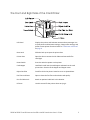
The Front and Right Side of the Card Printer
LCD Panel
Displays the printer and laminator status and any messages. Use to view printer and laminator settings, change some settings, and perform some printer functions. Refer to “Card Printer LCD Panel” on page 6.
Door Latch
Slide the latch up to open the printer door.
Printer Door
Open the door to access the ink ribbon and retransfer film cartridges.
Power Switch
Press the switch to power on the printer.
Card Hopper
Load blank cards into the card hopper and attach to the card printer here. Consists of the hopper and hopper cover.
Reject Card Slot
Cards for which the printer issued an error are ejected here.
Fan Filter and Cover
Open to clean the fan filter and maintain card quality.
Port for Cable Lock
Attach an optional cable lock in this location.
Lift Area
Use this area to lift the printer when carrying it.
SR200 & SR300 Card Printers and LM200 & LM300 Laminators User’s Guide
3
The Back of the Card Printer
4
Product Label
Indicates the printer’s serial number model and agency information.
USB Port
USB 2.0 printer port. Use it to connect the printer to a PC, or use it as a network hub. Connect a USB data cable or a USB smart card cable here, if used.
Ethernet Port
Connect a network data cable here, if used.
Option Label
Indicates the options installed in the printer. For example, the following label is for a printer that has Duplex, Bend Remedy, and Magnetic Encoder options:
Cable Guides
Secure the data cable here to prevent damaging it.
Power Receptacle
Plug in the power cord here.
Introduction
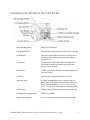
The Inside and Left Side of the Card Printer
Film Cartridge (Green)
Holds the retransfer film.
Film Release Button
Press to release and remove the retransfer film cartridge.
Card Out Slot
After cards are printed, they exit here. If a laminator is installed, printed cards exit the printer and enter the laminator here.
Card Stacker
If no laminator is used, attach the card stacker to the card stacker brackets. As cards exit the printer, they collect in the card stacker.
Infrared Port
Sends or receives data via infrared communication to the laminator, if used.
Lift Area Use this area to lift the printer when carrying it.
Jog Dials (Home)
Use these removable dials when clearing a card jam. Return them to the home locations after use. Refer to the procedures described in “Recovering from Printer Errors” on page 86 for instructions on using the jog dials.
Cleaning Unit
Removes dust or debris from the cards before printing.
Ink Ribbon Cartridge (Orange)
Holds the ink ribbon.
Ribbon Release Button
Press to release and remove the ink ribbon cartridge.
SR200 & SR300 Card Printers and LM200 & LM300 Laminators User’s Guide
5
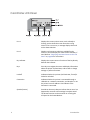
Card Printer LCD Panel
6
Line 1
Displays the current printer status, such as Ready or Printing. It also shows the menu name when using menus. If an error occurs, a message displays here and on the Status Monitor.
Line 2
Displays card counts or selections available for the menus. It can also display the status of the laminator, if used. Refer to “Displaying Laminator Status on the LCD Panel” on page 68 for instructions.
Key Indicator
Displays the current name or function of the key directly beneath the indicator.
Keys
Press keys to navigate the menu and display information about the printer and laminator, and to view or change settings or perform functions.
Locked?
Indicates whether the printer (and laminator, if used) is locked or unlocked.
Connection
Indicates whether the printer is connected through a USB cable or a network connection, and whether or not the printer has an IP address. Also indicates if the laminator is connected.
Speaker (buzzer)
Provides an electronic beep to indicate that an error has happened or to confirm that settings have been saved. The buzzer function can be turned on or off using the LCD panel or the Status Monitor.
Introduction
About the Laminators
The LM200 & LM300 card laminators are optional laminating modules that work with the SR200 & SR300 printers to add topcoat or patch material to printed cards. Holographic laminating material is available for added security and tamper resistance. A printed card can be laminated manually by inserting it into the laminator, or automatically by transferring the card directly from the printer to the laminator.
The LM200 laminator can laminate on one side of a card and the LM300 laminator can laminate on one or both sides of the card. The LM300 selects the side(s) of the card to be laminated by the presence of one or both film cartridges:
To laminate on the top side of the card, load the top‐side cartridge.
To laminate on the bottom side of the card, load the bottom‐side cartridge.
To laminate on both sides of the card, load both cartridges.
Messages and other information about the laminator are displayed on the printer LCD panel, and on the PC (with the Status Monitor).
Datacard recommends that the LM300 laminator be used only with the SR300 printer.
The Front and Rear of the Laminator
OPTION
INLET
Operator Panel
Includes the red and blue status indicator lights and the operator button. Refer to “Laminator Operator Panel” on page 10.
Door Latch
Slide the latch up to open the laminator door.
Laminator Door
Open the door to access the laminator cartridges.
SR200 & SR300 Card Printers and LM200 & LM300 Laminators User’s Guide
7
Power Switch
Press the switch to power on the laminator.
Exhaust Fan
Discharges heat from inside the laminator.
Intake Fan
Draws air into the laminator for internal cooling.
Port for Cable Lock
Attach an optional cable lock in this location.
Power Receptacle
Plug in the power cord here.
The Left and Right Sides of the Laminator
8
Card Outlet
Cards exit the laminator here.
Card Stacker Attachment Slots
Attach the card stacker here. As cards exit the laminator, they collect in the card stacker.
Filter Cover
Remove to access the air intake filter.
Lift Area
Use this area to lift the laminator when carrying it.
Card Inlet
Printed cards enter the laminator here.
Infrared Port
Sends or receives data via infrared communication to the card printer.
Introduction
The Inside of the Laminator
Cartridge Release Button
Press the button to remove the bottom‐side laminate film cartridge.
Bottom‐Side Film Cartridge (Orange)
Holds the laminate film for the bottom side of the card. (LM300 only. A removable cover is located here on the LM200.)
Jog Dial Insertion Slot
Attach the jog dial here to clear a card jam. Refer to “Clearing a Card Jam” on page 91 for instructions.
Top‐Side Film Cartridge (Green)
Holds the laminate film for the top side of the card.
Cartridge Release Button
Press the button to remove the top‐side laminate film cartridge.
Jog Dial (Home)
Use this removable dial when clearing a card jam. Return it to the home location after use. Refer to the procedure described in “Recovering from Laminator Errors” on page 91 for instructions on using the jog dial.
SR200 & SR300 Card Printers and LM200 & LM300 Laminators User’s Guide
9
Laminator Operator Panel
The status of the laminator is displayed on the card printer’s LCD panel and on the Status Monitor of the PC connected to the card printer. The laminator operator panel has two status lights and one operator button, shown below:
10
Red Status Light
A blinking or steady red light indicates a laminator error.
Blue Status Light
A blinking or steady blue light indicates that the laminator is functioning normally.
Operator Button
Press this button after loading a laminator film cartridge, to reset the laminator settings.
When no film cartridge is loaded, press the operator button for two seconds or longer to start the cleaning operation. Refer to “Cleaning the Card Feed Rollers and Heat Roller” on page 76 for cleaning instructions.
Introduction
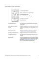
Chapter 2: Using the Printer
and Laminator
This chapter describes how to perform basic tasks required to operate the
SR200 & SR300 card printers and LM200 & LM300 laminators.
This chapter describes how to:
Load supplies
Loading Cards on page 12
Loading an Ink Ribbon on page 15
Loading Retransfer Film on page 16
Loading Top‐Side Laminate Film on page 17
Loading Bottom‐Side Laminate Film on page 18
Power on the laminator and printer
Checking the PC Connection on page 19
Checking the Laminator Connection on page 20
Powering On the Laminator on page 20
Powering On the Printer on page 21
Initializing the Ink Ribbon and Retransfer Film on page 22
Print cards
Printing Cards Using ID Software on page 23
Printing Cards From a PC Application on page 23
SR200 & SR300 Card Printers and LM200 & LM300 Laminators User’s Guide
11
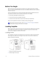
Before You Begin
Make sure that the printer and laminator (if used) are set up and the printer driver installed. Refer to the Datacard SR200 & SR300 Card Printers and LM200 & LM300 Laminators Installation Guide for instructions.
Create the card design(s) to use, and test each design before beginning production. Be sure to use production card stock, and test all data and all processes. For example:
Encode and read magnetic stripe data, if used.
Print and verify the colors and quality of printing.
Laminate test cards and make sure that the results meet your requirements.
Ask your service provider for assistance, if needed, to make your design work.
If the printer uses the security lock, refer to “Security Lock Tab” on page 49. Unlock the printer before starting any of the tasks in this chapter.
Loading Supplies
Before using the printer, make sure that the correct cards have been loaded into the card hopper, that ink ribbon and retransfer film cartridges are installed in the printer, and that (if used) laminate film cartridge(s) are loaded in the laminator.
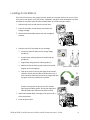
Loading Cards
The card hopper can hold up to 100, 0.030 inch (0.75 mm) cards. The cards are held in position with a hopper cover. Make sure that magnetic stripe cards or smart cards are loaded in the proper orientation for processing.
1. Slide the card hopper latch open (1).
2. Slide the hopper cover up (2).
12
Using the Printer and Laminator
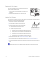
3. Insert cards (3).
Refer to the illustrations for the correct card orientation:
For SR200 (single‐side) printers, position the top of landscape‐
oriented cards away from the printer with the front of the card facing down.
For SR300 (duplex) printers:
Load ISO‐1 magnetic stripe cards with the stripe up and toward the printer.
For most applications, load contact chip cards with the chip down and toward the back of the printer.
For custom applications, the card load orientation may be different.
4. Slide the hopper cover over the cards (4).
5. Slide the card hopper latch closed (5).
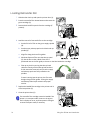
Removing the Card Hopper and Cards
The card hopper can be removed from the printer for secure storage, to adjust card thickness, or for cleaning.
1. Slide the card hopper latch closed (1).
2. Lift the hopper up (2). The hopper cover and hopper are locked together and both are removed.
SR200 & SR300 Card Printers and LM200 & LM300 Laminators User’s Guide
13
Replacing the Card Hopper
If the entire card hopper has been removed from the printer, reinstall it before using the printer.
1
2
1. Insert the hooks on the card hopper into the slots in the receptacle.
2. Slide the card hopper down until it clicks into place.
Adjusting Card Thickness
From the factory, the printer is set to use cards 0.030 inch (0.75 mm) thick. Follow these steps to set the printer to use cards of a different thickness.
1. Remove the card hopper, as described above.
2. Turn the hopper so that the silver dial faces you.
3. Use a pointed item such as a pen to slide the dial:
Counterclockwise to print thinner cards.
Clockwise to print thicker cards.
A setting of 1.0 mm corresponds to cards 0.040 inch thick.
A setting of 0.75 mm corresponds to cards 0.030 inch thick.
A setting of 0.5 mm corresponds to cards 0.020 inch thick.
A setting of 0.25 mm corresponds to cards 0.010 inch thick.
4. Replace the card hopper. (See “Replacing the Card Hopper” above.)
5. Set the card thickness on the Status Monitor. Refer to “Media Setting Tab” on page 44.
6. Test the new setting with several cards to make sure that the printer picks only one card at a time.
Contact your dealer or service provider before using 0.010 inch (0.25 mm) thick cards.
14
Using the Printer and Laminator
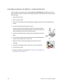
Loading an Ink Ribbon
If this is the first time you are using the printer, power on the printer until an ink error or a film error occurs, then power it off. (The printer is shipped in transport mode, which does not allow ink ribbon or retransfer material to be installed. Power on cancels transport mode.)
1. Slide the door latch up and open the printer door.
2. Press the ink ribbon release button and remove the orange cartridge.
1
3. Remove both used ribbon spools from the cartridge (if present).
2
4. Load the new roll of ink ribbon on the cartridge:
a. Put the full spool of ribbon on the orange supply spindle (A).
b. Put the empty take‐up spool on the black take‐up spindle (B).
c. Align ribbon along the three ribbon guides (C).
d. Make sure that the ribbon panels match the colored diagram in the cartridge (D).
e. Take up any slack by turning the supply knob counter‐
clockwise. Gently pull the take‐up knob and turn (E). If slack cannot be removed, verify that the supply and take‐
up spools are firmly seated on the spindles. To ease inserting into the printer, the film must be tight along the ribbon guides. Turning the supply and take‐up knobs helps maintain the proper tension.
E
6
5. Replace the loaded ribbon cartridge in the printer until it clicks into position.
6. Close the printer door.
SR200 & SR300 Card Printers and LM200 & LM300 Laminators User’s Guide
5
15
Loading Retransfer Film
1. Slide the door latch up and open the printer door (1).
2. Press the retransfer film release button and remove the green cartridge (2).
1
3. Remove both used film spools from the cartridge (if present).
2
4. Load the new roll of retransfer film on the cartridge:
a. Put the full roll of film on the green supply spindle (A).
b. Put the empty take‐up spool on the black take‐up spindle (B).
c. Align film along the three film guides.
d. Wind two frames of film onto the take‐up spool (D). Set the film so that a black frame line is positioned next to the film guide, as shown on the label inside the cartridge.
e. Take up any slack by turning the take‐up knob clockwise. Gently pull the take‐up knob and turn. If slack cannot be removed, verify that the supply and take‐up spools are firmly seated on the spindles.
E
To ease inserting into the printer, the film must be tight along the film guides. Turning the supply and take‐up knobs helps maintain the proper tension.
5. Replace the loaded film cartridge in the printer until it clicks into position (5).
6
6. Close the printer door (6).
The retransfer film cartridge cannot be loaded if the printer is in transport mode. Power on the printer until it displays an error, and then power it off again to cancel transport mode, if necessary.
16
5
Using the Printer and Laminator
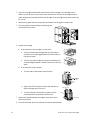
Loading Top-Side Laminate Film
1. Open the laminator door by pulling the top of the door toward you.
2. Remove the top‐side film cartridge:
Press the laminator cartridge release button and remove the laminator cartridge carefully. The laminate material must be tight when removing the cartridge.
3. Remove the used material (if present).
Be sure to save the empty supply spool. (Do not throw it away.) Use the empty spool as the take‐up spool in step 4 of this procedure.
4. Place the new roll of material next to the empty take‐up spool on a clean surface.
5. Remove the label from the laminate material and use it to secure the free end of the material to the empty take‐up spool, making sure that the edges are even.
6. Load the new roll of material on the cartridge:
a. Put the full roll of material on the supply spindle.
b. Put the empty take‐up spool on the take‐up spindle.
c. Align the material along the four metal guides as shown on the cartridge label.
d. Wind two or three rotations of film onto the take‐up spool. Take up slack between the spools by turning the supply knob clockwise. If slack cannot be removed, verify that the supply and take‐up spools are firmly seated on the spindles.
7. Replace the loaded laminator cartridge in the laminator until it clicks into position.
8. Close the laminator door.
9. If the loading status of the cartridge is changed when changing the side to be laminated, the laminator does not initialize when the laminator door is closed. Press the Operator button to initialize the laminator.
SR200 & SR300 Card Printers and LM200 & LM300 Laminators User’s Guide
Operator Button
17
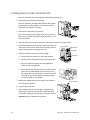
Loading Bottom-Side Laminate Film
1. Open the laminator door by pulling the top of the door toward you.
2. Remove the bottom‐side film cartridge:
Press the laminator cartridge release button and remove the laminator cartridge carefully. The material must be tight when removing the cartridge.
3. Remove the used material (if present).
Be sure to save the empty supply spool. (Do not throw it away.) Use the empty spool as the take‐up spool in step 4, of this procedure.
4. Place the new roll of material next to the empty take‐up spool on a clean surface.
5. Remove the label from the laminate material and use it to secure the free end of the material to the empty take‐up spool, making sure that the edges are even.
Take-up Spool
Metal Guides
Guide Shaft
6. Load the new roll of material on the cartridge:
a. Put the full roll of material on the supply spindle.
Supply Roll
b. Put the empty take‐up spool on the take‐up spindle.
c. Align the material along the four metal guides as shown on the cartridge label.
d. Wind two or three rotations of film onto the take‐up spool. Take up slack between the spools by turning the supply knob counterclockwise. If slack cannot be removed, verify that the supply and take‐up spools are firmly seated on the spindles.
7. Replace the loaded laminator cartridge in the laminator until it clicks into position.
Operator Button
8. Close the laminator door.
9. If the loading status of the cartridge is changed when changing the side to be laminated, the laminator does not initialize when the laminator door is closed. Press the Operator button to initialize the laminator.
18
Using the Printer and Laminator
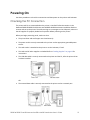
Powering On
Use these procedures to check the connections and then power on the printer and laminator.
Checking the PC Connection
The printer and PC are connected when the printer is installed. Follow instructions in the Datacard SR200 & SR300 Card Printers and LM200 & LM300 Laminators Installation Guide to connect and set up the printer. To avoid receiving error messages on the LCD panel, make sure that all supplies are properly loaded and in position before powering on the printer.
Before you begin processing cards, make sure that:
The printer door and card hopper are closed securely.
The power cord is securely connected to the printer and an appropriate grounded power source.
The card stacker is attached to the printer or to the laminator, if used.
The cards and all other supplies are loaded. Refer to “Loading Supplies” on page 12 for instructions.
The USB data cable is securely connected to the printer and the PC, after the printer driver has been installed.
OR
The network data cable is securely connected to the printer and to a network port.
SR200 & SR300 Card Printers and LM200 & LM300 Laminators User’s Guide
19
Checking the Laminator Connection
When using the LM200 or LM300 laminator, make sure that:
The printer and laminator are aligned at the infrared ports, using the joining plate.
The power cord is securely connected to the laminator and an appropriate grounded power source.
Supplies are loaded and the laminator door is closed securely.
Powering On the Laminator
When the LM200 or LM300 laminator is used, power on the laminator before powering on the printer.
Blue Status Light
1. Press the laminator power switch.
2. Make sure that the laminator is ready before proceeding to power on the printer:
20
The printer LCD panel displays Initializing and the blue status indicator light blinks.
Preheating displays on the printer LCD panel for approximately four minutes while the heat roller warms to operating temperature.
The laminator material initalizes automatically.
The printer LCD panel displays Ready and the blue status light is lit when the laminator is ready to process cards.
Power Switch
Using the Printer and Laminator
Powering On the Printer
1. Press the power switch.
2. Make sure that the printer powers on and begins initializing. The LCD panel displays Initializing while the printer checks and positions the ink ribbon and retransfer film.
During power on, the printer’s LCD panel displays the following status messages:
When operation checks are complete, Preheating is displayed on the LCD panel for approximately two minutes while the retransfer roller (and optional bend remedy roller) warm to their operating temperatures.
Power Switch
When ready to print, the LCD panel displays Ready.
3. The first time you print cards, initialize the ink ribbon and retransfer film. Refer to “Initializing the Ink Ribbon and Retransfer Film” on page 22.
The printer can require several minutes between power on and the Ready status.
SR200 & SR300 Card Printers and LM200 & LM300 Laminators User’s Guide
21
Initializing the Ink Ribbon and Retransfer Film
Cards can be printed when the LCD panel displays Ready. Follow these steps to initialize the ink ribbon and retransfer film when cartridges are installed or when Sleeping displays on the LCD.
1. Press the Reset key on the LCD panel. The LCD display reads Initialize OK?
2. Press (Return) if you want to initialize the printer without winding the ribbon and retransfer film.
OR
Use the Next key to display 2'nd Panel, OK? or Next Panel, OK? if you want to wind the ribbon and transfer film before printing:
Press when 2’nd panel, OK? is displayed. The printer winds the ribbon and film two panel sets.
Press when Next Panel, OK? is displayed. The printer winds the ribbon and film one panel set.
Printing Cards
Print cards after installing the printer and printer driver, and after setting up your card design. Refer to “Before You Begin” on page 12.
Card designs can be printed from ID software, which handles the types of information used on cards. If you do not have ID software, you can use a different PC application to design the cards. However, most PC applications do not support magnetic stripe encoding or smart card programming. With any application, test the card design to verify the results.
The printer LCD panel displays the following sequence while a card is being printed:
Tips for Success
22
To restore the printer when it is in sleep mode, press Reset and then LCD panel.
on the printer
Handle unprinted cards by the edges to preserve print quality. Do not touch the print surface with your hands. Use the supplied white gloves to handle cards.
Refer to Chapter 5: "Magnetic Stripe Encoding” for information about encoding magnetic stripe data on cards.
Using the Printer and Laminator
Printing Cards Using ID Software
1. Follow the instructions for your ID software to capture, format, and save the data for the card.
2. In the software, send cards to the printer. (Typically, you use the Print button.)
The printer driver receives data for each card, prepares the card for printing, and sends each card to the printer.
Each printed card exits the printer and is deposited into the card stacker or goes directly into the laminator.
Printing Cards From a PC Application
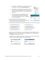
1. Use the page setup feature in the software application to set the following:
Set paper or page size to CR80 card or 2.125 inch x 3.375 inch.
Set the orientation for the card design—either portrait or landscape.
Set margins to zero for edge‐to‐edge printing.
2. Format and save the card information.
3. Select the SR‐CP U1 printer from the Print dialog box.
SR‐CP U1 is the default name of the printer when connected with a USB cable. Your printer may have a different name. 4. Click Printer Properties to open the Printing Properties dialog box. Use the Setup, Print, and Encode tabs to set printer properties:
Setup Tab: Set the card orientation, number of copies, and whether to turn the card over after loading.
Print Tab: Set printing on one side or both sides, and rotation. The Print tab contains settings for using the color (YMC) and black (K) panels of the print ribbon. This tab also contains controls for color adjustment, setting up a look‐up table, and specifying the print area for ribbon panels, including peel‐off areas.
Encode Tab: View or change settings for using smart card (IC) and magnetic stripe encoding. You can also specify whether to rotate the card after an encoding step.
SR200 & SR300 Card Printers and LM200 & LM300 Laminators User’s Guide
23
5. When you are finished, click OK to close the Printing Preferences dialog box.
6. Click Print in the Print dialog box to print the card.
For a complete description of settings that can be viewed or changed, refer to “Introduction to Printer and Laminator Settings” on page 26.
24
Using the Printer and Laminator
Chapter 3: Printer and
Laminator Settings
This chapter contains information and procedures for viewing and changing SR200 & SR300 card printer and LM200 & LM300 laminator settings.
This chapter describes:
Printing Properties on page 26
Printing Preferences on page 27
Using the Status Monitor on page 38
Using the LCD Panel Menus on page 51
Connection and Lock Symbols on page 52
Key Functions on page 52
LCD Panel Menu Structure on page 54
Using a Printer Security Key on page 63
Laminator Status and Settings on page 68
Displaying Laminator Status on the LCD Panel on page 68
Suggested Laminator Settings on page 69
SR200 & SR300 Card Printers and LM200 & LM300 Laminators User’s Guide
25
Introduction to Printer and Laminator Settings
Three main tools allow you to create or modify settings that determine how the printer performs and how cards are printed and laminated:
Printer Driver: Settings made on the Printing Properties dialog box or the Printing Preferences dialog box are written to the printer driver. These dialog boxes allow you to specify many of the settings that affect how your SR200 or SR300 card printers function.
Status Monitor: Settings made on the Status Monitor are written to the PC. In cases where a setting can be made through either the printer driver or on the Status Monitor, the printer driver takes precedent over the Status Monitor and changes made to encoding in the driver are not displayed in the Status Monitor or on the LCD panel.
LCD Panel: The printer’s LCD panel allows you to view many current printer and laminator settings as read‐only. To change those settings, use the Status Monitor, or the Printing Preferences or Printing Properties dialog box. Some printer functions can be performed, and some settings entered, using the LCD panel.
Printing Properties
The Printing Properties dialog box options are set up when the printer is installed, or by your system administrator.
1. Select Start from the Windows task bar.
2. Open your PC’s Printers or Devices and Printers window, following the steps for your operating system.
3. Locate the Datacard card printer icon.
The printer driver must be installed for the printer icon to be present.
SR‐CP U1 is the default name of the printer (or SR‐CP LAN, if a network printer). The name of your printer might be different.
4. Right‐click the printer icon and select Printer Properties. The Properties dialog box opens.
5. Use the tabs to set up Sharing, Ports, Color Management, Security, and Advanced options.
6. Click OK to save and close, or click Cancel to close without saving changes.
26
Printer and Laminator Settings
Printing Preferences
The Printing Preferences dialog box contains the Setup, Print, Encode, Laminate, Configuration, and Version tabs. Use the settings in these tabs to customize your card printer and laminator operation.
To view or change Printing Preferences:
1. Select Start from the Windows task bar. 2. Open your PC’s Printers or Devices and Printers window, following the steps for your operating system.
3. Locate the Datacard card printer icon.
The printer driver must be installed for the printer icon to be present.
The default name of the SR200 or SR300 card printer is SR‐CP U1 (or SR‐CP LAN, if a network printer). The name of your printer might be different.
4. Right‐click the printer icon and select Printing Preferences from the pop‐up menu. The Printing Preferences dialog box opens.
5. Click to select the desired tabs and make any desired changes, as described below.
6. Click OK or Apply to save the settings, or Cancel to close the Printing Preferences window without saving any changes.
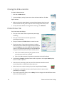
Setup Tab
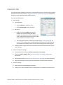
Use the Setup tab to specify the card orientation and number of copies (your ID software might specify these settings, which override the Setup tab). You can also specify whether the printer will turn over the card after it is picked, for printers with two‐sided printing capability.
The Setup tab includes the Save and Load buttons. Refer to “Saving Settings” on page 28 and “Loading Settings” on page 28 to save and load printer settings for use with additional SR200 & SR300 printers.
SR200 & SR300 Card Printers and LM200 & LM300 Laminators User’s Guide
27
Saving Settings
If your location uses several printers that need the same settings, you can set up one printer and save the settings to a .dat file. (Settings that can be shared are saved to the file. Settings include Printer, Preferences, and Status Monitor settings.)
1. Open Printing Preferences as described on page 27.
2. Use the Printing Preferences tabs to set up the printer to meet the needs of your card design program.
3. Click the Setup tab, then click Save.
A Windows Save As dialog box displays.
4. Save the printer settings file:
a. Select a location to which you have permission to save settings.
b. Type a file name that reflects the program, printer serial number, or other significant information.
c. Select Printer Profile (*.dat) for the file type.
d. Click Save.
Loading Settings
Follow these steps to load a saved .dat file onto an additional card printer (with printer driver installed).
1. Open Printing Preferences, then click the Setup tab.
2. Click Load.
A Windows Open dialog box displays.
3. Locate the .dat file and open it.
4. Click Yes to confirm that you want to load the settings, then click Apply to use the settings.
5. Repeat step 1 to step 4 for additional printers.
28
Printer and Laminator Settings
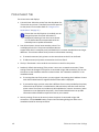
Print Tab
The Print tab contains settings for using the color (YMC) panels, black (K) panels and additional panels of the print ribbon. The tab also has controls for color adjustment, setting up a look up table, setting up page split, and dithering. Refer to“Page Split” on page 32 for more information.
To print text, bar codes, or both, using black (K) ink on a card using an ink ribbon with YMCK panels, select Extraction > Only text.
To print black areas of graphics with K ink ribbon, select Extraction > All.
If you print graphics with black ink, you can set the density of dithering by clicking the Dither button.
If your printer includes a turnover unit for two‐sided printing, you can specify whether to print on both sides of the card. For each side, you can select the ribbon panels to use and whether to rotate the image (your ID software might specify these settings, which override the Print tab). Use ribbon panels such as peel‐off or UV only if the ribbon includes them and your ID software sends data for them. (Sending data for panels that are not present causes errors.)
Use the Printing area settings to block a specific area from printing, such as an area for peel‐off ribbon. Use the UV Ink settings if you use print ribbon with a UV panel. Look Up Table
The look up table adjusts printing by substituting one color for another. It is sent to the printer, where the values are used as the card is printed.
The look up table requires a file with a full set of 256 values (0–255) for each plane, in order, for yellow, magenta, cyan, and black (1024 values). Each field can have a value from 0 through 255. Data must be ASCII numeric values, separated by a comma or line feed.
SR200 & SR300 Card Printers and LM200 & LM300 Laminators User’s Guide
29
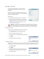
Color Adjustment
Use the Color dialog box to adjust your images before sending them to the printer. The settings affect all parts of a card, including a color logo, color photo, and color backgrounds.
UV Ink
Use the UV Ink dialog box to select how to print the UV ink panel, if used. You can:
Use UV printing on the front of the card, the back of the card, or both.
Extract text of a specific color, which you specify. White (255,255,255) and black (0,0,0) are not allowed.
30
The text is printed using the UV panel with full grayscale intensity (255).
The text is not printed with the color panels.
Print the contents of a bitmap file, which you specify in the File Information area. The bitmap can be:
Monochrome (one bit‐per‐pixel), where white is printed with full intensity (255). If white is the no‐printing color, black is printed with full intensity.
16 colors or 4‐bit color, printed with 256 gradations.
256 colors or 8‐bit color, printed with 256 gradations.
32K colors, or 16‐bit color, printed with 256 gradations. Only the (MSB) GGGBBBBB‐
XRRRRRGG(LSB) format is supported.
24‐bit and 32‐bit color, printed with 256 gradations.
Select a no‐printing color, which is not printed with the UV panel.
This color becomes the unprinted background of the UV plane.
Be careful to select a color not contained in your images—it is extracted by the driver, and color printing can cause a void.
Use a multipage input document to print the YMC (color), black (K), and UV panels in that order. Refer to“Page Split” on page 32 for more information.
Printer and Laminator Settings
Specify the MAC address position. When using the UV panel, the MAC address of the printer is always printed on the card using the UV panel:
Choices are Upper Right (1) and Lower Left. (2), where (3) is the 0,0 point of the card image. The MAC address block is 34 pixels high and 230 pixels long.
Landscape: The upper right location starts at 764,18. The lower‐
left location starts at 42,611.
Portrait: The upper right location starts at 612,743. The lower‐left location starts at 19,42.
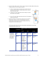
Specify the number of retransfer panels used to print one side of a card (1 Panel, 2 Panels, or Auto). UV and YMCK inks cannot be transferred in the same area on the same retransfer panel, so this setting determines what data will print.
The following table shows the result for data outside the MAC address area and data overlapping the MAC address area:
Printing Data
Printing data that overlaps with the UV ink data outside the MAC address printing area.
Setting for Number of Retransfer Film Panels to Use
1 Panel Auto 2 Panels
None Print in one panel
Print in one panel
Print in two panels
YMC Ink
Print in one panel (The YMC ink is not printed in areas where it overlaps with the UV ink.)
Print in two panels
Print in two panels
K Ink
Print in one panel (The UV ink is not printed in areas where it overlaps with the K ink.)
Print in two panels
Print in two panels
SR200 & SR300 Card Printers and LM200 & LM300 Laminators User’s Guide
31
Printing Data
Setting for Number of Retransfer Film Panels to Use
1 Panel Printing data inside the MAC address area.
Auto None Print in one panel YMC Ink
K Ink
Print in one panel (Does not print using the YMCK ink.)
UV Ink
Prints the MAC address only
2 Panels
Print in two panels
Print in two panels
Print in two panels
Print in two panels
Print in two panels
The printer driver compares printing data for each type of ink to determine whether there are any overlapping pixels. Priority is given to the “Print in 2 panels” setting.
Priority of Data
• The MAC address data is always printed using the UV panel. The area can knock out other printing.
• Image files are processed in the order registered and shown in the File Information area. Newer data
replaces older data if it overlaps.
• Extracted text has higher priority than an image file and prints on top of any image.
• Page Split overrides extracted data and any image files.
Page Split
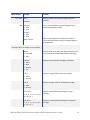
Page Split informs the printer driver that you plan to use a multipage input document: one page for YMC (color), another page for black (K), and (if you use UV ink) an additional page for a UV panel, in that order. You can specify Page Split for black (K) printing and for UV panel printing.
The following example shows a two‐page document with YMC and K printing on one side of the card, and Page Split chosen for K printing on the same side of the card.
32
Printer and Laminator Settings
The following table shows how the Page Split feature can be used for different combinations of YMC, K and UV printing. The Front side and Back side settings on the Print tab must also be set to support printing.
K Ink: Split?
UV Ink: Split?
Page Numbers
1
2
3
4
Front
Back
Front
Back
5
—
—
—
—
YMC
KB
—
—
—
—
YMCK
YMCKB
Yes
—
—
—
YMC
K
YMCKB
—
—
Yes
—
YMCK
UV
YMCKB
Yes
—
Yes
—
YMC
K
UV
—
Yes
—
Yes
YMC
K
YMCKB UVB
Yes
Yes
—
—
YMC
K
YMCB
—
—
Yes
Yes
YMCK
UV
YMCKB UVB
Yes
Yes
Yes
—
YMC
K
UV
YMCB
KB
Yes
Yes
Yes
Yes
YMC
K
UV
YMCB
KB
6
YMCKB
KB
UVB
B
Printed on the back of the card.
SR200 & SR300 Card Printers and LM200 & LM300 Laminators User’s Guide
33
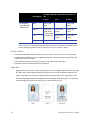
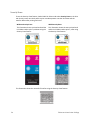
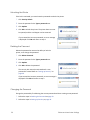
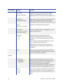
Security Erase
To use the Security Erase feature, load a YMCK ink ribbon and select Security Erase on the Print tab. Security erase uses the K panel to print a random pattern onto the ink ribbon and the transfer ribbon after printing each card.
Without Security Erase
This illustration shows a printed card and the ink ribbon used to print it, without using the Security Erase feature:
With Security Erase
This illustration shows the same printed card and the ink ribbon used to print it, after using the Security Erase feature:
This illustration shows the retransfer film after using the Security Erase feature:
34
Printer and Laminator Settings
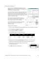
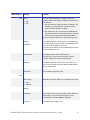
Printing Area Settings
On the Print tab, click Enable the printing area and click Settings to define non‐printing areas of a card design. Also use with peel‐off (YMCK‐PO) ribbon.
You can block YMCK printing areas, but the protective layer from the retransfer material is still applied to the card. To maintain quality, use the peel‐off feature and peel‐off ribbon to remove the retransfer material in magnetic stripe, smart card chip, and hologram areas.
The Printing area dialog box contains settings for x and y starting coordinates, height and width of print area, ink type, card side, and energy settings.
You can add up to three non‐printing areas per side. However, none of the non‐printing areas can overlap each other.
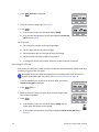
To define a non‐printing area:
1. Enter the x and y coordinates of the start position and the height and width in millimeters.
2. Select 1. Peeloff or 2. YMCK from the Ink list.
3. Select 1. Front or 2. Back from the Side list.
For ISO magnetic stripes, use the following values:
X start
Y start
Width
Height
Ink
Side
0
0
87.46
17.86
1 Peeloff
1. Back
0
0
87.46
21.42
2 YMCK
1. Front
4. Made adjustments to the Peel off ink energy settings (E1, E2, and E3), as needed.
The Peel‐off Ink Energy settings affect the print density or strength of peel‐off.
For best results, use the default settings. The printer driver sets the width of each area.
5. Click Add to add the non‐printing area.
SR200 & SR300 Card Printers and LM200 & LM300 Laminators User’s Guide
35
Printer Settings
On the Print tab, the “Enable printer settings” feature is available for administrator‐level users. Refer to “Configuration Tab” on page 37 for more information about this setting. Click Settings to open the Settings dialog box. The Settings dialog provides a convenient location to manage settings provided on several tabs in the Status Monitor. Refer to“Printer Setting Tab” on page 42, the “Retransfer Tab” on page 43, or the “Bend Remedy Tab” on page 44 for more information about the available settings.
Encode Tab
The Encode tab contains settings for using smart card (IC) and magnetic stripe encoding. (Your ID software might specify these settings, which override the Encode tab.) You can also specify whether to turn over the card after an encoding step.
Only options installed in the printer display in this tab. Refer to Chapter 5: "Magnetic Stripe Encoding” on page 81 for more information about encoding magnetic stripes.
Refer to the Datacard SR200 & SR300 Plug‐in User’s Guide for information on using Datacard ID software applications to encode magnetic stripe onto cards.
Laminate Tab
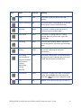
The Laminate tab contains mode settings for the laminator, if one is used. Three modes are available:
36
Default: Operates using the settings defined in the Laminator tab of the Status Monitor.
Pass Through: Does not laminate the card.
Laminate: Laminates the card.
Printer and Laminator Settings
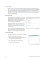
Configuration Tab
The Configuration tab displays the options installed in the printer, if any. The Enable the Settings area is available for administrator‐
level users. Use this option to print a card using settings that are different from those saved in the printer. The changes made using this method are not saved in the printer. After this card is printed, the previous printer settings are restored.
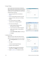
To enable temporary printer settings:
1. Select Start from the Windows task bar. 2. Open your PC’s Printers or Devices and Printers window, following the steps for your operating system.
3. Right click the SR‐CP printer, and select Run as Administrator.
4. Select Properties.
5. In the General tab of the Properties dialog box, select Printing Preferences.
6. Click the Configuration tab.
7. Select the box under Enable the settings.
8. Select the Print tab and click Settings to change settings for the next card to be printed.
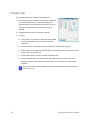
Version Tab
The Version tab shows the build version of the printer driver. Your service provider might ask you for this information. SR200 & SR300 Card Printers and LM200 & LM300 Laminators User’s Guide
37
Using the Status Monitor
During installation, the printer driver and Status Monitor are installed onto the PC. The Status Monitor handles bidirectional communication between the printer and the printer driver. An administrator‐level user can use the Status Monitor to view or change most printer and laminator settings.
Opening the Status Monitor
Tips for Success
Users without administrator permissions can view settings but cannot change them. Start the Status Monitor with administrator permissions if you want to change settings.
The first time you open the Status Monitor on Windows Vista, you must open it as administrator. If you do not, the Status Monitor displays the following message:
If you click Cancel, you can try to open the Status Monitor as an administrator.
If you click OK, Windows Vista displays the error shown:
When you receive the error, uninstall the Status Monitor, restart Windows Vista, and install the Status Monitor again.
To open the Status Monitor window:
1. Begin with the printer powered on and connected to the PC.
2. To start the Status Monitor with administrator permissions, do the following:
Use the desktop icon if you installed it.
OR
38
From the Windows task bar, select Start > Programs > SR Card Printer Status Monitor.
Printer and Laminator Settings
For Windows 7 and WIndows Vista, right‐click the SR Printer Status Monitor icon and select Run As administrator.
For Windows XP and 2000, right‐click the SR Printer Status Monitor icon and select Run As In the Run As dialog box. Enter the name and password for a user name with administrator permissions.
The first time you start the Status Monitor on a PC with the Windows Firewall enabled, a Windows Security Alert dialog box may display. Click Unblock to use the Status Monitor.
3. To start the Status Monitor without administrator permissions, click the icon to open it. A prompt indicates that you cannot change settings. Click OK to continue.
4. The Status Monitor window opens. Use these Status Monitor tabs to view or specify settings:
Printer Status tab (page 40)
Printer Setting tab (page 42)
Retransfer tab (page 43)
Bend Remedy tab (page 44)
Media Setting tab (page 44)
Property tab (page 46)
Laminator tab (page 47)
Printer Select tab (page 48)
Security Lock tab (page 49)
Others tab (page 51)
5. Tabs that allow you to change settings contain a Refresh button and an Update button. Click Refresh to obtain current values from the printer and display them on the Status Monitor. Click Update to send settings to the printer.
A “Would you like to refresh printer setting?” or “Would you like to change printer setting?” dialog box displays. Click OK or Cancel to complete the procedure.
SR200 & SR300 Card Printers and LM200 & LM300 Laminators User’s Guide
39
Closing the Status Monitor
To close the Status Monitor:
1. Click the red Close button.
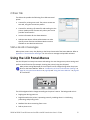
2. A prompt displays, asking if you want to close the Status Monitor. Click Yes.
Tips for Success
When you close the Status Monitor, communication between the printer and driver becomes one way, with the printer driver sending cards to the printer.
To keep the Status Monitor running without viewing it, click Minimize.
Printer Status Tab
The Printer Status tab displays:
40
The type of ink ribbon and the approximate percentage remaining.
The type of retransfer film and the approximate percentage remaining.
The print counter and a Clear button to reset it to zero.
The printer name. If more than one printer is installed, select the printer to work with using the Printer Selection list. Click Update to search for additional SR200 & SR300 printers. The information displayed on the Status Monitor changes automatically when you select another printer:
If the PC is network‐connected, only printers on the same subnet as the PC can be found.
If the PC is USB‐connected, all printers connected to the PC will be found.
Card Quantity: Enough is displayed when cards are present in the hopper. None displays when no cards are present.
If the printer is processing a job, the name of the document and the name of the user displays in the Document Information area.
When the printer requires cleaning, the printer image displays Cleaning:
If a laminator is attached, laminator status displays under the printer status (marked by the rectangle).
The current state of the printer, such as Ready. The icon changes color with different states. Refer to the following table:
Printer and Laminator Settings
Icon
Status
Icon Color
Meaning
Ready
Green
The printer is ready and able to start card
printing.
Printer is not found.
Red
The printer power is not powered on, or the host PC and printer are not connected correctly.
Initializing
Yellow
The printer is initializing. After the printer is initialized, it goes into Ready state.
Offline Mode
Yellow
The printer is in setting mode or it is being cleaned. When the process ends, it goes into Ready state.
Preheating
Yellow
The heat roller is heating. When it reaches the correct temperature, the printer goes into Ready state.
Heating
Yellow
The printer is adjusting the heat roller temperature.
Card Loading
Card Transporting
Contact IC Encoding
Non‐Contact IC Encoding
MG Encoding
Printing
Retransfer
Yellow
The printer is issuing cards. The operating status during card issuing is indicated. When the card is issued, the printer goes into Ready state.
Power Saving
Yellow
The printer is in power save mode. To end power saving, press the Reset key on the printer and then press (Return) to initialize the printer.
Error
Red
Refer to “Status Monitor Messages” on page 51.
SR200 & SR300 Card Printers and LM200 & LM300 Laminators User’s Guide
41
Printer Setting Tab
The Printer Setting tab displays:
Controls for viewing or changing print settings:
YMC Ink Print Level. Sets the print density for color printing. Select from seven gradations from ‐3 (lighter) to +3 (darker).
Resin K Ink Print Level. Sets the K resin ink print density. Select from seven gradations from ‐3 (lighter) to +3 (darker).
UV Ink Print Level. Select from seven gradations from ‐3 (lighter) to +3 (darker).
Peel Off Ink Print Level. Select from seven gradations from ‐3 (lighter) to +3 (darker).
Resin K Ink Print Mode. Sets the K resin ink print quality. If Fine is selected, the print quality improves but the printing speed is slower. Change to Fine if thin lines or small black text is blurred on the cards.
MG Peel Mode. Select MG Stripe for the printer to use peel off ribbon in the magnetic stripe area (if installed).
Standby Mode. Pauses the card after printing and before transferring the card to the laminator.
Back Side Cooling. Select Enable to cool the card when printing on both sides of the card.
Controls for viewing or changing magnetic stripe settings:
Number of Retry. Sets the maximum number of retries when writing or reading magnetic stripe data fails. Default value is 1.
ISO Mode. Sets the power used by the magnetic card encoder. The default is Hi‐Co.
JIS Mode. Sets the power used by the magnetic card encoder. The default is Hi‐Co.
Controls to set power saving capabilities:
Power Saving Interval: Select the interval to wait until power saving takes effect and the printer goes to sleep. Select Off for network operation or select from 5 to 60 minutes for a USB connection. The default is Off.
When the printer goes into power save mode, Sleeping displays on the LCD panel. To cancel power save mode, press Reset and then the (Return) key.
42
HR Control: Select Enable to lower the temperature of the retransfer heat roller when printing is not performed for 30 minutes or longer. When enabled, heat roller Printer and Laminator Settings
temperature drops if the printer goes to sleep. Select Disable to keep the heat roller(s) at operating temperature, even when cards are not being printed.
If a laminator is installed, the HR Control setting also affects the laminator heat roller. The roller(s) return to operating temperature when the next card is printed. The default is Enable.
You can view this setting on the LCD panel (refer to the Heat Roller menu option in the “Using the LCD Panel Menus” on page 51), and on the Laminator tab of the Status Monitor (refer to “Laminator Tab” on page 47).
Others, including:
A control to enable or disable the LCD display buzzer.
A control to set the LCD display contrast.
A control to set the LCD display mode.
A control to change the LCD display counter. Select the type of counter to be displayed on the LCD panel.
For a description of the five types of counter, refer to the Property Tab on page 46.
Retransfer Tab
Use the Retransfer tab to specify how images are moved from the retransfer film onto the cards.
The Retransfer tab displays the:
Front Side matrix and a Back Side matrix for setting the retransfer speed and temperature. Click a square to select the temperature setting.
UV Speed slider for setting the speed of the retransfer heat roller (card front and back) when UV ink is used.
Card Type (read‐only). Use the Media Setting tab (page 44) to specify the card type being used.
Tips for Success
The transfer power to the card gets stronger towards the upper right, but the card becomes more distorted due to the heat.
Changing the retransfer temperature on one card side also affects the temperature on the other side of the card.
The recommended range of values depends on the type of card being used. Use the Media Setting tab to specify the card type with the Media Setting tab. (Refer to page 44 for instructions.)
SR200 & SR300 Card Printers and LM200 & LM300 Laminators User’s Guide
43
Print sample cards to verify settings before using new settings.
Bend Remedy Tab
Single‐sided printing can cause cards to warp, depending on the type of card you use. The printer is available with a bend remedy option.
The Bend Remedy tab is enabled only if the bend remedy option is installed. It displays the:
Matrix for setting the bend remedy speed and temperature. Click a square to select the setting. Or click Disable to prevent bend remedy from being applied.
Card Type (read‐only). Use the Media Setting tab (page 44) to specify the card type being used.
Tips for Success
The Card Type is blank if the bend bemedy option is not installed in the printer.
Bend remedy is effective for single‐side printing. For double‐sided printing, select the Disable option.
If you select Disable and the bend remedy option is installed, the printer goes into Preheat state for about 10 minutes while the roller temperature drops. Wait until the printer status changes to Ready before printing.
If bend remedy is performed, the printed card may have a matte finish, rather than a smooth finish.
Print sample cards to verify results before using the new bend remedy settings.
Media Setting Tab
The Media Setting tab displays the type of ink ribbon in the printer, the lot number of the ribbon, and the number of panel sets included in the ribbon. The printer provides this information and it cannot be changed.
The Media Setting tab also allows you to set the type and thickness of card and the type of retransfer film being used in the printer.
44
Printer and Laminator Settings
If the printer cannot recognize the type of ink ribbon, one of the following reasons is displayed:
Display
Reasons for ink recognition error
Solutions
252: Invalid TAG Data
The data for the ink ribbon is incorrect.
Replace the ink ribbon and try again.
253: Defective TAG
The printer did not recognize the print ribbon data.
Replace the ink ribbon and try again.
254: No TAG
The printer could not read the print ribbon data.
Make sure that the ink ribbon has been loaded correctly. Refer to “Loading an Ink Ribbon” on page 15.
255: Defective
R/W
The printer is defective.
The printer must be repaired.
Use the Media Setting tab to view or change the type and thickness of cards being used:
1. For Material, select PVC, PET‐G, or HR‐PET‐G (0.25 mm).
The recommended values for retransfer speed and temperature depend on the selected card type. (Refer to “Retransfer Tab” on page 43.)
2. For Thickness, select:
Standard for cards 0.75 mm (0.030 inch) thick
Thin for cards 0.25 mm (0.010 inch) thick
Caution: The Thin setting is not recommended for
use with PVC cards.
3. Use Film Type to select the type of retransfer film being used.
Tips for Success
Print sample cards to verify settings before using cards of a different thickness or material type.
Print on one side of thin cards. Do not print on both sides.
Set the input hopper for the card thickness. Refer to “Adjusting Card Thickness” on page 14.
Thin PVC cards are not supported.
SR200 & SR300 Card Printers and LM200 & LM300 Laminators User’s Guide
45
Property Tab
The Property tab displays read‐only information for:
The version of printer firmware, and firmware versions of any installed options such as a laminator. None or ?? means an option is not installed or connected. For smart card, the text shows what is supported, not what is installed.
Configuration information for options installed.
Counters:
Print Counter: The number of cards that have printed correctly. The counter can be reset on the Printer Status tab.
Cleaning Counter: The number of cards printed since the last cleaning card.
Error Counter: The number of cards that were not printed correctly. The counter can be reset on the Printer Status tab.
Printer Total Counter: The total number of cards printed.
Thermal Head Counter: The total number of printed sides for the same head. This counter cannot be reset; however, it automatically resets itself when the printhead is replaced.
You can select which counter displays on the LCD panel using the Printer Setting tab (refer to page 42.)
46
Printer and Laminator Settings
Laminator Tab
The Laminator tab is enabled if a laminator is connected to the printer. Use the settings to adjust lamination for best results. Refer to “Suggested Laminator Settings” on page 69 for examples of settings for single‐sided and double‐sided lamination.
The Laminator tab displays:
Basic Settings:
Laminate Mode:
Select Laminate to laminate a card.
Select Pass Through to skip lamination.
HR Control:
Read‐only. Displays Enable if HR Control is enabled on the Printer Setting tab. When enabled, the temperature of the laminator heat roller is lowered when the printer and laminator are not used for 30 minutes or longer.
This setting works with the card printer setting (refer to “Printer Setting Tab” on page 42). This is always set to On automatically when overlay film is selected. (Put the laminator into standby mode if you will not be printing cards for a long time.)
Cleaning Counter: Displays how many laminations have been performed since the last roller cleaning.
Bottom and Top Side Settings:
Cassette Status field: Displays Cassette is Detected or No Cassette.
Film Type: Patch or Overlay. Refer to“Laminator Material” on page 106 for more information.
Patch position: Refer to “Adjusting the Patch Position” on page 93 for more information.
Heat roller temperature setting: Sets the temperature for the laminator heat roller.
Common Settings:
Speed: Sets the card speed during lamination.
Cooling Time: Sets the standby time for cooling down the card before lamination starts.
SR200 & SR300 Card Printers and LM200 & LM300 Laminators User’s Guide
47
Printer Select Tab
The Printer Select tab displays:
Current Printer. Select the printer from the drop‐down list, if more than one printer is installed. (Use the LCD panel to set the printer’s unit number. Refer to “Using the LCD Panel Menus” on page 51.)
If more than one SR‐CP printer is installed, you can change the printer for which information is displayed by selecting it from the Current Printer list. The Status Monitor communicates with the selected printer to update information.
If network‐connected, only printers on the same subnet as the PC can be found.
If USB‐connected, all printers connected to the PC are found.
The Sync Time button. Use to send the current time on the PC to the printer.
Read‐only. Default LAN settings (if the printer is set to use a network connection). These settings cannot be changed. If the printer is connected using a USB connection, you can use this tab to set the IP address and other network values. See “Network Installation” in the Installation Guide.
48
Scan Printer button. Use to locate another printer if it is not displayed in the list. The printer and Status Monitor support IPV4 which is commonly used, and IPV6 which is a newer standard that uses longer addresses. The selection affects which printers are found when scanning:
If scanning does not find a printer, you can register it by entering the IP address. Printers with IPSec enabled must be registered before information is displayed.
If you need to assign a printer name that is different from a name provided by the printer, make sure that the printer is installed with a USB connection, and then enter the new printer name. The name can include only ASCII alphabetic or numeric characters, (other characters are not displayed at the printer). Your network administrator can provide information about allowed or required names on your network.
Security settings. These can be set only when the printer is connected using a USB connection. Click the Details button to open the IPSec Setting dialog box. Refer to the Installation Guide for the steps to follow.
Printer and Laminator Settings
Security Lock Tab
The Security Lock tab displays the current state of the password‐protected electronic lock: Security Unlock or Security Lock.
Activate the security lock to engage the locks and prevent access to the supplies inside the printer and the card hopper. The printer is shipped unlocked.
Tips for Success
Write down the password and store it in a safe place.
The Status Monitor password and the security number entered on the printer LCD panel are not linked. You can use different values for these items. Refer to “Using a Printer Security Key” on page 63.
Warning: Do not forget or lose the password. If the password is lost, the only way to deactivate the security lock is by returning the entire printer to Datacard for factory‐
repair. Your Datacard Customer Care Center cannot retrieve or reset the password.
Setting up Security
You must create a password before the printer can be locked.
1. Select New Password to enable the password area.
2. Enter the desired password in both areas.
The password can be up to eight alphanumeric characters.
3. Click Update.
4. Click OK to enable the new password.
Locking the Printer
Locking the printer activates the security lock and prevents the door from being opened and the card hopper from being removed. The printer can only be locked if a password has been set up.
1. Select Security Lock.
2. Click Update.
3. Click OK to activate the security lock that prevents the printer door from being opened, and the card hopper from being removed.
SR200 & SR300 Card Printers and LM200 & LM300 Laminators User’s Guide
49
Unlocking the Printer
If the lock is activated, you must know the password to unlock the printer.
1. Click Security Unlock.
2. Enter the password in the Type a password area.
3. Click Update.
4. Click OK to unlock the printer. The printer door can now be opened, and the card hopper can be removed.
If you entered the incorrect password, an error message is displayed. Click OK and return to step 2.
Deleting the Password
Delete the password to remove the ability to lock the printer, or to change the password.
1. Click Delete Password.
2. Enter the password in the Type a password area.
3. Click Update.
4. Click OK to delete the password.
The security lock cannot be activated until a new password is created. Refer to “Setting up Security” on page 49.
If you entered the incorrect password, an error message is displayed. Click OK and return to step 2.
Changing the Password
Change the password by first deleting the current password and then creating a new password.
1. Follow the steps in Deleting the Password on page 50.
2. Follow the steps in Setting up Security on page 49.
50
Printer and Laminator Settings
Others Tab
The Others tab provides the following for a USB‐connected printer:
Controls for printing a test card. The printer creates one test card, using the internal test pattern.
Controls for selecting a firmware file and sending it to the printer. Update printer firmware only when your service provider recommends it.
Version information for the Status Monitor.
Administrator button. Allows administrators to make specific printer functions and Status Monitor actions available to non‐administrative users.
Status Monitor Messages
When printer errors occur, they display on the Printer Status tab of the Status Monitor. Refer to Appendix A: "Status Monitor Messages” for a list of error messages and possible solutions.
Using the LCD Panel Menus
Use the LCD panel to view printer status and settings. You can change some printer settings and perform certain functions (for example, cleaning the printer) using the LCD panel.
Most printer settings displayed on the LCD panel can be changed using either the printer driver or the Status Monitor. Refer to “Introduction to Printer and Laminator Settings” on page 26, Using the Status Monitor on page 38, and “Using the Status Monitor” on page 38 for instructions.
The LCD background color changes according to the printer's status. The background color is:
Bright green during power on.
Bright blue when the printer is operating normally, including when it is initializaing, preheating, and printing cards.
Medium blue when recovering from errors.
Red on printer error.
SR200 & SR300 Card Printers and LM200 & LM300 Laminators User’s Guide
51
Connection and Lock Symbols
These symbols may display on line 3 of the LCD panel:
The printer is connected through a USB cable. The printer does not have an IP address.
The printer is connected through a USB cable. It also has an IP address. Printing data is sent using the USB cable.
The printer is connected through a network connection. The printer does not have an IP address.
The printer is connected through a network connection. The printer has an IP address.
The printer is unlocked.
The printer is locked.
The laminator is connected to the printer.
Key Functions
The indicators for key functions are white text on a black rectangle. The following “Cleaning” display is an example, showing how indicators describe the keys. Key functions can be:
52
Reset
Initializes the printer. Press Reset after loading supplies, to end power saving mode, or after an error occurs.
Menu
Use to access the printer menus.
Enter
Displays the next, lower level of the menu.
Printer and Laminator Settings
Next
View the next item in the menu. Continue to press Next to access the settings in the order listed in “LCD Panel Menu Structure” on page 54.
Arrow Keys
Use the up and down arrow keys to display list items within a menu level.
Exit
Exits the current menu or menu selection and returns user to the previous menu selection.
Return
Confirms the user selection. The setting or action takes effect.
Change
Make it possible to change settings. When Change is not displayed, use the Status Monitor to change the setting.
Scroll
Make it possible to scroll through values for a setting.
Scroll Right
Move the cursor one position to the right.
Scroll Left
Move the cursor one position to the left.
Example: Using the Printer LCD Menus
Many printer settings can be changed using the Status Monitor. Refer to “Using the Status Monitor” on page 38. Here is an example of how to use the LCD menus:
1. When Ready is displayed, press the Menu key to enter the menu system.
2. Press the Menu key to display >Cleaning>, which is the first menu choice, on the LCD panel.
3. The > symbol following a menu selection indicates that there are subcategories listed within the selection. Press the Next key to view these options.
4. Press the Enter key when >Cleaning> is displayed to view the Cleaning submenu. Press the Next key in the Cleaning submenu to view cleaning choices.
5. Press the Exit key at any time to exit that level of the menu system. Continue to press Exit to Ready status.
SR200 & SR300 Card Printers and LM200 & LM300 Laminators User’s Guide
53
LCD Panel Menu Structure
The following chart depicts the structure of the LCD panel menu. Some menu items may not display, depending on the options installed in your printer.
54
Printer and Laminator Settings
LCD Panel Menu Description
This table lists and describes all menu items, and their settings and functions, found on the printer LCD panel
If an option is not installed on your card printer or laminator, it is not displayed on the LCD panel menu. For example, the Bend Remedy menu item is displayed only if that option is found on your printer.
.
Menu Display
Settings
Function
Cleaning
Rollers
MG
Select Rollers to start the cleaning function to clean the card feed rollers and heated rollers. Refer to “Cleaning the Card Feed Rollers and Heat Roller” on page 73.
Select MG Head to clean the magnetic (MG) head when using magnetic stripe cards. Refer to “Cleaning the Magnetic Head” on page 74.
Counter Reset
OK?
Press the Enter key to reset the Free counter and Error counter.
Test Print
Test Pattern
Printer Setting
Network Setting
Lami Setting
Select the type of sample card to print:
1. Press the Change key to enter the list of choices. 2. Use the down arrow key to select a test pattern. Download
Transport Mode
3. Press (Return) to print the test pattern. Test Print can be used with or without a host PC.
To prepare the printer for a firmware download, press the Enter key. The firmware must be downloaded from a USB‐connected PC with the driver and Status Monitor installed. Refer to “Others Tab” on page 51 for the Status Monitor page.
DO NOT power off the printer while the firmware is being downloaded.
OK?
Place the printer in transport mode when moving or shipping the printer. Press (Return) to place the printer in transport mode. Please, power off is displayed on the LCD panel. Transport mode is cancelled when the printer is powered back on.
Refer to “Preparing the Printer and Laminator for Transport” on page 79 for information about preparing the printer for transporting it.
SR200 & SR300 Card Printers and LM200 & LM300 Laminators User’s Guide
55
Menu Display
Settings
Function
Media
Ink Type
YMCK
YMCK‐PO
YMCKK
YMCK‐UV
Displays the types of ink ribbon and retransfer film that are loaded in the printer. Press the Next key to scroll to the next media type.
Datacard supports YMCK, YMCKK and YMCK‐PO ink ribbons. (The printer detects the type of ink ribbon; it cannot be set.) Consult with your dealer about support for YMCKUV ink ribbon.
Film Type
1000
Datacard retransfer film is available with 1000 frames per roll.
Card Thickness
Standard
Thin
Displays the thickness set using the Status Monitor. Select Standard for 0.030 inch (0.75 mm) thick cards or Thin for 0.010 inch (0.25 mm) thick cards. Set the card hopper for this thickness also. Refer to “Adjusting Card Thickness” on page 14.
Contact your dealer or service provider before using 0.010 inch (0.25 mm) thick cards.
Print
YMC Level
Black Level
Black Mode
UV Level
PO Level
Displays the value set using the Status Monitor. Retransfer
Temp Level
Speed (front)
Speed (F‐UV)
Speed (back)
Speed (B‐UV)
MG Peel Mode
Standby Mode
Front Wait
Back Wait
Backside Cool
On
Off
Displays the value set using the Status Monitor.
56
Printer and Laminator Settings
Menu Display
Settings
Function
Bend Remedy
Temp Level
If installed, displays the temperature set using the Status Monitor.
Refer to “Bend Remedy Tab” on page 44 for more information.
Speed
If installed, displays the speed set using the Status Monitor.
Refer to “Bend Remedy Tab” on page 44 for more information.
HR Control
Enable
Disable
Indicates whether HR control for the retransfer roller is enabled or disabled. Displays the value set using the Printer Setting tab on the Status Monitor.
Power Saving
OFF or up to 60 minutes
Indicates whether power saving is set for the retransfer roller. Displays the value set using the Printer Setting tab on the Status Monitor.
Counter
Total Cnt
Head Cnt
Free Cnt
Cleaning Cnt
Error Cnt
Use the up and down arrow keys to select the card counter type to be displayed on the LCD panel:
The Total counter is the default setting. It displays the number of cards printed. The Total counter cannot be reset.
The Head counter displays the number of complete dye panels. The Head counter cannot be reset. However, it automatically resets itself when the printhead is replaced.
The Free counter displays the number of cards that have printed. The Free counter can be reset by the user.
The Cleaning counter displays the number of cards that have been printed since since the cleaning card was last used.
The Error counter displays the number of cards that were not printed correctly.
Mode
Counter
Laminator Stat
Select the information to display on the LCD panel.
Heat Roller
Setting:
Display
SR200 & SR300 Card Printers and LM200 & LM300 Laminators User’s Guide
57
Menu Display
Settings
Function
Contrast
0
Displays the LCD contrast using seven gradations from ‐3 (low contrast) to +3 (high contrast). The default setting is 0.
On or Off
Displays whether the electronic beep sound is on or off. The buzzer sounds to indicate an error, when fewer than 20 cards remain in the card hopper, or when a menu selection is made.
Select from 1 to 10
Assign the unit number when more than one printer is connected to a PC. Each printer attached to a PC must have a unique number.
After choosing the unit number, press the Enter key and then the Exit key. Please, power off is displayed on the LCD panel. Power the printer off and then back on.
None
Lo‐Co
Hi‐Co
Displays the coercivity for writing data to ISO magnetic stripe cards (if a magnetic stripe option is installed):
None: No magnetic stripe
2
Lo‐Co: 238 x 10 [A/m] (300[Oe])
3
Hi‐Co: 218 x 10 [A/m] (2750[Oe])
IC Antenna
None
Installed
Displays whether the contactless card option is installed:
None for no antenna.
Installed when a smart card antenna is used.
IC Contact
None
ISO Type
Displays whether the contact card option is installed:
None for no contact.
ISO type if a contact card option is installed.
Contact IC R/W
None
Installed
Displays whether the contact card R/W option is installed:
None for no contact.
Installed when an internal contacts for external reader option is installed.
Bend Remedy
HR
None
Installed
Displays whether the bend remedy option is installed.
Buzzer
Unit No
Option:
MG
58
Printer and Laminator Settings
Menu Display
Turn Over
MG
Settings
Function
None
Installed
Displays whether the turnover (duplex) option is installed.
ISO Type
Hico
Loco
JIS Type
Hico
Loco
Retry Connect
Hico or Loco specifies the type of magnetic stripe material being used on cards.
Retry Connect specifies the maximum number of retries performed when writing or reading magnetic stripe data fails.
Laminator (does not display if not installed)
Mode
Laminate
Pass
Displays whether the laminator applies material to the card or passes the card through without laminating.
Cassette
None
Both
Bottom
Top
Displays which laminator cartridges are loaded.
Film‐T
Patch
Overlay
Displays the type of film in the top cartridge.
Film‐B
Patch
Overlay
Displays the type of film in the bottom cartridge.
Film‐T Pos
‐7, ‐6, ‐5, ‐4, ‐3, ‐2, ‐1, 0, 1, 2, 3, 4, 5, 6, 7
Displays the patch position setting for the top cartridge.
Film‐B Pos
‐7, ‐6, ‐5, ‐4, ‐3, ‐2, ‐1, 0, 1, 2, 3, 4, 5, 6, 7
Displays the patch position setting for the bottom cartridge.
SR200 & SR300 Card Printers and LM200 & LM300 Laminators User’s Guide
59
Menu Display
Settings
Function
HR‐T Temp
90 degC to 180 degC
Displays the set point temperature of the top heat roller. (The temperature may be 185°C or higher depending on the firmware version of the card printer.)
HR‐B Temp
90 degC to 180 degC
Displays the set point temperature of the bottom heat roller. (The temperature may be 185°C or higher depending on the firmware version of the card printer.)
Speed
3.0 mm/s to 12.0 mm/s
Displays the card speed during lamination.
Cooling Time
0sec, 5sec, 7sec, 10sec, 15sec, 20sec, 30sec
Displays the standby time for cooling down the card before lamination starts.
HR Control
Off
On
Displays whether the laminator enters low temperature standby mode when not in use. HR control is set on the Printer Setting tab of the Status Monitor.
This is always set to On automatically when overlay film is selected on the Laminator tab.
(Regardless of the setting, put the laminator into standby mode if you will not be printing cards for a long time.)
Count
Displays the number of laminations performed after the last roller cleaning. This number is reset to 0 each time a roller cleaning is performed.
Printer Name
PRINTER01 to PRINTER09
Displays the Network Name of the printer. Use the Status Monitor to change this name when more than one SR200 or SR300 printer is connected to the network. Select from the names supplied.
If you set up a network printer on the PC using a USB connection, this name can be assigned from the PC.
Host IF
USB
LAN
Displays the connection method for the printer and PC, either USB or LAN (Ethernet). The setting defaults to USB when the printer is connected to a PC using a USB cable.
Network
60
Printer and Laminator Settings
Menu Display
IPv4
Settings
Function
DHCP
ON
OFF
Dynamic Host Configuration Protocol (DHCP) is a network feature that assigns IP addresses to devices on the network:
ON uses DHCP to assign the printer IP address. The IP address can change when you power off the printer and then power it on again.
OFF means that you must assign the IP address of the printer and it will not change (static IP). Use this setting if your network does not support DHCP.
Ask your network administrator which setting to use.
Setting:
IP Address
The default IP address of the printer is 192.168.0.141, and is displayed when the printer is powered on for the first time or when DHCP is set to On.
If you do not use DHCP, ask your network administrator for the IP address to use.
Subnet Mask
The default subnet mask of the printer is 255.255.255.0. If you do not use DHCP, ask your network administrator for the subnet mask.
Gateway
The default gateway of the printer is 192.168.0.1. If you do not use DHCP, ask your network administrator for the subnet mask.
Effective IP
The IP address the printer uses.
Adrs Config
Auto
Manual
Method to set the IP address if the network uses IPv6.
IPv6
Setting:
IP Address
The printer does not have an default IPv6 IP address. If Adrs Config is set to Auto and the printer is not connected to a network, None is displayed.
Prefix Len
The default prefix length is 64.
SR200 & SR300 Card Printers and LM200 & LM300 Laminators User’s Guide
61
Menu Display
62
Settings
Function
Gateway
The printer does not have a default IPv6 gateway. If Adrs Config is set to Auto and the printer is not connected to a network, None is displayed.
Session TimeOut
Shows how many minutes the driver waits without using the printer to stop the network session between the PC and printer. Settings are OFF or up to 60 minutes.
MAC Address
The MAC address is unique to each printer. The MAC address is displayed and cannot be changed.
IPSec Mode
ON
OFF
Displays whether Internet Protocol (IP) security is on or off.
After setting up security using a PC and USB connection, this setting cannot be changed.
IPSec Type
not Setting
Preshard
Certificate
Displays the type of IP security set using the Status Monitor.
Not Setting: No IP Security.
Preshard: Uses a preshared key for encryption.
Certificate: Uses a public key certificate for encryption.
Printer and Laminator Settings
Using a Printer Security Key
The printer can have a security key (number) which can unlock the printer door and card hopper. If the printer has been locked from the Status Monitor, a user can unlock it by entering the security key at the printer LCD panel.
The printer door and card hopper can be locked only by using the Security Lock tab on the Status Monitor. (Refer to “Security Lock Tab” on page 49.)
Using the Status Monitor is the preferred method for unlocking the printer. The printer security key is suggested only as an alternate method of unlocking the printer from the printer LCD panel.
The printer security key and the password set on the Status Monitor are not linked. You can use different values for these items.
Creating a Security Key
Follow these steps to create a numeric security key to unlock the printer from the LCD panel:
Warning: Do not forget or lose the security key. If the key is lost, the only way to deactivate the security lock is by returning the entire printer to Datacard for factory‐
repair. Your Datacard Customer Care Center cannot retrieve or reset the security key.
1. Press the middle key for at least three seconds. When you release the key, Set Sec‐Key OK? is displayed.
Set Sec-Key
OK?
Exit
2. Press (Return). New key 0 is displayed.
3. Enter the desired security number:
New key
0
a. Press the down arrow to scroll to the desired value (0–9) for the left‐most digit.
b. Press the right arrow to enter the next digit. The previous digit is replaced by a • symbol.
c. Reat steps a and b until you have entered the number you want.
SR200 & SR300 Card Printers and LM200 & LM300 Laminators User’s Guide
63
4. Press . Re‐enter is displayed.
5. Enter the security number again, as in step 3.
6. Press .
If the numbers match, the LCD panel displays Ready.
If the numbers do not match, the LCD panel displays Set Sec‐Key OK? Return to step 2.
Tips for Success
The security key number can be up to eight digits.
The first digit entered is the left‐most digit.
Each subsequent digit is to the right of the previous digit.
For best results record the number as you enter it.
To change the security key number, delete the number and enter a new one.
Unlocking the Printer
If the printer (and laminator, if used) has been locked from the Status Monitor follow these steps to unlock, using the printer LCD panel:
Remember, the printer cannot be locked from the LCD panel menu–only unlocked. To create a password and lock the printer, refer to “Security Lock Tab” on page 49.
1. Press the middle key for at least three seconds. When you release, Unlock Sec‐Key OK? is displayed.
2. Press (Return).
3. Enter the security number, using the down arrow and right arrow keys, as described above.
4. Press 64
.
If the numbers match, the LCD panel displays Ready and the printer door and hopper can be opened.
If the numbers do not match, the LCD panel displays Unlock Sec‐Key OK? Return to step 2.
Printer and Laminator Settings
Deleting the Security Key
Follow these steps to delete the security key using the printer LCD panel:
1. Press the middle key for at least three seconds. When you release, Unlock Sec‐Key OK? is displayed.
2. Press the Next key. Delete Sec‐Key OK? is displayed.
3. Press (Return).
4. Enter the security key number, using the down arrow and right arrow keys, as described above.
5. Press .
If the numbers match, the LCD panel displays Ready and the security key has been deleted.
If the numbers do not match, the LCD panel displays Delete Sec‐Key OK? Return to step 2.
SR200 & SR300 Card Printers and LM200 & LM300 Laminators User’s Guide
65
Applying a Second Retransfer Layer
To increase the durability of a card, you may want to apply a second retransfer layer to the front and/or back of the card during printing. Use the LCD panel menus to change the printer settings to perform this process.
Do not plan to apply a second retransfer layer to a card if it has a magnetic stripe, signature panel, hologram, or smart card chip.
When you use peel‐off ribbon on the card because it has a magnetic stripe, signature panel, hologram, or smart card chip, the second retransfer layer is not applied. The printer does not provide a notification that the second layer is not being applied. Make sure that you are familiar with your card design before proceeding with the following steps.
1. Start with the printer on and the LCD panel indicating Ready. Press the Menu and center keys simultaneously for several seconds.
2. Release the Menu key first to place the printer in maintenance mode.
3. Press Enter once. The Offset Prt Y menu displays.
13X
4. Press Next 13 times to display the Overcoat menu.
5. Press Enter to display the Mode (Front) menu.
To apply an additional retransfer layer to the front of the card, press Change.
6. Press the down arrow key once to change Line 2 to On and then press (Return) to accept the change.
7. Press Next to continue.
66
Printer and Laminator Settings
8. The Mode (Back) menu displays next. To apply an additional retransfer layer to the back of the card, press Change.
9. Press the down arrow key once to change Line 2 to On and then press to accept the change.
The success of the retransfer can vary depending on the card material used. You may need to adjust the front and back speed of retransfer to get an acceptable card.
Lowering the speed can enhance the retransfer, but the stronger heat that results may cause the card to warp. Increase or decrease the speed values, as needed, to determine the best retransfer results for your card type.
To change the speed values, continue with step 10.
If you do not want to change the speed values, go to step 16.
10. Press Next to continue.
11. The Speed (Front) menu displays next. To change the front speed, press Change.
12. Press the down arrow to change the speed and then press accept the change.
to 13. Press Next to continue.
14. The Speed (Back) menu displays. To change the back speed, press Change.
15. Press the down arrow to change the speed and then press accept the change.
to 16. Press Exit three times to return the printer to Ready status.
17. Print several test cards to test your settings and verify that the retransfer film is being applied properly. Continue to adjust the settings until you are satisfied with your cards.
SR200 & SR300 Card Printers and LM200 & LM300 Laminators User’s Guide
67
Laminator Status and Settings
If an LM200 or LM300 laminator is used with the card printer, its status can be displayed on the printer’s LCD panel. Recommended laminator settings are listed in this section.
Displaying Laminator Status on the LCD Panel
The printer LCD panel can display the status of the laminator.
Follow these steps to display the laminator status:
1. Press the Menu key.
2. Press the Next key until Setting is displayed. Press Enter.
3. Press Enter to open the Display menu. Mode ‐ Counter is displayed.
4. Press Change.
5. Use the down arrow key to change the mode to Laminator State. Press (Return).
6. Press Exit three times to exit the menu system. The laminator status is now displayed on the printer LCD panel.
This table describes each laminator status as displayed on the PC status monitor and LCD display, It also indicates the condition of the laminator status lights and printer LCD panel for each status:
Laminator Status
Red Status Light
Blue Status Light
Card Printer LCD Panel
Description
Initializing
Off
Blinking (Slow)
Initializing
Initializing in progress.
Preheating
Off
Blinking (Slow)
Preheating
Adjusts the heating roller to the preset temperature.
Low temperature standby mode
Off
Blinking (Slow)
Standby
In HR control mode.
Power saving mode
Off
Blinking (Slow)
Sleeping
Low power standby mode. Operates together with the card printer settings.
68
Printer and Laminator Settings
Laminator Status
Red Status Light
Blue Status Light
Card Printer LCD Panel
Description
Ready
Off
On
Ready
The laminator is ready.
Laminating
Off
Blinking (Fast)
Laminating
Lamination in progress.
Error mode
Blinking (Slow)
Off
Error message
Errors that do not require the laminator to power off and then on. Refer to “Error Messages” on page 95.
Blinking (Fast)
Off
Error message
Errors that require the laminator to power off and then on. Refer to “Error Messages” on page 95.
Roller cleaning in progress
Blinking (Slow)
Blinking (Slow)
Cleaning
Cleaning is in progress. Returns to the original state if a cleaning card is not inserted within a specific time interval.
Download mode
On
On
Download
Waiting for download data, or process has ended.
Downloading
Blinking (Fast)
Blinking (Fast)
Downloading
Downloading data. (The blinking speed is faster than when laminating is in progress.)
Suggested Laminator Settings
You can view or change Laminator settings by using the Laminator tab of the Status Monitor. (Refer to “Laminator Tab” on page 47.)
The proper laminator settings depend on the side(s) of the card being printed and the side(s) being laminated. The following tables show examples of settings to use. These settings assume that you use PET‐G cards, and operate the printer and laminator within the environmental specifications. Make changes in small steps and test the results.
SR200 & SR300 Card Printers and LM200 & LM300 Laminators User’s Guide
69
Double-Sided Printing and Double-Sided Lamination
Film
Laminator
LM300
Card Printer
SR300
1mil Patch
0.6mil Patch
Overlay
Temperature (Top‐Side)
150°C
135°C
120°C
Temperature (Bottom‐Side)
140°C
125°C
110°C
Speed
6.0 mm/s
7.0 mm/s
6.0 mm/s
Cooling Time
0 sec
0 sec
0 sec
Temperature Level
+2
+2
+2
Speed (Front)
0
0
0
Speed (Back)
+2
+2
+2
Temperature Level
Off
Off
Off
Retransfer Settings
Bend Remedy
Single-Sided Printing and Bottom-Side Lamination
Film
Laminator
LM300
Card Printer
SR200/SR300
1mil Patch
0.6mil Patch
Overlay
Temperature (Top‐Side)
155°C
155°C
125°C
Speed
5.0 mm/s
12.0 mm/s
5.0 mm/s
Cooling Time
0 sec
0 sec
0 sec
Temperature Level
+2
+2
+2
Speed (Front)
0
0
0
Speed (Back)
+2
+2
+2
Temperature Level
Off
Off
Off
Retransfer Settings
Bend Remedy
70
Printer and Laminator Settings
Chapter 4: Maintaining Your
Printer and Laminator
This chapter provides information to help you maintain the SR200 & SR300 card printer and the LM200 & LM300 laminator for optimal performance.
This chapter describes how to:
Clean the printer
Cleaning the Cleaning Unit on page 72
Cleaning the Card Load Roller on page 72
Cleaning the Card Feed Rollers and Heat Roller on page 73
Cleaning the Magnetic Head on page 74
Cleaning the Thermal Head on page 75
Cleaning the Printer Fan Filter on page 75
Clean the laminator
Cleaning the Card Feed Rollers and Heat Roller on page 76
Cleaning the Internal Components on page 77
Cleaning the Laminator Cartridge on page 78
Cleaning the Fan Filter on page 78
Transport the printer and laminator
Preparing the Printer and Laminator for Transport on page 79
If the printer uses the security lock, refer to “Security Lock Tab” on page 49. Unlock the printer before starting any of the tasks in this chapter.
SR200 & SR300 Card Printers and LM200 & LM300 Laminators User’s Guide
71
Cleaning the Printer
This section provides information regarding proper care and cleaning of the printer. It also includes recommendations about how often to clean and replace components.
Recommended cleaning supplies are listed in Chapter 7: "Supplies” in this User’s Guide.
Cleaning the Cleaning Unit
The cleaning unit is located inside the printer door. It cleans lint and other debris from the cards before printing. To clean the unit:
1. Open the printer door.
2. Pull the cleaning unit out.
3. Wash the blue cleaning rollers with water. Rub rollers gently under running water. Do not use isopropanol or detergents to clean the rollers.
4. Allow the card cleaning rollers to dry thoroughly.
5. Reinstall the cleaning unit with the blue rollers facing to the right.
6. Close the printer door.
Cleaning the Card Load Roller
The card load roller is located under the card hopper and picks cards before they are printed.
1. Remove the card hopper. Refer to “Removing the Card Hopper and Cards” on page 13.
2. Using a cleaning wipe with isopropanol, wipe the roller while pushing it toward the printer.
3. Replace the card hopper. Refer to “Replacing the Card Hopper” on page 14.
72
Maintaining Your Printer and Laminator
Cleaning the Card Feed Rollers and Heat Roller
The heat roller provides the heat used during the retransfer process. The card feed rollers move the card inside the printer. Refer to “Printer Roller Layout” on page 86 to find the location of the rollers.
Perform this cleaning procedure at least once every 1000 cards. More frequent cleaning may be required based on cleanliness of environment and supplies.
If a laminator is installed, this procedure sends the cleaning card through both devices and cleans the card feed rollers and heat roller in the printer and in the laminator.
1. Clean the cleaning unit. Refer to “Cleaning the Cleaning Unit” on page 72.
2. Clean the card load roller. Refer to “Cleaning the Card Load Roller” on page 72.
3. Power off both the printer and laminator (if installed).
4. Open the printer door.
5. Press the retransfer film cartridge release button and remove the retransfer film cartridge. If the laminator is installed, remove the laminator film cartridges.
6. Close the printer door and the laminator door, if installed.
7. Remove the card hopper.
8. Power on the laminator (if installed) and the printer.
The Film search A1 message is displayed on the LCD panel.
9. Remove the protective paper from a cleaning card.
10. Press the Menu key. Cleaning is displayed.
11. Press the Enter key.
12. Rollers OK? is displayed. Press (Return).
13. Film checking is displayed, followed by Cleaning Start OK? Press .
Insert Cleaning Card
14. Insert the cleaning card into the card slot located on the right side of the printer within 20 seconds. The card is drawn into the printer by the rollers and cleaning begins.
SR200 & SR300 Card Printers and LM200 & LM300 Laminators User’s Guide
73
15. After cleaning, the card is discharged and Cleaning Start OK? is displayed. Press , turn the card over, and insert it again to complete the cleaning process.
Cleaning Card Discharged
16. When the card is discharged, press Exit to end the process.
17. When the cleaning card is discharged, power off the printer. Wait ten seconds and then reinstall the retransfer film cartridge, card hopper, and laminator film cartridges, and power back on.
Cleaning the Magnetic Head
Clean the magnetic head after every 1,000 cards when you are printing magnetic stripe cards. If you are not using magnetic stripe cards, the magnetic head does not require cleaning.
1. Power off both the printer and laminator (if installed).
2. Power on the printer.
3. Move the laminator (if installed) away from the printer to avoid a card jam during the cleaning process.
4. Remove the card hopper.
5. Press the Menu key. Cleaning is displayed.
6. Press Enter and use the Next key to select MG OK? 7. Place three or four drops of isopropanol on the stripe of the magnetic head cleaning card.
8. Press (Return) on the LCD panel.
9. Place the magnetic head cleaning card (stripe side up) on the card load roller. The card is drawn into the printer by the rollers and cleaning begins.
10. When the cleaning card is discharged:
a. Power off the printer.
b. Replace the card hopper.
c. Wait ten seconds.
d. Power on the printer.
74
Maintaining Your Printer and Laminator
Cleaning the Thermal Head
Clean the thermal head assembly once every ten rolls of retransfer film. Refer to “Printer Roller Layout” on page 86 to find the location of the thermal head.
1. Power off both the printer and laminator (if installed).
2. Open the printer door.
3. Press the ink ribbon cartridge release button and remove the ink ribbon cartridge.
4. Press the retransfer film cartridge release button and remove the retransfer film cartridge.
5. Wipe the thermal head with a Datacard® printhead cleaning swab (provided in the Cleaning Kit. Refer to “Cleaning Supplies” on page 109.)
6. Reinstall the ink ribbon cartridge and the retransfer film cartridge.
7. Close the printer door.
8. Power the printer on.
Cleaning the Printer Fan Filter
The printer has a fan filter to prevent airborne particles from entering the print area. Clean the filter regularly. Replace it every year, or when the foam begins to deteriorate.
1. Remove the external fan cover and filter. 2. Clean the filter carefully using a vacuum cleaner. Hold the foam filter in place to prevent it from being pulled into the vacuum.
3. Replace the fan filter and cover in the printer.
SR200 & SR300 Card Printers and LM200 & LM300 Laminators User’s Guide
75
Cleaning the Laminator
Most card jams are caused by dirty rollers. Clean the laminator at the same time that you clean the printer. If you are using the laminator as a stand‐alone unit, clean the laminator after every 1,000 cards.
Refer to “Laminator Roller Layout” on page 91 to find the location of the rollers.
Cleaning the Card Feed Rollers and Heat Roller
The heat roller provides the heat used during the lamination process. The card feed rollers move the card inside the laminator.
If the laminator is connected to a card printer, you can clean the card feed rollers and heat roller for both devices at the same time. Perform the steps in “Cleaning the Card Feed Rollers and Heat Roller” on page 73. Use the following procedure to clean just the laminator rollers if problems are occurring in the lamination process.
1. Power off both the printer and laminator.
2. Open the laminator door.
3. Press the cartridge release buttons and remove the laminator cartridge(s).
4. Close the laminator door and power on the laminator. The red status light starts blinking.
5. Press the Operator button for two seconds or longer. This starts the cleaning process.
Operator Button
6. Remove the protective paper from a cleaning card.
7. Insert the cleaning card into the card outlet of the laminator. The card is drawn in by the roller. Cleaning starts automatically and the card is discharged from the card outlet.
8. Press the Operator button for two seconds or longer.
9. Reverse the adhesive face of the cleaning card and insert it into the card outlet. The card is drawn in by the roller. Cleaning starts automatically and the card is discharged from the card outlet.
10. Power off the laminator.
11. Open the laminator door and reinstall the film cartridge(s) in the laminator.
12. Power on the laminator.
76
Maintaining Your Printer and Laminator
Cleaning the Internal Components
Dirt introduced during card feed or burrs caused by friction between the bobbin holder and bobbin can adhere to the card or film, causing card lamination defects. Clean these components regularly to avoid lamination defects.
1. Power off the laminator.
2. Open the laminator door.
3. Press and hold down the cartridge release button and pull out the top laminate film cartridge (LM200 only) and the bottom laminate film cartridge.
4. Use a Datacard® printhead cleaning swab (provided in the Cleaning Kit. Refer to “Cleaning Supplies” on page 109) to clean the following components:
a. Bobbin holders: two for each film cartridge
b. Rear guide rails, on each side of the heat roller. Clean upper and lower surfaces.
c. Front guide rails, on each side of the heat roller. Clean upper and lower surfaces.
5. Remove any slack in the cartridges.
6. Reinstall both the top and bottom film cartridges in the laminator.
7. Close the laminator door.
SR200 & SR300 Card Printers and LM200 & LM300 Laminators User’s Guide
77
Cleaning the Laminator Cartridge
Laminator cartridges can collect debris and dust during lamination and supply loading. Clean the cartridge(s) every 1,000 cards.
1. Open the laminator door.
2. Press the cartridge release button and pull out the film cartridge.
3. Remove the laminate film from the film cartridge.
4. Clean the four metal guides with a Datacard® printhead cleaning swab (provided in the Cleaning Kit. Refer to “Cleaning Supplies” on page 109).
5. Replace the supply and take‐up spools on the cartridge. Refer to “Loading Top‐Side Laminate Film” on page 17.
6. Replace the loaded laminator cartridge in the laminator until it clicks in position.
7. Close the laminator door.
Cleaning the Fan Filter
The laminator fan filter keeps airborne particles from entering the unit. Clean the filter regularly and replace it when the foam begins to deteriorate.
1. Remove the filter from the back of the laminator by pulling the filter cover off.
2. Clean the filter carefully using a vacuum cleaner. Hold the foam filter in place to prevent it from being drawn into the vacuum.
3. Reinstall the filter.
78
Maintaining Your Printer and Laminator
Preparing the Printer and Laminator for Transport
Use saved packaging materials to prepare the printer and laminator for transport. Transport includes moving the printer from one location to another within the same facility.
1. Open the door to the printer. The Door Open error message is displayed.
2. Remove the printer ink ribbon cartridge and remove the ink ribbon from the cartridge. Replace the empty cartridge into the printer.
3. Remove the retransfer film cartridge and remove the retransfer film from the cartridge. Replace the empty cartridge into the printer.
4. If there is a laminator, open the laminator door and remove the top and bottom laminate cartridges. Remove the patch or topcoat material and replace the empty cartridges into the laminator.
5. Close the doors to the printer and laminator. Press the Reset key.
6. The Initialize OK? message displays. Press the key.
7. The Film Search error message is displayed.
8. Set the printer to transport mode using the LCD panel. Refer to “Transport Mode” on page 55 for instructions.
9. Power off the printer and laminator.
10. Disconnect the power and data cables from the printer and laminator.
11. Remove cards from the hopper.
12. Remove the output stacker.
13. Allow the unit to cool down before packaging it for transport.
14. Package the printer and laminator in their original shipping cartons.
When the printer is not in use, power it off and cover the printer with the plastic shipping bag to keep dust and other debris out of the printer.
SR200 & SR300 Card Printers and LM200 & LM300 Laminators User’s Guide
79
80
Maintaining Your Printer and Laminator
Chapter 5: Magnetic Stripe
Encoding
This chapter provides information about encoding magnetic stripe data onto cards using SR200 & SR300 card printers.
Use this chapter to help you produce magnetic stripe encoding on cards. The information in this chapter is useful when creating encoding using applications other than Datacard ID software products. Refer to the Datacard SR200 & SR300 Plug‐in User’s Guide for instructions and more information.
This chapter includes:
Inline Encoding on page 82
Character Code Table on page 83
SR200 & SR300 Card Printers and LM200 & LM300 Laminators User’s Guide
81
Inline Encoding
When the Magnetic Encode setting on the Printing Preferences Encode tab is selected, the optional magnetic stripe encoder can be enabled. The encoding data is sent to the card printer through the printer driver using the prefix characters described in this section. This function is called inline encoding.
If the first three characters in a line are prefix characters (tilde, “?”, and numeral), the text that follows is recognized as encoding data. Encoding data is not printed on a card.
SR200 & SR300 Escape Characters
Prefix characters
Data format Character code table
Maximum character length
~?0
JIS type 2
7 unit (bit) code
69
~?1
ISO track 1 (International Air Transport Association — IATA) 6 unit (bit) code
76
~?2
ISO track 2 (American Bankers Association — ABA) 4 unit (bit) code
37
~?3
ISO track 3
(Thrift Third Standard — TTS)
4 unit (bit) code
104
Tips for Success
Data must be formatted with the same, continuous font.
Only characters specified in the table on page 83 can be included. Using other characters results in an error.
The maximum number of characters does not include the three prefix characters, or the start and end sentinels. The Datacard SR‐CR retransfer printer plug‐in, used with the Datacard SR‐CR retransfer magnetic stripe plug‐in, adds the start and end sentinels.
Make sure that the ID software or PC application does not process the encoding data as graphics.
Magnetic stripe data must be on the first page of the card data.
Use the Encode tab on the Printing Preferences dialog box, or the Printer Setting tab on the Status Monitor to set encoding coercivity to either Lo‐Co or to Hi‐Co.
82
Magnetic Stripe Encoding
Example:
Character Code Table
The following table displays the usable ASCII character codes. The encoding data must use only allowed characters.
b7
0
0
0
0
1
1
1
1
b6
0
0
1
1
0
0
1
1
b5
0
1
0
1
0
1
0
1
0
1
2
3
4
5
6
7
0
@
P
`
p
b4
b3
b2
b1
0
0
0
0
0
0
0
0
1
1
!
1
A
Q
a
q
0
0
1
0
2
“
2
B
R
b
r
0
0
1
1
3
#
3
C
S
c
s
0
1
0
0
4
$
4
D
T
d
t
0
1
0
1
5
% *
5
E
U
e
u
0
1
1
0
6
&
6
F
V
f
v
0
1
1
1
7
‘
7
G
W
g
w
1
0
0
0
8
(
8
H
X
h
x
1
0
0
1
9
)
9
I
Y
I
y
1
0
1
0
A
*
:
J
Z
j
z
1
0
1
1
B
+
; *
K
[
k
{
1
1
0
0
C
,
<
L
\
l
|
1
1
0
1
D
‐
=
M
]
m
}
1
1
1
0
E
.
>
N
^
n
~
1
1
1
1
F
/
? *
O
_
o
DEL*
LF
* Do not use these characters as encoding data. They are reserved for use by the driver as start or end sentinels.
SR200 & SR300 Card Printers and LM200 & LM300 Laminators User’s Guide
83
Start and End Sentinels
The following table provides the characters used to mark the start sentinel and the end sentinel.
84
Start Sentinel (Hexadecimal)
End Sentinel (Hexadecimal)
4 unit code (TTS & ABA)
; (3B)
? (3F)
6 unit code (IATA)
% (25)
? (3F)
7 unit code (JIS)
DEL (7F)
DEL (7F)
Magnetic Stripe Encoding
Chapter 6: Error Recovery
and Messages
This chapter provides information to help you respond to SR200 & SR300 card printer and LM200 & LM300 laminator messages, and explains how to recover from an error.
This chapter describes:
Printer Roller Layout on page 86
Recovering from printer errors
Clearing a Hopper Jam on page 86
Clearing a Transfer Jam on page 87
Clearing a Turnover Jam on page 88
Clearing a Retransfer Section Jam on page 89
Mending a Broken Ink Ribbon or Retransfer Film on page 90
Laminator Roller Layout on page 91
Recovering from laminator errors
Clearing a Card Jam on page 91
Adjusting the Patch Position on page 93
Correcting Card Warping on page 94
Error messages
Error Messages on page 95
Error Messages on page 95
SR200 & SR300 Card Printers and LM200 & LM300 Laminators User’s Guide
85
Printer Roller Layout
SR200 & SR300 Card Printers and LM200 & LM300 Laminators User’s Guide
* Optional features
If the printer uses the security lock, refer to “Security Lock Tab” on page 49. Unlock the printer before starting any of the tasks in this chapter.
Recovering from Printer Errors
The printer LCD panel background color changes to red when a printer error occurs. The LCD panel displays text that describes the error. Refer to “Error Messages” on page 95.
Clearing a Hopper Jam
If a card jams in the card hopper section, Jam (Hopper) is displayed on the LCD panel. To remove the jammed card:
1. Slide the card hopper latch open.
2. Slide the card cover up and remove any cards.
3. Try the following in the order presented:
a. If you can reach the jammed card, pull it out.
b. On the printer LCD panel, press the Reset key and then (Return). If possible, the printer moves the card and ejects it from the reject card outlet.
c. If the printer does not eject the card:
86
Error Recovery and Messages
i.
Power off the printer.
ii. Open the printer door.
iii. Place a jog dial on the lower shaft of the cleaning unit.
iv. Turn the jog dial clockwise to move the card until you can see it in the hopper.
v. Remove the card, return the jog dial to the home location, and close the printer.
4. Replace cards and the card cover.
5. Press the Reset, Next, and then keys to initialize the printer.
If the error still occurs, then a card is still jammed in the printer somewhere.
Clearing a Transfer Jam
If a card jams in the card feed rollers, Jam (Transfer) is displayed on the LCD panel. To remove the jammed card:
1. Power off the printer.
2. Remove the card hopper and cards.
3. Open the printer door.
4. Locate the jammed card.
5. Place one jog dial on the cleaning unit shaft and the other jog dial on the card feed rollers shaft.
6. Turn both shafts clockwise to move the card toward the hopper area. Do not force the card to move. Instead, ask your service provider for assistance.
7. Remove the card from the hopper area or the reject card outlet.
8. If the printer has a turnover unit, make sure that it is horizontal (in its home position). Refer to “Clearing a Turnover Jam” on page 88.
9. Return the jog dials to the home location and close the printer door.
10. Replace the card hopper.
11. Power on the printer and initialize the supplies as described in “Initializing the Ink Ribbon and Retransfer Film” on page 22.
SR200 & SR300 Card Printers and LM200 & LM300 Laminators User’s Guide
87
Clearing a Turnover Jam
If a card jams in the card turnover section, Jam (TurnOver) is displayed on the LCD panel. To remove the jammed card:
1. Power off the printer. 2. Remove the card hopper and cards.
3. Remove the slot cover.
4. Open the printer door.
5. Remove the cleaning unit.
6. Remove the jammed card from the turnover unit, through the slot in the input area.
If you cannot remove it, go to step 11.
If you have removed the card, continue with these steps.
7. Replace the cleaning unit.
Home Position
8. Place a jog dial on the turnover unit shaft.
9. Turn the jog dial until the turnover unit is horizontal and the bar on the dial points to the right. This is the home position for the turnover unit.
10. Using the jog dial on the cleaning unit, turn it to move the card back into the turnover unit.
11. If the card is still stuck, place the second jog dial on the lower cleaning unit shaft.
12. Turn both the turnover unit and the cleaning roller shaft so that the card stays in the turnover unit, and set it to the home position.
13. Make sure that the turnover unit is horizontal (in its home position).
14. Return the jog dial(s) to the home location, and close the printer door.
15. Replace cards and the card cover.
88
Error Recovery and Messages
16. Replace the ink ribbon cartridge and initialize the supplies as described in “Initializing the Ink Ribbon and Retransfer Film” on page 22.
If the error still occurs, then a card is still jammed in the printer somewhere.
Clearing a Retransfer Section Jam
If a card jams in the retransfer section, Jam (Retransfer) is displayed on the LCD panel. To remove the jammed card:
1. Power off the printer.
2. Open the printer door.
3. Press the retransfer film cartridge release button and remove the retransfer film cartridge.
The card might be stuck to the film. Watch carefully to avoid jamming the card when removing the retransfer film cartridge.
If you power up the printer and the Please Close Door displays, the retransfer film cartridge is stuck. Push it back into the printer, close the door, and return to step 2.
4. Remove the card from the printer or from the retransfer film cartridge.
5. If the card is stuck to the right of the heat roller, refer to “Clearing a Transfer Jam” on page 87.
6. If the card is stuck near the retransfer heat roller, use the supplied tweezers to remove the card, as shown.
7. Replace the retransfer film cartridge and close the printer door.
8. Power on the printer.
9. Press Reset. Card Jam Removed? displays on the printer LCD panel.
Caution: Do not initialize the printer with the card
inside.
Press Yes only if the card is removed.
Press No if the card remains inside the printer.
10. Initialize the supplies. Refer to “Initializing the Ink Ribbon and Retransfer Film” on page 22.
SR200 & SR300 Card Printers and LM200 & LM300 Laminators User’s Guide
89
Mending a Broken Ink Ribbon or Retransfer Film
If the ink ribbon or retransfer film breaks, Ink Search or Media Search is displayed on the LCD panel. Broken ink ribbon is shown in the following example; repairing broken retransfer film uses the same steps.
1. Power off the printer.
2. Open the printer door.
3. Press the release button for the appropriate cartridge and remove the cartridge from the printer.
4. Trim the ends of the broken portions evenly.
Do not remove the used ink ribbon or film from the take‐up spool. (Removing and then reinstalling the ribbon on the take‐up spool may cause print quality issues for the next few cards.)
5. Align the ends of the broken media evenly and apply tape to secure them.
6. Turn the take‐up spool counterclockwise until the mended portion is wound onto the spool two or three turns.
7. Make sure that the yellow panel aligns with the arrow on the cartridge.
8. Reinstall the cartridge into the printer until it clicks into position.
9. Close the printer door.
10. Initialize the supplies as described in “Initializing the Ink Ribbon and Retransfer Film” on page 22.
90
Error Recovery and Messages
Laminator Roller Layout
Recovering from Laminator Errors
The printer LCD panel and the Status Monitor display laminator messages. Refer to “Error Messages” on page 95 for a list of messages.
Clearing a Card Jam
The printer LCD panel displays the location of the laminator card jam: Card Jam (In), Card Jam (Middle), or Card Jam (Out). Use the following steps to remove card jams:
1. Open the laminator door.
2. Turn the take‐up knob clockwise (bottom) or counterclockwise (top) to remove slack in the laminator material.
SR200 & SR300 Card Printers and LM200 & LM300 Laminators User’s Guide
91
3. Press the cartridge release button and pull out the film cartridge. The cartridge may be difficult to pull out if the card is stuck to the laminate film. Pull out the cartridge slowly to avoid dropping the laminate film from the cartridge. If the cartridge cannot be removed, call for service.
4. Remove the jog dial from the card printer and attach it to the jog dial insertion slot.
5. Turn the jog dial counterclockwise to discharge the card from the card outlet.
6. Inspect the cartridge:
If the material on the cartridge is in one piece:
Turn the bottom‐side cartridge take‐up knob counter‐
clockwise until all damaged material is wound neatly on the take‐up spool.
Turn the top‐side cartridge take‐up knob clockwise until all the damaged material is wound neatly on the take‐up spool.
If the material is split or broken:
Trim the ends of the broken portions evenly.
Align the end of the supply material with the take‐up spool and apply tape to secure it.
Turn the material onto the take‐up spool until the mended portion is wound two or three turns.
Take-up Spool
Tape
7. Replace the loaded laminator cartridge in the printer until it clicks into position.
Supply Roll
8. Close the laminator door. The laminator reinitializes automatically.
92
Error Recovery and Messages
Adjusting the Patch Position
The position of the patch on the card can vary slightly for each lot of laminator supply material. You can change the left‐to‐right position or the top‐to‐bottom position, if needed.
The current patch position can be viewed on the Laminator tab of the Status Monitor. Refer to “Laminator Tab” on page 47.
Changing the Front-to-Back Position
Turning the supply sprocket of the laminate film cartridge enables you to adjust the patch position to the front or back by 1.0 mm.
Use the following steps to change the front‐to‐back patch position:
1. Power off the laminator and allow it to cool.
2. Open the laminator door and remove the laminator cartridge.
3. Remove the supply film from the cartridge.
4. Pull the sprocket up (4).
5. Turn the sprocket knob to move the patch (5):
Turn the knob counterclockwise (+) to move the patch position to the back.
Turn the knob clockwise (‐) to move the patch position to the front.
6. Release the sprocket.
7. Load the supply film onto the cartridge.
8. Insert the cartridge, close the door, and power on the laminator. The laminator initializes the supply material automatically.
9. Laminate a card to verify the new patch position.
SR200 & SR300 Card Printers and LM200 & LM300 Laminators User’s Guide
93
Changing the Left-to-Right Position
Use the Status Monitor to change the left‐to‐right position of the patch on the card. Refer to “Laminator Tab” on page 47 to use the Film Position setting.
Use the following steps to change the left‐to‐right patch position:
1. Open the Status Monitor on the PC and select the Laminator tab.
2. Move the slider in the Position box to adjust the patch position left or right for either the top‐side or bottom‐
side film cartridge:
Moving the slider to the left moves the patch to the left side of the card.
Moving the slider to the right moves the patch to the right side of the card.
3. Click Update to update the laminator settings.
4. Laminate a card to verify the new patch position.
Correcting Card Warping
When laminated cards warp, the optional printer bend remedy can correct the problem. Refer to “Bend Remedy Tab” on page 44.
If a bend remedy option is not present, lower the laminating temperature or increase the laminating speed to help reduce card warping. Refer to “Laminator Tab” on page 47 to change these settings using the Status Monitor.
94
Error Recovery and Messages
Error Messages
Printer LCD Messages
This table describes the printer messages that may be displayed on the printer LCD panel:
Printer LCD Message
Possible Cause
Solution
Please Power Off
The power must be turned off to initialize the printer.
Power off the printer and then power it on again.
Please Remove Media Cassette
Cleaning cannot start when the retransfer film cartridge is in the printer.
1. Remove the retransfer film cartridge. HR is too hot
Cleaning cannot start because the temperature of the heat roller is too high.
1. Power off the printer and allow the heat Jam (Hopper)
There is a card jam in the hopper section.
2. Press Reset and then (Return) to initialize the printer.
3. Start the cleaning cycle again.
roller to cool for about 20 minutes.
2. Power on the printer and start cleaning again. Make sure that the retransfer film cartridge has been removed.
3. Refer to “Cleaning the Card Feed Rollers and Heat Roller” on page 73 for instructions regarding how to clean the card feed and heat rollers.
Contact your service provider if HR is too hot displays on the LCD panel when you are not cleaning the printer.
1. Remove the jammed card from the card hopper.
2. Press Reset and then to initialize the printer.
3. Refer to “Clearing a Hopper Jam” on page 86.
Jam (Turnover)
There is a card jam in the turnover section.
1. Remove the jammed card from the turnover section.
2. Press Reset and then to initialize the printer.
3. Refer to “Clearing a Turnover Jam” on page 88.
SR200 & SR300 Card Printers and LM200 & LM300 Laminators User’s Guide
95
Printer LCD Message
Possible Cause
Solution
Jam (MG)
There is a card jam in the magnetic stripe encode section.
1. Press Reset and then to initialize the printer.
2. If no card is discharged, remove the card from the encode section.
3. Press Reset and then to initialize the printer.
Jam (Transfer)
There is a card jam in the card feed rollers.
1. Remove the jammed card.
2. Press Reset and then to initialize the printer.
3. Refer to “Clearing a Transfer Jam” on page 87.
Jam (Discharge)
There is a card jam in the card discharge section.
1. Press Reset and then to initialize the printer.
2. Remove the jammed card from the retransfer section.
3. Make sure that the card stacker is securely attached to the stacker receptacle. An incorrectly mounted card stacker can cause discharge jams.
Jam (Retrans)
There is a card jam near the retransfer rollers.
1. Remove the jammed card from the retransfer section.
2. Press Reset and then to initialize the printer.
3. Refer to “Clearing a Retransfer Section Jam” on page 89.
Film Search
The retransfer film is broken or missing.
1. Repair the retransfer film as described in “Mending a Broken Ink Ribbon or Retransfer Film” on page 90.
2. Press Reset, Next, and then to initialize and advance the film by one panel.
Film Run Out
The retransfer film has run out.
1. Load a new roll of retransfer film as described in “Loading Retransfer Film” on page 16.
2. Initialize the new roll of film as described in “Initializing the Ink Ribbon and Retransfer Film” on page 22.
96
Error Recovery and Messages
Printer LCD Message
Possible Cause
Solution
Ink Search
The ink ribbon is broken.
1. Repair the ink ribbon as described in “Mending a Broken Ink Ribbon or Retransfer Film” on page 90.
2. Press Reset, Next, and then to initialize the printer and supplies.
Ink Run Out
The ink ribbon has run out.
1. Load a new roll of ink ribbon as described in “Loading an Ink Ribbon” on page 15.
2. Press Reset, Next, and then to initialize the printer and supplies.
Ink Error
Please Adjust Turn Unit Pos!
The ink ribbon is not installed or the ribbon installed is not supported.
1. Install a supported ink ribbon.
The card turnover unit is not in the correct position. 1. Turn the unit to the home position using a 2. Press Reset, Next, and then to initialize the printer and supplies.
jog dial, as described in “Clearing a Turnover Jam” on page 88.
2. Press Reset and then to initialize the printer. Call for service if the problem persists.
Cam Error
There is a heat roller operation error.
1. Press Reset and then to initialize the printer.
2. Call for service if the problem persists.
No Card
Door Open
There are no cards in the card hopper. The card hopper has been removed.
1. Load cards as described in “Loading Cards” The printer door is open, or a supply cartridge or cleaning unit is missing.
1. Insert all supply cartridges and the cleaning
on page 12.
2. Replace the card hopper as described in “Replacing the Card Hopper” on page 14.
unit.
2. Close the printer door.
3. Press Reset and then to initialize the printer.
Hardware
There is a hardware error.
Power the printer off and then on again. Call for service if the problem persists.
SR200 & SR300 Card Printers and LM200 & LM300 Laminators User’s Guide
97
Printer LCD Message
Possible Cause
Solution
HR Overheat
The retransfer or bend remedy roller is too hot.
Power the printer off and then on again. Call for service if the problem persists.
TR Heater
The retransfer roller is not working.
Power the printer off and then on again. Call for service if the problem persists.
TR Overheat
The retransfer roller is too hot.
Power the printer off and then on again. Call for service if the problem persists.
TR Thermistor
The retransfer roller thermistor is not working.
Power the printer off and then on again. Call for service if the problem persists.
RR Overheat
The bend remedy roller is too hot.
Power the printer off and then on again. Call for service if the problem persists.
RR Heater
The bend remedy roller is not working.
Power the printer off and then on again. Call for service if the problem persists.
RR Thermistor
The bend remedy roller thermistor is not working.
Power the printer off and then on again. Call for service if the problem persists.
Overcool
It is too cold for the printer to operate.
The temperature in the printer area is too low. Use at the recommended operating environment temperature as described in Appendix B: "Site Requirements and Specifications”.
Head Overheat
The thermal head is overheated.
Turn the power switch off and allow the printer to cool for approximately 10 minutes before turning power back on.
Power Intrpt
Power was interrupted for a short time.
Power the printer off and then on again. Call for service if the problem persists.
EEProm Broken
There is an EEPROM malfunction.
Power the printer off and then on again. Call for service if the problem persists.
MG Unconnected
There is a magnetic stripe module connection error.
Power the printer off and then on again. Call for service if the problem persists.
98
Error Recovery and Messages
Printer LCD Message
Possible Cause
Solution
MG Mechanical
There is a magnetic stripe mechanical error.
Power the printer off and then on again. Call for service if the problem persists.
MG Hardware
There is a magnetic stripe hardware error.
Power the printer off and then on again. Call for service if the problem persists.
MG Test Err
A write error occurred during self‐test.
1. Verify that the type and orientation of magnetic cards in the card hopper is correct, as described in “Loading Cards” on page 12.
2. Press Reset and then to initialize the printer.
Laminator LCD Messages
This table describes the laminator messages that may be displayed on the printer LCD panel:
LCD Message
Possible Cause
Solution
Jam (In)
There is a card jam in the entrance area.
Make sure that the laminator is properly connected to the printer as described in “Checking the Laminator Connection” on page 20.
Refer to “Clearing a Card Jam” on page 91 to clear the jam.
Jam (Middle)
There is a card jam near the heating roller.
The laminating temperature is too high or the speed is too slow. Set the temperature or speed as described in “Laminator Tab” on page 47.
Refer to “Clearing a Card Jam” on page 91 to clear the jam.
Jam (Out)
There is a card jam in the card discharge area.
The laminating temperature is too high or the speed is too slow. Set the temperature or speed as described in “Laminator Tab” on page 47.
Refer to “Clearing a Card Jam” on page 91 to clear the jam.
Film‐B RunOut
The end of the roll mark has been detected.
Replace the laminating material as described in “Loading Top‐Side Laminate Film” on page 17.
SR200 & SR300 Card Printers and LM200 & LM300 Laminators User’s Guide
99
LCD Message
Possible Cause
Solution
Film‐B Search
The laminator is searching for laminate material.
Make sure that the laminating film is correctly loaded as described in “Loading Top‐Side Laminate Film” on page 17.
Verify that the type of laminating film in use and the settings are appropriate.
Film‐T RunOut
The end of the roll mark has been detected.
Replace the laminating material as described in “Loading Bottom‐Side Laminate Film” on page 18.
Film‐T Search
The laminator is searching for laminate material.
Make sure that the laminating film is correctly loaded as described in “Loading Bottom‐Side Laminate Film” on page 18.
Verify that the type of laminating film in use and the settings are appropriate.
Door Open
The laminator door is open.
Install the laminator cartridge as described in “Loading Top‐Side Laminate Film” on page 17.
Press the Reset key and then to initialize the laminator.
No Cassette
The film cartridge is not inserted.
Insert the film cartridge.
Thermostat
The thermostat is not connected.
Power the laminator off and then on again. Contact your service provider if this does not correct the condition.
HR‐B Overheat
The heating roller temperature is too high.
Power the laminator off and then on again. Contact your service provider if this does not correct the condition.
Overheat‐B
The internal temperature is too high.
Power the laminator off and then on again. Contact your service provider if this does not correct the condition.
HR‐T Overheat
The heating roller temperature is too high.
Power the laminator off and then on again. Contact your service provider if this does not correct the condition.
100
Error Recovery and Messages
LCD Message
Possible Cause
Solution
Overheat‐T
The internal temperature is too high.
Power the laminator off and then on again. Contact your service provider if this does not correct the condition.
Heater‐B
There is a heater error.
Power the laminator off and then on again. Contact your service provider if this does not correct the condition.
Heater‐T
There is a heater error.
Power the laminator off and then on again. Contact your service provider if this does not correct the condition.
Thermistor‐B
A heating roller sensor temperature error has occurred.
Power the laminator off and then on again. Contact your service provider if this does not correct the condition.
Thermistor‐T
A heating roller sensor temperature error has occurred.
Power the laminator off and then on again. Contact your service provider if this does not correct the condition.
Cam‐B
A heating roller pressing operation error has occurred.
Power the laminator off and then on again. Contact your service provider if this does not correct the condition.
Cam‐T
A heating roller pressing operation error has occurred.
Power the laminator off and then on again. Contact your service provider if this does not correct the condition.
HR‐BT Overheat
The heating roller temperature is too high.
Power the laminator off and then on again. Contact your service provider if this does not correct the condition.
Overheat‐T
The internal temperature is too high.
Power the laminator off and then on again. Contact your service provider if this does not correct the condition.
SR200 & SR300 Card Printers and LM200 & LM300 Laminators User’s Guide
101
LCD Message
Possible Cause
Solution
Overcool
The internal temperature is too low.
The ambient operating temperature is too low. Use the laminator within the prescribed range. When starting up the laminator in a low temperature environment, the temperature of the interior can remain low even though the surrounding temperature has gone up. Power on the laminator again after waiting for about one hour.
Supply ENC‐B
A supply side motor encoder (rotation detection) error has occurred.
Power the laminator off and then on again. Contact your service provider if this does not correct the condition.
Wind ENC‐B
A take‐up side motor encoder (rotation detection) error has occurred.
Power the laminator off and then on again. Contact your service provider if this does not correct the condition.
Supply ENC‐T
A supply side motor encoder (rotation detection) error has occurred.
Power the laminator off and then on again. Contact your service provider if this does not correct the condition.
Wind ENC‐T
A supply side motor encoder (rotation detection) error has occurred.
Power the laminator off and then on again. Contact your service provider if this does not correct the condition.
Other Error
An undefined error has occurred.
Power the laminator off and then on again. Contact your service provider if this does not correct the condition.
COM Error
A communication error has occurred between the printer and the laminator. The power of the laminator is off.
There was a misalignment in the positions of the laminator and the card printer.
Power on the laminator.
Fit the laminator and printer to the joining plate properly. Refer to the Installation Guide for more information.
102
Error Recovery and Messages
SR200 & SR300 Card Printers and LM200 & LM300 Laminators User’s Guide
103
104
Error Recovery and Messages
Chapter 7: Supplies
This chapter outlines the recommended supplies to use with the SR200 & SR300 card printers and the LM200 & LM300 card laminators.
This chapter describes the following recommended supplies:
Ink Ribbon, Retransfer Film, and Laminator Material on page 106
Cards on page 107
Cleaning Supplies on page 109
SR200 & SR300 Card Printers and LM200 & LM300 Laminators User’s Guide
105
Ink Ribbon, Retransfer Film, and Laminator Material
Use the following sections to order replacement ink ribbon, retransfer film, and laminator film cartridges. Choose materials suitable for your printing and laminating purposes.
Ink Ribbon
Color print ribbons are designed for full‐color card printing. The ribbons use the following color panels: Y=yellow, M=magenta, C=cyan, and K=black.
The following ink ribbons are available:
Type
Part Number
Panel Sets/Roll
Purpose
YMCK
568971‐001
1,000
Full color and black (K) on one side or full color and black (K) on both sides.
YMCK‐K
568971‐002
750
Full color and black (K) on one side and black (K) only on the other side.
YMCK‐PO (YMCKi)
568971‐004
750
Full color with a non‐printing (peel‐off) area for magnetic stripe on one side or on both sides.
YMCK‐UV
568971‐005
750
Full color and black (K) with UV printing on one side or on both sides.
Retransfer Film
The following InTM retransfer film is available:
568971‐103 (Prints up to 1,000 single‐sided cards.)
Laminator Material
Datacard provides two types of materials for use in laminators:
Topcoat, which is a continuous film.
Patch, which has die‐cut patches sized to fit on a card.
The LM200 & LM300 laminator can apply any of the following types of laminator supply materials:
106
Supplies
Duraguard® Clear Laminates
0.5 mil clear patch
538619-002
Laminates up to 600 single‐sided cards
1 mil clear patch
538619-001
Laminates up to 600 single‐sided cards
1 mil clear patch with
smart card window
538619-011
Laminates up to 600 single‐sided cards
Duraguard® Sample Security Laminates
0.6 mil clear patch
538619-100
Laminates up to 600 single‐sided cards
1 mil clear patch
538619-106
Laminates up to 600 single‐sided cards
1 mil clear patch with
smart card window
538619-111
Laminates up to 600 single‐sided cards
538619-003
Laminates up to 1,000 single‐sided cards
Topcoat Material
Clear topcoat
You might use custom materials similar to those listed above.
Successful laminating depends on the type of card used and its construction. If you are interested in applying topcoat or patch on PVC cards, contact your dealer for guidance.
Cards
Printing success depends on the card manufacturer and card construction. This section describes specifications and quality guidelines for card stock to use with the SR200 & SR300 printer and the LM200 & LM300 laminator. For best results, use high‐quality card stock that meets the specifications and recommendations described in this section.
Use cards that conform to the following specifications:
ISO/IEC 7810 Type ID‐1
ISO/IEC 7811‐2 Magnetic stripe (optional)
ISO/IEC 7816 Smart card (optional)
Specification ISO/IEC 7810 includes a requirement that cards have an optical density of 1.5 or greater. If you use a laminator, cards with an optical density lower than 1.5 do not work.
Contact your service provider before using a preprinted magnetic stripe card or smart card. Dark‐color preprinted cards can cause positioning errors during encoding.
SR200 & SR300 Card Printers and LM200 & LM300 Laminators User’s Guide
107
Card Size
Use ISO‐1 (CR‐80) size cards with the following nominal dimensions:
Length
3.375 inches
85.60 mm
Width
2.125 inches
53.98 mm
Thickness 0.010 to 0.040 inches
0.25 to 1.0 mm
The default card thickness is 0.030 in (0.75 mm). The card hopper and printer can be set for other supported thinknesses. Contact your service provider before using 0.010 in (0.25 mm) thick cards.
Card Material
Use cards made from the following materials:
PVC
PET
PET‐G
Polycarbonates
ABS
Tips for Success
108
PVC cards less than 0.027 inches thick are not recommended.
Cards with more heat resistance are recommended for use with an LM200 or LM300 laminator.
Supplies
Cleaning Supplies
The printer uses the following cleaning supplies. For best results, keep cleaning supplies on hand. Cleaning card
564729-164, pack of 10 cards
Cleaning swab
507377-001, isopropanol saturated cleaning swabs for
cleaning debris and dust from printheads and hard to reach
internal printer areas
Cleaning kit
509630-001, pack of five magnetic head cleaning cards, five
large and five small cotton swabs, and one box cleaning
wipes
Magnetic head cleaning card
564729-166, pack of 10 cards
Cleaning roller unit
534717-101
Printer fan filter
534717-134
Laminator fan filter
534724‐106, set of two filters
SR200 & SR300 Card Printers and LM200 & LM300 Laminators User’s Guide
109
110
Supplies
Appendix A: Status Monitor
Messages
This appendix contains a complete list and description of printer error messages associated with the Status Monitor.
Status Monitor Messages
When a printer error occurs, the error code number and message are displayed on the Printer Status tab, as shown below. Refer to “Printer Status Tab” on page 40.
A corresponding message is displayed on the printer LCD panel and the background turns red. Refer to “Using the LCD Panel Menus” on page 51.
Indicates a printer error.
Error code number with description and remedy.
SR200 & SR300 Card Printers and LM200 & LM300 Laminators Users Guide
A-1
The following messages are displayed in message boxes by the Status Monitor. Error Code
Displayed Message
Solution
0102D000
Cards have run out.
Load cards as described in “Loading Cards” on page 12.
The card hopper is detached.
Close or replace the card hopper securely.
The printer door is open.
1. Close the printer door.
0102D100
2. Press Reset and then (Return) to initialize the printer.
The cleaning unit is detached.
1. Install the cleaning unit and then close the door. (Refer to “Cleaning the Cleaning Unit” on page 72.)
2. Press Reset and then (Return) to initialize the printer.
0102D300
0102D400
0102D500
The printer is busy.
—
0102DA00
Preheating is in progress.
Wait until preheating is complete.
0102DB00
The printer is initializing.
Wait until initialization is complete.
0102DC00
Offline testing is in progress.
Wait until the offline test is complete.
Cleaning is in progress.
Wait until cleaning is complete.
The operator panel is currently in use.
—
The printer is in the transport mode.
Power the printer off and then on again to cancel the transport mode.
The firmware cannot be downloaded.
Use the Status Monitor to set the printer to the download mode. Refer to the “Others Tab” on page 51.
0102DD00
0102DE00
A-2
Status Monitor Messages
Error Code
Displayed Message
Solution
0102FD00
The printer is in the power saving mode.
Resetting the printer temporarily cancels the power saving mode.
The printer resets automatically when the printer driver is used to start printing.
0102FE00
Password authentication is not complete.
—
0102***
The printer is not ready.
—
01039000 Failure occurred during card loading.
1. Power off the printer.
2. Refer to “Clearing a Hopper Jam” on page 86 to remove the card.
3. Power on the printer.
01039100
Card jam near the card turnover unit.
1. Power off the printer.
2. Refer to “Clearing a Turnover Jam” on page 88 to remove the card.
3. Power on the printer.
01039200
Card jam near the magnetic encoder. 1. Power off the printer.
2. Refer to “Clearing a Turnover Jam” on page 88 to remove the card.
3. Power on the printer.
01039300
Card jam near the card feed roller.
1. Power off the printer.
2. Refer to “Clearing a Retransfer Section Jam” on page 89 to remove the card.
3. Power on the printer.
01039400
Card jam near the card outlet.
1. Power off the printer.
2. Refer to “Clearing a Retransfer Section Jam” on page 89 to remove the card.
3. Power on the printer.
01039500 Card jam near the retransfer heating roller.
1. Power off the printer.
2. Refer to “Clearing a Retransfer Section Jam” on page 89 to remove the card.
3. Power on the printer.
SR200 & SR300 Card Printers and LM200 & LM300 Laminators Users Guide
A-3
Error Code
Displayed Message
Solution
0103A100
Retransfer film is broken.
1. Repair the ink ribbon as described in “Mending a Broken Ink Ribbon or Retransfer Film” on page 90.
2. Press Reset and then (Return) to initialize the printer.
Retransfer film is not detected.
Install the retransfer film correctly. (Refer to “Loading Retransfer Film” on page 16).
0103A800
A writing error has occurred during magnetic encoder self‐diagnosis.
Check the card specifications.
0103AD00
An error has occurred during magnetic encoding data writing.
Check the card specifications.
0103AE00
An error has occurred during magnetic encoding data reading.
Check the card specifications.
0103B000
An incorrect ink ribbon is installed. Install a correct ink ribbon.
0103B100
Ink ribbon is broken.
1. Repair the ink ribbon as described in “Mending a Broken Ink Ribbon or Retransfer Film” on page 90.
2. Press Reset and then (Return) to initialize the printer.
Ink ribbon is not detected.
1. Load the ink ribbon cartridge or retransfer film cartridge and then close the printer door.
2. Press Reset and then (Return) to initialize the printer.
0103****
A-4
A media error has occurred.
Make sure that the cards you are using conform to the card specifications.
Status Monitor Messages
Error Code
Displayed Message
Solution
01044400
A hardware error has occurred.
0104AB00
An error has occurred in the mechanical component of the magnetic encoder.
Power the printer off and on again. If the same problem recurs, power the printer off and contact your service provider.
0104AC00
A hardware error has occurred in the magnetic encoder.
0104C100
A heating roller operation error has occurred.
0104C200
The temperature of the bend remedy heating roller or retransfer heating roller is too high.
0104C300
An internal 24v instantaneous interruption is detected.
0104D800
A hardware error has occurred during initialization.
0104F000
The temperature of the retransfer heating roller is too high.
0104F100 The retransfer heating roller is faulty.
0104F200
The thermistor of the retransfer heating roller is faulty.
0104F300
The temperature of the bend remedy heating roller is too high.
0104F400
The bend remedy unit is faulty.
0104F500
The thermistor of the bend remedy heating roller is faulty.
Power the printer off and on again. If the same problem recurs, power the printer off and contact your service provider.
SR200 & SR300 Card Printers and LM200 & LM300 Laminators Users Guide
A-5
Error Code
Displayed Message
Solution
0104F600
The operating ambient temperature of the printer is too low.
Verify the ambient temperature is within range. If this error occurs when the printer is operating within the recommended range of operating temperature, power off the printer and contact your service provider.
0104F800
The temperature of the thermal head is too high.
Power the printer off and on again. If the same problem recurs, power the printer off and contact your service provider.
0104****
A hardware error has occurred.
01051A00
Printer command is incorrect.
Contact your service provider.
01052100
A security key has already been set. A new security key cannot be specified.
—
01052200
Entry does not match the preset security key.
—
01052300
Security key has not been specified. The security lock function is not enabled.
—
01052400
Printer command is incorrect.
Contact your service provider.
01052700
Ink ribbon specification is incorrect.
Make sure that the printer driver’s ink setting matches the installed ink ribbon.
01052A00
Printer command is incorrect.
Contact your service provider.
01052B00
Magnetic encoding data is incorrect.
Check the card specifications.
01052C00
IC encoder is not installed. —
01052D00
Magnetic encoder is not installed.
—
01052000
01052600
A-6
Status Monitor Messages
Error Code
Displayed Message
Solution
01052E00
Optional devices are not installed.
—
0105****
A command error has occurred.
Contact your service provider.
Retransfer film has run out.
1. Load the Retransfer Film. (Refer 010B****
0142A200
to“Loading Retransfer Film” on page 16.)
2. Press Reset and then (Return) to initialize the printer.
0142B200
Ink ribbon has run out.
1. Load the ink ribbon. (Refer to“Loading an Ink Ribbon” on page 15.)
2. Close the printer door, and press Reset and then (Return) to initialize the printer.
02******
Printer is not found.
05000050
Failure occurred during card loading.
05000051
Card jam near the card feed roller.
05000052
Card jam near the card outlet.
05000053
Top‐side film has run out.
Replace the laminate film with a new one.
05000054
Bottom‐side film has run out.
Replace the laminate film with a new one.
Make sure that the host PC and the printer are connected properly.
Make sure that the printer is powered on.
Make sure that that the laminator is properly connected to the card printer (Refer to “Checking the Laminator Connection” on page 20).
Remove the card.
The temperature of the heating roller may be too high, or the card transfer speed may be too slow. For details on adjusting optimum setting, please consult an authorized dealer.
Remove the jammed card.
SR200 & SR300 Card Printers and LM200 & LM300 Laminators Users Guide
A-7
Error Code
Displayed Message
Solution
05000055
Top‐side film is broken or is not detected.
05000056
Bottom‐side film is broken or is not detected.
05000057
Mark on top‐side film is not detected.
Make sure that that the laminate film is correctly set.
05000058
Mark on bottom‐side film is not detected.
Make sure that that the laminate film is correctly set.
05000059
The laminator door is open.
Close the laminator door.
0500005A
The film cartridge is detached.
Insert the film cartridge.
05000060
Thermostat is broken.
05000061
The temperature of the top‐side heat roller is too high.
Power the printer off and then power it on again. If the same problem occurs, consult an authorized dealer or service personnel.
05000062
The temperature of the bottom‐side heat roller is too high.
05000063
The internal temperature of the top‐side heater is too high.
05000064
The internal temperature of the bottom‐side heater is too high.
05000065
A hardware error has occurred in the top‐side heat roller.
05000066
A hardware error has occurred in the bottom‐side heat roller.
A-8
Make sure that that the laminate film is correctly set.
Make sure that that the type of laminate film in use and the settings are appropriate.
Make sure that that the laminate film is correctly set.
Make sure that that the type of laminate film in use and the settings are appropriate.
Status Monitor Messages
Error Code
Displayed Message
Solution
05000067
The thermistor of the top‐side heat roller is faulty.
Power the printer off and then power it on again. If the same problem occurs, consult an authorized dealer or service personnel.
05000068
The thermistor of the bottom‐side heat roller is faulty.
0500006B
A cam error has occurred in the top‐
side heat roller.
0500006C
A cam error has occurred in the bottom‐side heat roller.
0500006D
The operating ambient temperature of the laminator is too low.
User the laminator in an environment in which the temparature is within the prescribed range. When powering on the laminator in a low‐temperature environment, the temperature of the interior may remain low even though the surrounding temperature has gone up. Power on the laminator again after waiting about one hour.
0500006E
A hardware error has occurred in the top‐side film supply encoder.
Power the printer off and then power it on again. If the same problem occurs, consult an authorized dealer or service personnel.
0500006F
A hardware error has occurred in the bottom‐side film supply encoder.
05000070
A hardware error has occurred in the top‐side film take‐up encoder.
05000071
A hardware error has occurred in the bottom‐side film take‐up encoder.
0500007D
Other error is detected.
SR200 & SR300 Card Printers and LM200 & LM300 Laminators Users Guide
A-9
The following errors are detected by the printer driver and displayed in a message box.
Error Code
Displayed Message
Solution
02******
Printer is not found.
0300274D
0300374D
Printer is not found.
Printing to a USB‐connected printer is not possible using an Ethernet (LAN) connection.
To print using an Ethernet (LAN) connection, disconnect the USB cable from the printer.
Printer is not found.
03******
A communication error has occurred.
Make sure that the host PC and the printer are connected properly.
Make sure that the printer is powered on.
Make sure that the host PC and the printer are connected properly.
Make sure that the printer is powered on.
If the printer is set to USB and you installed the network driver, uninstall the driver and install the USB driver.
Make sure that the host PC and the printer are connected properly.
Make sure that the printer is powered on.
04******
A communication error has occurred.
09******
A command error has occurred.
Verify that the computer settings are correct.
0x10000103
An error has occurred during magnetic encoding data writing.
Verify that the card specifications are correct.
10000201
Contact IC encoding program is not found.
Contact your service provider or application provider.
10000202
Unable to establish communication with the contact IC encoder.
Contact your service provider.
10000203
An error has occurred during contact IC encoding data writing.
Verify that the card specifications are correct.
10000301
Non‐contact IC encoding program is not found. Contact your service provider or application provider.
A-10
Status Monitor Messages
Error Code
Displayed Message
Solution
10000302
Unable to establish communication with the noncontact IC encoder.
Contact your service provider.
10000303
An error has occurred during non‐
contact IC encoding data writing.
Verify that the card specifications are correct.
10000401
User program is not found. Contact your service provider or application provider.
10000403 An error is returned for the user program.
Contact your service provider or application provider.
10000501 Magnetic encoding program is not found.
Contact your service provider or application provider.
10000503
An error has occurred during magnetic encoding data writing.
Verify that the card specifications are correct.
10000504
An error has occurred during magnetic encoding data reading.
Verify that the card specifications are correct.
10000505
A magnetic encoding command error has occurred.
Contact your service provider.
10000601
End notification program is not found.
Contact your service provider or application provider.
10000603
An error is returned for the end notification program.
Contact your service provider or application provider.
10001001
Ink ribbon cannot be recognized.
Make sure that the printer driver’s ink setting matches the installed ink ribbon.
10001002
Ink ribbon specification is incorrect.
Make sure that the printer driver’s ink setting matches the installed ink ribbon.
10001003 IC encoder is not installed.
—
10001004
Magnetic encoder is not installed.
—
SR200 & SR300 Card Printers and LM200 & LM300 Laminators Users Guide
A-11
Error Code
Displayed Message
Solution
10002000
Printer is not found.
1000200*
The printer is not ready. —
A-12
Make sure that the host PC and the printer are connected properly.
Make sure that the printer is powered on.
Status Monitor Messages
Appendix B: Site
Requirements and
Specifications
This appendix describes the operating environment recommended for the SR200 & SR300 card printer and LM200 & LM300 laminator.
This appendix contains:
Site and Usage Guidelines on page
B‐2
Operating Environment on page B‐2
Ventilation Clearance on page B‐3
Storage Environment for Supplies on page B‐3
Printer Specifications on page B‐4
Laminator Specifications on page B‐5
SR200 & SR300 Card Printers and LM200 & LM300 Laminators Users Guide
B-1
Site and Usage Guidelines
When choosing a site for the printer and its supplies, consider these guidelines:
Keep all dust, dirt, food, liquids, etc. away from the printer at all times.
Keep paper and foreign materials off the printer.
Place the printer on a stable platform; keep it off the floor.
Do not place in areas susceptible to strong vibration or shock.
Place the printer away from direct sunlight.
Place the printer away from heating ducts, blowers, or other air vents.
Do not use the printer for purposes other than its intended use.
When cleaning around the printer, prevent debris from entering the printer.
Place the printer in a clean office environment, protected from any type of construction.
Store all supplies in the original packaging until you load them in the printer. Keep the original packaging closed.
Store all supplies in a clean, cool, and dry location.
Do not use supplies or cards that have been dropped on the floor or have otherwise become contaminated.
Keep the printer powered off and covered when not in use.
Operating Environment
The performance of the printer and laminator is strongly influenced by the installation location. Using the printer in areas that are cooler than the recommended temperatures can cause retransfer errors. Using the printer in areas that are warmer than the recommended temperatures can cause errors such as card warping and retransfer film errors.
Consider the following recommendations if you need to move or relocate your printer.
B-2
Temperature: 59°– 86°F (15°–30°C), or 63°–83°F (17°–28°C) if using peel‐off (PO) or UV ink.
Relative humidity: 35%–70%, non‐condensing, or 35%–60% if using peel‐off or UV ink.
Site Requirements and Specifications
Ventilation Clearance
To make sure that there is proper ventilation for the printer and laminator, maintain minimum clearance distances as described below.
Sides: 8 inches (200 mm)
Back: 4 inches (100 mm)
Storage Environment for Supplies
Follow these guidelines when storing ribbon, film, or laminate rolls:
Store supplies in their original packaging until you are ready to use them.
Select a location away from direct sunlight, with a temperature between 41°F and 77°F (5°C and 25°C) with a maximum of 40%–60% relative humidity.
Do not store supplies in direct sunlight or high humidity locations.
The print ribbon maintains its quality for about one year. For optimal card quality, purchase and store quantities that you can use up in less than a year.
The print ribbon and card stock might require secure storage and tracking. Follow your policy for storing and tracking the supplies used to make cards.
Supply rolls must be at room temperature when they are installed in the printer and used. If supplies are stored in a cooler environment than the printer, allow supplies to reach room temperature before using.
If the printer will not be used for an extended period of time, remove supplies from the printer and store them.
SR200 & SR300 Card Printers and LM200 & LM300 Laminators Users Guide
B-3
Printer Specifications
B-4
Recording method
Dye sublimation retransfer
Feed format
Automatic feed
Recording density
300 dpi
Reproduction gradations
256 levels each yellow (Y), magenta (M), & cyan (C);
two for black (K)
Printing time
29 seconds (single‐sided, excluding data transfer time)
Interface
Power supply
100–120VAC or 220–240VAC (±10%)
Current dissipation
3.5A for 100V system and 1.6A for 200V system
Weight
SR200: 29.1 lbs (13.2 kg)
SR300: 29.8 lbs (13.5 kg)
Sound level
less than 70dB(A) according
to DIN45635, part 19 (EN27779)
USB 2.0 (High Speed/Full Speed)
Ethernet (100Base‐Tx or 10Base‐T)
Site Requirements and Specifications
Operating Environment Conditions
Temperature:
59°–86°F (15°–30°C)
Humidity
35%–70% (without condensation)
Storage Environment Conditions
Temperature
5°–131°F (‐15°–55°C)
Humidity
20%–80% (without condensation)
Laminator Specifications
Transfer method
Halogen lamp, built‐in heat roller method
Transfer time
About 20 seconds, depending on settings used
Power supply:
100–120VAC or 220–240VAC (±10%)
Power consumption
Approximately 190W
Weight
LM200: 17.6 lbs (8 kg)
LM300: 19.8 lbs (9 kg)
Sound level
Less than 70dB(A) according to DIN45635, part 19 (EN27779).
SR200 & SR300 Card Printers and LM200 & LM300 Laminators Users Guide
B-5
Operating Environment Conditions
Temperature
59°–86°F (15°–30°C)
Storage Environment Conditions
B-6
Temperature
5°–131°F (‐15°–55°C)
Humidity
30%–80% (without condensation)
Site Requirements and Specifications