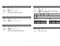
1
Warning - U.S
DATE: July. 2001
MANUAL REVISION 2.0
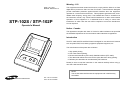
STP-102S / STP-102P
Operator's Manual
This equipment has been tested and found to comply with the limits for a Class A
digital device pursuant to Part 15 of the FCC Rules. These limits are designed to
provide reasonable protection against harmful interface when the equipment is
operated in a commercial environment. This equipment generates uses, and can
radiate radio frequency energy and, if not installed and uses in accordance with
the instruction manual, may cause harmful interference to radio communications.
Operation of this equipment in a residential area is likely to cause harmful
interference in which case the user will be required to correct the interference at
his own expense.
Notice - Canada
This Apparatus complies with class "A" limits for radio interference as specified in
the Canadian department of communications radio interference regulations.
Introduction
The STP-102S and STP-102P Roll Printer is designed for use with electric instruments
such as system ECR, POS, banking equipment peripheral equipment, etc.
The main features of the printer are as follows:
PO
WE
R
1. High speed printing
2. Low noise thermal printing.
3. RS-232 serial interface (STP-102S). Parallel interface (STP-102P).
4. The data buffer allows the unit to receive print data even during printing.
5. Different print densities can be selected by DIP switches.
ERR
OR
FEE
D
ON
LIN
E
Please be sure to read the instruction in this manual carefully before using your
new STP-102S and STP-102P.
NOTE
The socket-outlet shall be near the equipment and it shall be easy
accessible.
ELECTRO- MECHANICS
TEL : 82-31-210-5620
FAX : 82-31-210-5589
Chapter 1. Unpacking
Table of Contents
1-1. Checking the contents of the Printer.
Chapter 1. Unpacking
1-1.
1-2.
1-3.
1-4.
Checking the contents of the Printer
Locating the Printer
Printer Part names
Operating Control Panel
Chapter 2. Connecting the cable
2-1. Connecting the AC adapter to your printer
2-2. Connecting the Printer to your computer
4
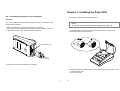
The items illustrated below are included with your printer.
If any items are damaged or missing, please contact your
dealer for assistance.
4
4
5
6
7
7
8
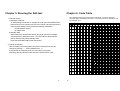
Chapter 3. Installing the Paper Roll
10
Chapter 4. Setting the DIP Switching
11
Roll paper
Printer
Chapter 5. Running the Self Test
13
Chapter 6. Code Table
14
Power cord
Adaptor
Cable
Chapter 7. Functions
21
Chapter 8. Control Commands
23
APPENDIX A - Connectors
- Serial Type (STP-102S)
- Parallel Type (STP-102P)
APPENDIX B - Specification
1-2. Locating the Printer.
Avoid location in direct sunlight or excessive heat.
Avoid or storing the printer in the place subject to excessive moisture.
Do not use or store, horizontal surface for the printer. Avoid places subject to
intense vibration or shock.
Make sure that there is enough space around the printer so that it can be used easily.
34
34
34
35
3
4
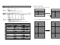
1-4. Operating Control Panel
1-3. Printer Part Names
The control panel has two buttons and two lights.
(1) Cover top
(2) Case top
(3) Case bottom
(4) Control panel
(5) Roller
(6) Power switch
(7) Interface connector (male)
(8) DC Jack
(9) Interface connector (female)
(10) Roll paper
(11) Detector switch
(10)
(5)
(1)
POWER ERROR
Rear View
(11)
FEED
ON LINE
Buttons
The control panel buttons perform paper feeding and on line function.
ON LINE
Press the ON LINE button to ready to receive data from the computer.
FEED
Press the FEED button once to advance paper one line. You can also press the FEED
button continuously to feed paper continuously.
Feed button is valid when ON LINE button is off.
(2)
(4)
(3)
Indicator lights
Rear View
The control panel lights provide information on printer conditions.
(6)
(7)
(8)
(9)
POWER(green)
The POWER light is on when the printer power is on.
STP-102S
ERROR(red)
STP-102P
1) The error LED blinks fast when paper is out.
2) The error LED blinks when the Near End Sensor triggered.
Control Panel
POWER ERROR
FEED
ON LINE
5
6
Chapter 2. Connecting the Cable
2-1. Connecting the AC adapter to your printer
2-2. Connecting the printer to your Computer
When the printer is used, use te optional AC adapter, AP-1611-UV for your printer.
STP-102S
Using an incorrect power supply may cause fire or electrical.
You need an appropriate serial interface cable to connect your computer to the
printer's built-in interface.
1. Make sure that both the printer and computer are turned off :
then plug the cable connector securely into the printer's interface connector.
2. Tighten the screws on both sides of the cable connector.
When connecting or disconnecting the power supply from the printer, make sure that
the power supply is not plugged into an electrical outlet ; otherwise you may damage
the power supply or the printer
1. Make sure that the printer's power switch is turned off, and that the power supply's
power cord is unplugged from the electrical outlet.
2. Check the label on the power supply to make sure that the requird voltage matches
that of your electrical outlet.
3. Plug the power supply's DC cable connector into the printer's power connector as
shown below.
25 Pin Male Type
STP-102S / STP-102P
3. Plug the other end of the cable into the computer
4. Plug the AC adapter's power cord into an electrical outlet.
NOTE
To remove the DC cable connector grasp the connector at the arrow and
pull it straight out. Make sure that the main unit's power cord is unplugged
before you disconnect the DC cable connector.
7
8
Chapter 3. Installing the Paper Roll
2-2. Connecting the printer to your Computer
Use a paper roll that matches the specifications.
STP-102P
You need an appropriate serial interface cable to connect your computer to the
printer's built-in interface.
NOTE
The printer must be turned off before installing the paper roll.
1. Make sure that both the printer and computer are turned off :
then plug the cable connector securely into the printer's interface connector.
2. Tighten the screws on both sides of the cable connector.
1. Open the printer cover and remove the used paper roll core if there is one.
2. Insert the paper roll as shown below.
25 Pin Female Type
3. Plug the other end of the cable into the computer
3. Pull out the paper roll until the paper comes out from the top of the printer. Then
close the printer cover.
4. Turn on the Printer.
9
10
Chapter 4. Setting the DIP Switches
DIP switch functions
CAUTION
Turn off the printer while setting the DIP switch to prevent an electrical short, which can
damage the printer.
No.
1
You can change your interface and printer density settings by changing the DIP switch
setting.
2
1. Make sure the printer is turned off.
2. There are a switch. Notice that ON is marked on each set of switches.
Use tweezers or another narrow tool to move the switches.
3
4
5
6
7
8
Level
1
2
3
4
5
6
7
Function
Density
Handshaking
Reserved
Language
Reserved
Dip Switch
BPS
D/W1
2400
ON
4800
OFF
9600
OFF
19200
ON
38400
ON
57600
OFF
115200
ON
ON
Dark
Xon/Xoff
Engish
-
NOTE
Dip Switch 7 must be always set to ON condition.
1
3. Use the following tables to set the DIP switches.
11
12
D/W2
OFF
ON
OFF
OFF
ON
ON
ON
OFF
Normal
DTR/DSR
Korean
-
S/W3
OFF
OFF
ON
ON
OFF
ON
ON
Chapter 6. Code Table
Chapter 5. Running the Self-test
The following pages show the character code tables. To find the character
corresponding to a hexadecimal number, count across the top of the table for the
For example, 4A=J.
1. Self-test printing
1) Starting the self test
To start printing the self-test on a paper roll, hold down the PAPER FEED
button and turn on the printer with the cover closed. The self-test prints the
current printer settings, which provide the following information :
- control software version
- dip switch state
2) Standby state
After printing the current printer status, the printer prints the message
"Please press the FEED BUTTON.". The LED indicator blinks and the
printer enter the test printing standby state.
Press the FEED BUTTON to start test printing.
2. Ending the self-test
After a number of lines are printed, the printer indicates the end of the
self-test by printing " ** TEST COMPLETED ** ".
If the self-test is completed, then you must reboot your printer.
Followings are the self-test results with STP-102S and STP-102P.
13
14
PC860 : Portuguese
PC850 : Multilingual
15
16
PC863 : Canadian - French
PC865 : Nordic
17
18
Space Page
19
20
Chapter 7. Functions
The commands listed in the table below are available for control of the printer.
Commands
Name
Command
Command Classification
Executing
Setting
Standard
Mode
Command
Name
HT
Horizontal tab
ESC \
Set relative print position
LF
Print and line feed
ESC a
Select justification
ESC SP
Set right-side character spacing
ESC c5
Enable/disable panel buttons
ESC !
Select print mode(s)
ESC d
Print and feed paper n lines
ESC $
Set absolute print position
ESC {
Turn upside-down printing mode on/off
Select/cancel user-defined character set
GS $
Select haracter size
Define user-defined characters
GS /
Define downloaded bit image
Select bit-image mode
GS :
Start/end macro definition
ESC -
Turn under line mode on/off
GS B
Turn white/black reverse printing mode on/off
ESC 2
Select 1/6-inch line spacing
GS L
Set left margin
ESC 3
Set line spacing
GS P
Set vertical and horizontal motion units
ESC ?
Cancel user-defined characters
GS W
Set printing area width
ESC @
Initialize printer
GS ^
Execute macro
ESC D
Set horizontal tab positions
GS h
Set bar code height
GS k
print bar code
GS w
Set bar code width
ESC %
ESC &
ESC *
ESC E
Turn emphasized mode on/off
ESC J
Print and feed paper
ESC R
Select an international character set
ESC S
Select standard mode
ESC V
Turn 90 clockwise rotation mode on/off
Command Classification
Executing
Setting
Standard
Mode
(
)
(
)
Command classification
Executing : Printer executes the command, which does not affect the following data.
Setting : Printer uses flags to make setting, and those setting affect the following data.
Standard mode
(
21
22
: Enagled
Enabled only when the command is used at the beginning of a line.
: Enabled only when data is not present in the buffer.
):
Chapter 8. Control Commands
ESC SP n
[Name]
[Format]
[Range]
[Description]
Command Notation
[Name]
[Format]
[Range]
[Description]
The name of the command.
the code sequence.
ASCII indicates the ASSCII equivalents.
Hex indicates the hexadecimal equivalents.
Decimal indicates the decimal equivalents.
[ ] k indicates the contents of the [ ] should be repeated k times.
Gives the allowable ranges for the arguments.
Describes the function of the command.
ESC ! n
[Name]
[Format]
Bit
0
2
3
Least Significant Bit
4
Control Commands
5
HT
[Name]
[Format]
[Description]
Select print modes.
ASCII
ESC
!
n
Hex
1B
21
n
Decimal
27
33
n
0 < n < 255
Selects print mode(s) using n as follows:
[Range]
[Description]
Explanation of Terms
LSB
Set right-side character spacing.
ASCII
ESC
SP
n
Hex
1B
20
n
Decimal
27
32
n
0 < n < 255
Sets the character spacing for the right side of the character to n dots.
6
7
Horizontal tab.
HT
ASCII
09
Hex
9
Decimal
Moves the print position to the next horizontal tab position.
1
Off/On
Off
On
Off
On
Off
On
Off
On
Off
On
On
Hex
00
01
00
08
00
10
00
20
00
80
02
Decimal
0
1
0
8
0
16
0
32
0
128
2
Function
24 char
42 char
Undefined.
Emphasized mode not selected.
Emphasized mode selected.
Double-height mode not selected.
Double-height mode selected.
Double-width mode not selected.
Double-width mode selected.
Undefined.
Underline mode not selected.
Underline mode selected.
32 char
* Determine the values of n by adding the value of all the characteristics you want to select.
LF
[Name]
[Format]
[Description]
Print and line feed.
ASCII
LF
Hex
0A
Decimal
10
Prints the data in the print buffer and feeds one line based on the current
line spacing.
ESC-$ nL nH
[Name]
[Format]
[Range]
[Description]
23
24
Set absolute print position.
ASCII
ESC
$
nL
nH
Hex
1B
24
nL
nH
Decimal
27
36
nL
nH
0 < nL < 255
0 < nH < 255
Set the print starting position from the beginning of the line.
The distance from the beginning of the line to the print position is
(nL + nH x 256) dots.
ESC * m nL nH d1...dk
ESC 3 n
[Name]
[Format]
[Name]
[Format]
[Range]
[Description]
[Notes]
Select bit-image mode.
ASCII
ESC
m nL nH d1 ... dk
*
2A
Hex
1B
m nL nH d1 ... dk
42
Decimal 27
m nL nH d1 ... dk
m = 0, 1, 32, 33
0 < nL < 255
0 < nH < 3
0 < d < 255
Selects a bit-image mode using m for the number of dots specified by nL and
nH, as follows.
Number of data(k) = (nL + nH x 256) x 3
[Range]
[Description]
Set line spacing.
ASCII
ESC
3
Hex
1B
33
Decimal
27
51
0 < n < 255
Sets the line spacing to n dots.
n
n
n
ESC @
The nL and nH indicate the number of dots of the bit image in the horizontal
direction.
The number of dots is calculated by (nL + nH x 256).
If the bit-image data input exceeds the number of dots to be printed on a line,
the excess data is ignored.
d indicates the bit-image data. Set a corresponding bit to 1 to print a dot or
to 0 to not print a dot.
[Name]
[Format]
[Description]
Initialize printer.
@
ASCII
ESC
40
Hex
1B
64
Decimal
27
Clears the data in the print buffer and resets the printer mode
to the mode that was in effect when the power was turned on.
ESC D n1...nk NUL
[Name]
[Format]
ESC - n
[Name]
[Format]
[Range]
[Description]
n
0, 48
1, 49
2, 50
Turn underline mode on/off.
ASCII
ESC
n
Hex
1B
2D
n
Decimal
27
45
n
0 < n < 2, 48 < n < 50
Turns underline mode on or off, based on the following values of n:
Function
Turns off underline mode.
Turns on underline mode (1-dot thick).
Turns on underline mode (2-dots thick).
[Range]
[Description]
[Notes]
Set horizontal tab positions.
ESC
D
ASCII
1B
44
Hex
27
68
Decimal
1 < n < 255
0 < k < 32
Sets horizontal tab position.
n1...nk
n1...nk
n1...nk
NUL
00
0
n specifies the column number for setting a horizontal tab position
from the beginning of the line.
k indicates the total number of horizontal tab positions to be set.
ESC E n
[Name]
[Format]
ESC 2
[Name]
[Format]
[Description]
Select default line spacing.
ASCII
ESC
2
Hex
1B
32
Decimal
27
50
Set the line spacing to 1/6 inch.
[Range]
[Description]
[Notes]
25
26
Turn emphasized mode on/off.
ESC
E
ASCII
n
1B
45
Hex
n
27
69
Decimal
n
0 < n < 255
Turns emphasized mode on or off.
When the LSB is 0, emphasized mode is turned off.
When the LSB is 1, emphasized mode is turned on.
ESC \ nL nH
ESC J n
[Name]
[Format]
[Range]
[Description]
[Name]
[Format]
Print and feed paper.
n
ESC
ASCII
J
n
1B
Hex
4A
n
27
Decimal
74
0 < n < 255
Prints the data in the print buffer and feeds the paper n dots.
[Range]
[Description]
ESC R n
[Notes]
[Name]
[Format]
[Range]
[Description]
n
0
1
2
3
4
Select an international character set.
n
R
ESC
ASCII
n
52
1B
Hex
n
82
27
Decimal
0 < n < 10
Selects an international character set n from the following table.
n
5
6
7
9
10
Character set
U.S.A.
France
Germany
U.K.
Denmark I
[Name]
[Format]
Character set
Sweden
Italy
Spain
Norway
Denmark II
[Range]
[Description]
n
0, 48
1, 49
2, 50
ESC
1B
27
V
56
86
n
n
n
[Notes]
[Range]
[Description]
n
0, 48
1, 49
[Notes]
This command sets the distance from the current position to (nL + nH x 256) dots.
Any setting that exceeds the printable area is ignored.
ESC a n
ESC V n
[Name]
[Format]
Set relative print position.
ESC
\
ASCII
1n, nH
1B
5C
Hex
1n, nH
27
92
Decimal
1n, nH
0 < nL < 255
0 < nH < 32
Set the print starting position based on the current position by
using the horizontal or vertical motion unit.
[Default]
[Example]
Function
Select justification.
ESC
a
ASCII
n
1B
61
Hex
n
27
97
Decimal
n
0 < n < 2, 48 < n < 50
Aligns all the data in one line to the specified position.
n selects the type of justification as follows:
Justification
Left justification
Centering
Right justification
The command is enabled only when input at the beginning of the line.
Lines are justified within the specified printing area.
Spaces set by HT, ESC $, and ESC \ are all justified.
n=0
Left justification
ABC
ABCD
ABCDE
When underline mode is turned on, the printer does not underline 90
clockwise-rotated characters.
Double-width and double-height commands in 90 rotation mode enlarge
characters in the opposite directions as from double-height and double-width
commands in normal mode.
These command has no effect in page mode.
If this command is input in page mode, the printer performs only internal flag
operations.
27
28
Centering
ABC
ABCD
ABCDE
Right justification
ABC
ABCD
ABCDE
ESC c 5 n
[Name]
[Format]
[Range]
[Description]
GS ! n
Enable/Disable panel buttons.
ASCII
ESC
c
5
Hex
1B
63
35
Decimal
27
99
53
0 < n < 255
Enables or disables the panel buttons.
[Name]
[Format]
n
n
n
[Range]
[Description]
[Notes]
When the LSB is 0, the panel buttons are enabled.
When the LSB is 1, the panel buttons are disabled.
Bit
ESC d n
[Name]
[Format]
[Range]
[Description]
Print and feed n lines.
ASCII
ESC
d
n
Hex
1B
64
n
Decimal
27
100
n
0 < n < 255
Prints the data in the print buffer and feeds n lines.
Select character size.
ASCII
GS
!
n
Hex
1D
21
n
Decimal
29
33
n
0 < n < 255
(1 < vertical number of times < 8, 1 < horizontal number of times < 8)
Selects the character height using bits 0 to 1 and selects the character width
using bits 4 to 5, as following:
Off/On
Hex
Decimal
0~1
Character height selection. See Table 2
4~5
Character width selection. See Table 1
Table 1
Character Width Selection
Hex
Decimal
Width
00
0
1(normal)
10
16
2(double)
ESC { n
[Name]
[Format]
[Range]
[Description]
[Notes]
Turn upside-down printing mode on/off.
ASCII
ESC
{
n
Hex
1B
7B
n
Decimal
27
123
n
0 < n < 255
Turns upside-down printing mode on or off.
GS :
[Name]
[Format]
When the LSB is 0, upside-down printing mode is turned off.
When the LSB is 1, upside-down printing mode is turned on.
[Description]
29
30
Start/End macro definition.
ASCII
GS
:
Hex
1D
3A
Decimal
29
58
Starts or ends macro definition.
Function
Table 2
Character Height Selection
Hex
Decimal
Width
0
00
1(normal)
1
10
2(double)
GS W nL nH
GS B n
[Name]
[Format]
[Range]
[Description]
[Name]
[Format]
Turn white/black reverse printing mode on/off.
ASCII
GS
B
n
Hex
1D
42
n
Decimal
29
66
n
0 < n < 255
Turn on or off white/black reverse printing mode.
[Range]
[Description]
[Notes]
When the LSB is 0, white/black reverse printing mode is turned on.
When the LSB is 1, white/black reverse printing mode is turned off.
[Notes]
Set printing area width.
ASCII
GS
W
nL
nH
Hex
1D
4C
nL
nH
Decimal
29
87
nL
nH
0 < nL < 255
0 < nH < 255
Set the printing area width to the area specified by nL and nH.
The printing area width is set to (nL + nH x 256) dots.
Printable area
GS L nL nH
[Name]
[Format]
[Range]
[Description]
[Notes]
Left margin
Set left margin.
ASCII
GS
L
nL
nH
Hex
1D
4C
nL
nH
Decimal
29
76
nL
nH
0 < nL < 255
0 < nH < 255
Sets the left margin using nL and nH in standard mode.
This command is effective only at the beginning of a line.
The maximum possible setting for the print range is the same as the maximum
setting are rounded down to the maximum setting.
GS ^ r t m
The left margin is set to (nL + nH x 256) dots from the beginning of the line.
This command is effective only at the beginning of a line.
[Name]
[Format]
Printable area
[Range]
Left margin
Printing area width
Printing area width
[Description]
[Notes]
31
32
Execute macro.
ASCII
GS
Hex
1D
Decimal
29
0 < r < 255
0 < t < 255
0<m<1
^
5E
92
rtm
rtm
rtm
Executes a macro.
r specifies the number of times to execute the macro.
t specifies the waiting time for exceuting the macro.
The waiting time is t x 100m sec for every macro execution.
When m = 0 : the macro executes r times continously width interval specified by t.
When m = 1 : After waiting for the period specified by t, the PAPER OUT LED
indicator blinks and the printer waits for the FEED button to be pressed.
After the button is pressed, the printer executes the macro once. The printer
repeats the operation r times.
APPENDIX A: CONNECTORS
GS h n
[Name]
[Format]
Set bar code height.
ASCII
GS
h
n
Hex
1D
68
n
Decimal
29
104
n
1 < n < 255
Set the height of the bar code.
n specifies the number of dots in the vertical direction.
[Range]
[Description]
SERIAL INTERFACE CONNECTOR (STP-102S)
PRINTER
20
19
21
22~25
18
1 GS k m d1... dk NUL, 2 GS k m n d1... dn
[Name]
Print bar code.
1 ASCII
[Format]
GS
k
m
d1...dk NUL
Hex
1D
68
m
d1...dk 00
Decimal
29
104
m
d1...dk 0
2 ASCII
GS
k
m
n d1... dn
Hex
1D
68
m
n d1... dn
Decimal
29
104
m
n d1... dn
[Range]
1 0 < m < 6 (k and d depends on the bar code system used.)
2 65 < m < 73 (n and d depends on the bar code system used)
[Description]
Selects a bar code system and prints the bar-code.
m selects a bar code system as follows.
d indicates the character code to be printed and k indicates the number of
characters to be printed.
m
1
0
1
2
3
4
Bar Code System
UPC-A
UPC-E
JAN13(EAN)
JAN8(EAN)
CODE39
Number of Characters
11 < k < 12
11 < k < 12
12 < k < 13
7<k<8
1<k
5
6
ITF
CODABAR
1 < k (even number)
1<k
65
66
67
68
69
UPC-A
UPC-E
JAN13(EAN)
JAN8(EAN)
CODE39
11 < n < 12
11 < n < 12
12 < n < 13
7<n<8
1 < n < 255
70
71
ITF
CODABAR
1 < n < 255 (even number)
1 < n < 255
72
73
CODE93
CODE128
1 < n < 255
2 < n < 255
2
HOST
TXD(O)
RXD(I)
CTS(I)
GND
RTS(O)
25 PINE MALE
CONNECT
2
3
7
5
8
4
6
RXD(I)
TXD(O)
RTS(O)
GND
CTS(I)
DTR(O)
DSR(I)
9 PINE MALE
PARALLEL INTERFACE CONNECTOR (STP-102P)
PRINTER
1
/STROBE(I/O)
2
DATA0(I/O)
3
DATA1(I/O)
4
DATA2(I/O)
5
DATA3(I/O)
6
DATA4(I/O)
7
DATA5(I/O)
8
DATA6(I/O)
9
DATA7(I/O)
10
/ACK(I)
11
BUSY(I)
12
PE(I)
SLCT
13
/ERROR(I)
15
N.C
16~21
GND
22~25
25 PINE FEMALE
Remarks
48 < d < 57
48 < d < 57
48 < d < 57
48 < d < 57
48 < d < 57, 65 < d < 90
d = 32,36,37,43,45,46,47
48 < d < 57
48 < d < 57, 65 < d < 68
d = 36,43,45,46,47,58
48 < d < 57
48 < d < 57
48 < d < 57
48 < d < 57
48 < d < 57, 65 < d < 90
d = 32,36,37,43,45,46,47
48 < d < 57
48 < d < 57, 65 < d < 68,
d = 36,43,45,46,47,58
0 < d < 127
0 < d < 127
33
34
HOST
1
/STROBE(I/O)
2
DATA0(I/O)
3
DATA1(I/O)
4
DATA2(I/O)
5
DATA3(I/O)
6
DATA4(I/O)
7
DATA5(I/O)
8
DATA6(I/O)
9
DATA7(I/O)
10
/ACK(I)
11
BUSY(I)
12
PE(I)
SLCT
13
/ERROR(I)
15
/INIT(O)
16
GND
18~25
25 PINE FEMALE
APPENDIX B: Specification
Printing method
Thermal line printing
Dot density
200 x 200 Dpi (8 dot/mm)
Printing width
48mm
Paper width
58mm
Characters per line
42 (Font A)(12x24) ,56(Font B)(9x24)
Approximately 1.97 inchs/sec
Printing speed
50 mm/sec
at 25°C/printing duty 12.5%
Receive buffer size
15K bytes
7.5V
Supply voltage
Temperature
2.2A
0 ~ 40°C (operating)
-10 ~ 50°C (storage)
Environmental conditions
Humidity
30 ~ 80% RH (operating)
10 ~ 90% RH (storage)
MCBF
Mechanical
15,000,000 line
Head
50 million pulse (about 50km)
Paper
- Paper thickness : 0.06 ~ 0.09mm
- Roll size : 60 ~ 57(w)
- Roll spool diameter
1) Inside : 12mm (0.47")
2) Outside : 18mm (0.71")
JF01-000012
35