1
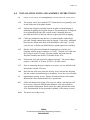
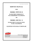
IP-HOB-531-X OR SSP-511-X-SPK1.07r1-ISSUE4.0 SERVICE MANUAL FOR VoIP MODEL IP-HOB-531-X HANDS FREE WEATHER RESISTANT TELEPHONE OR MODEL IP-SSP-511- X HANDS FREE STAINLESS STEEL PANEL TELEPHONE EQUIPPED WITH SPK1.07r1 FIRMWARE Serving the Telephone Industry Since 1930 Communication Equipment & Engineering Company 519 West South Park Street Okeechobee, Florida 34972 Voice: 863-357-0798 Fax: 863-357-0006 ISSUE 4.0 IMPORTANT INFORMATION FOR CUSTOMER Please fill in before you continue. The following information is necessary when calling CEECO for assistance. MODEL NUMBER MODEL IP-HOB-531-X OR SSP-511-X EQUIPPED WITH SPK1.07r1 FIRMWARE. SERIAL NUMBER DATE MANUFACTURED LOCATION INSTALLED For us to better serve you, please have this information available when calling for technical support. CEECO Communication Equipment & Engineering Company 519 West South Park Street Okeechobee, Florida 34972 (863) 357-0798 Voice (863) 357-0006 Fax CEECO Communication Equipment & Engineering Company PROPRIETARY 2 ISSUE 4.0 TABLE OF CONTENTS SECTION PAGE 1.0 INTRODUCTION................................................................................................. 4 2.0 GENERAL ............................................................................................................. 4 3.0 PROGRAMMING ................................................................................................ 5 PROGRAMMING CONTINUED ....................................................................... 6 PROGRAMMING CONTINUED ....................................................................... 7 4.0 OPERATION ........................................................................................................ 7 5.0 RECOMMENDED TOOLS AND TEST EQUIPMENT .................................. 7 6.0 INSTALLATION NOTES AND ASSEMBLY INSTRUCTIONS ................... 8 7.0 TESTING ............................................................................................................... 9 8.0 SPECIFICATIONS............................................................................................. 10 9.0 PARTS LIST ....................................................................................................... 11 10.0 FCC NOTICE...................................................................................................... 12 11.0 REPAIR AND RETURN INFORMATION ..................................................... 13 12.0 WARRANTY POLICY ...................................................................................... 14 13.0 DIAGRAM........................................................................................................... 15 CEECO Communication Equipment & Engineering Company PROPRIETARY 3 ISSUE 4.0 1.0 INTRODUCTION The practices in this manual provide installation and maintenance information for the CEECO Voice Over Internet Protocol (VoIP) Model IP-HOB-531-X Hands free Weather Resistant Telephone or Model IP-SSP-511-X Stainless Steel Panel Telephone, equipped with SPK1.07r1 firmware. The information in this manual is subject to change without notification. For information not included in this manual, please call or write: CEECO Customer Service 519 West South Park Street Okeechobee, Florida 34972 (863) 357-0798 (863) 357-0006 FAX 2.0 GENERAL 2.1 The CEECO Model IP-HOB-531-X Hands Free Weather resistant telephone is a sturdy, vandal resistant, stainless steel weather resistant speakerphone. Instead of a hookswitch and handset, the IP-HOB-531-X has a Press to start/Press to stop button for initiation and termination of phone calls. This Emergency button is provided for automatic ring down applications. Ordinarily, the telephone can only be used to receive calls. The telephone may, however, be used to initiate calls if it is used in conjunction with external call equipment (i.e. programmable switch, ring down circuit, etc…) The Model IP-SSP-511-X is the same telephone without the weather resistant housing. It is designed to be installed in either the HOB series weather resistant housings or the HOB series openfaced weather-resistant housings. 2.2 Incoming calls may be allowed or blocked depending on the programming. 2.3 Programming is accomplished via the DTMF keypad. *The VoIP ATA unit does require an AC power source as described in the installation notes. *The VoIP ATA typically comes in a separate but included package, but may also come already positioned within the telephone. CEECO Communication Equipment & Engineering Company PROPRIETARY 4 ISSUE 4.0 3.0 PROGRAMMING 3.1 Remove the front stainless steel panel by loosening the four security screws with a security tool (sold separately) and remove them. Remove the panel and attached telephone assembly. 3.2 Connect the telephone to a working telephone line or a DTMF test set. 3.2 Locate the pair of plastic mini-jumpers located near the edge of the printed circuit board. Move them to the “ON” or innermost position, as depicted on the last page of this manual. 3.3 Locate the programming keypad, which is either mounted on the back panel or provided on the side. If the keypad is packaged separately, locate the multicolored ribbon cable with white connector, which extends from the PC Board of the phone. Connect the keypad to that connector. 3.4 Each programming location is accessed by dialing the "#" sign and the two digit code, which corresponds to that location. The only valid program locations for this phone is #00. The previous contents of the location are automatically erased when the location code is dialed. 3.5 Press the “CALL & HANGUP” button and wait to hear dial tone. 3.6 Using the keypad, enter # 9 7 # 1 8 #. This will clear all user programmable memory to begin programming. 3.7 Location "00" is the telephone options location. By entering a number of 1-9 into each of the 10 digits, the phone is customized for the particular installation. 3.8 Enter #00 followed by ten digits, as selected on the next page. This “X” model phone only offers selections for Digits 2, 3, and 10 on the next page. It is recommended that a “5” be entered under Digit 10. NOTE: THIS EQUIPMENT IS TELEPHONE LINE POWERED. DURING PROGRAMMING THE CENTRAL OFFICE OR PBX MAY RESPOND TO THE PROGRAMMING CODES WITH VARIOUS BUSY TONE, REORDER TONE, RECORDINGS, ETC. THESE TONES AND RECORDINGS WILL HAVE NO EFFECT ON THE PROGRAMMING. PLEASE IGNORE THEM. CEECO Communication Equipment & Engineering Company PROPRIETARY 5 ISSUE 4.0 PROGRAMMING CONTINUED LOCATION #00 Digit 1: Always 0 for this model. Digit 2: 0 No incoming calls allowed. 1 Incoming calls allowed. Digit 3: 0 No time-out disconnect 1-9 Minutes time-out disconnect Digit 4: Always 0 for this model Digit 5: Always 1 for this model Digit 6: Always 0 for this model. Digit 7: Always 0 for this model Digit 8: Always 0 for this model Digit 9: Always 0 for this model Digit 10: 0 0 No wink detect. 1-9 Length of the wink detect. (1=50ms incremental to 450 ms. 5 is recommended). Be sure to enter your selections below for future reference. #00= 0 __ __ 0 1 0 0 0 0 5 DIGITS: 1 2 3 4 5 6 7 8 9 10 CEECO Communication Equipment & Engineering Company PROPRIETARY 6 ISSUE 4.0 PROGRAMMING CONTINUED 3.9 3.10 4.0 When you are finished programming, press the “CALL & HANGUP” button to hang up the phone. Return the two plastic mini-jumpers to the “OFF” or outermost position, as depicted on the last page of this manual. Secure the telephone assembly in the housing. The phone is now ready for use. Refer to the INSTALLATION NOTES section ahead for details regarding the VoIP configuration setup prior to proceeding. OPERATION To receive a call, press the "EMER/CALL" button located on the front of the phone, when the telephone rings. The LED (if provided) will illuminate red at this time. In order to receive incoming calls the phone must have been programmed with a “1” under Digit 2 in section 3.8 of this manual. When the call is answered, a normal speakerphone conversation may take place. After the call is complete, press the "EMER/CALL" button on the front of the panel again to hang up the phone. If the user does not press the button on the front of the panel when he or she is finished using the phone, then the phone will hang up after detecting a wink (open switch interval) or the timer times out. If the telephone has been mated with external call equipment, a call may also be initiated by pressing the “EMER/CALL” button. The LED (if provided) will illuminate red at this time. The external call equipment should direct the call as intended and a normal speakerphone conversation may take place. After the call is complete, press the "EMER/CALL" button on the front of the panel again to hang up the phone. If the user does not press the button on the front of the panel when he or she is finished using the phone, then the phone will hang up after detecting a wink (open switch interval) or the timer times out. 5.0 RECOMMENDED TOOLS AND TEST EQUIPMENT DTMF Test Set Volt/Ohm Meter CEECO Security Tool, 301-064 CEECO Communication Equipment & Engineering Company PROPRIETARY 7 ISSUE 4.0 6.0 INSTALLATION NOTES AND ASSEMBLY INSTRUCTIONS 6.1 Using a 301-064 security tool (sold separately) loosen and remove the security screws. 6.2 The security tool is for a standard 5/32" button head screw generally used on the framework of the phone booths. 6.3 Separate the faceplate assembly from the weather resistant housing or mounting by pulling the faceplate forward. The mounting box is designed to be mounted flush with a flat vertical surface. Mounting holes are provided on the back of the box and may require punch out or tapping. 6.4 Cables are intended to enter the box via conduit and the conduit holes provided. Unused conduit holes must be plugged. If necessary, additional holes may be drilled in the back of the housing for cable entry. In such cases, be sure to de-bur any drilled holes to guard against wire chaffing.. 6.5 Run the LAN cable/wire through the mounting box or surface and terminate with the proper connector (i.e. RJ45). Plug the LAN cable into the LAN port of the ATA unit. Plug the modular line cord from the faceplate assembly into the RJ11C terminal on the ATA. 6.6 Position the ATA unit and power adapter as desired. The power adapter requires a 100-240V, 0.3A max, 20-30VA, 50-60Hz source. 6.7 Prior to connecting the power adapter to its source, review and follow the instructions with the ATA unit. 6.8 Dress the line cable away from the security screws and seat the faceplate into the weather resistant housing or mounting. Secure the cover assembly tightening the security screws. Ensure all connections have been made, fasteners have been fastened and LAN is operational. by 6.9 Follow the instructions for the ATA setup, for which a web browser will be necessary, unless the DTMF input method is used as described for voice prompt configuration. Please utilize the contact information on the ATA documentation for any questions regarding VoIP settings or issues. 6.10 The unit is now ready for use. CEECO Communication Equipment & Engineering Company PROPRIETARY 8 ISSUE 4.0 *****WARNING***** A. B. Never install telephone wiring during a lightning storm. The telephone must be grounded in accordance with local and national electric codes. Never install telephone jacks in wet locations unless the jack is specifically designed for wet locations. Never touch uninsulated telephone wires or terminals unless the telephone line has been disconnected at the network interface. Use caution when installing or modifying telephone lines. C. D. E. 7.0 TESTING Action: Connect the telephone to a working telephone line. Place a call to the telephone from another phone. Reaction: The telephone rings. Press the "CALL" button to answer the call. Provided the phone was programmed to allow incoming calls, a normal speakerphone conversation should transpire. Action: Finish the conversation. Press the "CALL" button, or wait until Time-out occurs. Action: If the telephone has been mated with external call equipment, press the "CALL" button to initiate a call. Reaction: The external call equipment directs the call as intended and a normal speakerphone conversation is allowed when the called party answers. Action: Finish the conversation. Press the "CALL" button, or wait until Time-out occurs. Action: If the phone was programmed to not allow incoming calls, try making a call to the phone. Reaction: The telephone will ring, but it will drop the line when it is answered and not allow a conversation to take place. *NOTE: Please utilize the contact information on the ATA documentation for any questions or issues pertaining to the VoIP settings or use CEECO Communication Equipment & Engineering Company PROPRIETARY 9 ISSUE 4.0 8.0 SPECIFICATIONS INPUT POWER: ATA powered LOOP CURRENT: 35 mA minimum 80 mA maximum IMPEDANCE: 600 ohms SIGNALING: Manual on-off hook ENVIRONMENTAL: Temperature 0o C to 50o C Humidity 20%-90% non-condensating PROGRAMMING: Via DTMF keypad. MEMORY RETENTION: Non-volatile memory retention DIMENSIONS: (SSP) 7 1/6 wide x 11 1/4 high x 4 1/4 deep MOUNTING: Vertical surface mount. WEIGHT: Approximately 4 lb. DIMENSIONS: (HOB) 11.28" high x 7.080" wide x 5" deep (top) MOUNTING: 4 Holes spaced 8" x 5 7/8"by .312" dia. WEIGHT: Approximately 12 pounds FCC REGISTRATION NO.: BW-88T7-68447-KX-T TYPE JACK: RJ11C UL LISTED NO.: 6OF5 CEECO Communication Equipment & Engineering Company PROPRIETARY 10 ISSUE 4.0 9.0 PARTS LIST QUANTITY PART NUMBER DESCRIPTION 4 331-006 OUTER COVER SECURITY SCREW 1 301-018 MODULAR LINE CORD 1 531-11075 FACE PLATE 1 700-008 KEYPAD CABLE 1 660-000 CEECO SPEAKER BOARD 1 705-110 CONNECTORIZED KEYPAD 1 14067 1 6020 1 14024 1 HOB-331 Open-faced weather-resistant enclosure 1 331-010 STAINLESS STEEL PANEL. 1 401-009 RINGER 1 N/A 1 MICROPHONE. MOMENTARY PANEL SWITCH SPEAKER SERVICE MANUAL 301-12062 VoIP ATA Unit 301-064 SECURITY TOOL ACCESSORIES: 1 CEECO Communication Equipment & Engineering Company PROPRIETARY 11 ISSUE 4.0 10.0 FCC NOTICE 10.1 FCC REGISTRATION AND REPAIR INFORMATION Your new telephone has been registered with the Federal Communication Commission (FCC) in accordance with Part 68 of its rules. The FCC requires that you be advised of certain requirements involving the use of this telephone. 10.2 CONNECTION WITH THE NATIONWIDE TELEPHONE NETWORK The FCC requires that you connect this telephone to the Nationwide Telephone Network through a registered jack provided by the Telephone Company in your area. This jack is a modular outlet, which you can order from your local telephone company. 10.3 NOTIFICATION TO THE TELEPHONE COMPANY Before connecting this telephone, the FCC requires that you notify your local telephone company business office. The number is in the front of your phone book. Tell them: The "line" to which you will connect the telephone (that is, your phone number) and the telephone's FCC registration number and ringer equivalence number. These numbers are listed in Section 8.00. The FCC further requires that you notify your local telephone company when permanently disconnecting this telephone. NOTE: This section does not apply to those units being used solely on a LAN network. CEECO Communication Equipment & Engineering Company PROPRIETARY 12 ISSUE 4.0 11.0 REPAIR AND RETURN INFORMATION 11.1 WARRANTY REPAIR Any device returned requiring warranty service, repair or credit must be accompanied with a "Return Material Authorization" (RMA) FORM. It must include: return-shipping instructions, original purchase order number and special marking instruction. A description of the trouble observed must be attached to the defective unit. This information must be inside the shipping container. 11.2 DIRECT ALL INQUIRES TO: CEECO Repair Department 519 West South Park Street Okeechobee, Florida 34972 (863) 357-0798 (863) 357-0006 FAX 11.3 NON-WARRANTY REPAIR CEECO will repair equipment out of warranty for a set charge plus parts. The customer must pay the shipping costs both directions. 11.4 RETURN FOR CREDIT Material may be returned for credit only with prior approval. Material authorized for return is subject to a 20% restocking charge based on the manufacturer’s list price. Return RMA must be requested no later than 30 days after original shipment. CEECO Communication Equipment & Engineering Company PROPRIETARY 13 ISSUE 4.0 12.0 WARRANTY POLICY 12.1 GENERAL CEECO products are guaranteed to be free of defects in material and workmanship for a period of 365 days from the date of original purchase. CEECO's obligation under this warranty is limited to repair or replacement of any part found to be defective by CEECO. Under no circumstances shall CEECO be liable for loss, damage, cost of repair or consequential damages of any kind, which have been caused by neglect, acts of God, abuse or improper operation of equipment. 12.2 PRINTED CIRCUIT BOARDS Printed circuit boards should not be repaired in the field. If a unit is found to be faulty, replace it with another unit and return the faulty unit to CEECO for repair. Modifications by anyone other than CEECO will void the warranty. CEECO Communication Equipment & Engineering Company PROPRIETARY 14 ISSUE 4.0 13.0 DIAGRAM Locate the mini jumpers on the corner of the PCB. O N O MOVE THE MINI JUMPERS TO THE ON POSITION BEFORE GOING OFFHOOK. When programming is completed, move the mini jumpers to the OFF position. O FF N O O FF N O FF NOTE: Do not leave the mini jumpers in the ON position, this will decrease battery life. CEECO Communication Equipment & Engineering Company PROPRIETARY 15