1
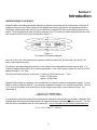
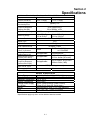
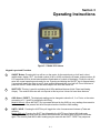
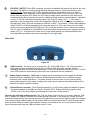
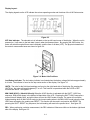
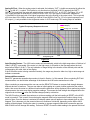
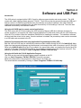
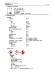
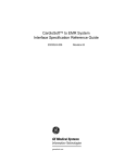
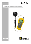
4100 Series ELF Gauss/Tesla Meter Instruction Manual Manual UN-01-263 Rev. D Pacific Scientific OECO All rights reserved. INTRODUCTION Table of Contents SECTION-1 INTRODUCTION Understanding Flux Density............................................... General Operating Instructions.......................................... 1-1 1-2 SECTION-2 SPECIFICATIONS Meter Specifications.......................................................... 2-1 SECTION-3 OPERATING INSTRUCTIONS Keypad layout and functions.............................................. Meter Ports………............................................................. Display Layout…............................................................... Advanced Measurements.................................................... 3-1 3-3 3-3 3-3 SECTION-4 SOFTWARE AND USB PORT Introduction…………………............................................... Connecting the 4100 Series to a PC ……………………… 4-1 4-2 WARRANTY....................................................................... 5-1 Section 1 Introduction UNDERSTANDING FLUX DENSITY Magnetic fields surrounding permanent magnets or electrical conductors can be visualized as a collection of magnetic flux lines; lines of force existing in the material that is being subjected to a magnetizing influence. Unlike light, which travels away from its source indefinitely, magnetic flux lines must eventually return to the source. Thus all magnetic sources are said to have two poles. Flux lines are said to emanate from the “north” pole and return to the “south” pole, as depicted in Figure 1-1. Figure 1-1 Flux Lines of a Permanent Magnet One line of flux in the CGS measurement system is called a maxwell (M), but the weber (W), which is 108 lines, is more commonly used. Flux density, also called magnetic induction, is the number of flux lines passing through a given area. It is commonly assigned the symbol “B” in scientific documents. In the CGS system a gauss (G) is one line of flux passing through a 1 cm2 area. The more commonly used term is the tesla (T), which is 10,000 lines per cm2 . Thus 1 tesla = 10,000 gauss 1 gauss = 0.0001 tesla Magnetic field strength is a measure of force produced by an electric current or a permanent magnet. It is the ability to induce a magnetic field “B”. It is commonly assigned the symbol “H” in scientific documents. The unit of “H” in the CGS system is an oersted (Oe), but the ampere-meter (Am) is more commonly used. The relationship is 1 oersted = 79.6 ampere-meter 1 ampere-meter = 0.01256 oersted It is important to know that magnetic field strength and magnetic flux density are not the same. Magnetic field strength deals with the physical characteristics of magnetic materials whereas flux density does not. The only time the two are considered equal is in free space (air). Only in free space is the following relationship true: 1 G = 1 Oe = 0.0001 T = 79.6 Am 1-1 INTRODUCTION General Operating Instructions and Application The 4100 Series ELF gaussmeter is designed to measure only AC magnetic fields. These include but are not restricted to the 50/60 Hz magnetic field emanating from power lines. ELF is an acronym similar to VHF or UHF as used for television band frequencies. ELF stands for Extremely Low Frequency and is defined as the band of frequencies from 30 to 300Hz. Although this meter will measure fields considerably above and below those defined limits, this is usually the bandwidth of primary interest since most ELF magnetic fields are power line related and within this bandwidth. To operate the 4100 Series meters, first press the ON/OFF button and wait for unit to initialize. Unit will start up in the last state it was when powered off. Move the 4100 towards a source of ELF radiation. Most appliances that plug into a standard wall socket and have a motor or power transformer or that draw higher currents will emit magnetic radiation when turned on. You should notice a change in the displayed reading as you move closer to the source of a radiated magnetic field. When you begin using the ELF gaussmeter, you will often find that the ELF field strength is strongest in one particular area. For example, your computer screen (CRT) may have its greatest field level directly in the back of it, thus affecting those around you. A bedside clock radio may emit a higher field level from its side where the power supply circuitry is located. You can effectively reduce your exposure to ELF magnetic fields by first locating the areas in your home or workplace where levels are the highest, and then by rearranging your living space in a way that minimizes your exposure. Hold the meter in front of and around the source of magnetic radiation, and position the meter in various locations until a maximum reading is obtained. Both the 4180 and the 4190 are three-axis meters and an individual axis can be selected. Take time to become familiar with this process and you will see that the reading displayed is greatly affected by the orientation of the meter when operating in single-axis mode. This is because the magnetic field not only has a magnitude or level but also a direction as well. The meter responds to the magnetic fields whose direction is aligned with the axis selected on the meter. Fields parallel in direction to the axis of the meter which has been selected will show a high reading in that direction and a low reading in others. Always keep these important points in mind when using the meter: (1) One single axis can be selected for finding the general direction of the field. When operating in single axis mode the position of the meter should be oriented in various directions until the maximum reading is obtained. (2) The maximum reading will give the true indication of field strength at that particular location. (3) In 3-axis mode (XYZ) the 4100 will indicate the field strength, but no directional information. The above process can be repeated at various locations to determine the area in the home or workplace where ELF magnetic fields are present. The Models 4180 and 4190 can assist you in locating the sources of ELF magnetic radiation in the home or workplace, and thus allow you to take prudent steps to reduce your exposure. As with most other forms of radiation, the level decreases as the distance from the source increases. Under normal operating conditions, the unit will provide about 30 hours of continuous operation using Alkaline batteries, or 20 hours for NiMH rechargeable batteries. When the battery voltage falls below approximately 4.44 volts (1.11 volts per cell), a low battery indicator on the LCD will be activated. Most rechargeable cells have a nominal voltage of 1.2V compared to 1.5V for alkaline cells, therefore the useable time before a low battery condition is indicated will be shorter than for alkaline batteries. However, if the meter is used frequently, rechargeable batteries will generally be much more economical since they may be re-used many times. Batteries contain ferrous magnetic materials which can alter the sensitivity of field readings if removed. The meter was calibrated at the factory with batteries installed. 1-2 Section 2 Specifications 4100 Series Electrical Specifications 23 ± 5°C, <85% RH Model 4180 Model 4190 Basic Accuracy (± 2% +1 digit) (± 1% +1 digit) (>0.4mG, 40-80 Hz) Additional Angular typically <1% Directionality Error 25 to 1200Hz, ±5% 20 to 2000Hz, ±15% Frequency Response (Display and USB) Update Rate (Display) Measuring Range Minimum Resolution 1000msec single axis, 1200msec 3-axis mode 0.1 to 599mG or 0.1 to 1999mG or 0.01 to 59.9 µT 0.01 to 199.9 µT 0.1 mG or 0.01µT LCD 3.5 digit Display Type Digits mGauss, µTesla Full Scale = 2.0Vdc or 1.0VacRMS Units of Measurement Analog Output 3.5mm, 2 conductor Sampling Rate (Analog Output, AC) Analog Output Accuracy (>0.4mG, 40 to 80Hz) Analog Output Frequency Response (Referenced to 55Hz) Communications Port Type ‘mini-B’, 5 pos. Data Logging Software NONE -Not applicable- 5k samples/sec -Not applicable- 1.5% ± 2mVdc (DC mode) 2.0% ± 4mVac (AC mode) -Not applicable- 25 to 1200Hz, ±5% ±10mV 20Hz to 2kHz (-3dB) USB (2 readings/sec max) No Yes Models 4180 and 4190 Battery Type Battery Life (Typical) Operating Temperature Storage Temperature External Power Supply for 120Vac Weight Size 4 – AAA, Alkaline 1.5V or NiMH 1.2V 30 hours for alkaline, 20 hours for 850mAh NiMH -10 to +50°C -20 to +60°C +5Vdc, 50mA minimum (part# 115003) 2.5mm ID x 5.5mm OD, center post + Approximately 6.25oz (177g) (with batteries) 4.7 x 3.0 x 1.45" (120 x 76 x 37mm) *Specifications apply only when unit has alkaline batteries installed. 2-1 Section 3 Operating Instructions Figure 3-1 Model 4190 shown Keypad Layout and Functions 1 ON/OFF Button. Pressing this key will turn on the meter. As the meter boots up it will emit a short audible beep, display “ELF”, the model number (4180 or 4190) and then the firmware version number. All LCD segments will then be activated and then deactivated as a check of the display. Finally the unit will enter into normal operating mode ready for use. Pressing and holding the ON/OFF key for approximately 2 seconds will cause the meter to emit 2 short audible beeps and then turn itself off. Do not continue to press the ON/OFF button after the two short beeps or the 4100 will remain on. 2 SHIFT KEY. This key is used for activating the 4190’s additional features (Hold / Reset and Analog Output). The model 4180 meter will not respond to this key since it does not have these features. 3 AXIS Select / RESET. The displayed reading can be changed to show the X, Y or Z axis, or the vector summation of X, Y and Z by pressing the AXIS key. Model 4190 only: When the SHIFT key is pressed followed by the AXIS key, any readings from max/min hold are reset and the present field level is acquired as the new Min or Max reading. 4 UNITS / HOLD. Pressing the UNITS key will toggle the units of measurement between µTesla and mGauss. Model 4190 only: Pressing the SHIFT key followed by the UNITS key will select MIN hold mode. Pressing this key sequence again will select MAX hold mode, and a third time will turn off hold mode again. The currently held MIN or MAX reading may be reset with the SHIFT- RESET key sequence. 3-1 5 RELATIVE / OUTPUT. When REL is selected, the meter will establish the present field level as the “new” zero point. This feature is useful for measuring field changes relative to a field level other than zero. Model 4190 only: By pressing SHIFT- REL, the analog output is activated and a DC or AC signal proportional to the field magnitude will be available at the analog output 3.5mm connector. The 4100 Series does not respond to DC fields, but a DC analog voltage output proportional to the field level is available and may be more easily connected to a data acquisition system or other equipment. Calibration is set to 2.0 Vdc full scale when the analog output is set to the DC mode ( OUT--- ). If the meter is operating on the low range then 2.0Vdc will correspond to 200mG or 20µT. If the meter is operating on the high range, then 2.0Vdc will correspond to 2000mG or 200µT. For example, 1.32Vdc could represent either 132.0mG or 1320mG depending which range the meter is on. The output when set to AC mode will be a time-varying signal which will allow the user to view the waveform on an oscilloscope if desired. The AC output is calibrated to 1.0VacRMS full scale and follows the typical frequency response curve as shown in Fig. 3.5. Just like the DC mode, the AC output signal voltage may represent different field levels depending on whether the meter is operating in low or high range. Meter Ports Figure 3-2 6 7 8 USB Connector. The meter can be connected to a PC via the USB 2.0 port. The 4190 can perform Data logging and be commanded through this port with the 4190 application software. Remote automation can also be performed through this port. The 4100 may also be powered from the +5 volt line of the USB connector, thus drawing its power from the computer to which it is attached. Analog Output Connector. (4190 only) A voltage signal representative of the magnetic flux density being measured is available at this connector which accepts a standard 3.5mm 2-conductor plug as commonly used in audio applications. The sleeve contact of the connector is circuit ground and the analog output signal is the tip contact. Loading of the output by any external equipment should be10 k minimum to prevent erroneous readings. External Power Connector. The 4100 series accepts a 5 volt DC power supply wall adapter for power. This optional adapter is available from Pacific Scientific OECO. Please call for pricing (part number 115003). Use of any other adapter could damage the meter and void the warranty. Powering the 4100 with multiple sources: The 4100 can obtain power from any of 3 sources: batteries, USB port, or external AC adapter connected to the External power connector. If more than one of these sources is connected simultaneously, the power will be drawn from whichever source has the highest voltage. For example if the voltage of the 4 batteries totals 4.8 volts and the USB is connected (which has 5.0 volts) the power will be drawn from the USB port instead of the batteries. However if new batteries are at 6.0 volts, power would be drawn from them rather than the USB port which is only 5.0 volts. 3-2 Display Layout: The display legends on the LCD indicate the various operating modes and functions of the 4100 Series meter. Figure 3-3 XYZ Axis indicator: The selected axis is indicated on the top left hand corner of the display. When the unit is powered on, it will return to the last state it was in when last powered down. By pressing the AXIS button, the meter will switch through all three axes individually, and the sum of all three (XYZ). The physical orientation of the meter’s measurement axes are shown in figure 3.4. Figure 3.4 Meter Axis Positions Low Battery Indicator: The low battery indicator is activated when the battery voltage falls below approximately 4.44 volts. The indicator is found on the top center section of the display. See figure 3-3. UNITS: The units for the field level readings are found on the right-hand side of the display. By pressing the UNITS key, the meter will toggle between µT or mG. This function is operational while the HOLD or REL functions are active. See figure 3-3. MIN / MAX (HOLD): (Model 4190 only) When the HOLD function is activated with the SHIFT- HOLD key sequence, MIN will be shown in the bottom left hand side of the LCD. Pressing the SHIFT-HOLD sequence a second time will display MAX, and a third time will turn the HOLD mode off again. The meter will record the highest reading when in MAX HOLD mode (or the lowest reading when in the MIN HOLD mode) since the time HOLD was activated or the reading was RESET. This function can be used in conjunction with RESET. By pressing the SHIFT- RESET key sequence, the held reading will reset to the present level. See figure 3-3. REL: When performing a relative measurement, the REL indicator will become visible on the bottom right-hand side of the display. See figure 3-3. 3-3 Analog OUTput: When the analog output is activated, the indicator “OUT” is visible accompanied by either the DC (---) or the AC (~) symbol. This feature is only functional on the Model 4190. By pressing the SHIFT– OUTPUT key sequence the meter will switch between output off, DC OUT, or AC OUT. See figure 3-3. In DC OUT mode the signal is calibrated to 2.0Vdc full scale. In AC OUT the signal is a waveform calibrated to 1.0VacRMS full scale and rolls off at higher frequencies due to the filtering in the output circuit. This is typically ±3% from about 30 to 500Hz, decreasing to -3dB at 20 and 2000Hz. See Fig. 3.5 for a typical response curve. AC output (~) is only available in the single axis modes. In XYZ mode only a DC analog output is available. X,Y Display Z Display Typical Frequency Response Curves Analog Out, AC Mode 5% 0% %Error -5% -10% -15% -20% -25% -30% 10 100 Frequency, Hz 1000 10000 Figure 3.5 Auto-Ranging Feature: The 4100 series meters will automatically switch to the high range when a field level of 198mG (19.8µT) is exceeded. If the meter is in the high range, it will switch to the low range when the level drops below 188mG (18.8µT). The only indication of range setting is the location of the decimal point and the corresponding full scale value of the display. If the 4100 series meter is being controlled remotely, the range may be set to either low, high or auto-range via software commands. Advanced Measurements Basic ELF gaussmeter operational procedure is found in Section 1 of this manual. When conducting ELF field measurements, one should take advantage of the features the 4100 series meters have to offer. When conducting a measurement the user can use the RELATIVE feature to compare field strength between different devices or locations. The user can take an initial reading at a certain location and select the relative option, then move the meter to a different location and the difference will be displayed. When performing relative measurements, the meter may display negative readings. This means the field strength has dropped below the original level and does not mean the field has changed polarity or direction. The HOLD function will retain the maximum or minimum reading until the held reading is RESET or the HOLD mode is turned off. This is useful for monitoring the magnetic field level at a particular location during a long period of time. Once the feature is activated, the display update rate will appear to have slowed down or even stopped. This is because only the newest minimum or maximum field levels, depending on the MIN or MAX setting will be displayed. Placing the meter in a weaker or stronger magnetic field which crosses the previous MIN or MAX level will change the reading. Perform a RESET to reset the held reading to the present field level. 3-4 Section 4 Software and USB Port Introduction The 4100 series is equipped with a USB 2.0 port for software communication and remote control. The 4190 comes with a data logging software program, PC4190. The 4100 may also be powered through the USB port if desired, however to maintain specified accuracy the batteries must remain installed in the meter. Batteries contain ferrous magnetic materials which can alter the sensitivity of field readings if removed. The meter was calibrated at the factory with batteries installed. Using the 4100 USB port for remote control applications. The 4100 comes with a CD that contains the 4100 Instruction Manual, USB driver software necessary for remote operation by a computer and a Data Logging application PC4190 which works with the 4190 model only. Once the CD is inserted, follow the installation instructions for installing the software. The installation software will also install the drivers for the meter. Once the software is installed, the powered up meter can be connected to a USB cable and connected to the PC. Software Development with third party Application Programming Interface (API) Both the 4180 and 4190 may be controlled by customer written software through the API file fwb4100.dll. Many higher level programming languages and development environments allow calls to functions in an API (DLL) file. Refer to the fwb4100.chm file on the CD or located in the same folder where you installed the files for the 4100 (typically C:\Program Files\FW Bell\PC4190) for documentation regarding use of the functions in this API. This should be accessible by clicking on: Start / Programs / FW Bell / 4100 API Help Using the 4190 with the PC4190 Application Program The 4190 may be used with the data logging program included on the CD. Click on: Start / Programs / FW Bell / PC4190 to launch the program. Refer to the Help menu of the program for instructions on its proper use. This should also be accessible by clicking on: Start / Programs / FW Bell / PC4190 Help 4-1 WARRANTY This instrument is warranted to be free of defects in material and workmanship. Pacific Scientific OECO’s obligation under this warranty is limited to servicing or adjusting any instrument returned to the factory for that purpose, and to replace any defective parts thereof. This warranty covers instruments which, within one year after delivery to the original purchaser, shall be returned with transportation charges prepaid by the original purchaser, and which upon examination shall disclose to Pacific Scientific OECO’s satisfaction to be defective. If it is determined that the defect has been caused by misuse or abnormal conditions of operation, repairs will be billed at cost after submitting an estimate to the purchaser. Pacific Scientific OECO reserves the right to make changes in design at any time without incurring any obligation to install same on units previously purchased. THE ABOVE WARRANTY IS EXPRESSLY IN LIEU OF ALL OTHER WARRANTIES EXPRESSED OR IMPLIED AND ALL OTHER OBLIGATIONS AND LIABILITIES ON THE PART OF PACIFIC SCIENTIFIC OECO, AND NO PERSON INCLUDING ANY DISTRIBUTOR, AGENT OR REPRESENTATIVE OF PACIFIC SCIENTIFIC OECO IS AUTHORIZED TO ASSUME FOR PACIFIC SCIENTIFIC OECO ANY LIABILITY ON ITS BEHALF OR ITS NAME, EXCEPT TO REFER THE PURCHASER TO THIS WARRANTY. THE ABOVE EXPRESS WARRANTY IS THE ONLY WARRANTY MADE BY PACIFIC SCIENTIFIC OECO PACIFIC SCIENTIFIC OECO DOES NOT MAKE AND EXPRESSLY DISCLAIMS ANY OTHER WARRANTIES, EITHER EXPRESSED OR IMPLIED, INCLUDING WITHOUT LIMITING THE FOREGOING, WARRANTIES OF MERCHANTABILITY OR FITNESS FOR A PARTICULAR PURPOSE OR ARISING BY STATUE OR OTHERWISE IN LAW OR FROM A COURSE OF DEALING OR USAGE OR TRADE. THE EXPRESS WARRANTY STATED ABOVE IS MADE IN LIEU OF ALL LIABILITIES FOR DAMAGES, INCLUDING BUT NOT LIMITED TO CONSEQUENTIAL DAMAGES, LOST PROFITS OR THE LIKE ARISING OUT OF OR IN CONNECTION WITH THE SALE, DELIVERY, USE OR PERFORMANCE OF THE GOODS. IN NO EVENT WILL PACIFIC SCIENTIFIC OECO BE LIABLE FOR SPECIAL, INDIRECT OR CONSEQUENTIAL DAMAGES EVEN IF PACIFIC SCIENTIFIC OECO HAS BEEN ADVISED OF THE POSSIBILITY OF SUCH DAMAGES. This warranty gives you specific legal rights, and you may also have other rights that vary from state to state. 5-1