1
Product Manual
504 869-102
2002-10-24
Welding Equipment/M2001
A140E/A314E/A324E-L
Flexible(LAW/RPA), ARCITEC(LRB/LRC)
The information in this document is subject to change without notice and should be construed as a
commitment by ABB. ABB assumes no responsibility for any errors that may appear in this document.
In no event shall ABB be liable for damages of any nature from the use of this document.
This document and parts thereof must not be reproduced or copied without ABB´s written permission,
and the contents thereof must not be imparted to a third party nor be used for any unauthorized purpose.
Copies of this document can be ordered from ABB.
© ABB Automation Technology Products AB
Artikelnummer: 504 869-102
Datum: 2002-10-24
ABB Automation Technology Products AB
Arc Welding & Application Equipment
S-695 82 Laxå
Sverige
504 106-502
CONTENTS
Page
1
General .........................................................................................................................
2
Safety ............................................................................................................................
7
2.1
General...............................................................................................................
7
2.2
Manufacturer’s declaration ................................................................................
7
2.3
Installation .........................................................................................................
9
2.4
Usage .................................................................................................................
9
2.5
Fire risk .............................................................................................................. 10
2.5.1 ............................................................................................................... Fire
fighting................................................................................................... 10
2.6
Risk of electric shock......................................................................................... 10
2.7
Maintenance and service.................................................................................... 10
3
Technical Description..................................................................................................
3.1
Wire feed system A140E/A314E/A324E-L.......................................................
3.2
Wire feed system A314E/A324E-L ...................................................................
3.2.1 Wire feed unit ........................................................................................
3.2.2 Control and indicating devices on the wire feed unit ............................
3.2.3 Main data ...............................................................................................
3.3
PIB Process Interface Board ..............................................................................
11
16
16
17
18
19
19
4
Installation ...................................................................................................................
4.1
Configuration of Welding Equipment................................................................
4.1.1 Flexible Interface/ ARCITEC (LRB/LRC) ...........................................
4.2
Installation of the wire feed system ...................................................................
4.3
Connection of Power Sources............................................................................
4.4
Installation of accessories ..................................................................................
4.4.1 Cooling unit OCE 2 ...............................................................................
4.4.2 Torch Cleaner TC ..................................................................................
21
21
21
22
26
30
30
31
5
Maintenance.................................................................................................................
5.0.1 Wire feed unit ........................................................................................
33
33
6
PIB Process Interface Board ......................................................................................
6.1
General...............................................................................................................
6.2
Voltage Version - Power Supply - Article Number............................................
6.3
Program Versions ...............................................................................................
6.4
Marking and Version Handling..........................................................................
35
35
36
36
37
6.5
38
504 106-502
Configuration .....................................................................................................
5
3
504 106-502
6.6
6.7
6.8
Options for Increased Functionality...................................................................
Software Maintenance........................................................................................
Service and Programming Aids .........................................................................
6.8.1 CAN-Assist, Art. no. 502 800-880 ........................................................
6.8.2 Indication unit for PIB, Art. no. 505 100-001 .......................................
6.8.3 Smartac with indication unit, Art. no. 505 100-002 ..............................
Diagnostics – Error Handling ............................................................................
Connecting Cable Shields ..................................................................................
Safety .................................................................................................................
6.11.1 Personal Safety ......................................................................................
6.11.2 Machine Safety - Collision Sensor ........................................................
6.11.3 Machine Safety - Electronics.................................................................
Signal Connections ............................................................................................
6.12.1 Table - Signal Connections ....................................................................
6.12.2 Elementary Diagram - Power Supply and Interlocking.........................
Technical Specification ......................................................................................
6.13.1 Mechanical Data ....................................................................................
6.13.2 Electrical Data........................................................................................
6.13.3 Environmental Data ...............................................................................
Transformers ......................................................................................................
SmartacPIB ........................................................................................................
6.15.1 General...................................................................................................
6.15.2 Sensors ...................................................................................................
6.15.3 Function Description - Searching ..........................................................
6.15.4 Delivery .................................................................................................
6.15.5 Technical Data .......................................................................................
38
39
40
40
40
40
40
42
43
43
43
44
45
45
50
51
51
51
51
52
53
53
54
54
55
55
7
Appendix 1 ...................................................................................................................
7.0.1 Table Configuration parameters.............................................................
57
59
8
Appendix 2 ...................................................................................................................
61
9
Appendix 3 ...................................................................................................................
63
10 Appendix 4 ...................................................................................................................
65
6.9
6.10
6.11
6.12
6.13
6.14
6.15
4
504 106-502
Welding equipment
General
1 General
This manual is made up of a safety section, technical description of the wire feed
system A140E/A314E/A324E-L, information on installation and operating the system and schematics. Another separate manual contains the spare parts list.
The manuals can either be purchased as freestanding documents or as optional sections to the Product Manual for the IRBP welding robot system.
Read all supplied manuals and safety directives carefully before unpacking
and starting the installation.
Allmänt-svetsutr_eng.fm
5
Welding equipment
General
6
Allmänt-svetsutr_eng.fm
Welding equipment
Safety
2 Safety
2.1 General
The purchaser/user of ABB’s robot welding equipment is responsible that the
equipment is installed and used in the manner stated by the supplier. Also adhere to
the standards and safety directives of respective countries.
Read carefully through all the manuals supplied, especially the section covering
safety, before unpacking, setting up, or using the station.
This equipment is only intended for gas shielded arc welding, so-called MIG/MAG
welding, and may only be used in accordance with the instructions set out in the
documentation. With all other usage of the equipment we disclaim all responsibility and any claims for damages or warranty undertakings. Follow the directives of
respective countries.
The equipment is not intended for use in explosive environments.
Save all manuals supplied!
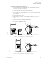
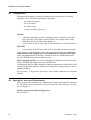
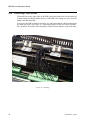
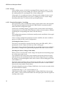
2.2 Manufacturer’s declaration
A manufacturer’s declaration, as set out in the Machinery Directive 89/393/EEC,
Annex II B is supplied with all deliveries to EU and EEA countries. See Figure 1.
Säkerhet-svetsutr_eng.fm
7
Welding equipment
a3(tiff)
Safety
Figure 1 Manufacturer’s declaration.
8
Säkerhet-svetsutr_eng.fm
Welding equipment
Safety
2.3 Installation
•
When unpacking, check that all the equipment has been supplied and that it
has not been damaged during transportation. Damaged or broken equipment
can mean a safety risk.
•
Remove all packaging after unpacking to avoid the risk of fire. Leave suitable packaging for recycling.
•
Ensure that the equipment, or parts of it, do not tip or fall over when
unpacking or transporting.
•
“Secure” the load before it is taken from the packaging.
•
Make sure that cables do not rest against sharp edges. If possible run cables
in cable trenches to prevent the risk of tripping.
•
Welding fumes and any gases that may be formed or used when welding
can be hazardous to inhale. It is the responsibility of the purchaser/user that
satisfactory extraction devices are installed and used. Follow the directives
of respective countries.
•
The purchaser/user is also responsible that sufficient lighting is provided
over the workplace. As a suggestion, lighting can be integrated in the fume
extraction equipment.
•
If possible use environment friendly shielding gas, for example, MISON
(AGA) and environment friendly vegetable based oil for spatter cleaning.
2.4 Usage
All personnel working with the equipment must have sufficient training in its use
and be well-conversed with applicable safety directives. Incorrect use can result in
personal injury and damage to the equipment.
Ensure the working area is in order before the system is commissioned. If faults are
discovered on or in system these should be rectified before start-up.
Call skilled personnel or the system manager if your own knowledge is insufficient
to implement the requisite actions.
All protection and safety equipment must be fitted to the station before it is used.
This should be especially observed in connection with maintenance and service
routines.
Safe working methods must be employed to prevent injury. Safety equipment must
not be disconnected, bypassed or in any other way modified so its protectiveness
ceases.
Ensure that no one is within the risk area before resetting the safety equipment and
before the station is started.
Use personal safety equipment, e.g. welding helmet with welding glass, protective
clothing and gloves to protect the eyes and skin from injuries caused by rays and
burning. Also protect others by setting up suitable screens and drapes.
Do not touch the welding gun’s gas nozzle or the hot work piece directly after
welding. Use protective gloves.
Säkerhet-svetsutr_eng.fm
9
Welding equipment
Safety
If possible, carry out spatter cleaning in a special area where welding spatter and
oil can be collected. Welding spatter and oil on the floor brings about a risk of slipping.
2.5 Fire risk
There is a risk of fire in connection with welding. Ensure the area around the workplace is free from inflammable material. Clean the area regularly. Follow local
directives for welding.
Make sure all connections in the welding current circuit are correctly tightened.
Bad connections will result in an inferior welding result and the risk of fire. Cables
that have not been dimensioned correctly, i.e. too light, can also bring about a fire
risk due to overheating.
2.5.1 Fire fighting
Use carbon dioxide (CO2) to extinguish equipment if it should start to burn.
Note that in the event of a fire there is a great risk of gas cylinders exploding.
Follow local safety directives relating to the handling of gas cylinders.
2.6 Risk of electric shock
Do not mix up the phase and ground cables when connecting the equipment to the
mains supply.
Do not touch ”live” parts of the equipment with bare hands or with damp gloves or
clothes.
Welding wire is connected to voltage during the welding process even before the
arc is ignited.
Welding circuits should not be grounded bearing in mind the risk of the ground
cable being damaged by prohibited welding current paths.
The welding circuit must not be broken while welding is in progress.
2.7 Maintenance and service
There is still a risk of injury even if the equipment’s mains supply has been
switched off.
Warning for a falling robot or falling load on the manipulator when the
brakes are released.
Warning for protruding welding wire and welding spatter coming from the
gun when servicing.
Do not look directly into the gun; use protective glasses.
10
Säkerhet-svetsutr_eng.fm
Welding equipment
Technical Description
3 Technical Description
The welding equipment A140E/A314E/A324E-L (E for Extended range) is
adapted for the control from the IRB 140/1400/2400 robot with the S4Cplus control system. Together with the AW software in the robot and the PIB process interface the system has the following characteristics:
•
Large working area,- With an optical tachometer, with a high frequency
resolution in the wire feed unit, a stable wire feed is obtained, across the
speed range: 0.3 m/min – 30 m/min.
•
Accuracy - The transfer of information between the robot and the welding
equipment is done in series in the form of numerical data by way of a CAN
bus, guaranteeing great accuracy.
•
Programmability - All programming of the welding process is done from
the robot programming unit.
•
Safety - The welding equipment is fitted with sensors for the supervision of
the welding process. If an error occurs an error message is displayed on the
robot programming unit.
•
Flexibility - The transfer of programmable configuration data enables the
adaptation to different power sources and feed units.
The welding equipment consists of the A140E/A314E/A324E-L_PIB wire feed
unit and one of the following power sources:
- LAW350R/500R (not valid for A140E, FlexArc Compact)
- LAF 635R (not valid for A314E/A324E-L, FlexArc Compact)
- RPA 400
- LRB 400, integrated in Control cabinet,- ARCITEC-system
- LRC 430 - ARCITEC-system (not valid for A140E, FlexArc Compact)
The following options are available to the Welding equipment:
- welding gun set
- joint locator, "Smartac"
- torch cleaner "TC"
- wire cutter
- automatic TCP-gauging "BullsEye"
- TSC Torch Service Center consisting of:
Torch cleaner "TC", Wire cutter and automatic TCP-gauging "BullsEye"
Teknbeskr_eng.fm
11
Welding equipment
Technical Description
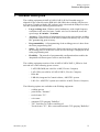
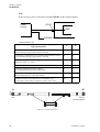
Robot Welding System
"Flexible Interface" for power sources RPA, LAW and LAF.
A140E/A314E
A324E-PIB
Power
source
RPA
LAW
LAF
S4Cplus
CANbus
Device Net
gas/water
sensor
Option
TC
BullsEye
collision
sensor
PIB
Option
Smartac
Control cabinet
Figure 2 Overview of "Flexible Interface" connections.
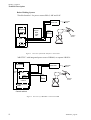
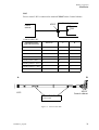
"ARCITEC" with integrated power source LRB400, or separate LRC430
A140E/A314E/
A324E-PIB
S4Cplus
CAN
bus
gas/water
sensor
PIB
Option
Smartac
Option
TC
Bullseye
collision
sensor
CANbus
Power source
LRB
Control cabinet
Figure 3 Overview of "ARCITEC" connections LRB.
12
Teknbeskr_eng.fm
Welding equipment
Technical Description
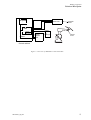
A140E/A314E/
A324E-PIB
S4Cplus
gas/water
sensor
PIB
Option
Smartac
CANbus
Option
Power
source
LRC
TC
Bullseye
collision
sensor
Control cabinet
Figure 4 Overview of "ARCITEC" connections LRC.
Teknbeskr_eng.fm
13
Welding equipment
Technical Description
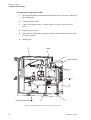
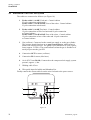
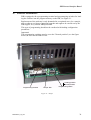
Incorporated components A140E
1
Wire feed mechanism mounted and fitted with a Euro-socket for connecting
the welding gun.
2
Connections for media.
3
Cable for the power source - control cabinet, valid for separate power
source.
4
Separate power source
5
Power source, integrated in separate cabinet, placed under the control cabinet (not in picture).
6
Welding gun
6
Bobin
1
Control cabinet
2
OCE
5
TSC Torch Service Center
3
4
Figur 5 Robot Welding System with separate power source.
14
Teknbeskr_eng.fm
Welding equipment
Technical Description
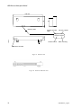
Incorporated components A314E/A324E-L
1
Wire feed mechanism mounted on the robot arm and fitted with a Eurosocket for connecting the welding gun.
2
Attachment for the wire feed mechanism and cables.
3
Hoses for gas, water and compressed air, as well as cables for signal and
power supplies.
4
Cable for the welding current.
5
Cable for the power source - control cabinet, valid for separate power
source.
6
Separate power source (with Flexible Interface).
7
Power source, integrated in cabinet.
3
4
1
2
6
503597A1
5
Figure 6 Robot Welding System with separate power source.
3
4
1
2
Arcitec
7
Figure 7 Robot Welding System with integrated power source.
Teknbeskr_eng.fm
15
Welding equipment
Technical Description
3.1 Wire feed system A140E/A314E/A324E-L
There are two options of wire feed systems: bobbin or marathon pac.
A314E/A324E-L should be used for gas arc welding.
3.2 Wire feed system A314E/A324E-L
The wire feed system A314E/A324E-L meets Arc Welding & Application Equipment’s recommended layout setup. This means the robot has a full working area
within a section of ±150° for A314E/A324E-L, around axle 1. Great care should be
exercised outside of this sector, e.g. when programming otherwise the welding
equipment can be damaged.
It is intended to be mounted directly on the robot IRB 1400/IRB 2400L, which
results in a short cable bundle and a good wire feed, furthermore, a smaller floor
area is required.
16
Teknbeskr_eng.fm
Welding equipment
Technical Description
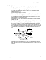
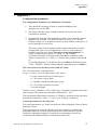
3.2.1 Wire feed unit
Wire is fed using two pairs of feed rollers, see Figure 8, which are linked to each
other. The power from the motor is transferred to the rollers via a pinion on the
motor shaft. The two upper rollers (1) are spring-loaded.
The pressure between the upper and lower rollers can be adjusted individually
using an adjuster screw (2).
All rollers are fitted with sleeve bearings.
The lower feed rollers (3) have grooves for two different wire diameters. The rollers are turned so that the marking for the required wire diameter is facing forwards.
The motor (4) is of a permanent magnetised type and is equipped with an optical
tachometer meter for accurate speed control.
An inlet guide (5) is fitted when the marathon pac is used. The nozzle is locked
using the screw (6).
When the bobbin is used, the wire liner is fitted directly to the feed mechanism and
is locked by screw (6). The wire can roll off of the bobbin when the feed mechanism stops at a high wire feed speed. To rectify this, the preset value on the brake
hub is changed to 5 kpcm (= 0,5 Nm), by turning the knob until the arrows align
with each other (locked bobbin position). The springs on each side of the knob are
turned synchronously inwards to increase the braking effect. If the wire feed speed
is too high so that the adjustment has no effect then the marathon pac ought to be
used.
2
4
1
5
1
j500084
6
3
Figure 8 Wire feed unit.
To guarantee proper wire feed the grooves in the feed rollers must be cleaned at
regular intervals. The wire used should be as clean as possible as filth can give rise
to slippage.
Teknbeskr_eng.fm
17
Welding equipment
Technical Description
Replacement - Repair
When refitting the drive motor in the event of replacement or repair of the motor
the motor shaft must be centered in relation to the two feed rollers, using the
centering device (art. no. 500 332-001) in order to avoid wear as regards teeth and
bearings.
Dismantling
1
Remove the two drive rollers.
2
Dismount the driving gear and the three Allen screws. The drive motor can
now be lifted out.
The remounting is performed in the reverse order, excepted the use of the
centering device.
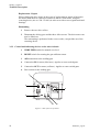
3.2.2 Control and indicating devices on the wire feed unit
1
WIRE FEED switch for manual wire feed.
2
RESET switch for resetting the gun collision sensor.
3
AIR connection to the welding gun.
4
Connection IN for water (blue hose). Applies to water cooled guns.
5
Connection OUT for water (red hose). Applies to water cooled guns.
6
Euro-socket for the welding gun.
1
2
5
j500084
6
4
3
Figure 9 Side of the wire feed unit.
18
Teknbeskr_eng.fm
Welding equipment
Technical Description
3.2.3 Main data
Wire diameters
Max. wire feed unit
Permitted ambient temperature
0.8 mm - 1.6 mm
30 m/min.
0ºC - +40ºC
3.3 PIB Process Interface Board
The PIB is an I/O unit particularly adapted for welding robot systems and handles
the communication between the robot control system and the welding equipment.
The PIB is described in detail in chapter 6 of this manual.
Teknbeskr_eng.fm
19
Welding equipment
Technical Description
20
Teknbeskr_eng.fm
Welding equipment
Installation
4 Installation
4.1 Configuration of Welding Equipment
4.1.1 Flexible Interface/ ARCITEC (LRB/LRC)
On delivery the equipment is configured according to applicable configuration data
which are stored on the disk that comes with the delivery. The data can be read and
modified by way of the robot programming unit. See chapter 6.5.
For the definition of configuration data, see “Appendix 1” on page 57.
The following files on the installation disk contain configuration data for the welding equipment:
Rpa_Fhp.cfg
Law_Fhp.cfg
Lrb_Fhp.cfg
Laf_Fhp.cfg
Explanation: Configuration data for power source RPA and
wire feed unit A140E/A314E/A324E-L_PIB
Explanation: Configuration data for power source LAW and
wire feed unit A140E/A314E/A324E-L_PIB
Explanation: Configuration data for power source LRB/LRC
and wire feed unit A140E/A314E/A324E-L_PIB
Explanation: Configuration data for power source LAF and
wire feed unit Welding equipment_PIB
In case these configuration data must be reloaded, proceed in one of the following
ways:
•
Roboot the robot: The original configuration will be restored.
•
Manual loading using the programming unit: Print out the configuration
data from the disk supplied. This can be done using an ordinary PC and a
word processing program (for example Notepad in Windows). If required,
the configuration data can now be adjusted according to the printout by way
of the programming unit.
•
Loading from the configuration disk: Executed by way of the robot
instruction System Parameters\IO Signals\File⇒ "Add or Replace
Parameters\ "file"
Important!
As the disk is unique for the equipment supplied it should be stored in a safe place.
The program number indicated on the disk corresponds to the configuration in
question, and should be referred to in case of service matters regarding the function
of the welding equipment.
Installation_eng.fm
21
Welding equipment
Installation
4.2 Installation of the wire feed system
The cables are connected as follows (see Figure 10):
1
Feeder cable 1, A140E, Feed unit - Control cabinet
23-pole connection at both ends
Feeder cable 1, A314E/A324E, Foot of the robot - Control cabinet
23-pole connection at both ends
2
Feeder cable 2, A140E Feed unit - Control cabinet
12-pole connection at Wire feed unit and 19-pole connection
at Control cabinet.
Feeder cable 2, A314E/A324E Foot of the robot - Control cabinet
12-pole connection at foot of the robot and 19-pole connection
at Control cabinet.
3
Gas (red hose). Connected to the central gas supply or to the gas cylinder.
The pressure guard functions as an open contact device, which means it
makes with a rising pressure. The guard is precalibrated to 0.2 bar (equivalent to approx. 5 l/min.). The guard indicates when the gas is finished or if
an object prevents the gas flow.
4
Connection OUT for water (red hose).
5
Connection IN for water (blue hose).
6
Air in (PVC hose D14/8). Connected to the compressed air supply, system
pressure, approx., 6 bar.
7
Welding cable 95 m2.
8
Wire guide input for bobbin and Marathon Pac.
Finally connect the current cable from the wire feed unit to the power source.
1
8
7
j5000843
2
6
5
4
3
Figure 10
22
Installation_eng.fm
Welding equipment
504806a01
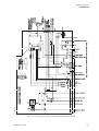
Installation
Figure 11 Circuit diagram, Wire feed unit A140E/A314E/A324E-L_PIB
Installation_eng.fm
23
Welding equipment
Installation
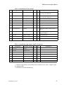
Kopplingstabell kablar/ Connection table, cables
Control cabinet
XP106
Feed unit
Circuit diagram
Figure 11
PIB
TB6
FEED 1
Feeder Cable 1, A140E/A314E/A324E-L
Signalbeskrivning/
Signal Description
A
B
Färg
Colour
Gun Reset
B
B
Vit
White
Gun Crash Sensor
N
N
Brun
Brown
Current Sensor
P
P
Grön
Green
Water Flow Sensor
D
D
Gul
Yellow
Gas Flow Sensor
F
F
Grå
Gray
Tacho +
K
K
Rosa
Pink
Tacho - (Encoder Tacho
input)
L
L
Blå
Blue
Manual Wire Feed
A
A
Röd
Red
24 VDC Supply
J
J
Svart
Black
0 VDC (24 VDC) / Encoder
Tacho Common
C
C
Violett
Violet
Motor Temperature
M
M
Grå/Rosa
Grey/Pink
Auxiliary Motor
E
E
Röd/Blå
Red/Blue
ADM Tacho (+) Encoder
Tacho input
G
G
Vit/Grön
White/Green
ADM Tacho (-)
H
H
Brun/Grön
Brown/Green
+5V Encoder Tacho
R
R
Vit/Gul
White/Yellow
Spare (not used)
S
S
Gul/Brun
Yellow/Brown
503281A2
A140E
Feed unit
EXT. FEED 1
A
xxx xxx xxxx
XP106
Control cabinet
B
503281A1
A314E/A324E-L
IRB-CS
Foot of the robot
Figure 12 Feeder cable 1, A140E/A314E/A324E-L.
24
Installation_eng.fm
Welding equipment
Installation
Control cabinet
XP105
Feed unit
Circuit diagram
Figure 11
PIB
TB5
FEED 2
Feeder Cable 2, A140E/A314E/A324E-L
Signalbeskrivning/
Signal Description
A
B
Färg
Colour
Motor +
A
A
Vit
White
Motor +
B
B
Brun
Brown
Motor +
C
C
Grön
Green
Motor -
D
D
Gul
Yellow
Motor -
E
E
Grå
Gray
Motor -
H
H
Rosa
Pink
PneumaticSpatter Cleaning
(42/115VAC)
G
G
Blå
Blue
Gas Valve (42/115 VAC)
K
K
Röd
Red
Arc Voltage Gun
M
M
Svart
Black
Smartac 1
L
L
Violett
Violet
Aux Motor Supply (42/115
VAC phase)
J
J
Grå/Rosa
Grey/Pink
Aux Motor Supply (42/115
VAC common)
F
F
Röd/Blå
Red/Blue
503284A2
A140E
Feed unit
EXT. FEED 2
xxx xxx xxxx
A
XP105
Control cabinet
B
503284A1
A314E/A324E-L
IRB-CP
Foot of the robot
Figure 13 Feeder cable 2, A140E/A314E/A324E-L.
Installation_eng.fm
25
Welding equipment
Installation
4.3 Connection of Power Sources
LAW
Power source LAW is connected to terminal XP107 on the Control cabinet.
Control cabinet
XP107
Power
source
PIB
TB3
Control cable LAW
Signalbeskrivning/
Signal Denomination
Part/Core
A
B
42V AC
1
B
A
Start PS
2
F
B
Ref.
3
K
C
0V
4
L
D
Weld-/Weld Object
5
N
F
Arc Voltage Gun
6
H
G
NC
SH
Shield
A
503215A1
B
XP107
Control cabinet
LAW
EXT. CABLE PS LAW
xxx xxx xxxx
Figure 14 Control cable LAW
26
Installation_eng.fm
Welding equipment
Installation
RPA
Power source RPA is connected to terminal XP107 on the Control cabinet.
Control cabinet
XP107
Power
source
PIB
TB3
Control cable RPA
Signalbeskrivning/
Signal Denomination
Part/Core
A
B
0V
wh (par/pair 1)
B
B
Start PS
bu (par/pair 1)
E
C
Ref.
wh (par/pair 2)
-
A byglas med D/
A bridged with D
0V
or (par/pair 2)
A
D byglas med A/
D bridged with A
WELD-/WELDOBJ.
SH
F
NC
XS WELD
SH
B
503218C1
A
XP107
Control cabinet
RPA
XS WELD
EXT. CABLE PS RPA
503218-8XX
xxx xxx xxxx
Figure 15 Control cable RPA.
Installation_eng.fm
27
Welding equipment
Installation
LAF
Power source LAF is connected to terminal XP107 on the control cabinet.
Control cabinet
XP107
Power
source
PIB
TB3
S(ENSE cable) wire to weld object
Control cable LAF
Signalbeskrivning/
Signal Denomination
A
B
Startingång: Anslutning för yttre slutande kontakt mellan A och B./
Start: External closing contact between A and B.
A
A
Startingång: Anslutning för yttre slutande kontakt mellan A och B./
Start: External closing contact between A and B.
B
B
Referensingång för Svetsspänning: (0 - 4.09 V)/
Reference input: (0 - 4.09 V)
C
C
0 V, (Referens) / (Reference common)
D
D
Bågspänningsåterföring från svetspistol./
Arc Voltage feed back from the welding gun.
G
G
Svetsminusanslutning för fogsökare Smartac./
Weld-/Weld object for seam finder Smartac.
H
F
Skärmen anslutet via kondensator till strömkällans hölje./
The shield is connected by a capacitor to power source case.
NC
NC
A
559486a01
B
XP107
Control cabinet
LAF
Ext.Cable,PSLAF
xxx xxx xxxx
Figure 16 Control cable LAF.
28
Installation_eng.fm
Welding equipment
Installation
LRC
Power source LRC is connected to terminal XP107 on the Control cabinet.
Control cabinet
XP107
Power
source
PIB
TB3
Control cable LRC
Signalbeskrivning/
Signal Denomination
Part/Core
A
B
Spare
1
D
1
Spare
2
E
2
Ext. enable
3
F
3
Ext. enable
4
C
4
Welding minus (OKC)
5
M
5
Welding measure - (Ext.)
6
J
6
Welding measure + (Ext.)
7
H
7
SH
SH
PE
A
503354A1
B
XP107
Control cabinet
LRC
EXT. CABLE PS LRC
xxx xxx xxxx
Figure 17 Control cable LRC
Installation_eng.fm
29
Welding equipment
Installation
4.4 Installation of accessories
4.4.1 Cooling unit OCE 2
(included in welding gun set PKI 500R and Binzel WH 455D)
1
Connect the cable bundle to the cooling unit as follows:
- Red water hose to the cooling unit’s return connection IN.
- Blue water hose to the cooling unit’s feed connection OUT.
- Air hose to the compressed air supply.
- Gas hose to the gas cylinder.
2
Connect the cooling unit’s mains cable as follows:
- For LAW, RPA, LAF: The mains cable is connected to terminal
A202X3:5,6 in the control cabinet.
- For LRB, LRC: The mains cable is connected to terminal
A204:X202:10,11 in the control cabinet.
3
Fill the cooling unit with water and any anti-freeze (for detailed information
refer to the OCE 2 manual). Check the flow in the welding gun by opening
the cooling unit’s return hose connection IN until water comes in.
4
If the water guard is ordered afterwards, the strap in the wire feed unit must
be removed before the guard can be used. This is done as follows:
- Unscrew the strap By1 on the terminal in the wire feed unit between connections 2 and 4.
30
Installation_eng.fm
Welding equipment
Installation
4.4.2 Torch Cleaner TC
For LAW, RPA, LAF ARCITEC: Mechanical torch cleaner TC is connected to terminal XP108 on the control cabinet.
Control cabinet
XP108
TSC/TC
PIB
TB4
Cable -Torch cleaner
Signalbeskrivning/
Signal Denomination
Färg
Colour
A (TC96)
A(BINZEL)
B
24V DC
Vit
White
4
1
1
0V DC
Brun
Brown
2&8
3&4
2
Lubrication
Grön
Green
11
7
3
Cleaning
Gul
Yellow
10
6
4
Wire cutter
Grå
Grey
1
NC
5
Cleaning Finished
Rosa
Pink
7
2
6
Bullseye
Blå
Blue
16
10
7
Shield
SC
SC
NC
NC
PE
A
503293A01
B
TC
EXT. CABLE TCH-CLEAN
xxx xxx xxxx
XP108
Control cabinet
Figure 18 Cable - Torch Cleaner
Installation_eng.fm
31
Welding equipment
Installation
32
Installation_eng.fm
Welding equipment
Maintenance
5 Maintenance
Disconnect the mains supply and (if possible) secure the switch before starting
work on the equipment.
In some cases however, it is necessary to work with the mains supply switched on,
special care and safe working methods must be used.
5.0.1 Wire feed unit
Make a visual inspection of the equipment and correct errors, if any, for reliable
operation.
1
Purge the inside of the feed unit as necessary by compressed air at reduced
pressure.
2
Clean the grooves in the feed rollers and the bore of the outlet nozzle.
3
The wire conduit should always be purged by compressed air when changing the wire and as necessary. When worn out change the wire conduit.
4
Use filler wire free of impurities.
5
The bearings of the motor and the gear box are permanently lubricated maintenance-free.
After maintenance (also installation and service) on the equipment, check the following before starting up:
•
that no tools have been forgotten
•
that fixtures and work piece are secured well
•
that all parts and guards are replaced
•
that functions are correct.
Note! Only use genuine spare parts and extra accessories recommended by
ABB.
Underhåll-svetsutr_eng.fm
33
Welding equipment
Maintenance
34
Underhåll-svetsutr_eng.fm
PIB Process Interface Board
6 PIB Process Interface Board
6.1 General
The PIB is an I/O unit with integrated wire feed regulator communicating directly
with the ABB robot control system S4Cplus for control and monitoring of the
robot welding.
The configuration is done in the same way as for a standard I/O unit.
The PIB characteristics are determined by the transfer of configuration parameters
for power sources and feed units.
The communication with the robot computer is serial and is maintained by way of
a CAN bus.
The PIB I/O connections are grouped together for direct cable connection to units
such as power sources, wire feed units, gun cleaners, sensors, etc. See Figure 19.
LEDs for
functional status
TB6
TB11
Wire feed unit
TB3
TB5
Wire feed unit
Power source
TB1
Power supply and interlocking
TB2
TB4
Gun cleaner
16
NS
196,0
MS
CAN bus
0
501700A1
1
Jumper TB9
257,0
72,5
Euro connector, 32-pole
"Add-on board"
D-sub
Switch
for loading of program
for loading of program
Figure 19 Dimensions and Terminal Designations.
PIB-M2001_eng.fm
35
PIB Process Interface Board
6.2 Voltage Version - Power Supply - Article Number
PIB is available in two voltage versions:
- for feed units with voltage supply to the final stage of the feed unit regulator of max. 42V AC/ 10A, article no. 501 700-880.
- for feed units with voltage supply to the final stage of the feed unit regulator of max. 115V AC/ 3.5A, article no. 501700-881.
They are marked Low voltage or High voltage. See Figure 20.
Warning! Connecting 115V AC to the low-voltage version of PIB will destroy the
PC board.
Personal safety
The high-voltage version:
A protective earth conductor (min. 2.5 mm2) shall be connected between the
upper PIB metal bar and the protective earth bar of the robot cabinet before
the unit is switched on.
There are transformers available for the particular voltage. They are to be connected to terminal XT21 for 230V AC/ 3.15A in the robot cubicle.
See the section Transformers on page 52.
6.3 Program Versions
PIB includes two program versions. Which program version is active is determined
by the TB9 jumper. See Figure 21.
1
For robot systems from S4Cplus with Flexible (see section 6.5) and ARCITEC-LRB/LRC the TB9 jumper shall be open (removed or parked on one
of the pins).
The jumper in this position supports:
- The transfer of configuration data from the robot programming unit.
- Automatic transfer of configuration data from the robot when
changing PIB.
2
For the robot system S4C with ARCITEC/LRA the TB9 jumper must be
closed.
- The transfer of configuration data according to point 1 is not supported.
- The configuration for ARCITEC/LRA is done on delivery.
Note:
When a complete system is delivered the TB9 position is determined.
All PIB equipment delivered separately or as spare part are pre-configured for
ARCITEC/LRA and wire feeder A314 (jumper TB9 closed) on delivery.
For use together with S4Cplus the jumper is removed and the parameter transfer
takes place according to point 1.
36
PIB-M2001_eng.fm
PIB Process Interface Board
6.4 Marking and Version Handling
Figure 20 shows the location and disposition of the article and manufacturing numbers. This marking indicates the hardware version of PIB – not the software one.
The software version is indicated under the configuration menu in the programming unit for the robot as a non-editable four digit number. The number is automatically updated when the software version is changed.
Extra marking
PIB15sv
High voltage/
Low voltage
ABB product
High voltage 006
Low voltage 005
Version number
5601 006-0200
ABB Welding
0000002 990825
501 700-881
Testing date
Serial number
Article number
501 700-880, Low voltage
501 700-881, High voltage
Figure 20 Marking and Version Handling.
PIB-M2001_eng.fm
37
PIB Process Interface Board
6.5 Configuration
Programmable parameters enable the adaptation to different types of welding
equipment. The configuration parameters determine:
- the control properties
- the scale factors
- the offset values
- the max. and min. values, etc.
Flexible
•
A manual standard power source enabling remote control by way of analogue references and with the on/off function, for example LAW 350R/
500R, RPA 400, LAF, Miller Delta Weld, etc.
•
A wire feeder of the DC type with AC/DC tachometer as speed feed-back.
ARCITEC
•
A wire feeder of the DC type with AC/DC tachometer as speed feed-back.
These factors are listed and their values can be edited under the menu: Misc\System\Parameters\IO signals\Types⇒Units\PIB-name (=configured IO-name)
on the programming unit of the robot. Modified values are automatically transferred to the PIB board when starting the robot.
When changing the PIB, - Previous configuration parameters stored in the robot
will be automatically transferred to the new PIB card.
Configuration data for ABB’s standard welding equipment are included in the AW
system configuration diskettes, which can be ordered according to the price list for
standard products.
See Appendix 1; Configuration parameters, where all the parameters are listed and
defined.
6.6 Options for Increased Functionality
PIB is prepared for connection of a supplementary board increasing the functionality. The board is to be connected to a 32-pole connector of the Euro type. See Figure 19 on page 35.
Smartac (joint search and tracking device):
See section 6.15.
38
PIB-M2001_eng.fm
PIB Process Interface Board
6.7 Software Maintenance
PIB is equipped with a programming terminal and programming switches for loading the software into the program memory on the PIB, see Figure 21.
Replacement of the software is only demanded in exceptional cases, for example,
after a software revision or functional upgrade and ought to be carried out by the
PIB supplier or by trained ABB personnel.
This type of programming should not be confused with loading configuration
parameters.
Important!
The programming switches must be set to the "Normal position" (see the figure
below) in order for the PIB to work.
Loading position
Programming terminal
Jumper TB9
Normal position
Programming switch
Figure 21 Jumper.
PIB-M2001_eng.fm
39
PIB Process Interface Board
6.8 Service and Programming Aids
6.8.1 CAN-Assist, Art. no. 502 800-880
PC based tool that in Passive Mode allows listening to the CAN-bus traffic in the
Weld system during the current process.
In Master Mode, with the connection to the robot master disconnected, the I/Ofunction in the different units in the system can be activated, parameters loaded or
changed.
CAN-Assist is supplied as a package with hardware and a CD containing software
and documentation.
6.8.2 Indication unit for PIB, Art. no. 505 100-001
Tool that is connected to the 32 way Euro connector on the PIB.
The unit uses light emitting diodes to show the CAN-bus status of the inputs and
outputs on the PIB. The analogue display shows the value of an analogue channel,
the wire feed speed or reference for the weld voltage. Channel selection is made
using 3 push buttons.
6.8.3 Smartac with indication unit, Art. no. 505 100-002
Same as above, but with combined Smartac function.
6.9 Diagnostics – Error Handling
The PIB is fitted with two light-emitting diodes according to the DeviceNet specification, see Figure 19 on page 35.
One of the diodes has the designation NS (Network Status) and indicates the function of the CAN bus. The other one has the designation MS (Module Status) and
indicates the PIB function.
Correct function is indicated by a green light coming on and incorrect function by a
red light. During the initiation phase, which can take a few seconds, the light of the
diodes changes.
Exception: On ARCITEC LRA/S4C (jumper TB9 made) does not indicate NS
while MS indicates the status as set out above.
During software execution on the robot (start, stop and current execution) the continuous transfer from PIB of the function status from the PIB as well as from the
weld process takes place via the sensors connected to the PIB.
In the event of an error on PIB an error message is given to the robot programming
unit as a warning to call action, see the table below. The weld process is not interrupted.
If the error concerns process supervision (shield gas, weld current) the weld process is interrupted with the error message "Arc Supervision".
Error messages are acknowledged by pressing OK.
40
PIB-M2001_eng.fm
PIB Process Interface Board
When the error is corrected a message appears to confirm the this. If a two errors
occur at the same time and the first error is not corrected this is shown during the
next restart. If the second error is corrected the previous error returns during the
next start. If both errors are eliminated at the same time only the last one is confirmed.
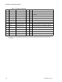
Table Error messages
From PIB with version numbers -503. -0702 and from -1100 and higher the
number of error messages is limited to the following:
80001
2 PIB error, warning
Analog outputs outside limits
Check the limits in ctrl.conf.part motor max/min Speed
and max Volt.
80001
4 PIB error, warning:
Digital Output overloaded in PIB, fatal error
Check the output connections. Reset with power switch.1
80001
9 PIB error stop:2
Motor drive transistor overtemp in PIB.
Check friction in wire conduit.
80001
11 PIB error, warning
Supply voltage 24 Volt on PIB too low.
Check incoming power supply.
1. The overloaded (short-circuited) output is switched off by its overcurrent protection.
The weld process is only interrupted if the process supervision is affected.
The function resumed when the power supply to the PIB is switched on after the power supply to the
PIB has first been cut and the overload eliminated.
2. The error does not cause a stop. The text will be changed to "PIB error, warning" in later robot software versions.
PIB-M2001_eng.fm
41
PIB Process Interface Board
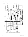
6.10 Connecting Cable Shields
The metal bar on the upper side of the PIB is provided with holes for the fitting of
2 cable clamps coming with the delivery of the PIB. The clamps are to be screwed
tightly onto the metal bar.
In order for the PIB to function correctly it is important that the shield connections
are made precisely. See Figure 22. This mainly applies to the two cables from the
wire feed unit. If possible, they should be routed at some distance from each other.
Figure 22 Shielding.
42
PIB-M2001_eng.fm
PIB Process Interface Board
6.11 Safety
6.11.1 Personal Safety
Moving parts which according to the EU machinery directives might cause personal injury are interlocked via the robot holding device and emergency circuit.
Such functions are manual wire feed and mechanical cleaning of the gun.
Figure 23 on page 50 shows the build-up of the PIB interlocking system.
If national regulations require that also the power source shall be interlocked, the
interlocking system can be completed by a relay opening the control circuit of the
power source.
On manual wire feed via the welding gun or the push-button of the feed unit, the
wire can be fed without holding down the holding device up to max. 6 metres per
minute. The speed will increase as long as the push-button is activated. For speeds
higher than 6 m/min the holding device must be held down. For ARCITEC/LRA
the speed is constant - 5 m/min.
Manual wire feed: Appendix 2, Possibilities and limitations.
6.11.2 Machine Safety - Collision Sensor
The PIB is designed to be used with a welding gun with collision sensor.
In normal status the sensor is to supply 24V DC to the PIB input TB6.2.
The collision sensor controls the Run Chain relay in the PIB. The relay is of the
two-pole type and is integrated in the general stop chain (G-stop) of the robot. In
normal status the relay is active.
When the collision sensor is activated the Run Chain relay opens, resulting in
opened G-stop chain, leading to quick-stop of the motion due to the fact that the
robot goes from operation mode to stand-by mode. The error message G-stop
comes up on the robot programming unit. The message remains until it has been
acknowledged by way of the OK button.
To enable putting the robot into operation again the G-stop chain must first be
closed.
If the gun has occasionally been out of position but has sprung back again, the Gstop chain closes and the robot is fit for use again.
If the gun remains in the wrong position, for example after having collided with the
weld object, the fixture, etc., the robot must be moved in order to make the gun
spring back. On the front of the ABB wire feed units A-314 there is a spring-back
push-button (reset) for this purpose.
Reset Function
When the collision sensor is reset the PIB microprocessor activates the Run Chain
relay and closes the G-stop chain. It is then possible to put the robot into service
again, by using the robot joystick to manoeuvre the robot to make the gun spring
back, resetting the collision sensor in closed position. The reset function is automatically acknowledged.
PIB-M2001_eng.fm
43
PIB Process Interface Board
The start of the running of the program is blocked until acknowledged. Trying to
start before acknowledgement will result in the Run Chain relay opening and the
G-stop chain breaking. The reset procedure must then be repeated.
To prevent the PIB remaining in the reset function - due to circuit interruption, for
example - and to ensure that a further collision will stop the robot, the reset time is
limited to 1 minute. After that the G-stop is interrupted again and the reset procedure must be repeated.
What is said above applies both to manual running of the robot and to running by
way of the program. When running the robot by way of the program there appears
an additional error message, expressly indicating that the collision sensor has been
activated.
The error messages are:
Message 1:
PIB error, warning:
Welding Gun has crashed. If gun still crashed, reset from wire
feed.
Move robot with joystick. Not allowed to start prg.
Message 1 comes up in combination with a G-stop with the welding gun remaining
in the wrong position.
Message 2:
PIB error, warning:
Welding Gun has been reset.
Message 3:
PIB information:
Gun back to normal position after being down.
Messages 2 and 3 will come up after restart in this order. If the collision is of short
duration and the gun breaks only momentarily and springs back again, message 1
will not be displayed. Messages 2 and 3 will be displayed, however.
6.11.3 Machine Safety - Electronics
PIB is designed to withstand the short-circuiting of the outputs and overloading of
the motor regulator.
The overloaded output is switched off. The function resumes when the power supply is switched on again after the power supply to the PIB has first been cut and the
overload eliminated.
The motor regulator is protected by a current limiter on the drive stage.
Units connected to the PIB are also protected as the max. and min. data can be configured, for example, max. reference for the power source, max. speed of the connected wire feed unit.
As evident from the section Diagnostics – Error Handling on page 40 an error
message is displayed to demand a proposed action.The weld process is not interrupted.
44
PIB-M2001_eng.fm
PIB Process Interface Board
6.12 Signal Connections
See also Figure 19 on page 35 and Figure 23 on page 50.
TB stands for Terminal Block.
6.12.1 Table - Signal Connections
TB1 - Power Supply and Interlocking
Function,
Voltage
Designation
Out
In
Explanation
1
Motor Supply
AC
Power supply for the motor regulator, interlocked
42V max. for PIB 501700-880
115V max. for PIB 501700-881
2
Motor Supply Common
AC
Zero, power supply
3
Supply solenoid valves
AC
Power supply not interlocked for
solenoid valves and push feed unit
4
Logic supply
28V AC
Power supply for logic circuits
5
Logic supply common
0V AC
Zero, power supply for logic circuits
6
Ground
0V DC
Ground, screen
7
I/O 24 VS
DC
8
Manual Wire Feed out
24V DC
9
Run Chain A1
Relay contact
Run Chain A
10
Run Chain A2
Relay contact
Run Chain A
11
Run Chain B1
Relay contact
Run Chain B
12
Run Chain B2
Relay contact
Run Chain B
13
24V Ext
24V DC
PIB-M2001_eng.fm
x
x
x
Interlocked 24V DC
Control signal for closing the interlocking contactor
24V DC (see Figure 23 on page
50)
45
PIB Process Interface Board
TB2 - CAN bus Connection
Designation
Function, Voltage
Out
In
Explanation
1
Sys 0V
DC
System 0 (=Robot I/O noll)
2
CAN Low
Serial comm.
CAN Low *
3
Ground
DC
Ground, screen
4
CAN High
Serial comm.
CAN High *
5
Sys 24V
DC
6
0V
DC
0V for addressing
7
NA 0
Jumper, NC=active
Binary addressing, not connected to TB2:6=1
8
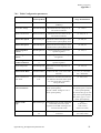
NA 1
Jumper, NC=active
Binary addressing, not connected to TB2:6=2
9
NA 2
Jumper, NC=active
Binary addressing, not connected to TB2:6=4
10
NA 3
Jumper, NC=active
Binary addressing, not connected to TB2:6=8
11
NA 4
Jumper, NC=active
Binary addressing, not connected to TB2: 6=16
12
NA 5
Linkage, NC=active
Binary addressing, not connected to TB2: 6=32
x
System 24 V (=Robot I/O 24V)
*. Terminator resistor 120 Ohm to be fitted between TB2/2 and TB2/4 if PIB is the farthest off I/O unit in
the system. See recommendations regarding the connection of terminator resistance in the robot product manual.
46
PIB-M2001_eng.fm
PIB Process Interface Board
TB3 - Connection to Power Source
Designation
Function, Voltage
Out
In
Explanation
1
Start Power Source A
Closing contact
x
Control relay for power source
(or cooling fan, ARCITEC)
2
Start Power Source B
Closing contact
x
Control relay for power source
(or. cooling fan, ARCITEC)
3
Weld ref.
Analog 0-15 V
x
Reference for welding voltage
4
Ref. Common
Analog common
x
Reference zero
5
Induct. Ref
Analog 0-15 V
x
Reference for setting of the inductance
6
Weld Object
Analog
7
Arc Voltage Gun
Analog
8
Arc Voltage object
Analog
9
24 V Ext
Supply voltage
x
For external relay
10
0V
Supply voltage
x
For external relay
11
NC
x
Sensing the welding voltage on weld
object*
x
Return the welding voltage to power
source
Sensing the welding voltage on weld
object for PDM**
Not connected
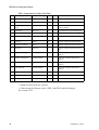
TB4 - Connection to gun cleaner and TCP detector
Designation
Function, Voltage
Out
In
Explanation
1
24V DC
Supply
x
2
0V DC
Supply, zero
x
3
Lubrication
Digital 24V DC
x
Lubrication for cleaning reamer
4
Cleaning
Digital 24V DC
x
Cleaning reamer
5
Wire Cutter
Digital 24V DC
x
Cutting the wire
6
Cleaning finished
Digital 24V DC
x
Cleaning finished
7
Bulls Eye
Digital 24V DC
x
TCP search stop
* Common connection to the welding object and the power source, negative pole
for Smartac/PIB.
** PDM=Process Data Monitoring
PIB-M2001_eng.fm
47
PIB Process Interface Board
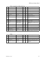
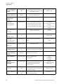
TB5 - Connection 1 to Wire Feed Unit
Designation
Function, Voltage
Out
In
Explanation
0-60/0-170V DC
x
Motor voltage
x
Motor voltage
1
Motor +
2
Motor -
3
Pneum Spatter Cleaning
42V AC
x
To solenoid valve for Pneumatic
spatter cleaning
4
Gas Valve
42V AC
x
To solenoid valve for shielding gas
5
Arc Voltage Gun
0-70V DC
6
Smartac 1
40V DC
x
Search voltage for Smartac Sensor
1
7
42V AC
Phase
x
Supply voltage for Push feed unit
8
42V AC Common
Zero
x
Supply voltage for Push feed unit
9
Smartac 2
40V DC
x
Search voltage for Smartac Sensor
2**
10
Spatter Cleaning A
Closing contact
Alternative parallel function for
TB5:3*
11
Spatter Cleaning B
Closing contact
Alternative parallel function for
TB5:3*
12
Gas Valve A
Closing contact
Alternative parallel function for
TB5:4*
13
Gas Valve B
Closing contact
Alternative parallel function for
TB5:4*
14
Tig Mode
24V DC
x
Option
15
Feed Reverse
24V DC
x
Control signal for motor reversing
16
HF Ignition
24V DC
x
Option
x
Arc voltage feed-back**
* Adapted contact protector required.
** When using the Smartac sensor 2 TB5:5 and TB5:9 shall be bridged.
See section 6.15.2
48
PIB-M2001_eng.fm
PIB Process Interface Board
TB6 - Connection 2 to Wire Feed Unit
Designation
Function, Voltage
Out
In
Explanation
1
Gun reset
24V DC
x
Resetting the collision sensor
2
Gun Crash
24V DC
x
Collision sensor
3
Current Sense
24V DC
x
Welding current sensor
4
Water Flow
24V DC
x
Water flow sensor
5
Gas Flow
24V DC
x
Gas flow sensor
6
NC
NC
7
Encoder TG INPUT
DC Puls
x
DC- or AC-tacho/input for encoder
tacho
8
Man. Wire Feed
24/DC
x
Manual wire feed
9
+ 24 V
Supply voltage
x
Supply voltage
10
0V
Supply voltage
x
Supply voltage/ common for encoder tacho
11
Temp PTC
Analog
12
Aux Motor
24V DC
13
PDM Tacho +
AC/DC
x
Tacho for Process data monitoring
14
PDM Tacho -
AC/DC
x
Tacho for Process data monitoring
15
+ 5V alt + 15V
DC
x
Function, Voltage
Out
Bridged with TB 6/10
x
x
Temperature sensor in wire fed unit
Control signal for Push feed unit
Supply voltage for encoder tacho
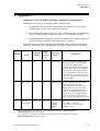
TB11
Designation
In
Explanation
1
Weld Current A
Analog
x
Shunt connection for PDM
2
Weld Current A
Analog
x
Shunt connection for PDM
3
HF Ignition
24V DC
x
Indication of HF ignition, Option
4
Smartac sense detect
24V DC
PIB-M2001_eng.fm
x
Alternative for sens. detect. via
CAN-bus
49
PIB Process Interface Board
502540s4c+
6.12.2 Elementary Diagram - Power Supply and Interlocking
Figure 23 Elementary Diagram, Power Supply, Safety and Interlocking.
50
PIB-M2001_eng.fm
PIB Process Interface Board
6.13 Technical Specification
6.13.1 Mechanical Data
Dimensions: 257x196x72.5 mm
Weight: 2.1 kg
Enclosure class: IP 20
6.13.2 Electrical Data
Power supply: See Figure 24 on page 52 - Transformers.
Digital outputs:
Continuous load/output: max. 350 mA.
Total output load: max. 1.6 A, < 70°C.
Tripping of overload protection per output: 370 mA.
Remark: Regarding capacitive load > 0.05 uF a temporary overload can arise at
the start causing the overload protection to trip. If this occurs a current-limiting
resistor must be connected in series with the connected load.
Digital inputs 24V DC:
Incoming voltage, switch on: 15 to 35V.
Incoming voltage, switch off: -35 to +5V.
Incoming impedance, 4 kohm, resistive.
42V AC outputs: Max. current: 1A at < 70°C.
Relay outputs: Max. voltage: 250V AC.
Max. current: 10 A.
Note: Sparc protection has to be externally connected.
Analog outputs: Outgoing voltage: 0 - 15 V, < = 100 mA, < = 70°C.
6.13.3 Environmental Data
Temperature data:
Storage
Cold 40° C, 16h
Heat +70° C, 16 h
Change – 40° C / +70° C, 2 cycles
Operation
According to
+5° C, 2 h
IEC 68-2-1
+70° C, 2 h
IEC 68-2-2
IEC 68-2-14
EMC: (ElectroMagnetic Compatibility) According to standard EN 50199.
LVD: (Low Voltage Directive) According to LVD standard EN 60204.
PIB-M2001_eng.fm
51
PIB Process Interface Board
6.14 Transformers
Article No. 501 714-001/-002
brun/brown
gul/yellow
röd/red
42V 7.5A
Uo=43.5V
230V
50Hz
28V 3A
Uo=28.9V
gul/yellow
vit/white
0-230V
0-28V
0-115V
115V 2.7A
Uo=118.9V
orange
vit/white
28V 3A
S2
Uo=28.9V
vit/white
gul/yellow
orange
S1
28V 7.5A
svart/black Uo=28.9V
P1
HV
-002
R=2,2 Ohm 10W
R=2,2 Ohm 10W
230V
50Hz
LV
-001
High Voltage
Low Voltage
gul/yellow
0-28V 0-28-42V
501714c1
0-230V
Marking
vit/white
Figure 24 Transformers.
52
PIB-M2001_eng.fm
PIB Process Interface Board
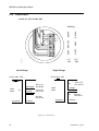
6.15 SmartacPIB
6.15.1 General
Smartac/PIB is a further development of the ABB joint search
device Smartac. Mechanically
and electrically it is integrated
with the ABB welding interface
PIB (Process Interface Board).
smartac
The unit has two sensor inputs,
which can be activated one at a
time or simultaneously.
Figure 25
smartac-pib
The unit is a so-called "Add-on"
unit and is connected to the PIB
by way of a 32-pole connector
of the Euro type, see Figure 30.
Figure 26
The search properties of Smartac/PIB are determined by two adjustable parameters, Voltage Valid Limit and Sensor Detection Sensitivity. They are transferred
from the robot together with other PIB configuration data. See point 6.14 Configuration Parameters.
The search properties can thereby be adapted to the existing circumstances of the
search circuit.
PIB-M2001_eng.fm
53
PIB Process Interface Board
6.15.2 Sensors
In the welding system A314/A324 containing PIB, the input for sensor 1 is connected to the gas cup of the welding gun, whereas sensor input 2 is connected to
the welding nozzle for searching by way of the welding wire.
Using sensor 2 it is usually necessary to disconnect the welding circuit to avoid
current diversion through the power source resulting in too low search voltage.
Searching with sensor 2 is only used for special applications.
6.15.3 Function Description - Searching
The search of the joint is usually done using a search routine in the robot program.
The following description assumes that the ABB Flexible Automation signal
names and robot configuration apply.
In deliveries containing Smartac, programs for the search routine and configuration parameters are pre-loaded. When Smartac is delivered as an option, a diskette
containing the corresponding data comes with the delivery.
Note.
The configuration parameters for Smartac usually must be modified to fit the application in question.
In the event the configuration parameters must be modified, the same conditions
apply as for PIB. See the section Configuration.
Activating the Sensor (Sensor 1)
The sensor is activated by a message from the robot to the PIB, doSE1_SEL=1,
applying the search voltage to the gas cup of the welding gun.
The search voltage connected between the gas cup and the object to be searched is
generated by a voltage source galvanically separated from other current circuits.
Checking the Sensor (Voltage Valid Limit)
When a sensor is activated the search voltage will depend on the insulating properties of the open search circuit.
Low insulation value between the sensor and the parts having electrical contact
with the object to be searched will reduce the search voltage, due to for example
the passage of current through the water when a water-cooled welding gun is used,
soot formation, etc.
Increased contact resistance due to oxide layers, oil film, soot, etc. in combination
with decreased search voltage makes it more difficult to achieve reliable contact
between the sensor and the search object.
Using the adjustable parameter Voltage Valid Limit a level can be set under which
the search shall not continue.
Configuration range: 0 – 40 V in increments of 1V.
If the present search voltage is higher than the Voltage Valid Limit, the message
diSe_Valid=1 will be sent from the PIB to the robot giving the robot the signal for
carrying on the search.
54
PIB-M2001_eng.fm
PIB Process Interface Board
Sensitivity (Sensor Detection Sensitivity)
The adjustable parameter Sensor Detection Sens determines the sensitivity of the
sensor. Configuration range: 0-25.5V in steps of 0.1V.
The Smartac trigger level is locked by the message doSE_REF=1 from the robot
according to the following:
Trigger level = the present search voltage - the Sensor Detection Sens value.
Under normal conditions reliable search is achieved using values > = 1V.
Detection
When during the search the gas cup gets into contact with the search object the
sensor input is exposed to voltage drop.
If the voltage drops below the trigger level the PIB will send the search stop message diSE1_DET=1 to the robot, and the co-ordinates of the search object can be
registered.
See Appendix 4 on page 65, "Optimising the search circuit".
6.15.4 Delivery
Smartac is delivered as Smartac complete, article no. 503500-880, consisting of:
- Smartac unit, see Figur 27 on page 56
- Software, contained in the system diskette when a complete system is
delivered, and in a separate diskette when Smartac is delivered separately
- User’s Guide with program description and examples.
- Smartac with indication unit, 505 100-002. See Figur 28 on page 56.
6.15.5 Technical Data
Accuracy: Max. deviation ± 0.25 mm at a search speed of 20 mm/sec.
Marking: See Figur 27.
Mechanical Data
Weight: 0.220 kg
Dimensions: 22x65x185 mm (see Figur 27)
Enclosure class: IP 20.
Electrical Data:
Max. search voltage: 40V
Max. search current: 4.3 mA.
Environmental data: See point 6.16.3
PIB-M2001_eng.fm
55
PIB Process Interface Board
Delivery data
53
65
185 mm
Product number
ABB
Version number
15
503400A1
22
xxxxxxx-xxxx
xxxxxxx xxxxxx
Serial number
Date of testing
10
ABB article number
Figur 27 Smartac unit.
Figur 28 Smartac indication unit
56
PIB-M2001_eng.fm
Welding equipment
Appendix 1
7 Appendix 1
Configuration parameters
The configuration parameters are defined for 3 demands:
1
They should be an integer in order to simplify handling in the
microprocessor in the PIB.
2
The integer should be large enough so that the desired accuracy and
resolution are obtained.
3
Programming from the robot should be possible to be expressed in actual
quantities, for example, 21.4 m/min for the wire speed, 32.2 V for the
welding voltage, etc. A multiplier with one or more indexes to the power of
ten is required in several cases:
The setting range for the parameters and a number that defines what the
configuration value is to be multiplied by in order to express the true
relation is stated in the column "Parameter range/denomination" in
"Table Configuration parameters" on page 59 . For example:
If "MotorCurrentLim" is defined to the value 80, the definition means
"Motor Current Limit {0 ...100}0.1 A" that the max permitted current is 8
A.
If "ProcEquipRefConv" is defined to the value 8260, the definition means
{1000 ...30000}E-3 that the relation Output voltage/Reference is 8.260 etc.
The conversion factor for the wire feed with AC-tacho:
The conversion factor is obtained from
k0=g x n x 100/(π x D x 60) [Hz/m/min x 100], where:
- k0 is the conversion factor for tacho type 0
- g = The gearbox’s gear factor
- n = Number of tacho periods/motor speed
- D = Feed roller’s diameter in metres
- 100 is the multiple.
In those cases k0 should be >65535, Tacho type 2 should be configured and at the
same time the conversion factor should be defined as k2 = k0/2.
The maximum permitted tacho frequency is 27000 Hz, which limits the maximum
theoretical feed speed to Vmax = (π x D x 60 x 27000/(g x n)[m/min]
Control parameters for the wire feed
The control parameters are: Feed Forward factor, Motor Regulator P-factor, Motor
Regulator I-factor
These parameters are tested for the wire feed units supplied as standard and
adjustment should be avoided. Modifications can result in incorrect speed or
instability. Adjustment ought to be carried out in consultation with service
personnel from ABB Automation Technology Products AB.
Appendix1eng_Konfigurationsparametrar.fm
57
Welding equipment
Appendix 1
Transfer of parameters between the robot and PIB,
The configuration parameters are sent from the robot’s system parameter memory
to the PIB each time the system voltage is switched on. If the parameters are equal
to those already in the PIB no writing to the PIB is carried out.
If the parameters in PIB differ to those being sent from the robot, for example, with
the replacement of PIB, the parameters that differ in PIB are written, which means
that the new PIB gets the same configuration as the previous one1.
In order for the new parameters to apply the system must be restarted.
If the parameter "System definition", is changed, which involves a change to the I/
O type for PIB, the parameter transfer takes place in two steps. First the
redefinition of the new I/O unit in the robot takes place, which requires a restart.
During the next start the transfer to the PIB takes place and in order for the
parameter to apply to the PIB another restart of the robot is required. Thus, in this
case, two restarts are required. The second time it is sufficient with a "warm boot"
of the system.
Table - Configuration parameters.
The table contains all the parameters defined for PIB. They are shown and can be
edited from the robot’s programming unit.
All parameters are not implemented as standard. Parameters that are implemented
and which must have the correct value to function correctly are marked by an
asterisk and bold type.
1. Note that the jumper TB9 should be open.
58
Appendix1eng_Konfigurationsparametrar.fm
Welding equipment
Appendix 1
7.0.1 Table Configuration parameters
Parameter name
Parameter name
in teach pendant
Parameter behavior
Parameter
range/ denomination
Software Revision
SoftwareRevison
Current software revison
(readonly)
-
Motor Max Voltage
MotorMaxVoltage
Maximum allowed voltage for the
DC-motor connected.
{0...110} V
Motor Current Limit
MotorCurrentLim
Maximum allowed current for the
DC-motor connected.
{0...100} 0.1 A
*Motor Max Speed
MotorMaxSpeed
Maximum allowed setting for motor
speed in motor speed quantity units
{0...500} 0.1
*Motor Min Speed
MotorMinSpeed
Minimum allowed setting for motor
speed in motor speed quantity units
{0...500} 0.1
*Motor Regulator
P-factor
MotorRegPFactor
Proportional factor of the motor
speed PI regulator.
{0...100} %
*Motor Regulator
I-factor
MotorRegIFactor
Integrating factor of the motor speed
PI regulator.
{0...100} %
*Motor Regulator
Feedforward-factor
MotorFeedForwar
d
Feedforward factor of the motor
speed PI regulator.
{0...100} %
Motor Temp Limit
MotorTempLimit
Maximum allowed temperature for
the motor.
{0...255} °C
*Motor Brake Ratio
MotorBreakRatio
Defines the duty cycle of the brake
transistor .
{0...255} 0 = No brake.
255 = Full brake
Motor Control Error
Time Limit
MotorCtrlErrTime
Lim
Defines the maximum allowed time
for difference between motor speed
set value and actual value before
setting the alarm
{0...255} 1/10 s
*Motor Tacho
Conversion Factor
MotorTachoConv
For AC: 100 Frequency in Hz for 1
motor speed quantity.
For DC: 10000 Voltage in V for 1
motor speed quantity.
*Motor Tacho
Type
MotorTachoType
Determines type of tacho connected
and used by the motor speed
regulator of the PIB. Valid types are
AC-tacho and DC-tacho
{0,1}
0 (AC-tacho)
1 (DC-tacho)
2 (Fast AC-tacho)
MotorTachoDCOff
set
Motor speed offset for DC-tacho
connected
{-1000...1000} 0.01 m/min
(Or r/min, l/min)
Motor DC Offset
Appendix1eng_Konfigurationsparametrar.fm
{0...65535}
AC (tacho type 0) : 0.01 Hz
/ motor speed quantity
AC fast (tacho type 2): 0.02
Hz / motor speed quantity
DC (tacho yype 1): e-4 V /
motor speed quantity
59
Welding equipment
Appendix 1
*Process Equipment
Reference Convers.,
Flexible
ProcEquipRef
Conv
Conversion factor between the
process quantity in the set value and
the reference voltage
{1000...30000}e-3 Process
quantity / Vref
*Process Equipment
Reference Offset, Flx.
ProcEquipRef
Offset
Offset value for the process. Given
in process quantity units.
{0...1000} 0.1 V
*Process Equipment
Max Reference
Voltage
ProcEquipMaxRef Maximum allowed reference
voltage.
{0...1000} 0.1 V
Process Data
Monitoring Speed
Conversion Factor
PdmSpeedConv
For AC: 100 Frequency in Hz for 1
motor speed quantity motor speed.
For DC: 10000 Voltage in V for 1
motor speed quantity motor speed
Process Data Monitoring
Tacho Type
PdmTachoType
Type of tacho used for true process
quantity measurement
{0,1}
0 (AC-tacho)
Process Data Monitoring
Tacho DC Offset
PdmTachoDCOffs
et
PDM DC tacho offset
{-1000...1000} 0.01 motor
speed quantity
{0...65535}
AC: 0.01 Hz / motor speed
quantity
DC: e-4 V / motor speed
quantity
Process Data
Monitoring Current
Shunt Conversion
PdmShuntConv
Process Data Monitoring
Shunt Offset
PdmShuntOffset
PDM Shunt offset
{-32000...32000} mA
*Sensor Detection
Sensitivity, Smartac
SensorDetectionSe
ns
Defines the search voltage drop for
detection of contact with workpiece
{0...255} 1/10 V
*Sensor Search
Voltage Valid Limit,
Smartac
SensorSearchVolt
ValidLim
Defines the lowest allowed search
voltage for start of search.
{0...40} V
*System Definition
SystemDefinition
Defines the PIB system
configuration
(0,1)
0 (Flexible)
1 (Arcitec)
*Machine
Identification code,
ARCITEC
MotorMachineID
The motor machine identification for
the wirefeed range of the current
wirefeed motor. Only valid for
Arcitec system
{0..255}
According to wirefeed
motor cable
Inductance Reference
conversion
OptProcEquipRef
Conv
Conversion factor between the
process quantity in the set value and
the reference voltage
(1000...30000)e-3 Process
quantity / Vref
Inductance Reference
Offset
OpProcEquipRefO Offset value for the process. Given
ffs
in process quantity units.
60
Scale factor for the shunt used in
PDM.
{0...65535} e-5 mV/A
15000
(0...1000) 0.1 V
Appendix1eng_Konfigurationsparametrar.fm
Welding equipment
Appendix 2
8 Appendix 2
Manual wire feed with PIB and S4Cplus, possibilities and limitations:
Manual wire feed can be carried out in three different ways:
1
By pushing in the non-locking push button for manual wire feed on the
welding gun or on the front of the wire feed unit.
2
By activating the function Manual wire feed from the robot’s programming
unit in test mode under: Program window\Arcweld\Manual wirefeed.
3
By activating the robot output doFEED in combination with the setting of a
speed reference in aoFEED_REF under the I/O window..
The table below shows the characteristics and differences between the methods.
Observe comment 3 below regarding the limitation in functionality for method 3.
Method
Speed1
Ramping
function
Safety
pad
pressed
in
Setting the
reference
Explanation
1
Max. 6m/min
yes
no
automatically
The arc weld function "Manual Wire
feed" in the robot is called from PIB.
The robot input diMAN_WF is
activated. The robot activates the output
doFEED with a reference in aoFEED
that increases as a function of the time
the wire feed button is pressed in. The
function is active as long as the button is
pressed in. The speed is limited to max.
6 m/min by PIB2.
2
Max. 9m/min
yes
yes
automatically
The arc weld function "Manual Wire
feed" is called from the robot’s
programming unit. The robot input
diMAN_WF is activated. The robot
activates the output doFEED with a
reference in aoFEED that increases as a
function of the time the Manual feed
button is pressed in. The function is
active as long as the button is pressed in.
3
The full
speed range
no
yes
yes,
manually
Limited
validity3
The reference range is expressed as
0 - 0.5 m/s (0 - 30 m/min).
The function is active as long as
doFEED is set to 1.
1. Speed: If the speed range is limited by the configuration parameters MotorMaxSpeed or
MotorMinSpeed the limitation applies.
For ARCITEC it also applies: If the speed range is limited by the configuration parameter
MotorMachineID the limitation applies.
Appendix2eng_Man trådmatning.fm
61
Welding equipment
Appendix 2
2. Limitation for reasons of personal safety.
3. Note: The reference only applies as long as aoFEED is not changed by any other function: The
methods 1 and 2 or execution of a program with another value.
After using methods 1 or 2 the reference is reset.
62
Appendix2eng_Man trådmatning.fm
Welding equipment
Appendix 3
9 Appendix 3
System accuracy: verification and trimming possibilities.
Wire feed: Feed unit A140E/A314E/A324E-L
A check of the wire feed unit’s accuracy ought to be carried out by measuring the
motor tachometer’s pulse frequency and not by measuring the fed wire and time
measurement in order to avoid errors, due to wire slip and errors during starting
and stopping.
The right speed presupposes that the friction in the wire conduit system is not so
high that the wire feed regulator reaches the current limit (10A).
The frequency signal is available across terminal TB6 : 7 (5 V pulse) and 10 (0 V)
on PIB, or between terminals 13/4 (5V pulse) and 12/4 (0V) in the wire feed unit.
The measurement is appropriately carried out using a multimeter with frequency
measurement, for example, Fluke 87 or the like. If problems occur due to switchdisturbances from the motor current a capacitor, max 0.02 µF, can be connected
across the measurement clips.
If an oscilloscope is used it should be galvanically separated from ground in order
to prevent disturbances on the tacho signal that can affect the function of the wire
feed unit.
The table below shows the relation between the frequency and wire speed for
A314E.
The wire feed unit's configuration factor: 20650.
The wire feed unit's pulse amplitude: 4.5 - 5V
f = v * G * N /(pi *D * 60)
where:
f
v
G = 24
N = 60;
D = 0.037 m
Frequency, Hz
Wire speed, m/min.
The gear's gear ratio
Number of periods per turn of the motor
Feed roller's diameter (contact diameter for the welding wire.)
m/min
Hz
m/min
Hz
m/min
Hz
0.5
103
10.5
2168
20.5
4233
1.0
206
11.0
2271
21.0
4336
1.5
310
11.5
2374
21.5
4439
2.0
413
12.0
2478
22.0
4542
2.5
516
12.5
2581
22.5
4646
Appendix3eng_Frekvenstabell.fm
63
Welding equipment
Appendix 3
m/min
Hz
m/min
Hz
m/min
Hz
3.0
619
13.0
2684
23.0
4749
3.5
723
13.5
2787
23.5
4852
4.0
826
14.0
2891
24.0
4955
4.5
929
14.5
2994
24.5
5059
5.0
1032
15.0
3097
25.0
5162
5.5
1136
15.5
3200
25.5
5265
6.0
1239
16.0
3304
26.0
5368
6.5
1342
16.5
3407
26.5
5471
7.0
1445
17.0
3510
27.0
5575
7.5
1549
17.5
3613
27.5
5678
8.0
1652
18.0
3716
28.0
5781
8.5
1755
18.5
3820
28.5
5884
9.0
1858
19.0
3923
29.0
5988
9.5
1961
19.5
4026
29.5
6091
10.0
2065
20.0
4129
30.0
6194
Power source (does not apply to ARCITEC)
When using PIB to control the power source with an analogue reference (Flexible
Mode) the reference characteristics are determined by the parameters:
ProcEquipRefConv (gain), ProcEquipRefOffset (offset) and
ProcEquipMaxRef.(Max 48 V DC):
When replacing PIB or the power source the weld result can deviate from previous
result depending on the tolerances in the analogue circuits in PIB and the power
source.
By adjusting one or both of the two first-mentioned parameters above it is possible
to eliminate the difference and avoid comprehensive modification to the weld
program.
If a power source has no base voltage (reference is linear from 0 V) for example,
LAW, LAF and others, the gain is adjusted by ProcEquipRefConv.
On a power source that has base voltage (output voltage at ref. 0V) for example,
RPA and others, adjustment of both parameters is necessary. With several
iterations where Offset is adjusted at the lowest current weld value and the gain is
adjusted at the highest current weld value, the weld result is trimmed to acceptable
similarity to the result before the replacement.
The adjustment is appropriately made in small increments.
For example, if the welding voltage is assessed to be 5% too low, the configuration
value is reduced by a value that is < 5%, if the welding voltage is too high, the
configuration value is increased by < 5%, etc. Note - inverted conditions.
The procedure is repeated until the desired result is achieved.
The procedure is suitable if similarity between several power sources is required.
It is recommended that changes are noted for the PIB or the power source that have
caused the change if the standard configuration is not used.
64
Appendix3eng_Frekvenstabell.fm
Welding equipment
Appendix 4
10 Appendix 4
Smartac; Optimising the search circuit
The function of the Smartac is, to a great extent, dependent on the insulation
characteristics of the search circuit.
1
Water cooled gun
Distilled water or demineralizized water should be used for the best
function.
The welding gun should be filled with the water when searching. In other
words: The cooling pump should be switched on.
The above also applies when the Smartac is commissioned and the
configuration parameters for SensorSearchVoltLim and
SensorDetectionSens are determined.
2
Elimination of false search stop due to current transfer between
sensors 1 and 2.
Problems: A search stop occurs when the non active sensor attains contact
with the workpiece before the active sensor.
For example: The search stop occurs when the welding wire (sensor 2)
attains contact with the workpiece before sensor 1 (gas cup) although sensor
2 is not activated (or connected) 1
Reason: Even with relatively good insulation (>50 kOhm) between the gas
cup and welding wire there is a current transfer that will give a voltage drop
on the active sensor when the passive sensor touches the workpiece which,
if the sensitivity is too high, will give a search stop.
The reason is the high internal resistance in the sensing circuit in Smartac.
The above applies analogously for sensor 2 when it is used as the active
sensor (even if the welding circuit is isolated by a contactor).
Actions:
- It is checked when searching that a search stop does not occur if the
inactive sensor makes contact with the workpiece.
Which, for example, for sensor 1 is simply performed by connecting a
weld wire to the workpiece during the search phase and analogously for
sensor 2 connect the gas cup to the weld object during the search phase.
If a search stop occurs the configuration for "SensorDetectionSens" is
changed to a lower sensitivity (which means higher value).
Where appropriate, it may be necessary to first lower the level for
approved search voltage "SensorSearchVoltLim".
The robot system must be restarted when the configuration has been
changed (warm boot).
1. Strapping between TB 5:5 and TB 5:9 on PIB not carried out.
Appendix4eng_Smartac_sökfel.fm
65
Welding equipment
Appendix 4
- Perform searching in this way so that the risk of the wrong sensor
coming into contact first with the workpiece is minimised.
66
Appendix4eng_Smartac_sökfel.fm
504 869-102