1
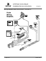
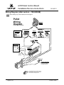
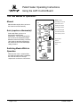
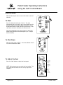
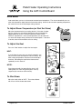
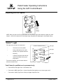
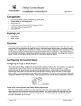
AVR Pellet Control Board
Installation/Service Instructions
250-00011
Compatibility
•
Avalon Newport PS and Newport Bay PI (Avanti PS & PI)
•
Avalon Astoria PS and Astoria Bay PI
•
Lopi Pioneer PS and Pioneer Bay PI (Heritage PS & PI)
•
Lopi Yankee PS and Yankee Bay PI
Packing List
•
Control Board (AVR Design)
•
Molex Jumper
Overview
The new AVR control board is the next generation control board that is compatible with all pellet stoves and
inserts, large and small manufactured from 1997 to today. Circuitry on the board allows it to be programmed
for either the large or small pellet heaters (these heaters use different voltage settings). See “Configuring the
Control Board“ for details. It also includes a diagnostic feature that allows a service person to diagnose a
fault without having to inspect the wiring or components. The indicator lights on the control board will display
a fault code after a fault has been detected. This allows the service person to determine which component
caused the fault. See “Diagnostic Codes” for details. NOTE: the new wiring harness (250-00017) is required
to utilize this feature.
Configuring the Control Board
Configuring for Large or Small Heaters
The control board is initially configured for the large heaters (Astoria and Yankee models). To change the
configuration the control board must be in the off position plugged into a cold stove, (no lights or running
components) with the jumper molex removed (see the illustration below). In this condition press and hold the
manual auger button down and press both fan up and fan down arrow keys at the same time. All heat output
lights will flash. One flash denotes the large pellet heater configuration. Two flashes denote the small pellet heater
configuration (Newport and Pioneer models). Repeat pressing the keys until the correct configuration is obtained.
250-00012
Using this Control Board with Older Wiring Harnesses
When the control board is installed on an older wire harness the 4 pin molex jumper plug on the back of the
control board next to the stock wire harness must be installed. This jumper replaces the diagnostic wires (see
“Wiring Diagram”) that are present on the new wiring harness. The control board will work normally, but the
diagnostic capabilities will not function.
Page 1 of 2
Printed 1/24/06
AVR Pellet Control Board
Installation/Service Instructions
250-00011
Technical Notes for Operation
The new pellet control board is essentially the same as our old board. The biggest difference between them is
that buttons were used in place of knobs on the heat and fan controls.
Make sure to give the home owner the “Pellet Heater Operating Instructions” if you are replacing an
older board (the final 4 pages of this instruction sheet). It contains the new operating instructions for
this control board.
A few changes were made to accommodate the new control board. The start up cycle indicator on the old
board illuminates all heat output indicator lights to show the unit is in a start-up cycle and adjusting the heat
setting knob would not change them. On the new board to enable adjusting the run settings during start-up we
made the start-up indicator the blinking #1 heat output light. If the #1 heat output light is blinking the board is
in a start-up mode and the blower and auger outputs can not be adjusted. The run settings the unit will go to
after start-up are displayed on the heat output indictor. These settings can be adjusted any time during start
up by pushing the up or down heat buttons on the panel. When the fan setting is adjusted up or down the
heat output indicators will turn off and the fan setting will display.
Another feature we added to the control board is a manual auger feed. This button can be used to prime and
empty the auger or speed the initial delivery of pellets to the burn pot. All start-up timing remains the same
and the stove will still self prime the auger tube – this option allows the operator an additional option. It is not
needed for normal operation.
All voltage outputs and feed rates remain the same as the old board. There is a difference in respect to the
auger on/off times. The auger timing was changed to shorten the interval between pellet drops to the burn
pot. For example, on low the auger used to turn for 3 seconds and remain off for 13 seconds, for this same
condition this control board turns the auger for 2.5 seconds and remains off for 10.7 seconds. This produces
the same amount of time the auger is turning and not turning but gives a steadier flame height and less
incidental outages on low.
Page 2 of 10
Printed 1/23/06
AVR Pellet Control Board
Installation/Service Instructions
250-00011
Diagnostic Codes (Qualified Service Personnel Only)
•
Fault and #2 (LOW) Light Flash = Flow Switch Fault
•
Fault and # 4 (MED) Light Flash = System Snap Disk Fault (pellets run out & stove goes cold)
•
Fault and # 6 (HIGH) Light Flash = Safety or Hopper Snap Disk Fault
DISCONNECT POWER BEFORE SERVICE
H
E
A
T
O
U
T
P
U
T
HIGH
REMOTE
# 6 Light
# 4 Light
AUTO
MED
LOW
MANUAL
# 2 Light
AUGER
FAULT
Flow Switch Fault
Fault light and #2 heat indicator blinking.
This fault code indicates pressure/flow switch opened or broke its electrical connection during operation.
Likely causes:
•
•
•
•
•
•
Pinched, cracked or broken pressure tubing.
Plugged tubing nipple on blower housing.
Heavy ash build up in the exhaust fan housing,
Faulty wiring, bad or broken connection of flow switch gray wires.
Weak or bad combustion blower
Faulty pressure switch.
Page 3 of 10
Printed 1/23/06
AVR Pellet Control Board
Installation/Service Instructions
250-00011
Diagnostic Codes (Qualified Service Personnel Only) - Continued
System Snap Disk Fault
Fault light and #4 heat indicator blinking.
This fault code is caused by a heat sensitive switch that tells the control board if the appliance is hot or cold.
During operation if the unit runs out of pellets or looses its fire this switch will communicate to the control
board that the stove is getting cold. The control board will shut off the auger functions and initiate a twenty
minute combustion fan safety cool down. Another condition that will trigger this fault code is a failed start.
When the appliance is started the control board initiates a 30 minute timer, if the appliance is cold at the end
of this 30 minute start up timer the control board will indicate a #4 fault and initiate a 20 minute combustion
fan cool down.
Likely causes:
•
•
•
•
Unit ran out of pellets.
Fire went out during operation.
Unit was cold at the end of a start cycle (fire did not light).
Faulty snap disk.
Safety or Hopper Snap Disk Fault
Fault light and #6 heat indicator blinking.
This fault code is caused by the safety or hopper snap disk registering an over-heated appliance during
operation. The control board then shuts down the auger and the convection and combustion blower will run at
maximum output for a 40 minute safety cool down cycle. The only way to stop this cool down is to unplug the
appliance to reset the control board.
Likely causes:
•
•
•
•
•
•
•
Faulty snap disk
Corroded, loose or broken Snap Disk wiring.
Failed, plugged or blocked convection blower.
Reduced air flow into the motor compartment such as blocked air vents on panels or doors.
Missing refractory.
Improper fuel type.
Unauthorized parts used in the pellet feed system.
Page 4 of 10
Printed 1/23/06
AVR Pellet Control Board
Installation/Service Instructions
250-00011
Wiring Diagram (new, 2005 version – 250-00017)
Pellet
Wiring
Diagram
Exhaust
Blower
Flow Switch
White
Large Pellet
Stoves Only
Safety Snap
Disk
Male
Female
Hopper
Snap Disk
Red
White
Igniter
ge
Black
Convection
Blower
Hot (fuse)
White
Ground
Gr
Black
White
Orange
Common
ee
n
Black
Screwed
to
Baseplate
2
4
6
8
an
Red
Or
Power Cord
1
3
5
7
Gray
AAAAA
AAAAA
AAAAA
AAAAA
AAAAA
AAAAA
AA
AAAAA
AAAAA
AAA
Auger Motor
Key to Quick
Connects
Gray
(wiring harness 250-00017)
3
7
5
1
6
4
2
8
System Snap
Disk
ite
Wh
Bla
ck
c
Bla
Bro
k
Bro
wn
Re
Brown
NOTE: some
models use
quick-connects.
d
Bro
wn
Brown
wn
O
1
3
g
ran
e
ay
Gr
Or
an
ge
ay
Gr
2 4
Page 5 of 10
Printed 1/23/06
AVR Pellet Control Board
Installation/Service Instructions
250-00011
Wiring Diagram (older version – 100-00393B)
NOTE: Wire coloring may not be identical to this diagram.
Pellet
Wiring
Diagram
Exhaust
Blower
(wiring harness 100-00393B)
Hopper
Snap Disk
White
Key to Quick
Connects
AAAAA
AAAAA
AAAAA
AAAAA
AAAAA
AAAAA
A
Large Pellet
Stoves Only
Auger Motor
Male
Female
Purple
Red
Blue
Black
Red
White
Igniter
Flow Switch
Safety Snap
Disk
Power Cord
Common
White
Black
Convection
Blower
Hot (fuse)
Gr
White
Ground
ee
n
1
3
5
7
2
4
6
8
Black
Screwed
to
Baseplate
ite
3
7
Wh
5
1
6
4
2
8
Bla
ck
ack
Bl
Bro
Bro
wn
Re
Brown
d
Bro
System Snap Disk
wn
Brown
NOTE: some models
use quick-connects.
wn
NOTE: Make sure the jumper plug is
installed when using the AVR control
board with this wiring harness.
Page 6 of 10
Printed 1/23/06
Pellet Heater Operating Instructions
Using the AVR Control Board
The Two Modes of Operation:
DISCONNECT POWER BEFORE SERVICE
Manual
Manual mode requires the user to turn
the heater on and off manually.
Auto (requires a thermostat)
Auto mode allows you to use a
thermostat to control room
temperature. The stove automatically
turns on when the temperature drops
below the thermostat setting. Once the
stove reaches operating temperature,
the stove then runs at the heat output
setting selected.
modulating remote, this
H
E
A
T
O
U
T
P
U
T
H
E
A
T
HIGH
REMOTE
AUTO
MED
LOW
UP
Whenever the stove is switched from
one mode to another while in operation,
the stove will enter the "start-up"
sequence for a minimum of 20 minutes.
Page 7 of 10
light will come on to
indicate the remote is
controlling the heater.
MANUAL
These indicator lights
AUGER
are used to determine
FAULT
which mode you are in.
AUTO
OFF
MANUAL
Use the mode
switch to
DOWN
MANUAL
determine the
mode.
START
UP
Switching Modes While in
Operation
NOTE: if using a
F
A
N
MANUAL
DOWN
AUGER
TM
TRAVIS INDUSTRIES
HOUSE OF FIRE
Printed 1/23/06
Pellet Heater Operating Instructions
Using the AVR Control Board
Manual Mode
Manual mode requires the user to turn the heater on and off
manually.
To Start
Press the "Manual Start" button. That's it. The stove
automatically goes to a medium burn rate and high fan while
the igniter starts the fire burning within 10 minutes. During
this period the lowest “HEAT OUTPUT” light will flash. If the
stove does not start in 30 minutes, the stove turns off.
Move the mode switch to "OFF". The exhaust blower will still
run until the heater cools down.
AUTO
OFF
MANUAL
MANUAL
DOWN
START
UP
F
A
N
MANUAL
DOWN
AUGER
Once up to temperature, the stove will then run at the heat
output setting selected on the control panel (see “To Adjust
the Heat” below).
To Shut Down
UP
H
E
A
T
TM
TRAVIS INDUSTRIES
HOUSE OF FIRE
H
E
A
T
AUTO
OFF
MANUAL
UP
MANUAL
DOWN
START
UP
F
A
N
MANUAL
DOWN
AUGER
TM
TRAVIS INDUSTRIES
HOUSE OF FIRE
DISCONNECT POWER BEFORE SERVICE
H
E
A
T
To Adjust the Heat
Press the "Heat” buttons to adjust the heat output.
NOTE: During start-up you may adjust the heat setting. This
heat setting will take affect once the start-up sequence is
complete.
O
U
T
P
U
T
H
E
A
T
HIGH
REMOTE
AUTO
MED
LOW
MANUAL
AUGER
FAULT
UP
AUTO
OFF
MANUAL
DOWN
MANUAL
NOTE: the
lights may
be difficult to
see from an
angle.
START
UP
F
A
N
These lights
indicate the
heat output
setting.
MANUAL
DOWN
AUGER
Press the
“up” or
“down”
button to
adjust the
heat output.
TM
TRAVIS INDUSTRIES
HOUSE OF FIRE
Page 8 of 10
Printed 1/23/06
Pellet Heater Operating Instructions
Using the AVR Control Board
Auto Mode
Auto mode allows you to use a thermostat to control room temperature. The stove automatically turns on
when the temperature drops below the thermostat setting. Once the stove reaches operating temperature,
the stove then runs at the heat output setting selected.
To Adjust Room Temperature (or Start the Stove)
Move the thermostat to the heat setting desired. If the room is cooler
than the setting, the stove will go through the start-up sequence for
approximately 10 minutes. During this period the lowest “HEAT
OUTPUT” light will flash. Once up to temperature, the stove will then
run at the heat output setting selected on the control panel. If the room
is too hot, move the thermostat to a lesser setting.
DISCONNECT POWER BEFORE SERVICE
To Adjust the Heat
Press the "Heat” buttons to adjust the heat output.
HINT:
H
E
A
T
O
U
T
P
U
T
HIGH
REMOTE
AUTO
MED
LOW
MANUAL
AUGER
FAULT
If you find that the stove turns on and off repeatedly, you
may wish to turn the heat output to a lesser setting. The
lower setting will provide a more consistent heat output
over time, eliminating the need for the thermostat to
repeatedly turn the stove off.
H
E
A
T
UP
AUTO
OFF
MANUAL
DOWN
MANUAL
F
A
N
MANUAL
DOWN
AUGER
If the thermostat calls for heat while the stove is still
cooling down, the stove will go through the start-up
sequence (for a minimum of 20 minutes).
NOTE: the
lights may
be difficult to
see from an
angle.
START
UP
NOTE:
These lights
indicate the
heat output
setting.
Press the
“up” or
“down”
button to
adjust the
heat output.
TM
TRAVIS INDUSTRIES
HOUSE OF FIRE
To Shut Down
Move the mode switch to "OFF". The exhaust blower
will still run until the heater cools down.
H
E
A
T
UP
AUTO
OFF
MANUAL
DOWN
MANUAL
START
UP
F
A
N
MANUAL
DOWN
AUGER
TM
TRAVIS INDUSTRIES
HOUSE OF FIRE
Page 9 of 10
Printed 1/23/06
Pellet Heater Operating Instructions
Using the AVR Control Board
Adjusting the Fan Speed
UP
H
E
A
T
AUTO
OFF
MANUAL
DOWN
MANUAL
START
UP
F
A
N
MANUAL
DOWN
Press the
“up” or
“down”
button to
adjust the
fan speed.
AUGER
TM
TRAVIS INDUSTRIES
HOUSE OF FIRE
NOTE: When you press the Fan speed buttons the “Heat Output” lights will indicate fan speed (not “Heat
Output”). After a few seconds the “Heat Output” lights will go back to displaying the heat output setting.
"FAULT" Light
This light comes on when an error occurs:
•
The stove runs out of pellets
•
During initial start-up (for a split
second) or for improper electrical
frequency
•
A start-up sequence that does not
result in the heater coming up to
temperature
To reset the fault light, turn the mode switch to
off and re-start the stove.
DISCONNECT POWER BEFORE SERVICE
H
E
A
T
O
U
T
P
U
T
REMOTE
HIGH
# 6 Light
# 4 Light
AUTO
MED
MANUAL
LOW
# 2 Light
AUGER
FAULT
Fault Codes (for qualified service personnel only)
•
•
Fault and #2 (LOW) Light Flash = Flow Switch Fault
•
Fault and # 4 (MED) Light Flash = System Snap Disk Fault (pellets run out & stove goes cold)
Fault and # 6 (HIGH) Light Flash = Safety or Hopper Snap Disk Fault
Page 10 of 10
Printed 1/23/06