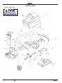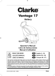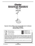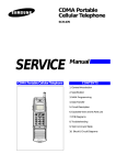
1
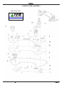
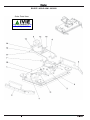
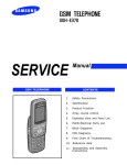
Order Parts Here:
www.ivie-ent.com/parts
Ph:(918)254-5161
Operator’s Manual
Libro de Instrucciones
Manuel d’utilisation
READ THIS BOOK
EN
English (1 - 24)
LEA ESTE MANUAL
ES
Español (.... - ....)
LISEZ CE MANUEL
FR
Français (.... - ....)
Form No. 9097861000 - 09/2008
ENGLISH
TABLE OF CONTENTS
INTRODUCTION ............................................................................................................................................. 2
MANUAL PURPOSE AND CONTENTS .......................................................................................................................................... 2
TARGET........................................................................................................................................................................................... 2
HOW TO KEEP THIS MANUAL....................................................................................................................................................... 2
IDENTIFICATION DATA................................................................................................................................................................... 2
OTHER REFERENCE MANUALS ................................................................................................................................................... 2
SPARE PARTS AND MAINTENANCE ............................................................................................................................................. 2
CHANGES AND IMPROVEMENTS ................................................................................................................................................ 2
OPERATION CAPABILITIES ........................................................................................................................................................... 2
CONVENTIONS .............................................................................................................................................................................. 2
UNPACKING/DELIVERY ................................................................................................................................ 3
SAFETY .......................................................................................................................................................... 3
SYMBOLS ....................................................................................................................................................................................... 3
GENERAL INSTRUCTIONS ............................................................................................................................................................ 3
SYMBOLS SHOWN ON THE MACHINE......................................................................................................................................... 5
MACHINE DESCRIPTION .............................................................................................................................. 6
MACHINE STRUCTURE ................................................................................................................................................................. 6
CONTROL PANEL ........................................................................................................................................................................... 7
VIEW UNDER TANK COVERS ....................................................................................................................................................... 8
VIEW UNDER TANK ASSEMBLY .................................................................................................................................................... 8
ACCESSORIES/OPTIONS ............................................................................................................................. 9
TECHNICAL DATA........................................................................................................................................................................... 9
WIRING DIAGRAM ........................................................................................................................................................................ 10
USE ............................................................................................................................................................... 11
BATTERY CHECK/SETTING ON A NEW MACHINE .....................................................................................................................11
BATTERY INSTALLATION AND BATTERY TYPE SETTING (WET OR GEL) .............................................................................. 12
BEFORE START-UP...................................................................................................................................................................... 13
MACHINE START AND STOP ....................................................................................................................................................... 14
MACHINE OPERATION (SCRUBBING/DRYING)......................................................................................................................... 15
AFTER USING THE MACHINE ..................................................................................................................................................... 16
PUSHING/TOWING THE MACHINE ............................................................................................................................................. 16
MACHINE LONG INACTIVITY ...................................................................................................................................................... 17
FIRST PERIOD OF USE ............................................................................................................................................................... 17
MAINTENANCE ............................................................................................................................................ 17
SCHEDULED MAINTENANCE TABLE ......................................................................................................................................... 17
MACHINE WORKING HOUR CHECK .......................................................................................................................................... 17
SQUEEGEE CLEANING ............................................................................................................................................................... 18
SQUEEGEE BLADE CHECK AND REPLACEMENT .................................................................................................................... 18
BRUSH CLEANING ....................................................................................................................................................................... 19
CLEANING OF TANK AND VACUUM GRID WITH FLOAT ........................................................................................................... 19
SIDE SKIRT CHECK AND REPLACEMENT ................................................................................................................................. 20
VACUUM SYSTEM MOTOR FILTER CLEANING ......................................................................................................................... 21
SOLUTION FILTER CLEANING .................................................................................................................................................... 21
BATTERY CHARGING .................................................................................................................................................................. 22
FUSE CHECK/REPLACEMENT .................................................................................................................................................... 23
EMERGENCY PUSH-BUTTON ..................................................................................................................................................... 23
SPEED REDUCTION AT BENDS .................................................................................................................................................. 23
DRIVER SEAT MICROSWITCH .................................................................................................................................................... 23
ELECTROMAGNETIC BRAKE ...................................................................................................................................................... 23
TROUBLESHOOTING .................................................................................................................................. 24
SCRAPPING ................................................................................................................................................. 24
Parts List ...................................................................................................................................................... 73
Operator’s Manual - CR 28 BOOST®
1
ENGLISH
INTRODUCTION
NOTE
The numbers in brackets refer to the components shown in Machine Description chapter.
MANUAL PURPOSE AND CONTENTS
The purpose of this Manual is to provide the operator with all necessary information to use the machine properly in a safe and
autonomous way. It contains information about technical data, safety, operation, storage, maintenance, spare parts and disposal.
Before performing any procedure on the machine, the operators and qualified technicians must read this Manual carefully. Contact
Clarke in case of doubts concerning the interpretation of the instructions and for any further information.
TARGET
This Manual is intended for operators and technicians qualified to perform the machine maintenance.
The operators must not perform procedures reserved for qualified technicians. Clarke will not be answerable for damages coming
from the non-observance of this prohibition.
HOW TO KEEP THIS MANUAL
The Operator's Manual must be kept near the machine, inside an adequate case, away from liquids and other substances that can
cause damage to it.
IDENTIFICATION DATA
The machine model and serial number are marked on the plate (30).
The machine production year is indicated by the first two figures of the machine serial number.
This information is useful when requiring machine spare parts. Use the following table to write down the machine identification data.
MACHINE model ...............................................................................
MACHINE serial number ...................................................................
OTHER REFERENCE MANUALS
–
Electronic battery charger Manual (to be considered as integral part of this Manual)
Moreover, the following Manuals are available:
–
Service Manual (that can be consulted at any Clarke Service Center)
–
Spare Parts List (supplied with the machine)
SPARE PARTS AND MAINTENANCE
All necessary operating, maintenance and repair procedures must be performed by qualified personnel or by Clarke Service
Centers. Only original spare parts and accessories must be used.
Call Clarke for service or to order spare parts and accessories, specifying the machine model and serial number.
CHANGES AND IMPROVEMENTS
Clarke constantly improves its products and reserves the right to make changes and improvements at its discretion without being
obliged to apply such benefits to the machines that were previously sold.
Any change and/or addition of accessory must be approved and performed by Clarke.
OPERATION CAPABILITIES
This scrubber-dryer is used to clean (scrubbing and drying) smooth and solid floors, in civil or industrial environment, under safe
operation conditions by a qualified operator.
The scrubber-dryer cannot be used for moquette and carpet cleaning.
CONVENTIONS
Forward, backward, front, rear, left or right are intended with reference to the operator’s position, that is to say on the driver’s seat
(25).
2
Operator’s Manual - CR 28 BOOST®
ENGLISH
UNPACKING/DELIVERY
To unpack the machine carefully follow the instructions on the packing.
Upon delivery carefully check that the machine and its packing have not been damaged during transportation. In case of visible
damages, keep the packing and have it checked by the carrier that delivered it. Call the carrier immediately to fill in a damage claim.
Check that the machine is equipped with the following features:
–
Technical documents:
• Scrubber-dryer Operator's Manual
• Electronic battery charger Manual (integral part of this manual)
• Scrubber-dryer Spare Parts List
–
No. 2 lamellar fuses
–
No. 5 spacers for 6 V battery housing
–
One 2 mm-wrench for socket screws
SAFETY
The following symbols indicate potentially dangerous situations. Always read this information carefully and take all necessary
precautions to safeguard people and property.
The operator's cooperation is essential in order to prevent injury. No accident prevention program is effective without the total
cooperation of the person responsible for the machine operation. Most of the accidents that may occur in a factory, while working
or moving around, are caused by failure to comply with the simplest rules for exercising prudence. A careful and prudent operator is
the best guarantee against accidents and is essential for successful completion of any prevention program.
SYMBOLS
DANGER!
It indicates a dangerous situation with risk of death for the operator.
WARNING!
It indicates a potential risk of injury for people or damage to objects.
CAUTION!
It indicates a caution or a remark related to important or useful functions. Pay careful attention to the
paragraphs marked by this symbol.
NOTE
It indicates a remark related to important or useful functions.
CONSULTATION
It indicates the necessity to refer to the Operator's Manual before performing any procedure.
GENERAL INSTRUCTIONS
Specific warnings and cautions to inform about potential damages to people and machine are shown below.
DANGER!
–
Before performing any maintenance, repair, cleaning or replacement procedure the battery connector must
be disconnected and the key must be removed from the ignition switch.
–
This machine must be used by properly trained operators only. Children or disabled people cannot use this
machine.
–
Keep the battery far from sparks, flames and incandescent material. During normal operation, explosive
gases are released.
–
Do not wear jewelry when working near electrical components.
–
Do not work under the lifted machine without supporting it with safety stands.
–
Do not operate the machine near toxic, dangerous, flammable and/or explosive powders, liquids or vapors.
This machine is not suitable for picking up hazardous materials.
–
Battery charging produces highly explosive hydrogen gas. Keep the tank assembly open during battery
charging and perform this procedure in well-ventilated areas and away from open flames.
Operator’s Manual - CR 28 BOOST®
3
ENGLISH
WARNING!
–
Carefully read all the instructions before performing any maintenance/repair procedure.
–
Before using the battery charger, ensure that frequency and voltage values, indicated on the machine serial
number plate, match the electrical mains voltage.
–
To reduce the risk of fire, electric shock, or injury, do not leave the machine unattended when it is plugged
in. Unplug the machine from the electrical mains when not in use and before servicing.
–
To avoid electric shock, do not expose to rain. Store the machine indoors.
–
Do not allow to be used as a toy. Close attention is necessary when used near children.
–
Use only as shown in this Manual. Use only Clarke's recommended accessories.
–
Do not use with damaged battery charger cable or plug. If the machine is not working as it should, has been
damaged, left outdoors or dropped into water, return it to the Service Center.
–
Do not pull or carry the machine by the battery charger cable and never use the battery charger cable as
a handle. Do not close a door on the battery charger cable, or pull the battery charger cable around sharp
edges or corners. Do not run the machine on the battery charger cable. Keep the battery charger cable
away from heated surfaces.
–
Take all necessary precautions to prevent hair, jewelry and loose clothes from being caught by the machine
moving parts.
–
Do not smoke while charging the batteries.
–
Do not wash the machine with direct or pressurized water jets, or with corrosive substances.
–
To avoid any unauthorized use of the machine, remove the ignition key.
–
Do not leave the machine unattended without being sure that it cannot move independently.
–
Do not use the machine on slopes with a gradient exceeding the specifications.
–
Use only pads supplied with the machine and those specified in the Operator's Manual. Using other
brushes or pads could reduce safety.
–
Before using the machine, close all doors and/or covers.
–
Do not use the machine in particularly dusty areas.
–
While using this machine, take care not to cause damage to other people, especially children.
–
Do not put any can containing fluids on the machine.
–
The machine storage temperature must be between +32°F and +104°F (0°C and +40°C).
–
The machine working temperature must be between +32°F and +104°F (0°C and +40°C).
–
The humidity must be between 30% and 95%.
–
Always protect the machine against the sun, rain and bad weather, both under operation and inactivity
condition. Store the machine indoors, in a dry place. This machine must be used in dry conditions, it must
not be used or kept outdoors in wet conditions.
–
Do not use the machine as a means of transport.
–
Do not allow the brush to operate while the machine is stationary to avoid damaging the floor.
–
In case of fire, use a powder fire extinguisher, not a water one.
–
Do not bump into shelves or scaffoldings, especially where there is a risk of falling objects.
–
Do not tamper with the machine safety guards and follow the routine maintenance instructions
scrupulously.
–
To move the machine by hand it is necessary to disengage the electromagnetic brake. After moving
the machine by hand, the electromagnetic brake must be engaged. Do not use the machine when the
electromagnetic brake is disengaged.
–
Do not remove or modify the plates affixed to the machine.
–
In case of machine malfunctions, ensure that these are not caused by a lack of maintenance. Otherwise,
request assistance from the authorized personnel or from an authorized Service Center.
–
If parts must be replaced, require ORIGINAL spare parts from an authorized Dealer or Retailer.
–
To ensure machine proper and safe operation, the scheduled maintenance shown in the relevant chapter of
this Manual must be performed by the authorized personnel or by an authorized Service Center.
–
Do not allow any object to enter into the openings. Do not use the machine if the openings are clogged.
Always keep the openings free from dust, hairs and any other foreign material which could reduce the air
flow.
–
This machine cannot be used on roads or public streets.
–
Pay attention during the machine transfers when temperature is below freezing point. The water in the
recovery tank or in the hoses could freeze and seriously damage the machine.
–
When lead (WET) batteries are installed on the machine, do not tilt the machine more than 30° from the
horizontal plane to prevent the highly corrosive acid from leaking out of the batteries. If the machine must
be tilted to perform any maintenance procedure, remove the batteries.
4
Operator’s Manual - CR 28 BOOST®
ENGLISH
SYMBOLS SHOWN ON THE MACHINE
WARNING!
Carefully read all instructions before performing any procedure on the machine.
WARNING!
Do not wash the machine with direct or pressurized water jets.
Operator’s Manual - CR 28 BOOST®
5
ENGLISH
MACHINE DESCRIPTION
MACHINE STRUCTURE
1.
2.
3.
4.
5.
6.
7.
8.
9.
10.
11.
12.
13.
14.
15.
16.
17.
18.
Steering wheel inclination control lever
Steering wheel
Drive pedal
BOOST® deck
BOOST® deck motor
Side skirts
Battery charger cable housing
Battery charger cable
Solution filter
Recovery water drain hose
Squeegee vacuum hose
Squeegee
Bumper wheels
Squeegee support wheels
Squeegee mounting handwheels
Squeegee balance adjusting handwheel
Front squeegee blade
Rear squeegee blade
19.
20.
21.
22.
23.
24.
25.
26.
27.
28.
29.
30.
Squeegee rear blade fastening hook
Solution tank
Recovery tank
Recovery tank cover
Flashing light (optional)
Solution drain hose
Seat
Battery charger
Electromagnetic brake
Front steering, driving and braking wheel
Electromagnetic brake unlocking screws
Serial number plate/technical data
23
22
2
1
21
30
20
10
7
3
8
13
13
15
25
11
16
9
4
14 12
19 15
14
18
6
13
17
26
28
27 29 5 4
6
13 24 13
S311377A
6
Operator’s Manual - CR 28 BOOST®
ENGLISH
CONTROL PANEL
31. Control panel
32. Emergency push-button
33. Horn
34. Scrub and vacuum activation button
35. Extra pressure button
36. Squeegee lifting/lowering and vacuum system on/off button
37. Battery charge indicator
37a. Charged battery warning light (green)
37b. Semi-discharged battery warning light (yellow)
37c. Discharged battery warning light (red)
38. Hour counter and solution level display:
• When the machine is started, it displays for a few
seconds the number of working hours which have been
performed.
• While using the machine, it displays the solution level
in the tank (measured in percentage terms, compared
with the full tank).
• When the level is below 20%, the display starts
blinking.
• The display could indicate “000 %” even if the tank is
not completely empty, allowing to complete the cleaning
procedures; in any case, please check the actual
solution flow to the brushes.
39. Forward/reverse gear switch
40. Solution flow adjustment
40a. Flow increase button
37
40b. Flow decrease button
40c. Flow LEDs:
• 0 LEDs on - The solution flow is closed.
• 1 LED on - 0.29 gal/min (1.1 liters/min).
• 2 LEDs on - 0.5 gal/min (1.9 liters/min).
• 3 LEDs on - 0.74 gal/min (2.8 liters/min).
41. Ignition key
37c 37b 37a
38
34
40
40a
40c
35
40b
36
33
31
32
41
39
S311212A
Operator’s Manual - CR 28 BOOST®
7
ENGLISH
VIEW UNDER TANK COVERS
51.
52.
53.
54.
55.
56.
57.
58.
Recovery tank cover
Recovery tank cover gasket
Recovery water vacuum duct
Vacuum screen with automatic shut-off float
Float
Screen fasteners
Solution inlet opening
Solution tank cover/driver's seat
59. Cover support rod
60. Recovery tank
61. Solution tank
S311219A
VIEW UNDER TANK ASSEMBLY
71.
72.
73.
74.
Tank assembly
Batteries
Battery case
Battery connector
75. Battery caps
76. Battery connection diagrams
77. Vacuum system motor sound-deadening filter
S311220A
8
Operator’s Manual - CR 28 BOOST®
ENGLISH
ACCESSORIES/OPTIONS
In addition to the standard components, the machine can be equipped with the following accessories/options, according to the
machine specific use:
–
AGM batteries
–
Brushes of different materials
–
Flashing light
–
Hose filling
–
Silencer reverse alarm
For further information concerning the above-mentioned optional accessories, contact an authorized Retailer.
TECHNICAL DATA
Description
CR 28 BOOST®
Cleaning width
28 in (711 mm)
Squeegee width
34 in (864 mm)
Solution tank capacity
19.8 gal (75 liters)
Min/max solution flow
0/0.74 gal/min (0/2.8 liters/min)
Recovery tank capacity
19.8 gal (75 liters)
Rear wheel
11.8 in (300 mm)
Wheel specific pressure on the floor
Front 116 psi (0.8 N/mm2 ) - Rear 145 psi (1.0 N/mm2)
Front steering, driving and braking wheel diameter
9.8 in (250 mm)
Vacuum system motor power
0.67 hp (500 W)
Drive system motor power
0.80 hp (600 W)
Drive speed (variable)
Gradeability
From 0 to 3.7 mph (from 0 to 6 km/h)
16% (9°)
Sound pressure level at workstation (ISO 11201, ISO 4871) (LpA)
Machine sound pressure level (ISO 3744, ISO 4871) (LwA)
60.8 dB(A) ± 3dB(A)
82.4 dB(A)
Vibration level at the operator’s arms (*)
9 - 29.5 in/s2 (0.23 – 0.75 m/s2)
Vibration level at the operator’s body (*)
< 47.2 in/s2 (< 1.2 m/s2)
24 V battery box: 23.6 x 15.3 x 11.8 in (600 x 390 x 300 mm)
Battery compartment size
Four 6 V batteries:
Wet and maintenance free available
Vacuum system capacity
70.9 in (1,800 mmH2O)
Machine height
49.2 in (1,250 mm)
Machine maximum length
57.1 in (1,450 mm)
Machine width without squeegee
26 in (658 mm)
Brush/pad width
28 in (711 mm)
Weight without batteries and with empty tanks
308 lbs (140 kg)
Maximum weight with batteries and full tanks
848.7/1036 lbs (385/470 Kg)
Brush/pad motor power
0.75 hp (560 W)
Brush/pad-holder speed
2200 rpm
Brush/pad-holder pressure with extra-pressure function turned off
66 lbs (30 Kg)
Brush/pad-holder pressure with extra-pressure function turned on
110 lbs (50 Kg)
(*)
Under normal working conditions, on a level asphalt surface.
Operator’s Manual - CR 28 BOOST®
9
ENGLISH
WIRING DIAGRAM
Key
BAT
BE
BRK
BZ1
C1
C2
C3
CH
CS
CSC
EB1
EB2
EB3
EB3/2
EV1
F1
F2
F3
F4
K1
LD1
M1
M2
M3
M4
M5
24 V batteries
Flashing light
Electromagnetic brake
Reverse gear warning buzzer/horn
Battery connector
Battery charger auxiliary connector
Battery charger external vent auxiliary connector
Battery charger
BOOST® deck connector
Deck sub-connector
Function electronic board
Drive system electronic board
Electronic board (under control panel)
Electronic board (under control panel) (optional)
Solenoid valve
Function electronic board fuse
Drive system electronic board fuse
Low power circuit fuse
Pump fuse (optional)
Ignition switch
Drive system electronic board diagnostic LED
Left brush motor
Right brush motor (if equipped)
Vacuum system motor
BOOST® deck actuator
Drive system motor
M6
M7
M8
M9
PR1
RV1
RV2
SW0
SW1
SW2
SW3
SW4
SW5
SW6
Squeegee actuator
Washing water pump (optional)
Detergent pump (optional)
Cooling fan
Washing water level sensor
Working speed potentiometer (if equipped)
Speed potentiometer (pedal)
Emergency push-button
Actuator position 0 micro-switch
Actuator position 1 micro-switch
Actuator position 2 micro-switch
Steering sensor
Driver's seat microswitch
Reverse gear switch
Color code
BK
BU
BN
GN
GY
OG
PK
RD
VT
WH
YE
Black
Blue
Brown
Green
Gray
Orange
Pink
Red
Violet
White
Yellow
S311379A
10
Operator’s Manual - CR 28 BOOST®
ENGLISH
USE
WARNING!
On some points of the machine there are some adhesive plates indicating:
–
DANGER
–
WARNING
–
CAUTION
–
CONSULTATION
While reading this Manual, the operator must pay particular attention to the symbols shown on the identification plates.
Do not cover identification plates for any reason and immediately replace them if damaged.
BATTERY CHECK/SETTING ON A NEW MACHINE
WARNING!
The electric components of this machine can be seriously damaged if batteries are either installed or connected
improperly. The batteries must be installed by qualified personnel only. Set the function electronic board and the
battery charger according to the type of batteries installed (WET or GEL).
Check the batteries for damage before installation.
Disconnect the battery connector and the battery charger plug.
Handle the batteries with great care.
Install the battery terminal protection caps supplied with the machine.
The machine requires one of the followings:
–
4 6 V batteries, 250 Ah (WET ACID)
–
4 6 V batteries, 255 Ah (MAINTENANCE FREE AGM)
The machine can be supplied in one of the following modes:
Batteries (WET or GEL) already installed and charged
1.
2.
3.
4.
5.
6.
Open the covers (51 and 58) and check that the tanks (60 and 61) are empty, otherwise drain them through the drain hose (10)
and the tap (24).
Close the covers (51 and 58).
Carefully lift the tank assembly (71).
Check that the batteries are connected to the machine with the connector (74).
Carefully lower the tank assembly (71).
Insert the ignition key (41) and turn it to “I”. If the green warning light (37a) turns on, the batteries are charged. If the yellow
(37b) or red warning light (37c) turns on, the batteries must be charged (see the procedure in Maintenance chapter).
Operator’s Manual - CR 28 BOOST®
11
ENGLISH
BATTERY INSTALLATION AND BATTERY TYPE SETTING (WET OR GEL)
According to the type of batteries (WET or GEL), set the machine and electronic board of the battery charger as follows:
Machine setting
1.
2.
3.
4.
5.
6.
Turn the ignition key (41) to “I” and in the very first seconds of machine operation pay attention to the following:
• If the green warning light (37a) is flashing, the machine is set to GEL (compatible with AGM).
• If the red warning light (37c) is flashing, the machine is set to WET.
To change the settings, proceed as follows.
Turn off the machine and turn the ignition key (41) to “0”.
Press and hold the switch (36), then turn the ignition key (41) to “I”.
Release the switch (36) at least 5 seconds after turning the machine on.
Press again the switch (36) for a few seconds and check that the warning light of the required setting is flashing.
Battery charger setting
7.
8.
9.
Remove the screws (A, Fig. 1) and the panel (B).
Turn the selector (C) to WET or GEL according to the type of batteries installed.
Install the panel (B), then tighten the screws (A).
Figure 1
S311218A
Battery installation
10. Open the covers (51 and 58) and check that the tanks (60 and 61) are empty, otherwise drain them through the drain hose (10)
and the tap (24).
11. Close the covers (51 and 58).
12. Carefully lift the tank assembly (71).
13. Install the batteries and connect them according to the diagram (76).
Battery charging
14. Charge the batteries (see the procedure in Maintenance chapter).
12
Operator’s Manual - CR 28 BOOST®
ENGLISH
BEFORE START-UP
WARNING!
At every machine start-up, check that, between the deck (4 or 5) and the machine or between the squeegee
(12) and the machine, there is no foreign material which may prevent the deck and the squeegee from lifting.
This check is necessary because, if the machine has been turned off without lifting the BOOST® deck and the
squeegee, when turned on again, the deck and the squeegee lift automatically.
Brush installation/removal
1.
2.
3.
4.
5.
6.
The machine can be equipped with different brushes (88) according to the type of floor to be cleaned.
For the installation/removal, proceed as follows.
Insert the ignition key (41) and turn it to “I”.
WARNING!
Before pressing the switch (34), always check that, between the deck (4) and the machine, there is no foreign
material which may prevent the deck from lifting.
Lift the deck by pressing the switch (34).
Turn the ignition key (41) to “0” and remove it.
Install the brush (88) so that it engages the BOOST® deck.
To remove the brush, perform steps 2 to 5 in the reverse order.
Brushes and Pads available
Pads
Size
Description
Part No.
14 x 28
Red (5 Pack)
997001
14 x 28
Black (5 Pack)
997000
14 x 28
White (5 Pack)
997002
14 x 28
Blue (5 Pack)
997006
14 x 28
Maroon (10 Pack)
997018
Brushes
Size
Description
Part No.
14 x 28
Poly Brush
30752A
14 x 28
Nylon Brush
30751A
14 x 28
Grit Brush
30753A
Brush application guide
Models
POLYPROPYLENE
NYLON
CLEAN GRIT
General cleaning:
Concrete
Terrazzo floor
Ceramic tiles/quarrystones
Marble
Vinyl tiles
Rubber tiles
Operator’s Manual - CR 28 BOOST®
13
ENGLISH
Squeegee installation
15. Install the squeegee (12) and fasten it with the handwheels (15), then connect the suction hose (11) to the squeegee.
16. With the handwheel (16), adjust the squeegee so that its rear blade (18) touches the floor along all its length and that the front
blade (17) is slightly detached from the floor.
Solution tank filling
17. Open the cover (58).
18. Fill the solution tank (61) with a solution suitable for the work to be performed.
Do not fill the solution tank completely, leave few inches from the edge.
Always follow the dilution instructions on the label of the chemical product used to prepare the solution.
The solution temperature must not exceed +104°F (+40°C).
WARNING!
Use only low-foam and non-flammable detergents, intended for automatic scrubber applications.
Operator's position adjustment
21. Using the lever (1), adjust the inclination of the steering wheel (2) to reach a comfortable position.
MACHINE START AND STOP
Starting the machine
1.
2.
3.
4.
5.
6.
7.
Prepare the machine as shown in the previous paragraph.
Turn the ignition key (41) to “I”, without pressing the drive pedal (3). Check if the green warning light (37a) turns on.
If the yellow (37b) or red warning light (37c) turns on, turn the ignition key back to “0” and charge the batteries (see the
procedure in Maintenance chapter).
Drive the machine to the working area, by keeping the hands on the steering wheel and by pressing the pedal (3).
The drive speed can be adjusted from zero to maximum speed according to the pressure on the pedal (3).
The forward/reverse gear can be selected with the switch (39) on the right side of the dashboard.
NOTE
The driver's seat (25) is equipped with a safety sensor, which allows the machine to be moved with the pedal (3) only
when the operator is on the driver's seat.
NOTE
The machine is equipped with an anti-tilting safety system that reduces the speed when turning, irrespectively of the
pressure on the pedal.
The reduction of speed when turning is not a malfunction but a characteristic that improves the machine stability in every
condition.
Lower the BOOST® deck and the squeegee by pressing the switch (34).
Press the solution flow adjusting switches (40) according to the type of cleaning to be performed.
Start scrubbing, by turning the steering wheel (2) and by moving the machine forward by pressing the pedal (3).
Stopping the machine
8.
9.
Release the pedal (3).
It is not necessary to lock the machine during stopping or parking, because the electromagnetic brake (27) activates
automatically when the drive pedal is not pressed.
10. Lift the BOOST® deck and the squeegee by pressing the switch (34).
14
Operator’s Manual - CR 28 BOOST®
ENGLISH
MACHINE OPERATION (SCRUBBING/DRYING)
1.
2.
Start the machine as shown in the previous paragraph.
If necessary, adjust the solution flow sent to the brushes by pressing the switches (40).
NOTE
For correct scrubbing/drying of floors at the sides of the walls, Clarke suggests to go near the walls with the right side of
the machine as shown in figure 2.
A
B
Figure 2
P100160
Squeegee adjustment
3.
If necessary, stop the machine and adjust the squeegee with the handwheel (16) so that the rear blade touches the floor along
all its length.
WARNING!
To avoid any damage to the floor surface, turn off the BOOST® deck when the machine stops in one place,
especially when the extra pressure function is on.
Working with the BOOST® deck extra pressure function turned on
4.
5.
If the dirt on the floor proves to be particularly difficult to clean, it is possible to work with an extra pressure of the BOOST®
deck on the floor by pressing the switch (35).
To return to normal pressure, press the switch (35) again.
The switch (35) is enabled only when the deck (4) is lowered and the switch warning light (34) is on.
CAUTION!
In case of brush motor overload due to BOOST® deck excessive pressure or too aggressive floors/brushes, a
safety system stops the BOOST® deck after about one minute of continuous overload.
The overload is shown by the three warning lights (37a, 37b, 37c) flashing simultaneously.
If the overload takes place when cleaning with the extra pressure function activated, the system automatically reduces the pressure on the brush by deactivating the extra pressure function. If the overload persists, the BOOST®
deck stops.
To start again after the BOOST® deck stop due to overload, stop the machine by turning the ignition key (41) to
“0”. Turn on the machine by turning the ignition key (80) to “I”.
Operator’s Manual - CR 28 BOOST®
15
ENGLISH
Battery discharge during operation
6.
Until the green warning light (37a) stays on, the batteries allow the machine to work normally.
When the green warning light (37a) turns off and first the yellow warning light (37b) and then the red warning light (37c) turn
on, the batteries must be charged.
• When the yellow warning light (37b) turns on, the machine residual autonomy will last for a few minutes (depending on
battery type).
• When the red warning light (37c) turns on the machine autonomy is over: after a few seconds the BOOST® deck
automatically stops and lifts. Only the machine vacuum and drive systems still operate, just to dry the wet floor and move
the machine to the charging area.
CAUTION!
Do not use the machine with discharged batteries, to avoid damaging the batteries and reducing the battery life.
NOTE
In case the machine drive system cannot be used to move the machine, see Pushing/Towing The Machine paragraph.
TANK EMPTYING
An automatic float shut-off system (54) stops the vacuum system when the recovery tank (60) is full.
The vacuum system deactivation is signaled by a sudden increase in the vacuum system motor noise frequency, also the floor has
not dried.
WARNING!
If the vacuum system turns off accidentally (for example, when the float is activated because of a sudden machine
movement), to resume the operation: turn off the vacuum system by pressing the switch (36), then open the cover
(22) and check that the float inside the screen (55) has gone down to the water level. Then close the cover (22) and
turn on the vacuum system by pressing the switch (36).
When the recovery tank (60) is full, empty it as shown below.
Recovery tank emptying
1.
2.
3.
4.
Stop the machine by releasing the pedal (3).
Lift the BOOST® deck and the squeegee by pressing the switch (34).
Drive the machine to the appointed disposal area.
Empty the recovery tank with the hose (10). Then, rinse the tank with clean water.
Solution Tank Emptying
5.
6.
Perform steps 1 to 3.
Empty the solution tank by means of the tap (24). Then, rinse the tank with clean water.
AFTER USING THE MACHINE
After working, before leaving the machine:
1. Remove the brush as shown in the relevant paragraph.
2. Empty the tanks (60 and 61) as shown in the previous paragraph.
3. Perform the daily maintenance procedures (see the Maintenance chapter).
4. Store the machine in a clean and dry place, with the brush and the squeegee lifted or removed.
PUSHING/TOWING THE MACHINE
To push/tow the machine easily when the drive system cannot be used, disengage the electromagnetic brake (27) by fully tightening
the screws (29) (turn them clockwise) with the supplied wrench.
When pushing/towing procedure is over, loosen the screws (29) by 3 turns approximately, to engage the electromagnetic brake (27).
WARNING!
If the screws (29) are not loosened as shown, the electromagnetic brake is deactivated.
WARNING!
Do not turn on the machine if the electromagnetic brake unlocking screws (29) are tightened (electromagnetic
brake deactivated).
For safety purposes, it is advisable to tighten the screws (29) only for the time necessary to move the machine
by hand.
16
Operator’s Manual - CR 28 BOOST®
ENGLISH
MACHINE LONG INACTIVITY
1.
2.
3.
If the machine is not going to be used for more than 30 days, proceed as follows:
Perform the procedures shown in After Using the Machine paragraph.
Before disconnecting the battery red connector (74) perform the following procedures:
• Open the covers (51 and 58) and check that the tanks (60 and 61) are empty, otherwise drain them through the drain hose
(10) and the tap (24).
• Close the covers (51 and 58).
• Carefully lift the tank assembly (71).
FIRST PERIOD OF USE
After the first 8 hours, check the machine fastening and connecting parts for proper tightening. Check the visible parts for integrity
and leakage.
MAINTENANCE
The lifespan of the machine and its maximum operating safety are ensured by correct and regular maintenance.
The following chart provides the scheduled maintenance. The intervals shown may vary according to particular working conditions,
which are to be defined by the person in charge of the maintenance.
WARNING!
The procedures must be performed with the machine off and the batteries disconnected.
Moreover, carefully read all the instructions in the Safety paragraph.
All scheduled or extraordinary maintenance procedures must be performed by qualified personnel, or by an authorized Service
Center.
This Manual describes only the easiest and most common maintenance procedures.
NOTE
For other maintenance procedures contained in the Scheduled Maintenance Table or for extraordinary maintenance
procedures see the specific Service Manual that can be consulted at any Service Center.
SCHEDULED MAINTENANCE TABLE
Daily, after using
the machine
Procedure
Weekly
Every six
months
Yearly
Squeegee cleaning
Brush cleaning
Cleaning of Tank and Vacuum screen and Float
Battery charging
Squeegee blade check and replacement
Side skirt check
Solution filter cleaning
Battery (WET) fluid level check
Screw and nut tightening check
(1)
Squeegee cable sliding shoe lubrication
(2)
Electromagnetic brake efficiency check
(2)
BOOST® deck motor carbon brush check or replacement
(2)
Vacuum system motor carbon brush check or replacement
(2)
Drive system motor carbon brush check or replacement
(2)
(1) And after the first 8 working hours.
(2) This maintenance procedure must be performed by Clarke authorized Service Center.
MACHINE WORKING HOUR CHECK
1.
2.
Insert the ignition key (41) and turn it to “I”.
In the first 5 seconds of machine operation, the display (38) shows the total number of working hours (scrubbing/drying)
performed by the machine.
Turn the ignition key (41) to “0”.
Operator’s Manual - CR 28 BOOST®
17
ENGLISH
SQUEEGEE CLEANING
NOTE
The squeegee must be clean and its blades must be in good conditions in order to get a good drying.
CAUTION!
It is advisable to use protective gloves when cleaning the squeegee because there may be sharp debris.
1.
2.
3.
4.
5.
6.
7.
8.
Drive the machine on a level floor.
Insert the ignition key (41) and turn it to “I”.
Lower the squeegee (12) by pressing the switch (36).
Turn the ignition key (41) to “0”.
Disconnect the vacuum hose (11) from the squeegee.
Loosen the handwheels (15) and remove the squeegee (12).
Wash and clean the squeegee. In particular, clean the compartments (A, Fig. 3) and the hole (B) from dirt and debris. Check
the front blade (C) and the rear blade (D) for integrity, cuts and tears; otherwise replace them.
Reassemble in the reverse order of disassembly.
SQUEEGEE BLADE CHECK AND REPLACEMENT
1.
2.
3.
4.
5.
6.
Clean the squeegee as shown in the relevant paragraph.
Check that the edges (E and N, Fig. 3) of the front (17) and rear blades (18) lay down on the same level, along all their length;
otherwise adjust their height according to the following procedure:
• Disengage the fastener (F) and loosen the wing nuts (G) to adjust the rear blade (D); then tighten the wing nuts and
engage the fastener.
• Loosen the wing nuts (H) to adjust the front blade (C); then tighten the nuts.
Check the front blade (C) and rear blade (D) for integrity, cuts and tears; otherwise replace them according to the following
procedure. Check that the front corner (I) of the rear blade is not worn; otherwise, overturn the blade to replace the worn
corner with an integral one. If the other corners are worn too, replace the blade as shown below:
• Disengage the fastener (F), remove the wing nut (G) and the retaining strip (L), then replace (or overturn) the rear blade
(D). Install the blade in the reverse order of removal.
• Remove the wing nuts (H) and the retaining strip (M), then replace the front blade (C). Install the blade in the reverse order
of removal.
After the blade replacement (or overturning), adjust the height as shown in the previous step.
Install the squeegee (12) and screw down the handwheels (15).
Connect the vacuum hose (11) to the squeegee (12).
If necessary, adjust the squeegee balance adjusting handwheel (16).
Figure 3
S311216A
18
Operator’s Manual - CR 28 BOOST®
ENGLISH
BRUSH CLEANING
CAUTION!
It is advisable to use protective gloves when cleaning the brush because there may be cutting debris.
1.
2.
3.
Remove the brush as shown in Use chapter.
Clean and wash the brush with water and detergent.
Check the brush for integrity and replace it if necessary.
CLEANING OF TANK AND VACUUM SCREEN WITH FLOAT
1.
2.
3.
4.
5.
6.
Drive the machine to the appointed disposal area.
Turn the ignition key (41) to “0”.
Open the covers (51 and 58).
Clean and wash with clean water the covers (51 and 58), the tanks (60 and 61) and the vacuum screen (54) with automatic
shut-off float.
Drain the water in the tanks through the hose (10) and the tap (24).
If necessary, disengage the fasteners (A, Fig. 4) and open the screen (B); recover the float (C), clean all the components and
then reinstall them.
Check the tank cover gasket (D) for integrity.
NOTE
The gasket (D) creates vacuum in the tank that is necessary for vacuuming the recovery water.
7.
8.
If necessary replace the gasket (D) after removing it from its housing (E). When assembling the new gasket, install the joint (F)
in the rear central area, as shown in the figure.
Check the bearing surface (D) of gasket (G) for integrity and sealing capabilities.
Close the covers (51 and 58).
Figure 4
S311217A
Operator’s Manual - CR 28 BOOST®
19
ENGLISH
SIDE SKIRT CHECK AND REPLACEMENT
Check
1.
2.
3.
4.
5.
Drive the machine on a level floor.
Turn the ignition key (41) to “0”.
On both sides of the machine, lift and remove the side skirt assembly (A) from the holders (B).
Wash and clean the side skirts.
Check that the side skirt lower edge (C):
• Lays down on the same level, along all its length
• Is integral and free from cuts and lacerations
• Has the inner corner that is not worn
Otherwise replace the skirt as shown below.
Replacement
6.
7.
Remove the screws (D), then remove the retaining strip (E).
Remove the skirt blade (F) and replace it.
Assembly
8.
Assemble the blades (F) and the skirt assembly (A) in the reverse order of removal.
Adjustment
9. Lower Boost head and turn off the ignition key.
10. Release the clamp (G) and press down on the assembly so the inner blade contacts the floor.
11. While holding the inner blade against the floor, return the clamp (G) to the locked position.
Figure 5
S311214A
20
Operator’s Manual - CR 28 BOOST®
ENGLISH
VACUUM SYSTEM MOTOR FILTER CLEANING
1.
2.
3.
4.
5.
6.
7.
8.
9.
Drive the machine to the appointed disposal area and drain the water from the recovery tank (60) with the hose (10).
Drain the solution from the tank (61) with the tap (24).
Drive the machine on a level ground.
Turn the ignition key (42) to “0”.
Disconnect the vacuum hose (11) from the squeegee (12).
Fully lift the tank assembly (71) with care.
Remove the vacuum system motor filter (77) and clean it with water and compressed air.
Install the filter.
Fully lower the tank assembly (71) with care.
SOLUTION FILTER CLEANING
1.
2.
3.
4.
Drive the machine on a level floor.
Turn the ignition key (41) to “0”.
Close the solution valve (E, Fig. 6) under the machine, behind the right rear wheel. The valve (E) is closed when it is on the
position (F) and it is open when it is on the position (G).
Remove the transparent cover (A), then remove the filter strainer (B) under the machine in front of the right rear wheel. Clean
and reassemble the components on the support (C).
NOTE
The filter strainer (B) must be correctly positioned on the housing (D) of the support (C).
5.
Open the valve (E).
Figure 6
S311214A
Operator’s Manual - CR 28 BOOST®
21
ENGLISH
BATTERY CHARGING
NOTE
Charge the batteries when the yellow (37b) or red warning light (37c) turns on, or when finishing cleaning.
CAUTION!
Keeping the batteries charged make them last longer.
CAUTION!
When the batteries are discharged, charge them as soon as possible, as that condition makes them last shorter.
Check for battery charge at least once a week.
WARNING!
Battery charging produces highly explosive hydrogen gas. Charge the batteries in well-ventilated areas and
away from naked flames.
Do not smoke while charging the batteries.
While charging the battery, always keep the tank assembly open.
WARNING!
Be extremely careful when charging the batteries as there may be battery fluid leakages. The battery fluid is
corrosive. If it comes in contact with skin or eyes, rinse thoroughly with water and call a physician.
Battery charging with battery charger installed on the machine
1.
2.
3.
Drive the machine on a level floor.
For WET batteries only:
• Open the covers (51 and 58) and check that the tanks (60 and 61) are empty, otherwise drain them through the drain hose
(10) and the tap (24).
• Close the covers (51 and 58).
• Carefully lift the tank assembly (71).
• Check the level of electrolyte inside the batteries (72). If necessary, remove the caps (75) and top off.
• When the correct level is reached, close the caps (75) and clean, if necessary, the upper surface of the batteries.
Connect the battery charger cable (8) to the electrical mains (the electrical mains voltage and frequency must be compatible
with the battery charger values shown on the machine serial number plate).
NOTE
When the battery charger is connected to the electrical mains, all machine functions are automatically cut off.
4.
5.
6.
7.
If the red warning light (F, Fig. 7) on the battery charger control panel stays on, the battery charger is charging the batteries.
When the green warning light (H) turns on, the battery charging is completed.
When the battery charging is completed, disconnect the battery charger cable (8) from the electrical mains and wind it round
its housing (7).
For WET batteries only:
• Carefully lower the tank assembly (71).
• Fill the tanks (60 and 61).
The machine is ready to be used.
NOTE
For further information about the battery charger operation (I), see the relevant Manual.
22
Operator’s Manual - CR 28 BOOST®
ENGLISH
FUSE CHECK/REPLACEMENT
1.
2.
3.
4.
Turn the ignition key (41) to “0”.
Remove the nuts (E, Fig. 7), then remove the cover (A).
Check and, if necessary, replace the following fuses:
B. Low power circuit protection fuse (F3): (5 A)
C. Drive system electronic board protection fuse (F2): (60 A)
D. Function electronic board protection fuse (F1): (100 A)
Install the cover and tighten the nuts.
Figure 7
S311214A
SAFETY FUNCTIONS
The machine is equipped with the following safety functions.
EMERGENCY PUSH-BUTTON
It is located in a position (32) that is easily accessible for the operator. Press it in case of immediate necessity to stop all machine
functions.
To reset it, turn it clockwise.
SPEED REDUCTION AT BENDS
It reduces the machine speed in case of bends exceeding a specified angle.
DRIVER SEAT MICROSWITCH
It is inside the driver's seat and it prevents the drive system operation when the operator is not on the driver's seat.
ELECTROMAGNETIC BRAKE
Built-in the front wheel, it keeps the machine stopped when: the machine is off, when the emergency stop button is pushed and
when the drive pedal is not pressed.
Operator’s Manual - CR 28 BOOST®
23
ENGLISH
TROUBLESHOOTING
TROUBLE
POSSIBLE CAUSE
ACTION
The battery connector (74) is disconnected.
Connect.
The battery (72) are totally discharged.
Charge.
The machine does not move.
The machine has been turned on with the
ignition key (41) while pressing the pedal (3).
Turn the machine off and then turn it on
without pressing the drive pedal.
When turning on the machine, the switch warning
light (34) flashes and the BOOST® deck does not
operate.
The machine has been turned off without
lifting the BOOST® deck.
Wait for the BOOST® deck to lift fully before
pressing the switch (34) again.
The warning lights (37) flash simultaneously.
The BOOST® deck motor is overloaded.
Use less aggressive brushes suitable for the
floor to be cleaned or avoid working with extra
pressure function activated.
The BOOST® deck does not operate; the red
warning light (37c) flashes.
The batteries are discharged.
Charge.
The recovery tank (60) is full.
Empty.
The vacuum screen (55) is clogged or the
float is closing.
Clean the vacuum screen.
The hose (11) is disconnected from the
squeegee.
Connect.
The squeegee (12) is dirty or the squeegee
blades are worn or damaged.
Clean the squeegee or overturn/replace the
blades.
The tank cover is not properly closed, or the
gasket (52) is damaged.
Close the cover properly or clean/replace the
gasket.
The solution tank is empty.
Fill.
The solution filter (9) is dirty.
Clean.
The tank (61) is dirty, the output hole is
clogged.
Clean.
There is debris under the squeegee blades
(17 - 18).
Clean.
The squeegee blades (17 - 18) are worn,
chipped or torn.
Overturn or replace.
The motors do not work; no warning light turns on.
Dirty water vacuuming is insufficient.
The solution flow is insufficient.
The squeegee leaves marks on the floor.
The squeegee has not been balanced with the
Adjust.
handwheel (16).
NOTE
The machine cannot operate without the battery charger on board.
In case of battery charger malfunction, contact an authorized Service Center.
For further information, contact Clarke Service Centers.
SCRAPPING
Have the machine scrapped by a qualified scrapper.
Before scrapping the machine, remove and separate the following materials, which must be disposed of properly according to the
Law in force:
–
Batteries
–
Brush
–
Plastic hoses and components
–
Electrical and electronic components (*)
(*)
Refer to the nearest Clarke Center especially when scrapping electrical and electronic components.
24
Operator’s Manual - CR 28 BOOST®
Parts List
Form No. 9097861000 - 09/2008
[ ] = Not shown
* = optional
# = Modified item No. or New item No.
Order Parts Here:
GENERAL VIEW
www.ivie-ent.com/parts
Ph:(918)254-5161
74
Parts List - CR 28 BOOST®
GENERAL VIEW - 09/2008
Ref.
1
2
3#
4
5
6#
7#
8#
9#
10#
11#
12#
13
14#
15#
16
17
[18]
[19]
Part No.
145 1129 000
145 1894 000
9097390000
9097391000
146 0765 000
909 6068 000
909 6158 000
40136A
56315772
Description
WASHER 16X6
SCREW M6X30
SQUEEGEE SYSTEMS (SEE PAGE 96)
HATCH RIGHT
HATCH LEFT
BRUSH SYSTEMS (SEE PAGE 98)
FRONT WHEEL ASSEMBLY (SEE PAGE 82)
SOLUTION SYSTEM (SEE PAGE 94)
SQUEEGE SUPPORT SYSTEM (SEE PAGE 96)
FOOTBOARD ASSEMBLY (SEE PAGE 92)
BRUSH DECK LIFTING SYSTEM (SEE PAGE 106)
STEERING SYSTEM (SEE PAGE 86)
SCREW 6X10
CHASSIS ASSEMBLY (SEE PAGE 80)
TANKS ASSEMBLY (SEE PAGE 76)
BATTERY CONTAINER
BOX FOR BATTERY CHARGER CABLE
BATTERY 6V 250 AH WET
BATTERY 6V 255 AH AGM
Qty
6
6
1
1
1
1
1
1
1
1
1
1
2
1
1
1
1
4
4
Order Parts Here:
www.ivie-ent.com/parts
Ph:(918)254-5161
NOTE: # indicates a change has been made since the last pubblication of this manual
Parts List - CR 28 BOOST®
75
TANKS ASSEMBLY
Order Parts Here:
www.ivie-ent.com/parts
Ph:(918)254-5161
76
Parts List - CR 28 BOOST®
TANKS ASSEMBLY - 09/2008
Ref.
1
2
3#
4#
Part No.
909 6245 000
909 6401 000
Description
FRESH WATER TANK
HARDWARE WATER TANK KIT
SEAT ASSEMBLY ((SEE PAGE 104)
RECOVERY TANK (SEE PAGE 78)
Qty
1
1
1
1
Order Parts Here:
www.ivie-ent.com/parts
Ph:(918)254-5161
NOTE: # indicates a change has been made since the last pubblication of this manual
Parts List - CR 28 BOOST®
77
RECOVERY TANK
Order Parts Here:
www.ivie-ent.com/parts
Ph:(918)254-5161
78
Parts List - CR 28 BOOST®
RECOVERY TANK - 09/2008
Ref.
1
2
3
4
5
6
7
8
9
10
11
12
13
14
15
16
17#
18
19
20
21
22
[23]
Part No.
9097340000
909 6489 000
9097466000
909 6051 000
9097399000
909 6490 000
909 6442 000
909 6491 000
9097393000
145 0543 000
9097394000
909 6247 000
909 6268 000
L08812968
909 6199 000
L08812373
L08812259
909 6876 000
909 6877 000
909 6380 000
909 6810 000
909 5371 000
909 6812 000
Description
RECOVERY TANK BLUE
GASKET VACUUM MOTOR
MOTOR VACUUM 3ST 500W CPL
COVER VACUUM MOTOR
FILTER
GASKET VACUUM MOTOR
PIPE ACOUSTIC INSULATION
PANEL ACOUSTIC INSULATION
HOSE DRAIN BLACK
CLAMP 24/32-52
HOSE VACUUM BLACK
COVER TANK BLUE
GASKET
GASKET
HOLDER FLOAT CAGE
BALL FLOATING
CAGE FLOAT CPL
HARDWARE RECOVERY TANK KIT
HARDWARE MOTOR FIXING KIT
CLAMP KIT
COVER TANK LOCKING KIT
CARBON BRUSH
INSTALLATION INSTRUCTION COVER TANK LOCKING KIT
Qty
1
1
1
1
1
1
1
1
1
1
1
1
1
1
1
1
2
1
1
1
1
2
1
Order Parts Here:
www.ivie-ent.com/parts
Ph:(918)254-5161
NOTE: # indicates a change has been made since the last pubblication of this manual
Parts List - CR 28 BOOST®
79
CHASSIS SYSTEM
Order Parts Here:
www.ivie-ent.com/parts
Ph:(918)254-5161
80
Parts List - CR 28 BOOST®
CHASSIS SYSTEM
Ref.
1
2
3
4
5
6
7
8
9
10
11
12
13
14
15
16
17
18
19
20
21
22
23
24
[25]
Part No.
9097206000
909 6065 000
L08812248
33003824
33004368
909 6240 000
145 2612 000
146 0987 000
33004010
909 6066 000
9097389000
909 6069 000
909 6070 000
909 6715 000
909 6151 000
909 6364 000
909 6365 000
909 6366 000
909 6367 000
909 6718 000
909 6368 000
33005608
L08604251
9097207000
909 6719 000
Description
SUPPORT ROLLER BUMPER
CHASSIS
BUMPER ROLLER
SCREW M10X150 UNI5737
SCREW M8X35
PLATE
PULLEY
CLAMP
SCREW HEX M10X30 UNI5739
ACTUATOR PROTECTION
REAR WHEEL Ø 300X70
BAR PROTECTION CABLE
DRAIN HOSE BRACKET
JACK MOTOR 24V
TANK CABLE
REAR WHEELS FITTING KIT
KIT TANK CABLE
BAR PROTECTION FITTING KIT
ACTUATOR’S PIN FITTING KIT
CABLE SQUEEGEE KIT
CHASSIS HARDWARE KIT
NUT SELF L. M10 UNI7474
WASHER 10X30 UNI6592
PLATE ROLLER BUMPER SUP.
INSTALLATION INSTRUCTIONS FOR CABLE SQUEEGEE KIT
Qty
1
1
1
1
1
1
2
4
2
1
2
1
1
1
1
1
1
1
1
1
1
5
8
1
Order Parts Here:
www.ivie-ent.com/parts
Ph:(918)254-5161
Parts List - CR 28 BOOST®
81
FRONT WHEEL ASSEMBLY
Order Parts Here:
www.ivie-ent.com/parts
Ph:(918)254-5161
82
Parts List - CR 28 BOOST®
FRONT WHEEL ASSEMBLY
Ref.
1
2
3
4
5
6
7
8
9
10
11
12
13
14
15
16
17
18
19
20
21
22
23
24
25
26
27
28
29
30
31
32
33
34
35
36
37
[38]
[39]
Part No.
L08600669
L08603041
33004605
33005842
33004562
145 5919 000
33005915
145 9157 000
33005444
33006056
33004578
33005919
145 9774 000
33005912
145 9966 000
146 1533 000
146 2873 000
909 5606 000
909 5940 000
909 5941 000
909 5942 000
909 5943 000
909 5944 000
909 5945 000
909 5947 000
909 6121 000
909 6221 000
9096930000
9096931000
9096933000
9096934000
145 2330 000
145 4691 000
145 9505 000
9097462000
33005843
9096928000
9096929000
9096927000
Description
SPLIT PIN
SCREW M5X10 UNI7985
SREW HEX THD TO HD M5X10
WASHER SPLIT 8
SCREW M5X14
DOWEL M10X25
WASHER FLAT 8X17
RING NUT
SCREW HEX HD 8X20
RETAINING RING
SCREW M6X20
WASHER FLAT
KEY
WASHER 5 UNI6592
WASHER FLAT 10X21X2 SS
DOWEL
WASHER FLAT 16X30 NYLON
CLAMP
STEERING SUPPORT PLATE
BALL BEARING SUPPORT
BALL BEARING
STEERING PINION
CROWN
STEERING SHAFT
SPACER
SENSOR
BRACKET WIRE PROTECTION
GEAR SUPPORT
MOTOR DRIVE WHEEL CPL
STEERING SUPPORT
MOTOR DRIVE WHEEL UPPER PLATE
GREASER
BALL BEARING
BUSHING
SCREW M10X25 UNI5739
WASHER SPLIT 10
WHEEL DRIVE KIT
INSTALLATION INSTRUCTIONS FOR WHEEL DRIVE KIT
HARNESS WHEEL DRIVE
Qty
2
1
4
6
4
2
6
1
6
1
6
2
1
1
4
1
1
1
1
1
1
1
1
1
1
1
1
1
1
1
1
1
1
1
4
4
1
1
1
Order Parts Here:
www.ivie-ent.com/parts
Ph:(918)254-5161
Parts List - CR 28 BOOST®
83
MOTOR DRIVE WHEEL
Order Parts Here:
www.ivie-ent.com/parts
Ph:(918)254-5161
84
Parts List - CR 28 BOOST®
MOTOR DRIVE WHEEL
Ref.
1
2
3
4
5
6
7
8
9
Part No.
9096935000
9096966000
9096959000
9096967000
9096976000
9096968000
9096970000
9096969000
9096960000
Description
TYRE WHEEL
ELECTROMAGNETIC BRAKE
BALL BEARING KIT
ARMATURE
BRAKE SHOE
RING
BRAKE COVER
PLUG
BRUSHES KIT
Qty
1
1
1
1
1
1
1
1
1
Order Parts Here:
www.ivie-ent.com/parts
Ph:(918)254-5161
Parts List - CR 28 BOOST®
85
STEERING SYSTEM - 09/2008
Order Parts Here:
www.ivie-ent.com/parts
Ph:(918)254-5161
86
Parts List - CR 28 BOOST®
STEERING SYSTEM - 09/2008
Ref.
1
2
3
4
5
6
7
8
9
10
11
12
13
14
15
16
17
18
19
20
21
22#
23
24
25
26
27#
Part No.
33005691
33005842
145 4773 000
33005571
33005445
33005915
909 6074 000
146 1011 000
146 2445 000
146 2446 000
146 2449 000
146 2450 000
146 2457 000
146 2458 000
909 5011 000
909 6071 000
909 6072 000
909 6248 000
146 2448 000
145 9619 000
146 2447 000
9097989000
909 6398 000
909 6399 000
909 6400 000
145 9290 000
Description
NUT HEX M5 UNI5588
WASHER M8 UNI1751B
INSERT HEX. M8
NUT M12X1,25 UNI7473
SCREW M8X25 UNI5739
WASHER M8 UNI6592
CABLE
SCREW M12X30
STEERING COLUMN
SUPPORT
PLUNGER INDEXING
ROD TENSION M5X52
BELLOW RUBBER
LEVER
SCREW OVAL HD M6X20 SS
STEERING COLUMN
WHEEL STEERING
FRONT COVER
BUSHING
JOINT
WASHER FLAT 12X36
KIT DECALS CR 28
SUPPORT FITTING KIT
KIT ROD TENSION
STEERING SYSTEM HARDWARE KIT
SPRING
CONTROL PANEL ASSEMBLY (SEE PAGE 88)
Qty
2
8
4
2
8
8
1
2
1
1
1
1
1
1
3
1
1
1
2
1
2
1
1
1
1
1
1
Order Parts Here:
www.ivie-ent.com/parts
Ph:(918)254-5161
NOTE: # indicates a change has been made since the last pubblication of this manual
Parts List - CR 28 BOOST®
87
CONTROL PANEL ASSEMBLY
Order Parts Here:
www.ivie-ent.com/parts
Ph:(918)254-5161
88
Parts List - CR 28 BOOST®
CONTROL PANEL ASSEMBLY
Ref.
1
2
3
4
5
6
7
8
9
15
11
12
13
14
Part No.
33005601
146 2888 000
146 2655 000
909 6605 000
146 1727 000
146 1728 000
909 6608 000
146 1710 000
9097335000
9097420000
909 6077 000
9097782000
909 6079 000
146 2887 000
Description
NUT HEX SELFLOCK M3
KEY SWITCH
SWITCH FORWARD-REVERSE SPEED CPL.
SPACER
EMERGENCY SWITCH
CONTACT
ELECTRONIC BOARD SUPPORT
SCREW M 5X10
CONTROL PANEL
CABLE
ELECTRONIC BOARD
DECAL CONTROL PANEL
CONTROL PANEL GASKET
KEY
Qty
3
1
1
3
1
1
1
5
1
1
1
1
1
2
Order Parts Here:
www.ivie-ent.com/parts
Ph:(918)254-5161
Parts List - CR 28 BOOST®
89
PEDAL ASSEMBLY
Order Parts Here:
www.ivie-ent.com/parts
Ph:(918)254-5161
90
Parts List - CR 28 BOOST®
PEDAL ASSEMBLY
Ref.
1
2
3
4
5
6
7
8
9
10
11
12
13
14
15
16
17
18
Part No.
33005604
145 2473 000
145 3665 000
33005869
145 5867 000
33005913
33003915
146 0621 000
146 2062 000
146 2315 000
146 2606 000
146 2607 000
145 2589 000
145 2590 000
145 4086 000
145 8479 000
33005851
9097518000
Description
NUT SELF L. M6 UNI7474
ROD TENSION M6X32
PEDAL
WASHER M10 UNI8842A
SCREW 3,9X13 UNI6950
WASHER M6 UNI6592
SCREW M6X20 UNI5739
SCREW GRUB M4X 6 UNI5929
GASKET ADHESIVE 20X20
GASKET, PEDAL
HARNESS PEDAL
SUPPORT,SPEED CONTR.PEDAL
WASHER
CONNECTING ROD
COVER PEDAL RUBBER
JOINT BALL M6
WASHER M6 UNI1751B
PEDAL KIT
Qty
2
1
1
1
2
3
3
1
1
1
1
1
1
1
1
1
3
1
Order Parts Here:
www.ivie-ent.com/parts
Ph:(918)254-5161
Parts List - CR 28 BOOST®
91
FOOTBOARD ASSEMBLY
Order Parts Here:
www.ivie-ent.com/parts
Ph:(918)254-5161
92
Parts List - CR 28 BOOST®
FOOTBOARD ASSEMBLY - 09/2008
Ref.
1
FOOTBOARD
PEDAL ASSEMBLY (SEE PAGE 90)
1
145 4618 000
BLIND NUT M6 SS
4
ELECTRICAL COMPONENTS (SEE PAGE 108)
1
146 0759 000
DOWEL M6X25
4
2#
3
4#
5
Description
Part No.
9097392000
Qty
1
6
909 6122 000
7
909 6838 000
ELECTRONIC CARD COVER
GASKET
1
1
8
909 6369 000
FOOTBOARD ASSY HARDWARE KIT
1
Order Parts Here:
www.ivie-ent.com/parts
Ph:(918)254-5161
NOTE: # indicates a change has been made since the last pubblication of this manual
Parts List - CR 28 BOOST®
93
SOLUTION SYSTEM
Order Parts Here:
www.ivie-ent.com/parts
Ph:(918)254-5161
94
Parts List - CR 28 BOOST®
SOLUTION SYSTEM
Ref.
1
2
3
4
5
6
7
8
9
10
11
12
13
14
15
16
17
18
19
20
21
22
23*
Part No.
909 6389 000
909 6390 000
909 6391 000
909 6392 000
33003496
909 6393 000
145 5869 000
909 5215 000
909 6348 000
909 6347 000
909 6346 000
9096954000
909 5205 000
909 5207 000
909 6080 000
909 6081 000
909 6328 000
9097544000
909 6085 000
909 6086 000
909 6087 000
909 6088 000
9096916000
Description
CAP KIT
PRESSURE SENSOR HOSE KIT
FILTER FITTING KIT
SUPPORT FITTING KIT
HOSE CLAMP
SOLUTION SYSTEM HARDWARE KIT
SCREW 3,9X9,5
NET, WATER FILTER AND GASKET
HOSE
HOSE
HOSE
VALVE
SOLENOID VALVE
WATER FILTER
ELBOW 90°
PIPE HOLDER 1/2 MALE
DRAIN HOSE
PRESSURE SENSOR
PIPE HOLDER STRAIGHT
CURVED ELBOW M/F
CURVED ELBOW 90° M
SUPPORT, SOLENOID VALVE
SOLUTION TANK FILTER
Qty
1
1
1
1
6
1
2
1
1
1
1
1
1
1
2
1
1
1
1
1
1
1
1
Order Parts Here:
www.ivie-ent.com/parts
Ph:(918)254-5161
Parts List - CR 28 BOOST®
95
Order Parts Here:
SQUEEGEE SYSTEMS
www.ivie-ent.com/parts
Ph:(918)254-5161
96
Parts List - CR 28 BOOST®
SQUEEGEE SYSTEMS - 09/2008
Ref.
1#
2
3
4
5
6
7
8
9
10
11
12
13
14
15
16
17
18
19
Part No.
9098022000
909 6397 000
L08601509
909 6223 000
909 6396 000
909 6394 000
9096973000
L08603880
9096991000
L08603675
909 6103 000
909 6104 000
9096944000
909 5351 000
909 5352 000
909 5349 000
909 6356 000
909 5487 000
L08603879
Description
KIT SQUEEGEE 34”
SQUEEGEE SYSTEM HARDWARE KIT
PIN, SQUEEGEE SUPPORT
HANDWHEEL M8X45
HANDWHEEL FITTING KIT
SQUEEGEE LATCH KIT
TENSION ROD FITTING KIT
KIT BUMPER ROLLER
BLADES POLYURETHAN KIT 34”
THUMB NUT SQUEEGEE FIXING
SQUEEGEE SUPPORT
PLATE, SQUEEGEE SUPPORT
TENSION ROD
STRAP LEFT REAR
STRAP RIGHT REAR
STRAP FRONT R
WING NUTS KIT
WELDMENT SQUEEGEE TOOL
KIT SQUEEGEE WHEEL
Qty
1
1
1
1
1
1
1
1
1
2
1
1
4
1
1
1
2
1
1
Order Parts Here:
www.ivie-ent.com/parts
Ph:(918)254-5161
NOTE: # indicates a change has been made since the last pubblication of this manual
Parts List - CR 28 BOOST®
97
BOOST® HEAD ASM - 09/2008
Order Parts Here:
www.ivie-ent.com/parts
Ph:(918)254-5161
98
Parts List - CR 28 BOOST®
BOOST® HEAD ASM - 09/2008
Ref.
1#
2
3#
4
5
6
7
8
9
10
11
12
13
14
15#
16#
17
Part No.
40262A
920365
80317A
11216A
11217A
11219A
30735A
61939A
61941A
80018A
80330A
87024A
87039A
87625A
88634A
80367A
88637A
Description
CAM LOCKING
NUT 1/2-13 NYLOCK
WASHER, BOWED 1/4
LEFT HAND SQUEEGEE ASM.
RIGHT HAND SQUEEGEE ASM.
DECK ASM BOOST
SPACER, LIFT ARM
ARM. LIFT WELDMENT
HEAD ADAPTOR WELDMENT
SCREW, SHOULDER 1/4” DIA.
SCREW, 1/2-13 X 2 1/4 GR. 5
WASHER, .203 X .469 X .063
WASHER, FENDER 1/4”
WASHER, NYLON 1 1/4 X 1/4 X 1/32
BOLT, SHOULDER 3/8 X 3/4
3/16 X 2.00 LG CLEVIS PIN
1/16 COTTER PINT
Qty
2
4
2
1
1
1
8
1
1
2
4
2
2
2
2
1
1
Order Parts Here:
www.ivie-ent.com/parts
Ph:(918)254-5161
NOTE: # indicates a change has been made since the last pubblication of this manual
Parts List - CR 28 BOOST®
99
DECK ASM. BOOST®
Order Parts Here:
www.ivie-ent.com/parts
Ph:(918)254-5161
100
Parts List - CR 28 BOOST®
DECK ASM. BOOST® - 09/2008
Ref.
1
2
3
4
5
6
7
8
37
10
11
12
13
14
15
16
17
18
19#
20
21
22
23
24
25
26
27
28
29
30
31
32
33
34
35
36
Part No.
782002
925589
962098
962983
980614
980638
980646
980657
85737A
11215A
30048A
30663A
30674A
38033A
40790B
50736A
53730A
54753B
60454A
61724A
61753A
61775A
61782A
61928S
61940A
61945A
71192A
71457A
80103A
80317A
81217A
81220A
84236A
84237A
85301A
85395A
[37]*
[38]*
[39]*
30752A
30751A
30753A
40*
[40]*
[40]*
[40]*
[40]*
[40]*
[40]*
997001
997002
997006
997000
997016
997018
30794A
[41]*
[42]*
[43]*
[44]*
997012
997009
997010
997011
Description
CLAMP, MANIFOLD
PIN, ROLL
SCREW, 1/4-20 X 3/4 F.H.
SCREW, 1/4-20 X 3/8 PHCR
WASHER, 1/4” STARLOCK EXTERNAL
WASHER, 3/8 LOCK
WASHER, 1/4” FLAT
WASHER, LOCK 1/4
SCREW, 1/4-20 X 1/2 H.H.C.S.
TUBE ASM, 28” LF DRIP
GUIDE, WHEEL
PLATE, DRIVER
PLATE, FLEX, ASM 28”
CHRISTMAS TREE CLIP
MOTOR, 24VDC
BEARING
ISOLATOR, DECK
SPRING, RUBBER
SPACER, SIDE SKIRT
RETAINER, ECCENTRIC
ECCENTRIC
RETAINER, BEARING
SLEEVE, GUIDE WHEEL
STUD STABLIZER_SHORT
PLATE WLDMT, 28 UPPER
BRACKET, LIFT
LABEL, NO STEP
BOOST LABEL
BOLT, 3/8-24 X 1.0 HEX
WASHER BOWED .455 ID X .740 O.D.
NUT, 1/4-20 HEX ESNA
NUT, SERRATED FLANGE
SCREW #10-32 X .50 FH SS CR
SCREW, 10-32 X .50 P.H.
SCREW, 1/4-20 X 1 1/4 C.R.P.H.
SCREW, 1/4-20 X 1/2” P.H.
BRUSHES
POLY BRUSH
NYLON BRUSH
CLEAN GRIT BRUSH
PADS
RED PADS (BOX OF 5)
WHITE PADS (BOX OF 5)
BLUE PADS (BOX OF 5)
BLACK PADS (BOX OF 5)
3M HIPRO (BOX OF 10)
3M SURFACE PREP (BOX OF 10)
VELCRO 2 SIDED (AFFIXES 3M SURFACE PREP PAD TO BACKER PAD)
WET SCREENS
WET SCREENS 60 GRIT (BOX OF 10)
WET SCREENS 80 GRIT (BOX OF 10)
WET SCREENS 100 GRIT (BOX OF 10)
WET SCREENS 120 GRIT (BOX OF 10)
Qty
3
1
4
4
8
2
4
5
1
1
4
1
2
8
1
1
8
4
4
1
1
1
4
2
1
2
2
2
2
4
7
12
4
3
4
3
1
1
1
1
1
1
1
1
1
1
1
1
1
1
NOTE: # indicates a change has been made since the last pubblication of this manual
Parts List - CR 28 BOOST®
101
HEAD ASSEMBLY - 09/2008
Order Parts Here:
www.ivie-ent.com/parts
Ph:(918)254-5161
102
Parts List - CR 28 BOOST®
HEAD ASSEMBLY - 09/2008
Ref.
1#
2#
3
4
5#
6
7
8#
9#
10#
Part No.
962929
38032L
61946A
61947A
80240A
61943A
61744A
30837A
30838A
38031L
Description
SCREW, 10-32 X 1/2” PH
RH OUTER SQUEEGEE
RH SQUEEGEE PLATE
RH SQUEEGEE RETAINER
SCREW, 10-32 X 1/2” F.H.
LH SQUEEGEE PLATE
LH SQUEEGEE RETAINER
LH INNER SQUEEGEE
RH INNER SQUEEGEE
LH OUTER SQUEEGEE
Qty
5
1
1
1
10
1
1
1
1
1
Order Parts Here:
www.ivie-ent.com/parts
Ph:(918)254-5161
NOTE: # indicates a change has been made since the last pubblication of this manual
Parts List - CR 28 BOOST®
103
SEAT ASSEMBLY
Order Parts Here:
www.ivie-ent.com/parts
Ph:(918)254-5161
104
Parts List - CR 28 BOOST®
SEAT ASSEMBLY - 09/2008
Ref.
1
2
3
4
5
6
7
8#
Part No.
909 6244 000
909 5897 000
909 6098 000
909 6242 000
909 6383 000
909 6384 000
909 6241 000
Description
SEAT SUPPORT
SEAT
CAP Ø 85
MICROSWITCH
LEVER FITTING KIT
SEAT ASSY HARDWARE KIT
GUMMI PLATTE
ACCESSORIES (SEE PAGE 110)
Qty
1
1
1
1
1
1
2
1
Order Parts Here:
www.ivie-ent.com/parts
Ph:(918)254-5161
NOTE: # indicates a change has been made since the last pubblication of this manual
Parts List - CR 28 BOOST®
105
BRUSH DECK LIFTING SYSTEM - 09/2008
Order Parts Here:
www.ivie-ent.com/parts
Ph:(918)254-5161
106
Parts List - CR 28 BOOST®
BRUSH DECK LIFTING SYSTEM - 09/2008
Ref.
1
2
3
4
6
8
Part No.
909 6385 000
909 5637 000
909 6107 000
909 6109 000
909 6388 000
909 6117 000
Description
LEVER KIT
SPRING GAS
ACTUATOR 24V
LEVER
HARDWARE KIT
SPRING
Qty
1
1
1
1
1
1
Order Parts Here:
www.ivie-ent.com/parts
Ph:(918)254-5161
Parts List - CR 28 BOOST®
107
ELECTRICAL COMPONENTS - 09/2008
Order Parts Here:
www.ivie-ent.com/parts
Ph:(918)254-5161
108
Parts List - CR 28 BOOST®
ELECTRICAL COMPONENTS - 09/2008
Ref.
1
2
3
4
5
6
7
8
9
[10]
16#
[17]
[18]
[19]
[20]
[21]
[22]
[23]
[24]
Part No.
145 8046 000
146 0659 000
909 6341 000
909 6131 000
909 6116 000
9097442000
9097783000
909 6126 000
909 6257 000
146 2141 000
909 6363 000
145 1980 000
145 9852 000
909 6218 000
9096926000
909 6125 000
909 6123 000
146 1986 000
909 6350 000
Description
FUSE CARRIER
FUSE CARRIER, MAXIFUSE
FUSE CARRIER
FAN COOLING
ELECTRONIC COMPONENTS SUPPORT
ELECTRONIC CARD, TRACTION
ELECTRONIC CARD
BUZZER 5-32V
BATTERY CHARGER 24V 25A 100-115V
FUSE 15A
FASTENER KIT
FUSE 100A
FUSE 5A
FUSE 60A
MACHINE HARNESS
BATTERY HARNESS
HARNESS ELECTRIC BOX
CONNECTOR
PROGRAMMER ELECTRONIC CARD TRACTION
Qty
1
1
1
1
1
1
1
1
1
1
1
1
1
1
1
1
1
1
1
Order Parts Here:
www.ivie-ent.com/parts
Ph:(918)254-5161
NOTE: # indicates a change has been made since the last pubblication of this manual
Parts List - CR 28 BOOST®
109
ACCESSORIES
Order Parts Here:
www.ivie-ent.com/parts
Ph:(918)254-5161
110
Parts List - CR 28 BOOST®
ACCESSORIES
Ref.
1*
[3]
2*
[4]
[5]*
Part No.
146 2692 000
146 2693 000
909 6814 000
909 6816 000
909 6340 000
Description
BEACON FLASHING ON SUPPORT KIT
INSTALLATION INSTRUCTION F/BEACON FLASHING ON SUPPORT KIT
HOSE FILLING KIT
INSTALLATION INSTRUCTION FOR HOSE FILLING KIT
SILENCER REVERSE ALARM KIT
Qty
1
1
1
1
1
Order Parts Here:
www.ivie-ent.com/parts
Ph:(918)254-5161
Parts List - CR 28 BOOST®
111
RECOMMENDED SPARE PARTS
Part No.
Description
RECOVERY TANK
909 6489 000
GASKET VACUUM MOTOR
9097466000
MOTOR VACUUM KIT
9097399000
FILTER
909 6490 000
GASKET VACUUM MOTOR
9097393000
HOSE DRAIN BLACK
9097394000
HOSE VACUUM BLACK
909 6268 000
GASKET L=1370 MM
L08812968
GASKET
L08812373
FLOATING BALL
L08812259
CAGE FLOATING BALL
909 6380 000
HARDWARE CLAMP KIT
909 5371 000
CARBON BRUSH
CHASSIS SYSTEM
L08812248
BUMPER ROLLER
145 2612 000
PULLEY
9097389000
WHEEL REAR D.300 BLUE
909 6715 000
JACK MOTOR 24V
909 6151 000
CABLE
909 6365 000
HARDWARE CABLE FIXING KIT
909 6718 000
CABLE SQUEEGEE KIT
FRONT WHEEL ASSEMBLY
909 5942 000
BALL BEARING
909 5943 000
PINION STEERING
909 6121 000
SENSOR
9096931000
MOTOR WHEEL W600 24V
145 2330 000
GREASER NIPPLE M6
145 4691 000
BALL BEARING
9096928000
WHEEL DRIVE KIT
9096927000
HARNESS DRIVE WHEEL
MOTOR DRIVE WHEEL
9096935000
WHEEL D.250
9096959000
BALL BEARING KIT
9096976000
SHOE BRAKE
9096960000
CARBON BRUSH KIT
9096966000
BRAKE ELECTRICALLY RELEASED
STEERING SYSTEM
909 6074 000
CABLE
146 2458 000
LEVER
145 9290 000
SPRING
CONTROL PANEL ASSEMBLY
146 2888 000
SWITCH KEY WITH CAP
146 1727 000
SWITCH EMERGENCY
146 1728 000
CONTACT NC.
9097335000
PANEL CONTROL
146 2655 000
SWITCH FORWARD-REVERSE SPEED
909 6077 000
CARD ELECTRONIC
9097782000
DECAL CONTROL PANEL
909 6079 000
GASKET
146 2887 000
KEY (2PCS)
PEDAL ASSEMBLY
146 2606 000
HARNESS PEDAL
9097518000
PEDAL COMPLETE KIT
SOLUTION SYSTEM
909 6389 000
CAP F 1/2 KIT
909 6390 000
HOSE KIT
909 5215 000
NET & GASKET WATER FILTER
9096954000
VALVE
909 5205 000
SOLENOID VALVE 24V
909 5207 000
FILTER WATER
909 6328 000
HOSE L=730MM
9097544000
SENSOR PRESSURE
Qty
1
1
1
1
1
1
1
1
1
2
1
2
1
2
2
1
1
1
1
1
1
1
1
1
1
1
1
1
1
1
1
1
1
1
1
1
1
1
1
1
1
1
1
1
1
1
1
1
1
1
1
1
1
1
Order Parts Here:
www.ivie-ent.com/parts
Ph:(918)254-5161
112
Parts List - CR 28 BOOST®
RECOMMENDED SPARE PARTS
Part No.
Description
SQUEEGEE SYSTEMS
909 6223 000
HANDWHEEL M8X45
909 6394 000
SQUEEGEE LATCH KIT
9096973000
TENSION ROD FITTING KIT
L08603880
KIT BUMPER ROLLER
9097667000
KIT SQUEEGEE 34”
L08603675
THUMB NUT SQUEEGEE FIXING
909 6103 000
SQUEEGEE SUPPORT
909 6104 000
PLATE, SQUEEGEE SUPPORT
9096944000
TENSION ROD
909 5351 000
STRAP LEFT REAR
909 5352 000
STRAP RIGHT REAR
909 5349 000
STRAP FRONT
909 6356 000
WING NUTS KIT
L08603879
KIT SQUEEGEE WHEEL
9096991000
BLADES POLYURETHAN KIT 34”
SEAT ASSEMBLY
909 6242 000
MICROSWITCH
BRUSH DECK LIFTING SYSTEM
909 5637 000
SPRING GAS
909 6107 000
JACK MOTOR 24V
ELECTRICAL COMPONENTS
145 8046 000
FUSE CARRIER
146 0659 000
FUSE CARRIER MAXIFUSE
909 6341 000
FUSE CARRIER
909 6131 000
FAN COOLING
9097442000
CARD ELECTRONIC DRIVE
9097783000
CARD ELECTRONIC FUNCTIONS
909 6126 000
BUZZER 5-32V
909 6257 000
BATTERY CHARGER 24V 25A 100-115V
146 2141 000
FUSE 15A
909 6260 000
CABLE NET
145 1980 000
FUSE 100A
145 9852 000
FUSE 5A
909 6218 000
FUSE 60A
146 1986 000
CONNECTOR
909 6350 000
PROGRAMMER ELECTRONIC CARD TRACTION
OPTIONALS
9096916000
SOLUTION TANK FILTER
146 2692 000
BEACON FLASHING ON SUPPORT KIT
909 6814 000
HOSE FILLING KIT
909 6340 000
SILENCER REVERSE ALARM KIT
30752A
POLY BRUSH
30751A
NYLON BRUSH
30753A
CLEAN GRIT BRUSH
997001
RED PADS (BOX OF 5)
997002
WHITE PADS (BOX OF 5)
997006
BLUE PADS (BOX OF 5)
997000
BLACK PADS (BOX OF 5)
997016
3M HIPRO (BOX OF 10)
997018
3M SURFACE PREP (BOX OF 10)
30794A
VELCRO 2 SIDED (AFFIXES 3M SURFACE PREP PAD TO BACKER PAD)
997012
WET SCREENS 60 GRIT (BOX OF 10)
997009
WET SCREENS 80 GRIT (BOX OF 10)
997010
WET SCREENS 100 GRIT (BOX OF 10)
997011
WET SCREENS 120 GRIT (BOX OF 10)
Qty
1
1
4
1
1
2
1
1
4
1
1
1
2
1
1
1
1
1
1
1
1
1
1
1
1
1
1
1
1
1
1
1
1
1
1
1
1
1
1
1
1
1
1
1
1
1
1
1
1
1
1
Order Parts Here:
www.ivie-ent.com/parts
Ph:(918)254-5161
Parts List - CR 28 BOOST®
113