1
TM
SERIES
5 . INSTALLATION
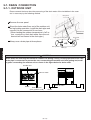
5-1 PIPING DESIGN
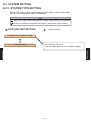
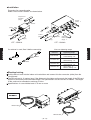
5-1-1 PIPING METHOD
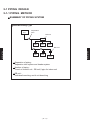
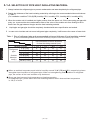
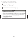
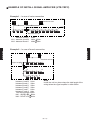
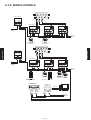
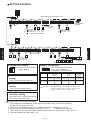
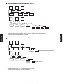
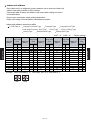
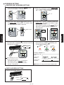
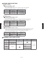
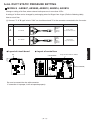
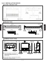
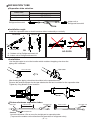
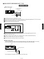
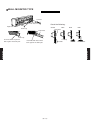
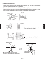
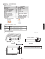
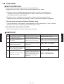
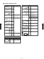
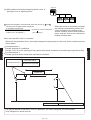
SUMMARY OF PIPING SYSTEM
Heat Recovery Type
Outdoor
unit
Separation
tube
RB unit
Indoor
unit
Indoor
unit
Indoor
unit
Indoor
unit
Indoor
unit
Indoor
unit
Separation of piping :
Separation tube system and header system
Number of piping :
3 each of outdoor unit - RB unit,2 pipe for indoor unit
RB unit :
Individual branching and 4 unit branching
- (05 - 01) -
INSTALLATION
INSTALLATION
RB unit
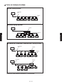
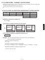
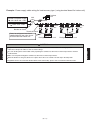
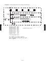
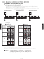
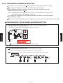
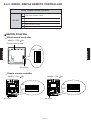
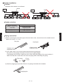
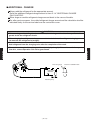
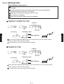
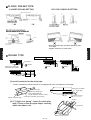
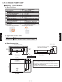
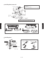
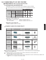
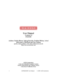
TYPE OF PIPING SYSTEM
Line Piping System
Outdoor
unit
Separation
tube
RB unit
Indoor
unit
Indoor
unit
Indoor
unit
Indoor
unit
Indoor
unit
Indoor
unit
Header Piping System
Header
Outdoor
unit
INSTALLATION
Indoor
unit
Indoor
unit
Indoor
unit
Indoor
unit
Indoor
unit
Indoor
unit
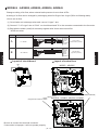
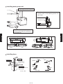
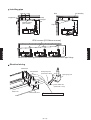
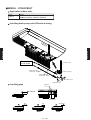
Combined (Separation tube/Header) Piping System
Outdoor
unit
Separation
tube
Header
RB unit
Indoor
unit
Outdoor
unit
Indoor
unit
Indoor
unit
Indoor
unit
Separation
tube
Indoor
unit
RB unit
Indoor
unit
Indoor
unit
Indoor
unit
Indoor
unit
Indoor
unit
Indoor
unit
Separation after header separation is not possible
- (05 - 02) -
Indoor
unit
INSTALLATION
RB unit
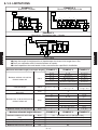
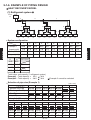
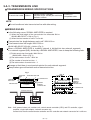
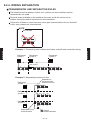
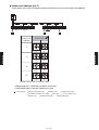
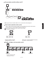
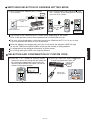
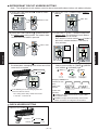
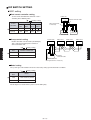
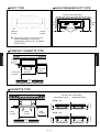
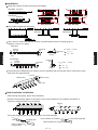
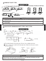
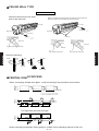
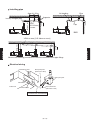
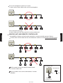
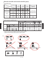
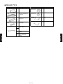
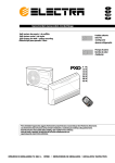
5-1-2. LIMITATIONS
EXAMPLE 2
Branch kit : Separation tube
EXAMPLE 1
Branch kit : Header
Outdoor
unit
Outdoor
unit
a
a
b
H1
b
c
RB
unit
Indoor
unit
d
RB
unit
Indoor
unit
e
RB
unit
H3
Indoor
unit
H2
RB
unit
d
e
f
g
RB
unit
c
H1
h
Indoor
unit
H4, f
i
RB
unit
Indoor
unit
j
RB
unit
Indoor
unit
RB
unit
Indoor
unit
k
RB
unit
Indoor
unit
H3
H2
RB
unit
H4
Indoor
unit
Indoor
unit
EXAMPLE 3
Branch kit : Separation tube + Header
Outdoor
unit
b
a
RB unit
4 branch
H1
g
H3
d
e
H4
f
i
RB
h unit
RB
unit
Indoor
unit
Indoor
unit
H2
Indoor
unit
Indoor
unit
Indoor
unit
Indoor
unit
INSTALLATION
INSTALLATION
c
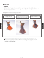
CAUTIONS
● Keep the length of straight portion of pipe between two branch kits longer than 0.5m.
● Don't use separation tube in the downstream of header.
● Install separation tube and header in the corrent direction specified in installation.
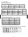
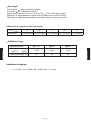
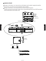
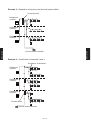
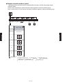
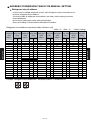
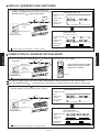
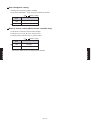
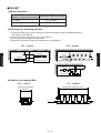
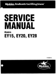
Maximum allowable length (actual pipe length)
Between outdoor unit and the
farthest indoor unit
100 m
Total pipe length
200 m
Between outdoor unit and the 1st
branch kit
70 m
Between the 1st branch kit and the
farthest indoor unit
40 m
Between indoor unit and RB unit
40 m
Maximum allowable height difference
Between outdoor unit and indoor
units
Between indoor units
Between RB units
Between RB unit and indoor unit
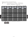
EXAMPLE 1
EXAMPLE 2
EXAMPLE 3
a+b
a+c
a+d
a+e
-
a+g
a+g+h
a+b+h
a+g+i
a+b+c+i
a+b+c
a+b+c+d+j
a+b+d
a+b+c+d+e+k
a+b+e
a+b+c+d+ e+f
a+b+f
a+b+c+d+e+f+g a+b+c+d+e
a+b+c+d+e
+h+i+j+k
+f+g+h+i
a
b
c
d
e
f
g
b+h
b+c+i
b+c+d+j
b+c+d+e+k
b+c+d+ e+f
g+h
g+i
b+c
b+d
b+e
b+f
c, d, e, f
EXAMPLE 1
EXAMPLE 2
EXAMPLE 3
50 m
40 m
15 m
15 m
5m
H1
H1
- (05 - 03) -
(If outdoor unit is in the upper side)
(If outdoor unit is in the lower side)
H2
H3
H4
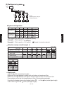
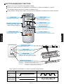
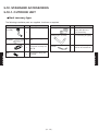
5-1-3. PIPE SIZE
HEAT RECOVERY MODEL
Pipe size connected to outdoor unit.
(unit : mm)
Suction Gas
Pipe size
Model
AO 90
Discharge Gas
Pipe size
28.58
Liquid Pipe size
19.05
12.70
Between two adjacent refrigerant branch kits.
Total model code of
indoor unit
Suction Gas
Pipe size
(unit : mm)
Discharge Gas
Pipe size
Liquid Pipe size
Less than 30
15.88
12.70
9.52
31 or more to 60
19.05
15.88
9.52
61 or more
28.58
19.05
12.70
Separation Kit
UTR-BP54MA
UTR-BP90MA
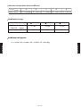
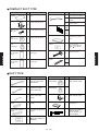
Connection pipe size of indoor unit.
Model code of indoor unit
INSTALLATION
INSTALLATION
"Total model code of indoor unit" is the total value for the indoor unit model code connected downstream.
(unit : mm)
Gas Pipe size
Liquid Pipe size
7, 9
9.52
6.35
12, 14
12.70
6.35
18, 20, 24, 25
15.88
30
36, 45, 54, 60
15.88
19.05
6.35
9.52
9.52
A part of V series indoor units are required adaptor for connecting pipes.
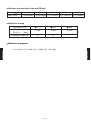
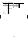
PIPE DIAMETER, RECOMMENDED MATERIAL AND WALL THICKNESS
Nominal Diameter
(in)
1/4"
3/8"
1/2"
5/8"
3/4"
1-1/8"
Outside Diameter
(mm)
6.35
9.52
12.70
15.88
19.05
28.58
COPPER
JIS H3300 C1220T-O or equivalent
Material
Wall Thickness
(mm)
0.8
0.8
0.8
1.0
Design pressure : 2.94MPa G.
Please select the pipe size in accordance with local rules.
- (05 - 04) -
1.0
1.2
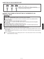
5-1-4. SELECTION OF PIPE HEAT INSULATING MATERIAL
1. Always insulate the refrigerant pipe to prevent condensation and water droplets by the refrigerant pipe.
2. Decide the thickness of the heat insulating material by referring to the recommended minimum thickness
in Table 1.
(For installation condition T=32 C(DB),humidity<70%, humidity<75%, humidity<80%, humidity<85%)
3. When the outdoor unit is installed at a higher position than the indoor unit, fill the connecting part gap with
putty, etc. to prevent the dew condensation water of the valve of the outdoor unit from flowing to the indoors from the gap between the pipe and the heat insulating material.
4.
Liquid pipe and gas pipe should be completely insulated with same specification and sealed.
5. In case not to insulate and not to seal refrigerant pipe completely, it will become the cause of water leak.
Table 1 Size of refrigerant pipe and recommended minimum thickness of heat insulating material
(In case a heat insulating material which thermal conductivity is equal to or less than 0.040 W/(m·k) is used. )
INSTALLATION
Relative humidity
Refrigerant
pipe
6.35 (1/4")
9.52 (3/8")
< 70%
8
9
Outside
diameter
mm(in)
12.70 (1/2")
15.88 (5/8")
19.05 (3/4")
28.58 (1 1/8")
10
10
10
11
< 75%
10
11
< 80%
13
14
< 85%
17
18
12
12
13
14
15
16
16
18
19
20
21
23
When an ambient temperature and relative humidity exceed 32 C (DB)and>85%, respectively please
strengthen heat insulation of refrigerant pipe. When not strengthening heat insulation of refrigerant
pipe, the surface of the heat insulation may be dewed.
Since gas pipe becomes high temperature at heating operation,
for heatpump type, please select the heat insulating material which heat-resistant temperature
is 120 C or more.
- (05 - 05) -
INSTALLATION
Recommended minimum thickness
for heat insulating material (mm)
5-1-5. ADDITIONAL CHARGE CALCULATION
Additional refrigerant charge amount is calculated according to calculated value from its pipe length
of liquid pipe and additional amount for outdoor unit.
Round up the calculated result to two decimal places.
CALCULATION OF ADDITIONAL REFRIGERANT CHARGE AMOUNT
Model
Factory charged
amount (kg)
A
Additional amount
for outdoor unit (kg)
AOÜ90MPCMF
11.8
1.2
Diameter of liquid
pipe (mm)
B
Additional amount for
pipe length (kg/m)
6.35
9.52
12.70
0.025
0.063
0.136
Additional amount for outdoor unit
A = 1.2 (kg)
B=
Total length x 0.136
of Ø12.70mm
kg/m
liquid pipe
+
Total length x 0.063
of Ø9.52mm
kg/m
liquid pipe
m
+
Total length x 0.025
of Ø6.35mm
kg/m
liquid pipe
m
kg
m
kg
kg
Calculation of additional refrigerant charge amount
C=A+B
Example : When the liquid pipe length are 20m (Ø12.70mm), 15m (Ø9.52mm),
and 20m (Ø6.35mm), respectively.
Additional amount for outdoor unit :
A = 1.2 kg
Calculation of additional amount for pipe length :
B = 20(m) x 0.136(kg/m) +15(m) x 0.063(kg/m) + 20(m) x 0.025(kg/m) = 4.17(kg)
Calculation of additional refrigerant charge amount :
1.2 kg + 4.17 kg = 5.37 kg
- (05 - 06) -
INSTALLATION
INSTALLATION
Calculation of additional amount for pipe length
5-1-6. EXAMPLE OF PIPING DESIGN
HEAT RECOVERY MODEL
(1) Refrigerant system
Outdoor
unit
AO90
a
b
c
B
A
d
RB
unit
C
f
e
RB
unit
D
g
h
i
j
RB
unit
E
k
l
m n
o
p
q
1
2
3
4
5
6
7
8
9
10
11
12
Indoor
unit
Indoor
unit
Indoor
unit
Indoor
unit
Indoor
unit
Indoor
unit
Indoor
unit
Indoor
unit
Indoor
unit
Indoor
unit
Indoor
unit
Indoor
unit
Example 1
INSTALLATION
Capacity(kW)
Example 2
Capacity(kW)
11
12
AU9
AU9
2.8
2.8
1
2
3
4
5
6
7
8
9
10
AU9
AU9
AU9
AU9
AU7
AU7
AU7
AU7
AU7
AU7
2.8
2.8
2.8
2.8
2.2
2.2
2.2
2.2
2.2
2.2
AU9
AU9
AU9
AU9
AU7
AU7
AU7
AU7
AU7
AU7
2.8
2.8
2.8
2.8
2.2
2.2
2.2
2.2
2.2
2.2
Total capacity
30.0
AU25 AU25
7.05
7.05
38.5
Total indoor unit capacity (1 refrigerant system)
36.4
Example1 : Total capacity = 30.0
Example2 : Total capacity = 38.5
36.4
Example 2 cannot be selected
Selection of pipe size (Example 1)
Suction Gas Pipe
Discharge Gas Pipe
Gas Pipe
Liquid Pipe
Length [m] (Example)
(unit : mm)
a
28.58
b
19.05
c
19.05
d
19.05
e
15.88
19.05
15.88
15.88
15.88
12.70
f
g
9.52
9.52
12.70
9.52
9.52
9.52
9.52
6.35
6.35
10
10
15
5
5
10
5
h
i
j
k
l
m
n
o
p
q
9.52
6.35
9.52
6.35
9.52
6.35
9.52
6.35
9.52
9.52
9.52
9.52
9.52
9.52
5
10
10
5
6.35
5
6.35
10
6.35
10
6.35
5
6.35
5
6.35
10
- (05 - 07) -
INSTALLATION
System configuration
Pipe length
a+b+c+q=45
100m (actual pipe length)
b+c+q=35
40m (actual pipe length)
a+b+c+d+e+f+g+h+i+j+k+l+m+n+o+p+q=135
200m (total pipe length)
Difference in height between outdoor unit and indoor units maximum 50m.
Difference in height between highest and lowest indoor unit maximum 15m.
Selection of separation tube and header
A
Model name
B
C
D
E
UTR-BP90MA UTR-BP54MA UTF-Y90A4A UTF-Y90A4A UTF-Y90A4A
Liquid pipe (mm)
INSTALLATION
Additional refrigerant
(R407C)
(kg/m)
Liquid pipe length (m)
¿ 12.70
¿ 9.52
¿ 6.35
0.136
0.063
0.025
10
35
90
Additional refrigerant
1.2 + (0.136 x 10) + (0.063 x 35) + (0.025 x 90) = 7.02 (kg)
- (05 - 08) -
INSTALLATION
Additional charge
(2) Refrigerant system
Outdoor
unit
AO90
a
A
b
B
c
RB
unit
d
C
f
RB
unit
D
RB
unit
g
e
RB
unit
E
h
i
1
2
3
4
Indoor
unit
Indoor
unit
Indoor
unit
Indoor
unit
NOTE:
Liquid pipe does not pass
through theRB unit
System configuration
1
2
3
4
Total capacity
Example 1 AR18 AR18 AR30 AR36
5.3
Capacity(kW)
5.3
8.8
10.5
29.9
8.8
Capacity(kW)
8.8
8.8
12.7
39.1
INSTALLATION
INSTALLATION
Example 2 AR30 AR30 AR30 AR45
Total capacity of indoor unit (1 refrigerant system)
Example1 : Total capacity = 29.9 36.4
Example2 : Total capacity = 39.1 36.4
Example 2 cannot be selected.
Selection of pipe size (Example 1)
Suction Gas Pipe
Discharge Gas Pipe
Gas Pipe
Liquid Pipe
Length [m] (Example)
h
a
28.58
19.05
12.70
20
(unit : mm)
b
15.88
12.70
c
15.88
12.70
6.35
10
6.35
5
d
15.88
12.70
9.52
5
e
19.05
15.88
9.52
10
f
15.88
6.35
2
g
15.88
6.35
2
i
15.88
19.05
9.52
2
9.52
2
Pipe length
a+b=32m 100m (actual pipe length)
Difference in height between outdoor unit and indoor unit maximum 50m.
Difference in height between the highest and the lowest indoor unit maximum 15m.
Form outdoor unit to the first header tube a=20m 70m (actual pipe length)
From the first header tube to the farthest indoor unit e=12m 40m (actual pipe length)
200m (total pipe length)
a+b+c+d+e+f+g+h+i=58
- (05 - 09) -
Selection of separation tube and RB unit
A
Model name
B
C
D
E
UTR-HD906R UTF-Y54A1A UTF-Y54A1A UTF-Y54A1A UTF-Y54A1A
Additional charge
Liquid pipe (mm)
Additional refrigerant
(R407C)
(kg/m)
Liquid pipe length (m)
¿ 12.70
¿ 9.52
¿ 6.35
0.136
0.063
0.025
20
19
19
Additional refrigerant
INSTALLATION
INSTALLATION
1.2 + (0.136 x 20) + (0.063 x 19) + (0.025 x 19) = 5.60 (kg)
- (05 - 10) -
(3) Refrigerant system
Outdoor
unit
AO90
b
a
A
B
c
e
d
NOTE:
Liquid pipe do not pass
C
through the RB unit C and D
f
RB
unit
RB
unit
RB
unit
E
D
h
g
i
j
k
1
2
3
4
5
6
Indoor
unit
Indoor
unit
Indoor
unit
Indoor
unit
Indoor
unit
Indoor
unit
System configuration
1
2
3
Example 1 AW24 AB36 AR9
6.9
Capacity (kW)
10.5
2.8
4
5
6
AR9
AR9
AR9
2.8
2.8
2.8
Total capacity
28.6
8.0
Capacity (kW)
14.1
4.0
4.0
4.0
4.0
38.1
INSTALLATION
INSTALLATION
Example 2 AW30 AB54 AR14 AR14 AR14 AR14
Total capacity of indoor unit (1 refrigerant system)
Example1 : Total capacity = 28.6 36.4
Example2 : Total capacity = 38.1 36.4
Example 2 cannot be selected.
Selection of pipe size (Example 1)
Suction Gas Pipe
Discharge Gas Pipe
Gas Pipe
Liquid Pipe
Length[m](Example)
a
28.58
19.05
12.70
10
h
i
j
k
9.52
6.35
10
9.52
6.35
5
9.52
6.35
5
9.52
6.35
10
b
(unit : mm)
c
19.05
15.88
9.52
20
19.05
15.88
9.52
5
d
15.88
12.70
6.35
5
e
19.05
15.88
9.52
10
f
15.88
6.35
2
Pipe length
a+b+k = 40 100m (actual pipe length)
b+k = 30 40m (actual pipe length)
a+b+c+d+e+f+g+h+i+j+k= 84
200m (total pipe length)
Difference in height between outdoor unit and indoor units maximum 50m.
Difference in height between highest and lowest indoor unit maximum 15m.
- (05 - 11) -
g
19.05
9.52
2
Selection of separation tube and RB unit
A
Model name
B
C
UTR-BP90MA UTR-BP54MA UTF-Y54A1A
D
E
UTF-Y54A1A
UTF-Y90A4A
Additional charge
Liquid pipe (mm)
¿ 12.70
¿ 9.52
¿ 6.35
Additional refrigerant
(R407C)
(kg/m)
0.136
0.063
0.025
Liquid pipe length (m)
10
37
37
Additional refrigerant
INSTALLATION
INSTALLATION
1.2 + (0.136 x 10) + (0.063 x 37) + (0.025 x 37) = 5.82 (kg)
- (05 - 12) -
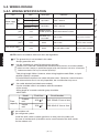
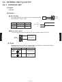
5-2. WIRING DESIGN
5-2-1. WIRING SPECIFICATION
Use
Size
Outdoor
Power supply unit
2
cable (mm )
Indoor
unit
Maximum
8.0
Minimum
6.0
Maximum
2.5
Minimum
1.5
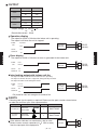
Transmission cable
2
(mm )
0.33
Remote controller cable
2
(mm )
0.33
Remote controller cable
2
(mm )
0.33
External input cable
2
(mm )
0.33
Wire type
Remarks
H07RN-F or
equivalent
Three phase, 50Hz, 380-415V
4 Wire + Ground
H07RN-F or
equivalent
Single phase, 50Hz, 220-240V
1
2
2 Wire + Ground
Shielded Level 4 Non-polar, Twisted pair,
22AWG (0.65mm) Solid core diameter 0.65mm
Sheathed vinyl
cord cable
3
Polar 3-core
Wired remote controller
Simple remote controller
Shield
Polar 3-core
Group remote controller
External switch controller
Shield
Twist pair polar 2-core
External switch controller
4
1,2 The ground wire is not included in this cable.
Always ground the unit.
3
Use the shielded wire specified and always ground it.
22AWG Level 4 cable with shielded(National Electrical Manufacturers Association (NEMA)
**differs from the Category 4 specification proposed by the Electronic Industries Association/
Telecommunication Industry Association (EIA/TIA)**
Total wiring length 2000m. However, when wiring length exceeds 500m, a signal
amplifier (option) is required.
Do not bundle the transmission cable with other wires. Otherwise, transmit-receive
with a transmission line is not only impossible, but a malfunction may occur.
4
10m cable attached.(excluded some models)
Use the shielded cable in accordance with the standards
of the country.
Wiring length of a remote controller group should be
within 500m.
Model
Fuse
capacity
5
6
Field fuse
Circuit breaker
Outdoor
unit
40A
5
40A 100mA 0.1sec or less
Indoor
unit
20A
6
20A 40mA 0.1sec or less
per outdoor unit
per refrigerant system.
Install the knife switch (contact gap 3mm or more) near the indoor unit
for ease of maintenance.(A breaker can be used instead of the knife swicth
for the outdoor unit.
- (05 - 13) -
INSTALLATION
INSTALLATION
NOTE:Install in accordance with local rules and regulations.
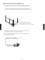
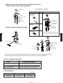
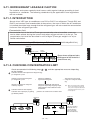
5-2-2. POWER SUPPLY CABLE WIRING
POWER SUPPLY CABLE SPECIFICATION
A separated power supply cable must be provided for the outdoor unit and indoor unit.
Outdoor unit : 3 4W 50Hz 380 - 415V
Indoor unit : 1
50Hz 220 - 240V
Use a circuit breaker of 40A or more for every outdoor unit.
The indoor unit shall be connected up to one refrigerant system, and a circuit breaker
of 20A or more should be used.
CAUTION
1. Above "Wire size" and "Fuse capacity" are minimum value.
2. Regulation of wire size and circuit breaker differs from each locality, please refer in accordance with local rules.
3. Specific wiring requirement should be applied Type 245 IEC 57 or equivalent.
4. To prevent the electrical noise malufunction and hazards from insulation failure, the unit should be connected to ground.
6. When connecting the indoor unit power supply from part of a 3-phase power source, recommend to take the power
from each phase uniformly to prevent unbalance
7. All field wiring and components must be provided by a licensed electrician.
8. Use copper conductors only.
- (05 - 14) -
INSTALLATION
INSTALLATION
5. A disconnect switch may be required for ease of maintenance in accordance with local regulation for each unit.
Please check the local rules and regulations.
Make the wire length between disconnect switch and unit terminal as short as possible.
Example : Power supply cable wiring for heat recovery type. (using terminal board for indoor unit)
Outdoor
unit
40A
Outdoor unit power supply
3 4W 50Hz 380 - 415V
20A
Indoor unit power supply
1 50Hz 220 - 240V
Breaker on hand
Indoor
unit
Indoor
unit
Terminal board
Power for refrigerant branchunit
supplied directly from relay circuit
on circuit board of indoor unit.
Refrigerant branch unit
Refrigerant branch unit
CAUTION
First, turn off the power to the indoor unit by operating the control unit, converter or external input device and then
cut the breaker.
Make sure to operate through the control unit, converter or external input device.
When the breaker is designed, locate it at a place where the users cannot start and stop in the daily work.
Regulation of wire size and circuit breaker differs from each locality, please refer in accordance with local rules.
- (05 - 15) -
INSTALLATION
INSTALLATION
Except for EMERGENCY, never turn off main as well as sub breaker of the indoor units during operation.
It will cause compressor failure as well as water leakage.
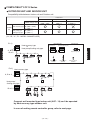
5-2-3. TRANSMISSION LINE
TRANSMISSION WIRING SPECIFICATIONS
Use
Size
Wire type
22AWG LEVEL 4 (NEMA)
non-polar 2core, twisted pair solid core
diameter 0.65mm
Transmission cable 0.33mm 2
Remarks
LONWORKS ®
compatible cable
NOTE
Do not bundle and wire transmission line with other wiring.
WIRING RULES
In the following cases, SIGNAL AMPLIFIER is required.
(1) When the total length of the transmission line exceeded 500 m.
AB+BC+BD+DE+EF > 500 m (Fig. 1)
(2) When the total number of units* is over 64.
Transmission line length between each unit*: MAX 400 m.
Total transmission line length: MAX 2000 m
When a SIGNAL AMPLIFIER is installed, network is divided into two network segments.
In a network segment (NS), divided by a SIGNAL AMPLIFIER, have to keep the following facts.
(1)Total transmission line length: MAX 500 m
AB+BC+BD < 500 m (Fig. 2)
(2)The total number of units* : MAX 64
INSTALLATION
INSTALLATION
AB+BC+BD+DE+EF+EG+GH < 2000 m (Fig. 2)
(3)The number of terminal resistor : 1
(4)The total number of control units : 2
Arrange so that there is one terminal resistor for each network segment.
Always take a ground from both ends of transmission line.
Fig. 1
OUTDOOR
UNIT
B
A
TERMINAL
RESISTOR
C
E
D
INDOOR UNIT
Fig. 2
TRANSMISSION LINE
SIGNAL AMPLIFIER
is required.
OUTDOOR
UNIT
PC CONTROLLER
F
B
CENTRAL
REMOTE
CONTROLLER
A
TRANSMISSION LINE
C
D
TERMINAL RESISTOR NS 2
E
F
G
Transmission Line
NS 3
INDOOR UNIT
1
2
E
TRANSMISSION
1
2
E
TRANSMISSION
Indoor unit
Indoor unit
NS 1
TERMINAL
RESISTOR
CENTRAL
REMOTE
CONTROLLER
PC CONTROLLER
NS 4
H
SIGNAL AMPLIFIER
Note : Unit* means indoor unit, outdoor unit, central remote controller (CRC) and PC controller, signal
amplifier, single split adaptor, network convertor etc..
Control units means central remote controller and PC controller ant network convertor for LONWORKS.
- (05 - 16) -
CHECK POINT
Arrange so that there is no transmission cord between each network segment except the
transmission cord which passed through the signal amplifier.
Arrange so that there is one terminal resistor for each network segment.
If necessary,remove the terminal resistor which connected temporarily to the CN22 terminator
of the circuit board for the outdoor unit.
Fig. 3
NS 1
OUTDOOR
UNIT
A
TRANSMISSION CORD
C
B
D
TERMINAL RESISTOR NS 2
E
F
G
NS 3
INDOOR UNIT
CENTRAL
REMOTE
CONTROLLER
PC CONTROLLER
NS 4
H
SIGNAL AMPLIFIER
FUSE(3A)
1 2 E E 1 A 2 1B 2 E
POWER TRANSMISSION
TERMINAL TERMINAL
1 2 3 1 2 E
2 1 E
RC TRANSMISSION POWER
TERMINAL
TERM.A TERM.B
SIGNAL AMPLIFIER
INDOOR UNIT
SW7
TERMINAL
RESISTOR
SW3 SW2 SW1
TERMINAL
RESISTOR
CN2
E1
SW9 SW8
123
12E
21E
RC TRANSMISSION POWER
TERMINAL
C
N
2
2
ACIN
OUTDOOR BOARD
OUTDOOR UNIT
TERMINAL RESISTOR
INDOOR UNIT
- (05 - 17) -
INDOOR UNIT
INSTALLATION
NS 3 NS 4
SWITCH
CN22
INSTALLATION
1 50Hz
220-240V
TERMINAL
RESISTOR
EXAMPLE OF INSTALL SIGNAL AMPLIFIER (UTR-YRPC)
Example 1 : In case of series connection
NS1
Terminal resister
A
B Signal amplifier
C
NS2
Terminal resister
between A and C
NS1 : between A and B
NS2 : between B and C
800m
400m 500m
400m 500m
A
Terminal resister
B
Signal amplifier
D
C
Terminal resister
G
E
F
between A and B
between B and C
between B and D
between D and E
between E and F
between E and G
Total wiring length
NS1 : AB+BC+BD
NS2 : DE+EF+EG
100m
200m
200m
200m
100m
100m
900m
500m
500m
Note
Install the unit in a place where the total length of the
wiring below the signal amplifier is within 500m.
- (05 - 18) -
INSTALLATION
INSTALLATION
Example 2 : In case of branch connection
Example 3 : Branch connection and in case of over 64 units
Terminal
resistor
NS1
A
Terminal
box
B
I
NS2
Signal amplifier
Terminal resistor
C
G
H
D
1
2
63 64
3
NS3
Signal amplifier
Terminal resistor
E
between A and B 100m
between B and C 100m
between B and D 200m
between C and E 500m
between C and F 100m
between C and G 100m
between B and H
10m
between C and I
10m
Number of indoor unit 64
Total wiring length 1100m
NS1 : AB+BC+CG+CF+BH+CI
500m
NS2 : Total equipments between H and D
NS3 : IE 500m
- (05 - 19) -
64
INSTALLATION
INSTALLATION
F
5-2-4. WIRING SEPARATION
TRANSMISSION LINE SEPARATION RULES
The transmission line between indoor unit, outdoor unit and controllers can be
connected by one cable.
Terminal board available on the market or the ones inside the indoor unit or
outdoor should be used for transmission line separation.
Connection of three or more lines may cause poor communication for one terminal.
In this case, please use a terminal box.
NOTE
Do not loop.
Refrigerant
system 1
Refrigerant
system 2
Refrigerant
system 3
Signal amplifier
Example 2 : Separating transmission line.
Refrigerant
system 1
Separate on
the terminal for
transmission line.
Refrigerant
system 2
Refrigerant
system 3
Separation using
terminal board
Central
remote controller
- (05 - 20) -
INSTALLATION
INSTALLATION
Example 1 : Connecting each outdoor and indoor unit with one connection wiring.
Example 3 : Separation wiring from one terminal board radially.
Terminal board
Refrigerant
system 1
Refrigerant
system 2
Central remote controller
Example 4 : Combination of example 2 and 3
Possible to 16 branches
Refrigerant
system 1
Refrigerant
system 2
Refrigerant
system 3
Terminal board
Central remote controller
- (05 - 21) -
INSTALLATION
INSTALLATION
Refrigerant
system 3
5-2-5. WIRING EXAMPLE
REFRIGERANT BRANCH UNIT
OUTDOOR UNIT
Terminal
Power
Terminal
Transmission
RS T NE
E1 2
INDOOR UNIT
INDOOR UNIT
CN6
Connector
Terminal
Trans- Power
RC mission
3 4W 50Hz
380-415V
12 3
12E
2 1
E
INDOOR UNIT
CN6
Connector
CN6
Connector
Terminal
Trans- Power
RC mission
2 1
1 2 3
Terminal
Trans- Power
RC mission
12 3
1 2E
E
1 2E
2 1
E
1 50Hz
220-240V
WIRED REMOTE
CONTROLLER
WIRED REMOTE
CONTROLLER
REFRIGERANT BRANCH UNIT
Power
Terminal
Transmission
RS TNE
E1 2
Terminal
INDOOR UNIT
INDOOR UNIT
3 4W 50Hz
380-415V
INDOOR UNIT
CN6
CN6
INSTALLATION
INSTALLATION
OUTDOOR UNIT
CN6
Connector
Terminal
Trans- Power
RC mission
Connector
Terminal
Trans- Power
RC mission
Connector
Terminal
Trans- Power
RC mission
12 3
1 2 3
1 2 3
12E
2 1
E
1 2E
2 1
E
1 2E
2 1
E
1 50Hz
220-240V
2 REMOTE CONTROLLER
WIRELESS REMOTE
CONTROLLER
2 REMOTE CONTROLLER
CENTRAL REMOTE
CONTROLLER
TRANSMISSION
ADAPTOR
RS-232C
Terminal
Transmission
E 2
1
Terminal
Power
E 2 1
Terminal
Transmission
E 2 1
Terminal
Power
PC CONTROLLER
E2 1
50Hz
{1220-240V
- (05 - 22) -
5-3. SYSTEM SETTING
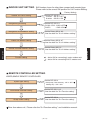
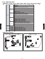
5-3-1. SYSTEM TYPE SETTING
Set the DIP switch to the corresponding system type as shown in the table.
Do not use a nonexistent switch combination.
Note
Perform the system setting and address setting , before turning on the power.
For the air conditioner to operate satisfactorily, perform the correct setting.
OUTDOOR UNIT SETTING
(
. . . Factory Setting)
Refrigerant circuit address setting
INSTALLATION
Set the Rotary SW 8 & 9
See the switch detail for "5-3-2 Address setting"
INSTALLATION
Function setting
- (05 - 23) -
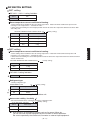
SW Number shows for other than compact wall mounted type.
Please refer to the correct SW position for 5-4 Function Setting.
(
Outdoor unit series setting
Set the DIP SW 5-3
V series : SW 5-3 OFF
S series : SW 5-3 ON 1
Refrigerant type setting
Set the DIP SW 2-3
R410A / R22 : SW2-3 OFF
R407C
: SW2-3 ON 2
Refrigerant circuit address setting
Set the Rotary SW 8 & 9
See the detail for "5-3-2 Address setting"
Indoor unit address setting
Set the Rotary SW 6 & 7
See the detail for "5-3-2 Address setting"
Remote controller address setting
INSTALLATION
. . . Factory Setting)
Set the Rotary SW 10
See the detail for "5-3-2 Address setting"
1 : Set to ON for connecting S series outdoor unit.
Function setting
2 : Set to ON for connecting R407C outdoor unit.
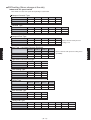
REMOTE CONTROLLER SETTING
WIRED,SIMPLE REMOTE CONTROLLER
System type setting
Set the DIP SW 4
Heat pump / Heat recovery : SW 4 OFF
Cooling only : SW 4 ON
Dual remote controller setting
Set the DIP SW 1 & 2
See the detail for "5-4 Function setting"
Group control setting
Set the DIP SW 3
See the detail for "5-4 Function setting"
Other than above unit , Please refer the "5-4 Function setting " and installation manual.
- (05 - 24) -
INSTALLATION
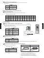
INDOOR UNIT SETTING
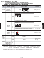
5-3-2. ADDRESS SETTING
For this system, each address should be preset before operation.
Please refer following table for outdoor unit, indoor unit each remote controller.
KINDS OF ADDRESS AND SETTING RANGE
SW 9
B C DE
F0 1
A
B C DE
A
789
99
F0 1
3 456
Setting
example
0
REMARKS
2
0
TYPE OF SWITCH
3 456
Refrigerant
circuit address
SETTING
RANGE
2
Outdoor
unit
SETTING
789
UNIT
Arbitrary numbers can be
set in range of 00-99
SW 8
B C DE
A
789
789
SW 9
3 456
A
F0 1
2
99
3 456
0
F0 1
2
Refrigerant
circuit address
B C DE
Manual address setting
PCB Type A 1
Arbitrary numbers can be
set in range of 00-99
SW 8
Infrared address setting
After turning on the power, the wireless remote controller can
be used to set the address. For details, refer to “5-3-4".
Set this switch to 00 at factory shipment.
Arbitrary numbers can be
set in range of 00-63
4
SW 6
A
15
5-3-3
F0 1
3 456
00
See the setting method
2
789
Remote
controller
address
B C DE
Infrared address setting
After turning on the power, the wireless remote controller can
be used to set the address. For details, refer to “5-3-4".
Set this switch to 00 at factory shipment.
PCB Type A 1
Set from 0 to 15 in sequence
SW 10
Dual remote
ON/OFF
Wired,
controller switch
Simple
remote
controller Number of indoor
ON/OFF
unit connection
Central
Central remote
remote
controller
address
controller
Group
Group remote
remote
controller
address
controller
1 PCB Type A :
DIP SW 1,2
OFF : Not terminated
ON : Terminated
Number of indoor unit
DIP SW 3
OFF : 1 unit
ON : multiple units
0
15
Initial setting
0
3
Initial setting
Compact Cassette Type
Cassette Type
Compact Duct Type
Low Static Pressure Duct Type
Duct Type
Floor / Ceiling Type
Ceiling Type
Wall Mounted Type
Ceiling Wall Type
4 Indoor unit address can be set up to 63. However maximum connectable indoor unit is 16 units
- (05 - 25) -
INSTALLATION
A
B C DE
A
789
INSTALLATION
789
SW 7
3 456
63
4
F0 1
2
0
3 456
Indoor unit
address
F0 1
2
Indoor
unit
B C DE
Manual address setting
PCB Type A 1
SETTING EXAMPLE
Set1
0
Transmission line (Non-polar 2 core)
Set5
Set2 Set3 Set4
Set2 Set3 Set4
Set2 Set3 Set4
Set2 Set3 Set4
Set2 Set3 Set4
Set2 Set3 Set4
Set2 Set3 Set4
Set2 Set3 Set4
0 0 0
0 1 1
0 2 0
0 3 0
0 4 0
0 5 1
0 14 0
0 15 0
Central remote
controller
2 Indoor units
(Max.16)
Set8
Set9
DIP-SW1 OFF
DIP-SW2 OFF
DIP-SW3 OFF
ON
ON
OFF
ON
OFF
ON
Set8
Set9
DIP-SW1-1 ON
DIP-SW1-2 OFF
DIP-SW1-4 OFF
2 Remote controllers
Set1
Set2 Set3 Set4
Set2 Set3 Set4
Set2 Set3 Set4
Set2 Set3 Set4
Set2 Set3 Set4
Set2 Set3 Set4
Set2 Set3 Set4
63 0 0
63 1 0
63 2 0
63 3 1
63 4 2
63 5 0
63 6 0
63 7 0
INSTALLATION
Set2 Set3 Set4
3 Indoor units
Set8
Set9
Set6
DIP-SW1 ON
DIP-SW2 OFF
DIP-SW3 ON
00
Set7
Set7
Set7
Set7
00
01
02
03
Network
convertor
Group remote controller (Max.4)
Outdoor unit setting
Set1
63
Set1: Refrigerant circuit address
(Rotary SW9,8)
Indoor unit setting
Set2 Set3 Set4
63 6 0
Set2: Refrigerant circuit address
Set3: Indoor unit address
Set4: Remote controller address
Set2
Refrigerant
circuit address
Central remote controller
setting
Set5: Controller address (Max.16)
Set7: Controller address (Max.4)
Set4
Indoor unit
address
Remote
controller
address
Second digit
First digit
Second digit
First digit
First digit
Rotary SW 9
Rotary SW 8
Rotary SW 7
Rotary SW 6
Rotary SW 10
1
PCB TYPE A
Group remote controller
setting
Set3
1 : PCB TYPE A : Compact Cassette type Cassette type Compact Duct type
Low Static Pressure Duct type Duct type Floor/Ceiling type
Ceiling type Wall Mounted type Ceiling Wall type
Wired, Simple remote
controller setting
Set8: Dual remote controller (DIP-SW1,2)
Set9: Group control (DIP-SW3)
Instructions for setting up the address
1. The refrigerant circuit address of the indoor and outdoor units can be set to optional
numbers in the range of 0 to 99.
2. The Indoor unit address can be set to optional numbers in the range of 0 to 63.
3. Set the remote controller address in the order of 0,1,2, . . . ,15.(Blank is not allowed)
4. The central remote controller address can be set to optional numbers in the range of 0 to 15.
5. The total numbers of indoor units <
= 16.
- (05 - 26) -
INSTALLATION
63
5-3-3. MANUAL ADDRESS SETTING METHOD
ADDRESS SETTING DESCRIPTION
Refrigerant circuit address (set 1)
In case of 2 or more refrigerant system in VRF network system, each refrigerant system
should be set an exclusive refrigerant circuit address.
Refrigerant system : It means same refrigerant circuit which has connected between outdoor
unit and indoor unit by piping.
Refrigerant system 1
Refrigerant system 2
1
Refrigerant system 25
2
1 00 0
1 01 1
1 02 2
25
2 00 0
2 01 1
2 02 2
25 00 0
25 01 1
25 02 2
Example
B C DE
A
B C DE
A
A
789
789
789
B
F0 1
F0 1
F0 1
F0 1
A
A
789
A
789
789
789
F0 1
A
A
789
789
A
3 456
3 456
3 456
789
A
2
2
2
3 456
789
3
2
Please refer to the conversion table
50
B C DE
9
F0 1
B C DE
1
B C DE
9
F0 1
2
1
F0 1
3 456
3 456
3 456
A
2
2
2
3 456
25
B C DE
0
B C DE
B
B C DE
0
3 456
3 456
A
2
2
11
3
2
Please refer to the conversion table
Setting range 00 - 99(Arbitrary numbers can be set)
All the indoor unit and outdoor unit in same refrigerant circuit should be set same address.
1 PCB Type A :
Compact Cassette Type
Cassette Type
Compact Duct Type
Duct Type
Floor / Ceiling Type
Low Static Pressure Duct Type
Ceiling Type
Wall Mounted Type
Ceiling Wall Type
- (05 - 27) -
INSTALLATION
B C DE
A
B C DE
A
B C DE
F0 1
3 456
B C DE
A
F0 1
B C DE
1
789
B C DE
A
0
2
B C DE
789
1
F0 1
2
B C DE
F0 1
3 456
3 456
3 456
789
INSTALLATION
F0 1
2
2
1
1
Rotary SW 9 Rotary SW 8
2
F0 1
PCB TYPE A
F0 1
3 456
50
Refrigerant
circuit
address
0
2
25
F0 1
3 456
11
Rotary SW 9 Rotary SW 8
2
1
SW setting
789
Refrigerant
circuit
address
Indoor unit
789
Outdoor unit
Indoor unit address (set 3)
Each indoor unit in same refrigerant system should be set an exclusive indoor unit address.
1
1 02 2
PCB TYPE A
address
Rotary SW 7 Rotary SW 6
B C DE
A
B C DE
A
A
789
F0 1
A
789
789
E
B C DE
A
B C DE
3 456
3 456
789
2
F0 1
2
F0 1
A
3 456
A
2
3 456
B C DE
B
F0 1
2
0
3 456
3 456
789
B C DE
A
F0 1
2
B C DE
789
3
F0 1
3 456
0
2
B C DE
F0 1
1
789
47
1 15 0
2
3 456
30
2
11
F0 1
1 14 1
1
Indoor unit
3
INSTALLATION
1 13 0
2
F
Please refer to the conversion table
Setting range 00 - 63(Arbitrary numbers can be set)
Connectable indoor units are maximum 16 units.
1 PCB Type A :
Compact Cassette Type
Cassette Type
Compact Duct Type
Duct Type
Floor / Ceiling Type
Low Static Pressure Duct Type
Ceiling Type
Wall Mounted Type
Ceiling Wall Type
- (05 - 28) -
INSTALLATION
1 01 1
789
1 00 0
Remote controller address (set 4)
1 individual remote controller can be controlled Max.16 indoor unit with connecting remote
controller cable.
These units connecting by remote controller cable regards as remote controller group.
Even 1 indoor unit as 1 or no remote controller connection regards 1 remote controller group.
0
0 00 0
0 01 1
0 02 2
0 03 3
0 04 0
0 05 0
1
INSTALLATION
B C DE
F0 1
A
3 456
0
Rotary SW 10
2
0
B C DE
3 456
A
2
1
F0 1
789
1
B C DE
3 456
A
2
11
F0 1
789
B
B C DE
3 456
A
2
15
F0 1
789
INSTALLATION
PCB TYPE A
789
Remote
controller
address
F
1 PCB Type A :
Compact Cassette Type
Cassette Type
Compact Duct Type
Duct Type
Floor / Ceiling Type
Low Static Pressure Duct Type
Ceiling Type
Wall Mounted Type
Ceiling Wall Type
- (05 - 29) -
Central remote controller address (set 5)
00
01
02
03
Central remote controller (Max. 16)
INSTALLATION
INSTALLATION
Set central remote controller address first, to conduct the initial setting of it.
Refer to the "setting manual" for details.
Network convertor address (set 6)
00
Network
convertor
Group remote controller (Max. 4)
01
Network
convertor
Rotary SW 111
Set the Rotary SW 111 on network convertor PCB.
Refer to the installation manual for details.
- (05 - 30) -
Single split AC
Group remote controller address (set 7)
Network
convertor
00
01
02
03
Group remote controller (Max. 4)
Dual remote controller switch (set 8)
When 2 sets of wired remote controllers are connected to the remote control group,
turn the DIP SW 1 and 2 of Master Remote Controller off.
Slave remote controller will not be valid for timer setting.
Last command is priority.
[Master] [Slave]
[Master]
SW1 ON
SW2 OFF
SW1 OFF ON
SW2 OFF ON
Remote controller unit PCB
Setting by DIP SW 1 and 2
When only 1 remote controller will connect,
this switch 1 must be set ON.
Number of indoor unit connection (set 9)
4
SW3 ON
2
SW3 ON
Remote controller PCB
Setting by DIP SW 3
- (05 - 31) -
1
SW3 OFF
INSTALLATION
INSTALLATION
Set group remote controller address first, to conduct the initial setting of it.
ADDRESS CONVERSION TABLE FOR MANUAL SETTING
Refrigerant circuit address
In the case of a multiple refrigerant system, each refrigerant system should be set an
exclusive refrigerant circuit address.
Conversion table of refrigerant circuit address and rotary switch setting are shown
in the table below.
Do not use a nonexistent switch setting combination.
Rotary SW setting is formed with the Hexadecimal notation.
Refrigerant circuit address conversion table (Outdoor unit)
(SW9 : "0" , SW8 : "0" - - - Factory setting)
Refrigerant Rotary Switch Refrigerant Rotary Switch Refrigerant Rotary Switch Refrigerant Rotary Switch Refrigerant Rotary Switch
setting
setting
setting
setting
setting
circuit
circuit
circuit
circuit
circuit
address
address
address
address
address
0
0
0
0
0
0
0
0
0
0
0
0
0
0
0
0
1
1
1
1
0
1
2
3
4
5
6
7
8
9
A
B
C
D
E
F
0
1
2
3
20
21
22
23
24
25
26
27
28
29
30
31
32
33
34
35
36
37
38
39
1
1
1
1
1
1
1
1
1
1
1
1
2
2
2
2
2
2
2
2
4
5
6
7
8
9
A
B
C
D
E
F
0
1
2
3
4
5
6
7
SW9 SW8
40
41
42
43
44
45
46
47
48
49
50
51
52
53
54
55
56
57
58
59
2
2
2
2
2
2
2
2
3
3
3
3
3
3
3
3
3
3
3
3
8
9
A
B
C
D
E
F
0
1
2
3
4
5
6
7
8
9
A
B
SW9 SW8
60
61
62
63
64
65
66
67
68
69
70
71
72
73
74
75
76
77
78
79
3
3
3
3
4
4
4
4
4
4
4
4
4
4
4
4
4
4
4
4
B C DE
A
A
3 456
3 456
789
SW9
F0 1
2
F0 1
2
B C DE
Example : Refrigerant circuit address 30 : Set Rotary SW9 to "1" and SW8 to "E"
SW8
- (05 - 32) -
C
D
E
F
0
1
2
3
4
5
6
7
8
9
A
B
C
D
E
F
SW9 SW8
80
81
82
83
84
85
86
87
88
89
90
91
92
93
94
95
96
97
98
99
5
5
5
5
5
5
5
5
5
5
5
5
5
5
5
5
6
6
6
6
0
1
2
3
4
5
6
7
8
9
A
B
C
D
E
F
0
1
2
3
INSTALLATION
0
1
2
3
4
5
6
7
8
9
10
11
12
13
14
15
16
17
18
19
SW9 SW8
789
INSTALLATION
SW9 SW8
Refrigerant circuit address conversion table (Indoor unit)
1 PCB Type A :
Compact Cassette Type
Cassette Type
Low Static Pressure Duct Type
Ceiling Type
Compact Duct Type
Duct Type
Wall Mounted Type
Floor / Ceiling Type
Ceiling Wall Type
(SW9 : "0" , SW8 : "0" - - - Factory setting)
Refrigerant Rotary Switch Refrigerant Rotary Switch Refrigerant Rotary Switch Refrigerant Rotary Switch Refrigerant Rotary Switch
setting
setting
setting
setting
setting
circuit
circuit
circuit
circuit
circuit
address
address
address
address
address
0
0
0
0
0
0
0
0
0
0
0
0
0
0
0
0
1
1
1
1
0
1
2
3
4
5
6
7
8
9
A
B
C
D
E
F
0
1
2
3
20
21
22
23
24
25
26
27
28
29
30
31
32
33
34
35
36
37
38
39
1
1
1
1
1
1
1
1
1
1
1
1
2
2
2
2
2
2
2
2
4
5
6
7
8
9
A
B
C
D
E
F
0
1
2
3
4
5
6
7
SW9 SW8
40
41
42
43
44
45
46
47
48
49
50
51
52
53
54
55
56
57
58
59
2
2
2
2
2
2
2
2
3
3
3
3
3
3
3
3
3
3
3
3
8
9
A
B
C
D
E
F
0
1
2
3
4
5
6
7
8
9
A
B
SW9 SW8
60
61
62
63
64
65
66
67
68
69
70
71
72
73
74
75
76
77
78
79
3
3
3
3
4
4
4
4
4
4
4
4
4
4
4
4
4
4
4
4
B C DE
A
A
3 456
3 456
789
SW9
F0 1
2
F0 1
2
B C DE
Example : Refrigerant circuit address 30 : Set Rotary SW9 to "1" and SW8 to "E"
SW8
- (05 - 33) -
C
D
E
F
0
1
2
3
4
5
6
7
8
9
A
B
C
D
E
F
SW9 SW8
80
81
82
83
84
85
86
87
88
89
90
91
92
93
94
95
96
97
98
99
5
5
5
5
5
5
5
5
5
5
5
5
5
5
5
5
6
6
6
6
0
1
2
3
4
5
6
7
8
9
A
B
C
D
E
F
0
1
2
3
INSTALLATION
0
1
2
3
4
5
6
7
8
9
10
11
12
13
14
15
16
17
18
19
SW9 SW8
789
INSTALLATION
SW9 SW8
Indoor unit address
Each indoor unit in a refrigerant system should be set an exclusive indoor unit
address with rotary switches or DIP switches.
Conversion table of indoor unit address and rotary switch setting are shown
in the table below.
Do not use a nonexistent switch setting combination.
Rotary SW setting is formed with the Hexadecimal notation
Indoor unit address conversion table
1 PCB Type A :
Compact Cassette Type
Cassette Type
Low Static Pressure Duct Type
Ceiling Type
Compact Duct Type
Duct Type
Wall Mounted Type
Floor / Ceiling Type
Ceiling Wall Type
(SW7 : "0" , SW6 : "0" - - - Factory setting)
Rotary Switch
Rotary Switch
Rotary Switch
Rotary Switch
Rotary Switch
Indoor unit
Indoor unit
Indoor unit
Indoor unit
setting
setting
setting
setting
setting
address
0
1
2
3
4
5
6
7
8
9
10
11
12
0
0
0
0
0
0
0
0
0
0
0
0
0
SW7 SW6
0
1
2
3
4
5
6
7
8
9
A
B
C
13
14
15
16
17
18
19
20
21
22
23
24
25
0
0
0
1
1
1
1
1
1
1
1
1
1
D
E
F
0
1
2
3
4
5
6
7
8
9
address
SW7 SW6
26
27
28
29
30
31
32
33
34
35
36
37
38
1
1
1
1
1
1
2
2
2
2
2
2
2
A
B
C
D
E
F
0
1
2
3
4
5
6
B C DE
A
B C DE
A
3 456
3 456
789
SW7
F0 1
2
2
F0 1
SW6
- (05 - 34) -
address
SW7 SW6
39
40
41
42
43
44
45
46
47
48
49
50
51
Example : Indoor unit address 15 : Set Rotary SW7 to "0" and SW6 to "F"
789
INSTALLATION
SW7 SW6
address
2
2
2
2
2
2
2
2
2
3
3
3
3
7
8
9
A
B
C
D
E
F
0
1
2
3
SW7 SW6
52
53
54
55
56
57
58
59
60
61
62
63
3
3
3
3
3
3
3
3
3
3
3
3
4
5
6
7
8
9
A
B
C
D
E
F
INSTALLATION
Indoor unit
address
5-3-4. INFRARED ADDRESS SETTING
A wireless remote controller (UTB- VB) is required to set the infrared address setting.
This function is available in all indoor unit with infrared signal receiver.
Infrared address setting for duct type models can be made possible by using the
optional IR receiver unit (UTB- WA).
Note : Since Beeping sound generate from indoor unit PCB installed far away (not from
IR Receiver unit), sound might not be heard.
The indoor unit’s refrigerant circuit address and indoor unit address can be set using the
infrared address setting.
When remote controller address setting is required, set by the rotary switch on the indoor unit’s PCB.
PREPARATION FOR INFRARED ADDRESS SETTING
(1) Set the switch on the indoor unit’s PCB that is used for manual address
setting is set to “00” at factory setting.
A
INSTALLATION
A
SW2
789
SW1
F0 1
3 456
SW6 SW7
B C DE
SW9
SW8
SW3 SW4 SW5
2
INSTALLATION
789
SW10
CN27
3 456
CN22 CN21
CN23 CN24
F0 1
2
B C DE
(This process is unnecessary for newly installed and not yet set the SW.)
setting "00"
Check the position "0"
(Factory setting)
If it is set to any other numbers, that setting value will be enabled.
(2) Turn on the power to the indoor unit.
By turning on the power indoor units initializes EEV, so make sure the piping
air-tight test and vacuuming have been conducted before turning on the power.
Also check again to make sure no wiring mistakes were made before turning on the power.
Breaker ON
20A
Indoor
units
- (05 - 35) -
Indoor
unit
SWITCHING SELECTION OF ADDRESS SETTING MODE
(3) Press and hold the “MANUAL/AUTO” button
for 3 seconds.
Pi Pi Pi
(4) Press and hold the “FAN CONTROL ” and
the “+” buttons. Whilst holding these 2 buttons,
press the "ACL" button.
OPERATION
OPERATION
indicator (Red)
LAMP
FAN CONTROL
SET TEMP
(+)
MANUAL AUTO
ACL
IR RECEIVER UNIT
Address setting
mode display
The position of the “MANUAL/AUTO” button varies depending on the model.
Refer to the operation manual for the position that is included with the unit.
The error will be displayed by continuosly pressing the "MANUAL/AUTO" for 10 sec or more.
In this case release the button or turn off the power.
An explanation of the displayed information as shown below.
As a Ceiling Wall type, LAMP color might be different.
SELECTION AND CONFIRMATION OF CUSTOM CODE
(5) Press the “+” or “-” buttons to select the custom
code that matches the setting with the indoor unit.
By selecting the appropriate custom code, the
communication between the indoor unit and the
wireless RC become possible.
(6) Press the “VERTICAL AIRFLOW "button
to send the code to the indoor unit.
Correct code:
Pi Pi
CUSTOM CODE
( - - - )
A
The initial setting is " "
- (05 - 36) -
Wrong code:
No Response
INSTALLATION
INSTALLATION
When the address has already been set in the circuit board, the operation LAMP will light
up and the TIMER and SWING LAMPs will display the number of setting address.
BUTTON NAME AND FUNCTION
Refer to “5-3-2" for an outline of the address setting.
It does not matter whether the refrigerant circuit address or indoor unit address is set first.
(The method shown here sets the indoor unit address first.)
During address setting mode, indoor unit reject the any operation command from remote controller.
Address data
SLEEP button
Address setting number
Confirmation of address setting.
* Indoor unit address valid range 00-63
Refrigerant circut address valid range 00-99
Address code
MASTER CONTROL button
01 --- Indoor unit address
02 --- Refrigerant circuit address
- Start the address setting mode
- Changes the address display digits
FAN MODE button
Switches between the address data (top line)
and address code (bottom line)
START/STOP button
"+" and "-" button
Transmits address setting
INSTALLATION
INSTALLATION
Increases and decreases the displayed number
IR RECEIVER UNIT
OPERATION LAMP
SWING
OPERATION
TIMER
SWING
Indication of address code
TIMER LAMP
Indication of address data number (1 degit)
SWING LAMP
Indication of address data number (10 degit)
* IR Reciver unit is not shown for swing mark
MANUAL/AUTO button
Long push ----- Switches between the address setting mode and
(3 sec more) the address setting complete mode.
Short push ----- Switches the indicator display (between the indoor
unit address and refrigerant circuit address)
Note : Address code display is as follows (operation lamp display)
OPERATION LAMP
INDOOR UNIT ADDRESS DISPLAY
ON
ON
ADDRESS SETTING
MODE
OFF
ADDRESS SETTING
COMPLETE MODE
OFF
REFRIGERANT CIRCUIT ADDRESS DISPLAY
OFF
(Light continuously)
(Light 3 sec ON / 1 sec OFF)
ON
ON
OFF
(Light OFF)
- (05 - 37) -
(Light 0.5 sec ON / 0.5 sec OFF)
ADDRESS SETTING
INDOOR UNIT ADDRESS SETTING
(7) Press the “MASTER CONTROL
to access the address setting mode.
” button
(8) Make sure the bottom number address code
is ‘01’. If the number is other than ‘01’, press
the “+” or the “-” buttons to alter.
SET "01"
(10) Press the “+” or the “-” buttons to adjust the
address data. The indoor unit address range
is between 00 and 63.
Each time the master control
button is
pressed, it switches between 1 unit and 10
units positions.
INSTALLATION
Address data
Change degit
Range
00 - 63
+ : UP
- : DOWN
(11) Press the “START/STOP ” button once to send
the information. A beeping noise will be heard if the
command is accepted.
Pi Pi
Pi PiPiPi
(12) Indoor unit will display the indoor unit address
data number on "TIMER "(GREEN) and
"SWING "(ORANGE) light.
OPERATION
(RED)
continuously
TIMER
(GREEN)
SWING
(ORANGE)
Flashing times of
address numbers
(1 degit)
Flashing times of
address numbers
(10 degit)
(Example) ADDRESS : 15
OPERATION LAMP
(RED)
TIMER LAMP
(GREEN)
In the following cases the setting signal is not
read and a buzzer sounds.
The indoor unit address No. is set out of range
(64 or more) : Pi Pi Pi
(3 sec)
SWING LAMP
(ORANGE)
The setting of the rotary switch on the PCB is
not "00" : Pi Pi Pi Pi Pi
(13) Press the “SLEEP” button.
PiPi
WRONG: Pi
5 times
1 - 10 sec
0.5sec ON / 0.5sec OFF
1 times
1 - 10 sec
ADDRESS 0 setting will not indicate TIMER LAMP.
CHECK ADDRESS SETTING
PiPi
CORRECT : Pi
0.5sec ON / 0.5sec OFF
PiPiPiPiPi
(3 sec)
- (05 - 38) -
INSTALLATION
(9) Press the “FAN CONTROL ” button to access
the address data setting mode. The address data
will flash once this button is pressed.
REFRIGERANT CIRCUIT ADDRESS SETTING
Note : The refrigerant circuit address can also be set evenwhile above indoor unit address display.
” button to select
(15) Press the "+" or "-" button to adjust address
code 02.
SET "02"
Address code
(16) Press the “FAN CONTROL ” button to access
the address data setting mode. The address data
will flash once this button is pressed.
(17) Press the “+” or the “-” buttons to adjust the
address data. The refrigerant circuit address
range is between 00 and 99.
Each time the "master control
" button is
pressed, it switches between 1 unit and 10
units positions.
INSTALLATION
Address data
Change digit
Range
00 - 99
+ : UP
- : DOWN
(18) Press the “START/STOP ” button once to send
the information. A beeping noise will be heard if the
command is accepted.
(19) Indoor unit will display the refrigerant circuit
address data number on "TIMER "(GREEN)
and "SWING "(ORANGE) light.
OPERATION
(RED)
Pi Pi
Pi PiPiPi
3 sec ON
1 sec OFF
TIMER
(GREEN)
SWING
(ORANGE)
Flashing times of
address numbers
(1 degit)
Flashing times of
address numbers
(10 degit)
(Example) ADDRESS : 25
OPERATION LAMP
(RED)
TIMER LAMP
(GREEN)
In the following cases the setting signal is not
read and a buzzer sounds.
SWING LAMP
(ORANGE)
The setting of the rotary switch on the PCB
is not "00" : Pi Pi Pi Pi Pi
” button.
PiPi
CORRECT : Pi
PiPi
WRONG: Pi
5 times
1 - 10 sec
0.5sec ON / 0.5sec OFF
2 times
1 - 10 sec
ADDRESS 0 setting will not indicate TIMER LAMP
and SWING LAMP.
ADDRESS display will automatically switched from
indoor unit address to refrigerant circuit address.
CHECK ADDRESS SETTING
(20) Press the “SLEEP
0.5sec ON / 0.5sec OFF
PiPiPiPiPi
(3 sec)
- (05 - 39) -
INSTALLATION
(14) Press the “FAN CONTROL
the address code.
DISPLAY ADDRESS CODE SWITCHING
(21) Address display switches between indoor unit
address and refrigerant circuit address by pressing
"MANUAL/AUTO
" button once shortly.
Pi
Indoor unit address
OPERATION LAMP : ON
OPERATION LAMP
(RED)
TIMER LAMP
(GREEN)
OPERATION
1 - 10 sec
5 times
0.5sec ON / 0.5sec OFF
SWING LAMP
(ORANGE)
OPERATION
indicator (Red)
0.5sec ON / 0.5sec OFF
1 times
1 - 10 sec
LAMP
Refrigerant circuit address
OPERATION LAMP :
3 sec ON / 1 sec OFF
MANUAL AUTO
IR RECEIVER UNIT
OPERATION LAMP
(RED)
TIMER LAMP
(GREEN)
0.5sec ON / 0.5sec OFF
5 times
1 - 10 sec
0.5sec ON / 0.5sec OFF
SWING LAMP
(ORANGE)
2 times
1 - 10 sec
Check to make sure the address setting is correct.
(22) Press and hold the “MANUAL/AUTO
3 seconds.
” button for
(23) Press the “ACL” button.
OPERATION
After pressing the ACL button,
please set the custom code
again if b,c,d setting.
Pi Pi Pi
OPERATION
indicator (Red)
LAMP
* Operation lamp
change displays
MANUAL AUTO
ACL
IR RECEIVER UNIT
Timer lamp keep blinks the number of times of address No.
The address setting signal is not received afer switched address setting completion mode. (Pi Pi Pi Pi Pi)
Press the "MANUAL/AUTO
" button again for 3 sec to return to if required to return the address setting mode.
(24) Press “MANUAL/AUTO
” button shortly to select
the both address to be checked correct setting
Indoor unit address
OPERATION LAMP : OFF
OPERATION LAMP
(RED)
TIMER LAMP
(GREEN)
OPERATION
1 - 10 sec
5 times
0.5sec ON / 0.5sec OFF
SWING LAMP
(ORANGE)
OPERATION
indicator (Red)
1 times
LAMP
MANUAL AUTO
0.5sec ON / 0.5sec OFF
1 - 10 sec
Refrigerant circuit address
OPERATION LAMP :
0.5 sec ON / 0.5 sec OFF
IR RECEIVER UNIT
OPERATION LAMP
(RED)
TIMER LAMP
(GREEN)
SWING LAMP
(ORANGE)
Check to make sure the address setting is correct.
- (05 - 40) -
0.5sec ON / 0.5sec OFF
1 - 10 sec
5 times
0.5sec ON / 0.5sec OFF
2 times
1 - 10 sec
INSTALLATION
INSTALLATION
COMPLETION OF ADDRESS SETTING MODE
SETTING UP EACH INDOOR UNIT
01-01
01-02
01-03
Repeat steps (1) through to (24). Steps (1) through to
(6) and (21) to (24) only need to carried out if the custom code
is different to the factory setting of “A”.
RESET THE POWER AFTER SETTING UP ADDRESS OF ALL
INDOOR UNITS
Important
If the reset is not performed, address can not be read in normally.
The set address is stored in the PCB and will remain in memory even when the power
is turned off.
However setting address is effective after power reset.
Record the address set in the indoor unit on a label, etc., and affix the label to the unit
so it can be used for after-sales service operations.
Address 0 setting will not indicate TIMER LAMP and SWING LAMP.
Once the "ACL" button is pressed on the remote controller, the MASTER CONTROL will be set in the
"AUTO MODE".
Please adjust the MASTER CONTROL to either "COOLING" or "HEATING" before trying to operate
the air conditioner.
Note : If CUSTOM CODE is set to anything other than "A" ,the remote control must be set accordingly
to the INDOOR UNIT setting.
- (05 - 41) -
INSTALLATION
INSTALLATION
After all the addresses have been set, the circuit breaker needs to be switched off for
at least 2 minutes.
After the 2 minutes has passed, power can be restored.
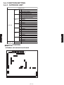
5-4. FUNCTION SETTING
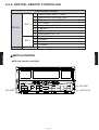
5-4-1. OUTDOOR UNIT
Outdoor unit
SW 2
SW 3
SW 4
DIP SW
SW 5
SW 7
SW 8
SW 9
ROTARY SW
Forbidden
Forbidden
Base heater validity / invalidity
Forbidden
Forbidden
Forbidden
Forbidden
Forbidden
System type switch 1
System type switch 2
Forbidden
Forbidden
Refrigeration circuit address 1
Refrigeration circuit address 2
SWITCH POSITION
Outdoor unit control circuit board
9
8
Rotary-SW
7
6
5
4
3
2 Dip- SW1
CN50CN49
CN48
CN22
CN5
INSTALLATION
SW 6
Test run(Cooling)
Test run(Heating)
Pump down operation
Forced defrost operation
Silent operation fan mode
Snow falling protection fan mode
EEV initialize
Forced oil recovery operation
Forbidden
Forbidden
Forbidden
Forbidden
Forbidden
Forbidden
Forbidden
Forbidden
INSTALLATION
1
2
3
4
1
2
3
4
1
2
3
4
1
2
3
4
1
2
3
4
1
2
3
4
1
2
3
4
SW 1
- (05 - 42) -
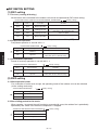
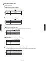
DIP SWITCH SETTING
(1) SW1 setting
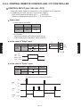
1-1 Test run ( cooling & Heating )
All the indoor units connected to the outdoor unit can be test-operated by DIP switch setting.
SELECTOR SWITCH FOR TEST RUN AND NORMAL OPERATION (
SW1-1
SW1-2
Test Run
Remarks
OFF
OFF
Normal operation
ON
OFF
Cooling test run
(OFF-ON) and (operated continuously
more than 1 min. with ON state)
OFF
ON
Heating test run
Same as above
ON
ON
Normal operation
(when release ON
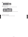
1-2 Pump down operation
Pump down operation is set with SW1- 3
PUMP DOWN OPERATION (
SW1-3
Pump down operation
OFF
Release
ON
Operate
OFF)
Factory setting)
Remarks
(OFF-ON) and (operated continuously
more than 30 sec. with ON state)
1-3 Forced defrost operation
Forced oil recovery operation is set with SW1- 4
FORCED DEFROST OPERATION
SW1-4
(
Factory setting)
Forced defrost
OFF
Release
ON
Operate
Remarks
(OFF-ON) and (operated continuously
more than 30 sec. with ON state)
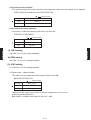
(2) SW2 setting
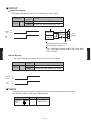
2-1 Silent operation mode
For a reduction of noise level at night, the operating mode of the outdoor unit can be switched.
(In the cooling mode only.)
SILENT OPERATION MODE
(
SW 2-1
Silent operation mode
OFF
Release
ON
Operate
Factory setting)
2-2 Snow falling protection fan mode
When snowing , to prevent the unit from being covered with snow, the outdoor fan is periodically
operated by this switch even when the compressor is stopped.
SNOW FALLING PROTECTION FAN MODE (
SW2-2
Snow falling protection fan mode
OFF
Release
ON
Operate
Factory setting)
- (05 - 43) -
INSTALLATION
INSTALLATION
Factory setting)
2-3 Expansion valve initialize
This switch initializes the number of pulses of the expansion valve when the outdoor unit is stopped.
ELECTRONIC EXPANSION VALVE INITIALIZATION
(
DIP SW2-3
Initialization
OFF
Release
ON
Operate
Factory setting)
2-4 Forced oil recoverry operation.
Oil recovery is started manually by DIP SW 2-4 on the PCB.
FORCED OIL RECOVERY
Factory setting)
DIP SW2-4
Forced oil recovery
OFF
Release
ON
Operate
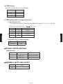
(3). SW3 setting
INSTALLATION
INSTALLATION
(
Dip SW3-1,3-2,3-3,3-4 setting forbidden.
(4).SW4 setting
Dip SW4-1,4-2,4-3,4-4 setting forbidden.
(5). SW5 setting
5-1 Dip SW 5-1,5-2,5-4 setting forbidden
5-2 Base heater validity/invalidity
This switch sets the output of the base heater (CN5) on the PCB.
BASE HEATER SWITCH
(
DIP SW5-3
Factory setting)
Base heater
OFF
Invalidity
ON
validity
The base heater output turns ON at an outside temperature of 2 C or less
and during heating operation.
Base heater : available in the field 220-240V AC , 35W
- (05 - 44) -
(6) SW6 setting
DIP SW 6-1,6-2,6-3 and 6-4 setting forbidden
DIP SW6-1
OFF
DIP SW6-2
OFF
DIP SW6-3
OFF
DIP SW6-4
OFF
(7) SW7 setting (Never change at the site)
7-1 System type switch
The outdoor unit model can be selected by setting DIP switches 7-2 and 7-1 on the PCB.
(
OUTDOOR UNIT TYPE SELECTION
SW7-2
Type selection
OFF
OFF
Forbidden
ON
OFF
Forbidden
OFF
ON
Heat recovery
ON
ON
Forbidden
INSTALLATION
INSTALLATION
SW7-1
Factory setting)
7-2 Dip SW 7-3 & 7-4 setting forbidden
DIP SW7-3
OFF
DIP SW7-4
OFF
ROTARY SWITCH SETTING
SW8,9 setting
Rotary SW
8
9
Description
Refrigerant circuit
address SW 1
Refrigerant circuit
address SW 2
Remarks
Refrigerant circuit
address (the first digit)
Refrigerant circuit
address (the second digit)
EXTERNAL INPUT AND OUTPUT
Connector
Output
CN48
Error Display (DC12V)
- (05 - 45) -
5-4-2. INDOOR UNIT
MODELS : AUXB, AU A, ARXB, ARXA, ARXC, AB A, AS A18-30, AW A
1 Forbidden
SW 1
2 Forbidden
3 Room temp correct coefficient of heating 1
4 Room temp correct coefficient of heating 2
1 Room temp correct coefficient of cooling
SW 2
2 Forbidden
3 Refrigerant type
4 Auto restart validity / invalidity
1 Forbidden (Indoor unit fan speed switch 1)
DIP-SW
SW 3
2 Forbidden (Indoor unit fan speed switch 2)
3 Forbidden (Indoor unit fan speed switch 3)
4 External input select edge / pulse
1 Forbidden (Indoor unit model code)
SW 4
2 Forbidden (Indoor unit model code)
3 Forbidden (Indoor unit model code)
4 Forbidden (Indoor unit model code)
1 Wireless remote controller custom code switch 1
2 Wireless remote controller custom code switch 2
3 Outdoor unit series setting
4 Draft prevention setting switch
Rotary SW
SW 6
Indoor unit address switch 1
SW 7
Indoor unit address switch 2
SW 8
Refrigerant circuit address switch 1
SW 9
Refrigerant circuit address switch 2
SW 10
Remote controller address switch
INSTALLATION
INSTALLATION
SW 5
SWITCH POSITION
AUXB, AU A, ARXB, ARXA, AB A
AS A18-30, AW A
CN24
CN23
CN22
CN21
CN22 CN21
SW10
CN27
CN23 CN24
SW1
SW9
SW8
SW2
SW6 SW4
SW8 SW10
SW3 SW4 SW5
SW6 SW7
SW1
SW9 SW5
SW7 SW3
SW2
- (05 - 46) -
DIP SWITCH SETTING
SW1 setting
DIP-SW1-1, SW1-2 setting forbidden
SW1-1
OFF
SW1-2
OFF
Room temperature correct coefficient of heating.
Set the heating correct coefficient value for setting temperature. Indoor unit will be continued to operate until
reaching to "Set Temperature" + "Coeffecient value".
It takes effect for mounting the unit at higher position in order to correct the temperature difference between floor
and ceiling side.
HEATING TEMPERATURE CORRECTION (
SW1-3
SW1-4
Coefficient value
OFF
OFF
+ 4 deg
ON
OFF
+ 8 deg
OFF
ON
0 deg
ON
ON
- 2 deg
Factory setting)
INSTALLATION
Room temperature correct coefficient of cooling.
Set the cooling correct coefficient value for setting temperature. Indoor unit will be continued to operate until
reaching to "Set Temperature" + "Coeffecient value".
It takes effect for mounting the unit on floor position in order to correct the temperature defference between human
around and floor side.
COOLING TEMPERATURE CORRECTION (
SW2-1
Factory setting)
Coefficient value
OFF
0 deg
ON
+ 2 deg
DIP-SW2-2 setting forbidden
OFF
SW2-2
Refrigerant type
Selecting refrigerant type
REFRIGERNT TYPE
1
(
SW2-3
Refrigerant type
OFF
R410A / R22
ON
R407C
Factory setting)
1 : Set to ON for connecting R407C outdoor unit.
Auto restart validity / invalidity
2
Auto restart function can be selected by turning this switch ON / OFF.
(
Factory setting)
AUTO RESTART SETTING
SW2-4
Auto restart
OFF
Invalidity
ON
Validity
2 : Auto restart is an emergency function such as for power failure etc.
Do not start and stop the equipment by this function in normal operation.
Be sure to operate by the control unit, converter or external input equipment.
- (05 - 47) -
INSTALLATION
SW2 setting
SW3 setting (Never change at the site)
Indoor unit fan speed switch
This switch can select fan speed corresponding to each model.
Compact Cassette Type
SW 3-1
SW 3-2
SW 3-3
AUXB07
OFF
AUXB09
OFF
AUXB12
OFF
AUXB14
OFF
AUXB18
OFF
OFF
OFF
OFF
OFF
OFF
OFF
OFF
OFF
OFF
OFF
AU*A20
ON
ON
ON
AU*A25
OFF
ON
ON
AU*A30
OFF
OFF
ON
AU*A36
OFF
ON
OFF
AU*A45
ON
OFF
OFF
AU*A54
OFF
OFF
OFF
ARXB07
OFF
OFF
OFF
ARXB09
OFF
OFF
OFF
ARXB12
OFF
OFF
OFF
ARXB14
OFF
OFF
OFF
ARXB18
OFF
OFF
OFF
Please refer for static pressure
setting 5-4-8
ARXB45
ARXA45
OFF
OFF
OFF
Please refer for static pressure setting 5-4-8
(for ARXB)
Cassette Type
SW 3-1
SW 3-2
SW 3-3
Compact Duct Type
SW 3-1
SW 3-2
SW 3-3
SW 3-1
SW 3-2
SW 3-3
ARXB25
ARXA25
OFF
OFF
OFF
ARXB30
ARXA30
OFF
OFF
OFF
ARXB36
ARXA36
OFF
OFF
OFF
ARXC36
OFF
OFF
OFF
ARXC45
OFF
OFF
OFF
ARXC60
OFF
OFF
OFF
AB*A12
OFF
OFF
OFF
AB*A14
OFF
OFF
OFF
AB*A18
OFF
OFF
OFF
AB*A30
OFF
OFF
OFF
AB*A36
OFF
ON
OFF
AB*A45
OFF
OFF
ON
AS*A18
OFF
OFF
ON
AS*A24
OFF
ON
ON
AS*A30
ON
ON
ON
AW*A07
OFF
OFF
OFF
AW*A09
ON
OFF
OFF
AW*A12
OFF
ON
OFF
High Static Pressure Duct type
SW 3-1
SW 3-2
SW 3-3
Floor Ceiling Type
SW 3-1
SW 3-2
SW 3-3
Ceiling Type
SW 3-1
SW 3-2
SW 3-3
AB*A54
OFF
ON
ON
Wall mounted Type
SW 3-1
SW 3-2
SW 3-3
Ceiling Wall Type
SW 3-1
SW 3-2
SW 3-3
- (05 - 48) -
AW*A14
ON
ON
OFF
AW*A18
OFF
OFF
ON
AW*A24
OFF
ON
ON
AW*A30
ON
ON
ON
INSTALLATION
INSTALLATION
Duct Type , Low Static Pressure Duct type
External input select edge / pulse
This switch is used to select the format of external input command as shown in
the table below.
(
Factory setting)
SW3-4
External input select
OFF
Edge
ON
Pulse
SW4 setting (Never change at the site)
Indoor unit model code
This switch for changing the model code information of indoor unit PCB.
INDOOR UNIT MODEL CODE
7
9
12
14
18
20
25(24)
30
36
45
54
60
SW 4-1
OFF
ON
OFF
ON
OFF
ON
OFF
ON
OFF
ON
OFF
ON
SW 4-2
OFF
OFF
ON
ON
OFF
OFF
ON
ON
OFF
OFF
ON
ON
SW 4-3
OFF
OFF
OFF
OFF
ON
ON
ON
ON
OFF
OFF
OFF
OFF
SW 4-4
OFF
OFF
OFF
OFF
OFF
OFF
OFF
OFF
ON
ON
ON
ON
SW5 setting
Decide the custom code and restrict the type of infrared control signal, in order to prevent
mixing of multiple indoor unit signals.
INSTALLATION
INSTALLATION
Wireless remote controller custom code switch
Remote controller custom code switch
(
Factory setting)
SW5-1
SW5-2
Custom code
OFF
OFF
Type A
ON
OFF
Type B
OFF
ON
Type C
ON
ON
Type D
1
3
2
1. Press the MASTER CONTROL button for
more than five seconds to start the code
change.
2. Press the (+) or (-) button to select the
desired code.
A
B
C
D
Remote controller
3. Press the MASTER CONTROL button again
to end the code change.
Connected outdoor unit series
Selecting outdoor unit series.
(
Factory setting)
SW5-3
2
Outdoor unit series
OFF
VRF V series
ON
VRF S series
2 : Set to ON for connecting S series outdoor unit.
Draft prevention setting switch (only for cassette type)
Set the flap angle of cassette type unit.
Draft prevention switch
(
Normal position
Draft prevention position
Factory setting)
SW5-4
flap angle
OFF
Normal position
ON
Draft prevention position
Flap angle
35 - 65
Flap angle
25 - 65
An air flow direction, by moving the flap angle horizontally,
It can prevent that a cold wind directly hits.
*If air conditioning cooling operation is performed in
long time and a humid place, there is a possibility
that waterdrop may hang down from a blow-off mouth.
- (05 - 49) -
ROTARY SWITCH SETTING
SW6,7 setting
Indoor unit address switch
Sets the indoor unit addresses.
Please see "5-3-3 address setting" for type A indoor unit address conversion table.
INDOOR UNIT ADDRESS SWITCH
Rotary SW
(Factory setting SW 6: 0 SW 7: 0)
Description
Remarks
Indoor unit address
( the first digit )
Indoor unit address
(the second digit )
Indoor unit
address SW 1
Indoor unit
address SW 2
6
7
SW8,9 setting
Refrigerant circuit address switch
Sets the refrigerant circuit address.
Please see "5-3-3 address setting" for type A refrigerant circuit address conversion table.
Rotary SW
INSTALLATION
8
9
(Factory setting SW 8: 0 SW 9: 0)
Description
Remarks
Refrigerant circuit
address SW 1
Refrigerant circuit
address SW 2
Refrigerant circuit
address (the first digit)
Refrigerant circuit
address (the second digit)
SW10 setting
Remote controller address switch
When the indoor unit is wired by remote controller group, to identity the indoor unit in the remote
controller group, the number (remote controller address) in the remote controller group is set.
Set the remote controller address in the 0.1.2,~,15 order (Blank is not allowed)
REMOTE CONTROLLER ADDRESS SWITCH
(Factory setting : 0)
Rotary SW
Description
Remarks
10
Remote controller
address
Remote controller
address
EXTERNAL INPUT AND OUTPUT
Connector
Indoor unit type
CN21
Wall mounted /
Ceiling wall types
CN27
Other types
Input
Output
Remarks
CONTROL INPUT
(OPERATION / STOP)
CN22
OPERATION DISPLAY
(DC12V)
CN23
ERROR DISPLAY
(DC12V)
All types
INDOOR UNIT FAN
STATUS DISPLY(DC12V)
CN24
- (05 - 50) -
See 5-5-2
for details
INSTALLATION
REFRIGERANT CIRCUIT ADDRESS SWITCH
5-4-3. WIRED, SIMPLE REMOTE CONTROLLER
Wired, simple remote controller
DIP SW
1
2
Dual remote controller setting
3
Group control setting
4
Model setting
5
6
Auto changeover setting
Memory backup setting (Wired remote controller only)
SWITCH POSITION
Wired remote controller
MODEL : UTB - UB
Front case (back side)
OFF
ON
INSTALLATION
INSTALLATION
1
2
3
4
5
6
DIP Switch
Simple remote controller
MODEL : UTB - PB
DIP switch
ON
OFF
OFF
1
2
3
4
5
6
ON
DIP switch
- (05 - 51) -
1
2
3
4
5
6
MODEL : UTB - RA
DIP SWITCH SETTING
SW1 setting
Dual remote controller setting
Indoor unit
Set the remote controller DIP switch No.1 and 2
according to the following table.
(
Number of
remote
controller
Master unit
Factory setting)
1 2 3
Slave unit
When ground wire
is necessary
DIP-SW DIP-SW DIP-SW DIP-SW
No.1
No.2
No.1
No.2
1 (Normal)
ON
OFF
2 (Dual)
OFF
OFF
ON
Remote controller cable
ON
1 2 3
1 2 3
Master unit
Slave unit
Remote controller
Group control setting
Indoor unit 0
Number of indoor unit connection (One/Multiple)
This is switched according to the number of
connected indoor units.
1 2 3
Number of indoor unit
OFF
One unit connection
ON
Multiple unit connection
1 2 3
Remote
controller cable
Remote controller
When ground wire is necessary
Model setting
The system type of the outdoor unit can be selected by setting up DIP switch No.4 as follows.
DIP-SW
No.4
1 2 3
Indoor unit 3
1 2 3
Factory setting)
DIP-SW
No.3
(
Indoor unit 2
Factory setting)
Model
OFF
Heat Pump model or
Heat Recovery model
ON
Cooling only model
Do not forget to set to ON when system uses for cooling only.
- (05 - 52) -
INSTALLATION
INSTALLATION
(
1 2 3
Indoor unit 1
Auto changeover setting
Selecting auto changeover validity / invalidity.
Set to ON for AIRSTAGE TM(VRF system) Heat Recovery models.
(
DIP-SW
No.5
Factory setting)
Auto changeover
OFF
Invalidity
ON
Validity
Memory backup setting (Wired remote controller only)
Set to ON to use batteries for thr memory backup.
If batteries are not used, all of the settings stored
in memory will be deleted if there is a power failure.
Factory setting)
Memory backup
OFF
Invalidity
ON
Validity
Never turn it ON in the case of simple remote controller.
- (05 - 53) -
INSTALLATION
INSTALLATION
(
DIP-SW
No.6
5-4-4. GROUP REMOTE CONTROLLER
Group remote controller
DIP SW
1
Memory backup setting
2
Forbidden
SWITCH POSITION
Group remote controller
Front case (back side)
OFF
ON
1
2
ON
DIP SWITCH SETTING
SW1 setting
Set SW1 to ON to enable the memory backup.
If there is a power failure when the memory backup is enabled, the setting stored in the memory will be saved.
(
. . . Factory setting)
SW1
Memory backup
OFF
Invalidity
ON
Validity
SW2 setting : Forbidden
SW2
(
. . . Factory setting)
OFF
- (05 - 54) -
INSTALLATION
INSTALLATION
DIP switch
5-4-5. CENTRAL REMOTE CONTROLLER
Central remote controller
SW 2
DIP-SW
SW 3
1
2
3
4
5
6
7
8
1
2
3
4
External Input select Edge / pulse
Filter sign indication ON / OFF
o
o
C / F switch
RC operation prohibit function validity / invalidity
Forbidden
Forbidden
SRAM battery ON / OFF
Forbidden
Forbidden
Forbidden
Forbidden
Initial setting
SWITCH POSITION
INSTALLATION
INSTALLATION
SW 42
External Input validity / invalidity
Central remote controller
DIP SW2
SWITCH 42
DIP SW3
- (05 - 55) -
DIP SWITCH SETTING
SW2 SETTING
External input validity / invalidity
For validity / invalidity the external input function.
(
SW2-1
Factory setting)
External input function
OFF
Invalidity
ON
Validity
External input select edge / pulse
Select the external input command function.
(
SW2-2
Factory setting)
External input select
OFF
Edge
ON
Pulse
Filter sign indication ON / OFF
Filter check sign indication or not when filter check signal come from indoor unit.
(
SW2-3
Factory setting)
Filter check sign indication
OFF
Non-Display
ON
Display
C / F switch
Temperature display is centigrade( C ) / Fahrenheit( F )
(
Factory setting)
SW2-4
C/F
OFF
C
ON
F
RC operation prohibit function validity / invalidity
For validity / invalidity the wired ,simple and wireless remote controller operation prohibit function.
(
Factory setting)
SW2-5
RC operation prohibit function
OFF
Validity
ON
Invalidity
- (05 - 56) -
INSTALLATION
INSTALLATION
(Refer to 5-4-2 and 5-4-3 external input & output)
SW2-6 2-7 setting forbidden.
SW 2-6
OFF
SW 2-7
OFF
SRAM battery ON / OFF
When installing the central remote controller, this switch must be set to ON.
(factory setting : OFF)
(
Factory setting)
SW2-8
SRAM Battery
OFF
OFF
ON
ON
At the time of shipment, the battery is turned off to avoid electricity consumption.
Be sure to set this switch to ON.
This switch is used when initializing the central remote controller.
- (05 - 57) -
INSTALLATION
INSTALLATION
SW42 Initial setting button
5-4-6. DUCT STATIC PRESSURE SETTING
MODELS : ARXB07, ARXB09, ARXB12, ARXB14, ARXB18
Change a setting of air flow, when external static pressure is more than 25 Pa.
A setting of air flow can be changed by exchanging wires for B type from A type. (Refer to following table)
How to set air flow
(1) Connect "1" of "B type" wire to "CN4" on circuit board and "2" to the connector connected to the fan motor.
TYPE
WIRE
EXTERNAL STATIC PRESSURE
REMARK
1
2
A
0 - 25 Pa
1
2
3
4
1
2
3
4
5
BLUE
VIOLET
PINK
WHITE
BLACK
1
2
3
4
5
6
VIOLET
PINK
BLUE
RED
WHITE
BLACK
Factory setting
(Standard static pressure)
5
2
B
25 - 50 Pa
1
3
2
4
5
INSTALLATION
6
Layout of circuit board
Standard parts
(High static pressure)
Layout of control box
CN4
CIRCUIT BOARD
Change this wire TYPE A to TYPE B
CN4
WIRE (FAN MOTOR)
Be sure to connect the wire with connector.
If connection is improper, it will not operate properly.
- (05 - 58) -
INSTALLATION
1
MODELS : ARXB25, ARXB30, ARXB36, ARXB45
Change a setting of air flow, when external static pressure is more than 40 Pa.
A setting of air flow can be changed by exchanging wires for B type from A type.(Refer to following table)
How to set air flow
(1) Cut a binder not to damage wires and remove "A type " wire.
(2) Connect "1" of "b type" wire to "CN4" on circuit board and "2" to the connector connected to the fan motor.
(3) Bind with the binder (small) of accessory together with *three wires bound first.
*AR25:two wires
WIRE
EXTERNAL STATIC PRESSURE
1
A
0 - 40 Pa
2
1
2
3
4
5
2
1
B
INSTALLATION
REMARK
40 - 80 Pa
1
2
3
4
5
6
Layout of circuit board
1
2
3
4
5
BLACK
WHITE
PINK
PURPLE
BLUE
Factory setting
(Standard static pressure)
1
2
3
4
5
6
BLACK
WHITE
RED
BLUE
PINK
PURPLE
Standard parts
(High static pressure)
Layout of control box
CN4
INSTALLATION
TYPE
MODEL : ARXB25
WIRE (FAN MOTOR)
MODELS : ARXB30, ARXB36, ARXB45
Change this wire TYPE A to TYPE B
Be sure to connect the wire with connector.
If connection is improper, it will not operate properly.
- (05 - 59) -
5-5. EXTERNAL INPUT & OUTPUT
5-5-1. OUTDOOR UNIT
(1) Input
Not use
(2) Output
+
1 Error display
This output indicates the outdoor unit and connected indoor
unit's "Normal" or "Error" status.
CONNECTOR OUTPUT VOLTAGE
CN48
(BLACK)
Normal
12V
Error
1
2
P.C.B
CN 48
-
(BLACK)
Error
STATUS
0V
Error
Indicator
CN48
Normal
12V
0V
2 Base heater output
CN 5
(GREEN)
1
2
Base heater
(Field supply)
AC220 - 240V, 35W
3
4
(3) Parts
Following cord (service parts) is required. Please use the parts number shown below
to order the cord from your sales representative.
Name and shapes
Q'ty
Parts No.
BASE
HEATER
WIRE
1
9368776008
EXTERNAL
INPUT
WIRE
1
9368777005
- (05 - 60) -
INSTALLATION
INSTALLATION
Turn ON when the ambient temperature is low in heating mode.(2 C or less)
5-5-2. INDOOR UNIT
CONTROL INPUT (Operation / Stop)
Indoor unit can be operated or stopped by using indoor unit PCB
CN 21 (Wall mounted type / ceiling wall type) or CN27 (other types)
Open circuit voltage : <
= 5.25 (V).
Short circuit current : <
= 0.6 (mA).
Short circuit detection resistance (R ON ) : <
= 500 (ohm).
Open circuit detection resistance (R OFF ) : >
= 100 (kilo-ohm).
A twisted pair cable(22AWG) shoud be used. Maximum length of cable is 25m.
Input select
Input select
OFF
Edge
ON
Pulse
In the case of "Edge" input
CONNECTOR
INSTALLATION
Ch1 of
CN21*1) (RED)
or
CN27*2)(RED)
Ch1 Input of
CN21 *1) or
CN27 *2)
Ch 1
INPUT SIGNAL
COMMAND
1
2
OFF
ON
Operation
3
ON
OFF
Stop
*1) For wall mounted type / ceiling wall type.
*2) For other types
NOTE
Off
1. The last command has priority.
2. The indoor units within the same
remote controller group operates
in the same mode.
3.The wire connection should be
separate from the power cable line.
On
Operation
Stop
In the case of "pulse" input
CONNECTOR
CN21*1) (RED)
or
CN27 *2)(RED)
Ch 1
INPUT SIGNAL
COMMAND
Ch1
OFF
ON
Operation
Ch2
OFF
ON
Stop
Ch 2
The width of pulse must be longer than 200msec.
On
Ch1 Input
Off
CN21 *1)
or
CN27 *2)
On
Ch2 Input
Off
Operation
Indoor
Unit
or
CN 27(RED) *2)
On
Remote
Controller
Indoor
Unit
CN 21(RED) *1)
Stop
- (05 - 61) -
1 CN 21(RED) *1)
or
2
3 CN 27(RED) *2)
*1) For wall mounted type.
*2) For other types
INSTALLATION
Dip SW3-4
OUTPUT
CONNECTOR
OUTPUT VOLTAGE
STATUS
12V
Operation
0V
Stop
12V
Error
0V
Normal
12V
Fan run
0V
Fan stop
CN22
CN23
CN24
Output voltage : Hi DC12V + 2V
Lo
0V
Permissible current : 15mA
Operation display
The output for CN22 is ON when the indoor unit is operating.
The output is off when the unit is stopped.
Indoor
unit
Operation
CN 22
1
2
12V
OUTPUT
CN 22
-
(WHITE)
0V
Error display
The output for CN23 is ON when an error is generated for the indoor unit.
Indoor
unit
+
Error
Error
Indicator
Normal
1
2
CN 23
12V
OUTPUT
CN 23
(WHITE)
-
0V
Inter locking output with indoor unit fan
The output for CN24 is ON when the indoor unit fan is operating.
The output is off when the fan is stopped or during cold air prevention.
The output for CN24 is ON during DRY mode.
Indoor
unit
Fan run
CN 24
12V
Fan stop
OUTPUT
+
Indoor unit
fan status
Indicator
1
2
CN 24
-
(WHITE)
0V
EX) Used for inter lock energize for exhaust fan.
PARTS
Following cord (service parts) is required. Please use the parts number shown below
to order the cord from your sales representative.
Usage
Name and shapes
Q'ty
Parts No.
For output port
EXTERNAL
INPUT WIRE
1
9368778002
For control
input port
EXTERNAL
INPUT WIRE
1
9368779009
If the external indicator has malfunction, due to noise
please insert a ceramic capacitor (0.1 F 25V or more)
near the input port of the equipment.
- (05 - 62) -
+
Indicator
1
2
-
INSTALLATION
INSTALLATION
Operation
Indicator
Stop
+
5-5-3. CENTRAL REMOTE CONTROLLER / PC CONTROLLER
CONTROL INPUT (ALL ON / ALL OFF)
Indoor units which stored into Central R.C. or PC controller can be operated
or stopped by this input. (set up in Transmission adoptor)
Short circuit detection resistance (R ON ) : <
= 500 (ohm).
> 100 (kilo-ohm).
Open circuit detection resistance (R OFF ) : =
Input select
Central remote controller
DIP 2-1
DIP 2-2
Input select
ON
OFF
"Edge"
ON
ON
"Pulse"
In the case of "Edge" input
INSTALLATION
CONNECTOR
CN9
(RED)
Ch1
Ch1
INPUT SIGNAL
COMMAND
OFF
ON
All ON
ON
OFF
All OFF
Ch2
1
2
3
CN9
(RED)
P.C.B
ON
CN9
Ch1
OFF
Indoor
Unit
All ON
All OFF
In the case of "Pulse" input
CONNECTOR
CN9
(RED)
INPUT SIGNAL
COMMAND
Ch1
OFF
ON
All ON
Ch2
OFF
ON
All OFF
The width of pulse must be longer than 300msec.
ON
CN9
Ch1
OFF
ON
CN9
Ch2
OFF
All ON
Indoor
Unit
All OFF
- (05 - 63) -
INSTALLATION
PC controller
Input select can be set in environmental set up.
(Please refer to PC Controller's setting manual.)
OUTPUT
Operation display
This output indicates the indoor unit's "Operate" or "Stop" status.
OUTPUT
SIGNAL
CONNECTOR
CN1
(WHITE)
Ch1
STATUS
open
All of indoor units "OFF"
short
At least one more indoor units "ON"
1
Indoor
Unit
ON
ON /OFF
Indicator
OFF
short
CN1
Ch1
Error
Indicator
open
2
Ch1
1
2
3
Ch2
Com
+
1
-
CN1
(WHITE)
P.C.B
Necessary to insert a diode
on both ends of relay coil.
INSTALLATION
Error display
This output indicates the indoor unit's "Normal" or "Error" status.
CONNECTOR
CN1
(WHITE)
Indoor
Unit
CN1
Ch2
Ch2
OUTPUT
SIGNAL
STATUS
open
All of indoor units "Normal"
short
At least one more indoor units "Error"
Error
Normal
short
open
PARTS
Following cord (service parts) is required. Please use the parts number shown below
to order the cord from your sales representative.
Name and shapes
EXTERNAL
INPUT
WIRE
Q'ty
Parts No.
1
9368779009
- (05 - 64) -
INSTALLATION
2
Pin1 : NPN open collector output (15V 10mA Max)
Pin2 : NPN open collector output (15V 10mA Max)
Pin3 : Ground
5-6. INSTALLATION WORK
5-6-1. INSTALLATION THE OUTDOOR UNIT
SELECTING THE MOUNTING POSITION
WARNING
Install the unit where it will not be tilted by more than 3 .
When installing the outdoor unit it may be exposed to strong wind, fasten it securely.
If possible, do not install the unit where it will be exposed to direct sunlight.
(If necessary ,install a blind that does not interfere with the air flow.
Install the outdoor unit in a location where it will avoid getting
dirty and getting wet from rain.
Installing the unit individually
10 mm or more
Install the unit where connection to the indoor unit is easy.
During heating operation, drain water flows from the outdoor unit.
Therefore, install the outdoor unit in a place where drain water
flow will not be obstructed. (Reverse cycle model only)
Front side
300 mm
or more
500 mm
or more
Take the air conditioner weight into account and select a
place where noise and vibration will be flow.
Select a location so that the warm exhaust air and noise
from the outdoor unit do not disturb neighbors.
10 mm or more
While the gap in the rear side requires at
least 300mm for inlet ventilation, but keep
an enough spacing by considering the
future servicing and constructions from
the rear.
Install inlet and outlet ducts in order to maintain stable
operation in cold or snowy regions.
If the wall height exceeds 1,200 mm, add dimension (h) to the
respective space dimensions L1 and L2.
H 1,200 : L1 500, L2 300
H > 1,200 : L1 > 500+h, L2 > 300+h
Front
air
intake
The dimensions shown above are minimum required limit to prevent a
decline in performance. The space provided should be increased in
consideration of passageways and room for maintenance.
Note: For the installation of multiple units and the duct connections, please refer to the section
3-5 INSTALLATION SPACE.
- (05 - 65) -
L2
h
Top blower
outlet
Rear
air
intake
H (1,200 mm or less)
The height of the wall (H) on the front side and rear side should be
1,200 mm or less.
L1
h
Provide the required space shown in Figure so that the air flow is
not blocked.
INSTALLATION
Do not place animals and plants in the path of the warm air.
H (1,200 mm or less)
INSTALLATION
Rear side
HOISTING METHOD
Weight
approx.300kg
Outdoor unit
If suspending the unit and conveying it to its installation
location, place the ropes under the bottom, using the four
cutouts places on the front and rear provided for
suspending it.
Protective boards
Use rope made of strong material enough to bear
the unit's weight.
Be sure to suspend the unit with ropes from 4 places
and be careful not to subject
it to impacts.
.
Place protective boards on the unit so the rope
doesn't make contact with the bell mouth.
INSTALLATION
Rope suspension area
The distance between the left and right anchor
bolts should be at least 850 mm.
Set the unit on a strong stand, such as concrete
blocks to minimize shock and vibration.
Do not set the unit directly on the ground
because it will cause problems.
When the outdoor unit will be exposed to strong
wind, fasten it strongly with anchor bolts.
- (05 - 66) -
1,300 mm
1,000 mm
850 mm
678 mm
ANCHOR BOLT POSITIONS
650 mm
INSTALLATION
Use 2 ropes which are 7 m in length or longer
5-6-2. INSTALLATION SPACE
FLOOR / CEILING TYPE
150mm
or more
300mm or more
300mm
or more
300mm or more
20mm or more
CEILING TYPE
INSTALLATION
INDOOR UNIT
80 mm
or more
INDOOR UNIT
150 mm
or more
Ceiling
80 mm Ceiling panel
or more
150 mm
or more
10 mm
or more
10 mm
or more
COMPACT DUCT TYPE
Left
Right
side Strong and durable ceiling side
Right side
(PIPE side)
Left
side
Indoor unit
Inlet
air
2
100 mm
or more
1
300 mm
or more
1 When drain pump is used, leave the
space required for service and
maintenance (Refer to 5-6-6. DRAIN
PUMP UNIT)
Strong and
durable floor
2
100 mm
or more
2 When drain hose is connected, the required
dimension is 150mm or more.
- (05 - 67) -
300 mm
or more
30 mm
or more
30 mm
or more
INSTALLATION
Ceiling panel
Ceiling
HIGH PRESSURE DUCT TYPE
DUCT TYPE
Strong and durable ceiling
INDOOR UNIT
Left
side
Right
side
AIR FLOW
1
300 mm
or more
150 mm or more
150 mm
or more
500 mm or more
1 When drain pump is used, leave the
space required for service and
maintenance (Refer to 5-7-3. DRAIN
PUMP UNIT)
INSTALLATION
Strong and durable ceiling
250 mm
or more
2,300 mm
or more
1,000 mm
or more
1,000 mm
or more
Obstruction
Floor
CASSETTE TYPE
You can select 2-way setting
Strong and durable ceiling
(A) Standard setting
(B) Slender setting
235 mm
200 mm
or more
AU20 - 30
1,000
or more
Obstruction
Floor
1,000
or more
AU36 - 54
- (05 - 68) -
250 mm
or more
2,300
or more
285 mm
INSTALLATION
COMPACT CASSETTE TYPE
WALL MOUNTED TYPE
60 mm or over
Left side
50 mm
or over
Right side
200 mm
or over
1500 mm
or over
2300 mm
or over
CEILING WALL TYPE
CAUTION
1500 mm
or over
Ceiling protrusion
1500 to 2500 mm
- (05 - 69) -
If there is a section of the ceiling that protrudes, mount in a
position that allows for 40 mm
or more of space between the
unit and the protrusion.
INSTALLATION
Right side
200 mm
or over
40 mm or over
INSTALLATION
40 mm or over
Left side
50 mm
or over
CAUTION
WARNING
Install at a place that can withstand the weight of the indoor and outdoor units and install positively so that the units will not topple or fall.
CAUTION
Do not install where there is the danger of combustible gas leakage.
Do not install the unit near a source of heat, steam, or flammable gas.
If children under 10 years old may approach the unit, take preventive measures so that they
cannot reach the unit.
Decide the mounting position with the customer as follows:
Install the indoor unit on a strong wall which is not subject to vibration.
Do not install the unit where it will be exposed to direct sunlight.
Install the unit where the connection pipe can be easily installed.
Install the unit where the drain pipe can be easily installed.
Take servicing, etc. into consideration and leave the spaces.
Also install the unit where the filter can be removed.
- (05 - 70) -
INSTALLATION
INSTALLATION
The inlet and outlet ports should not be obstructed :the air should be able to blow all over the room.
5-6-3. PIPING CONNECTION
CAUTION
Use the designated size ( Diameter & thickness ) of refrigerant pipes
Those pipes purchased locally may contain dust inside.
Please blow out the dust by dried inert gas when using
Be careful to avoid the dust or water falling into the pipe when performing piping
process and piping installation.
When processing the pipe, make the number of bending portion as few as possible,
and the bending radius as large as possible.
To process the branch, do not use T-shaped pipe, which causes a uneven refrigerant
flow. Use the optionally available standard branch kit.
Separation Tube
(Standard parts)
If the diameter of the required pipe is different from the branch unit, either cut it out or
use the reducer.
Keep the permissible length of every piping limitation to prevent a defect or cooling/heating
failure.
When replacing the unit, never use piping which has been used for previous installations.
Only use the new piping.
While welding the pipes, be sure to blow dry nitrogen gas through them.
Pressure hose
Bello ws v alve
Nitr og en gas
Rubber stopper
Make sure to insulate the refrigeration pipes separately with ample thickness of
heat-resistant polyethylene form etc. For the connecting portion, apply the enough
insulation to avoid any gap.
To be connecting V series indoor unit to S series outdoor unit, flare size of a part of models
has differed from that connection pipe.
Please use the adaptor (Accessory) for connecting pipe.
- (05 - 71) -
INSTALLATION
INSTALLATION
T - tube
CAUTION
Welding
While welding the pipe, be sure to blow dry nitrogen gas through the pipes.
If not used, it will be caused to damage for compressor and clog the strainer and
Electronic Expansion Valve.
Example) Inside state of welding pipe section
Nitrogen Gas does not used
INSTALLATION
Nitrogen Gas used but not sufficient
(Oxygen gas still inside the pipe)
INSTALLATION
Nitrogen Gas used
Make sure to insulate the refrigeration pipes separately with ample thickness of
heat-resistant polyethylene form etc. For the connecting portion, apply the enough
insulation to avoid any gap.
- (05 - 72) -
OUTDOOR UNIT PIPE CONNECTION
Piping mounting direction (4-way mounting possible)
There are four possible ways to connect the piping to the outdoor unit.
Knockouts are provided all the place where the pipes need to be connected.
Rear piping
If the wild animals may get in the unit,
close up the space after the piping work.
(where opened the hole for connecting the pipe)
Bottom piping
If the piping is connected from the rear or bottom, be sure that there is
enough space around the unit to make connections.
When connecting the piping to the bottom of the unit,open a knockout
hole at the bottom of the unit.
75
(Unit: mm)
Knockout hole
210
30
36
INSTALLATION
INSTALLATION
Right piping
Front piping
- (05 - 73) -
Before connecting flange joint assembly to ball valve.
Remove bolts, valve plate and gasket.
ACCESSORY PARTS
Ball valve
Description Q'ty
Flange joint
assembly
Gasket
Valve plate
1
Washer
Gasket
(Accessory)*
Bolt (short)
Flange joint
assembly
Gasket
Washer
1
Connecting the flange joint pipe.
*Use the provided accessory parts.
Never use the other or used parts.
INSTALLATION
2
INSTALLATION
Bolt (long)
Bolt (long)
(Accessory)*
Torque wrench
Gasket (Accessorie)
Flange joint assembly
Flange joint pipe
Flare nut
Flare nut
Washer
Connection pipe
Leave the valve of Outdoor Unit fully close and do not operate until all the piping connections
are done and the pressure test and air vacuum have been successfully completed.
Flare nut tightening torque
Pipe
Tightening torque
Liquid pipe
500 to 550 kgf.cm (49 to 53.9 N.m)
Suction gas pipe (Bolt)
350 to 400 kgf.cm (34.3 to 39.2 N.m)
Discharge gas pipe
800 to 1000 kgf.cm (78.4 to 98 N.m)
Pipe diameter
Unit:mm
Suction gas
Discharge gas
28.58(1.2)
19.05(1.0)
Liquid
12.70(0.8)
( ):thickness
- (05 - 74) -
Bolt (long)
(Accessorie)
SEPARATION TUBE
Separation tube selection
Total capacity of
indoor units
Model name of separation tube to be used
Heat recovery model
Less than 60
61 or more
UTR-BP54MA
UTR-BP90MA
Outdoor unit or
Refrigerant branch kit
Indoor unit or
Refrigerant branch kit
Installation angle
Install the separation tube so that it branches either horizontally or vertically.
Horizontal
B
Vertical
A
B
or
A
+15
OK
B
A
NO GOOD
INSTALLATION
INSTALLATION
Horizontal line
A : Outdoor unit or Refrigerant branch kit
B : Indoor unit or Refrigerant branch kit
Installation
Use the pipe cutter to cut at the location which matches the piping size when the
piping size is different.
Pipe cutter
15 mm or more
stopper
After brazing the piping, attach heat insulation to the separation tube.
Remove the protective paper for the tape attached to the heat insulation for the separation tube.
Tighten by using binders in two locations.
Binder
Distance between separation tubes
Main pipe
0.5m or more
To indoor unit
To indoor unit
0.5m or more
Caution
Leave the distance 0.5m or more for straight part to separation tube.
(To prevent the outdoor unit mulfunction and generation of refrigerant noise)
- (05 - 75) -
To indoor unit
Header installation
Caution
Separation after header is not allowed.
Header
Outdoor
unit
Header
Outdoor
unit
Indoor
unit
Indoor
unit
Indoor
unit
Indoor
unit
Indoor
unit
Indoor
unit
Indoor
unit
Indoor
unit
Indoor
unit
Indoor
unit
Indoor
unit
Indoor
unit
Indoor
unit
Indoor
unit
Header selection
Number of branches
(Number of indoor units
connected)
Model name of header to be used
Cooling only model
Heat pump model
UTR-HD906R
UTR-HD908R
Piping connection
(1) When connecting the connection pipes from the indoor units, connect them to the header branch
pipes in the order 1, 2, 3, etc.
Gas pipe
Liquid pipe
1
2
3
4
Outdoor unit or
separation tube
5
Outdoor unit or
separation tube
6
4
6
3
2
1
5
(2) Use a pipe cutter to cut at the location that matches the piping size.
Be sure to cut the piping off at least 15 mm from the piping stopper
If the piping is cut too short, leaks can occur. After cutting the piping off, be sure to deburr it.
Make sure that dirt or water does not enter the piping when connecting the piping.
Pipe cutter
15 mm
or more
(3) Attach a plugging pipe provided if there is no piping connected at the headers.
Plugging pipe
- (05 - 76) -
INSTALLATION
INSTALLATION
6 units or less
7 to 8 units
Installation
Install the header so that it branches horizontally.
Gas pipe
Horizontal
Liquid pipe
Horizontal
OK
NO GOOD
NO GOOD
Use header support as necessary.
Gas pipe
Liquid pipe
(Field supplied)
(Field supplied)
Use a level to make sure that the header is positioned as shown in following figure,
and then, secure it in place.
Gas pipe
INSTALLATION
Brazing
point
H1
VIEW A
1
Liquid pipe
B
1
Horizontal
line
Outdoor
unit side
Vertical
line
Horizontal
line
Brazing
point
H2
H1= 0 mm ~ 10 mm
Horizontal (
1 : 0° ~ 1°)
line
1: -10° ~ 10°
INSTALLATION
Outdoor
unit side
A
H 2= 0 mm ~ 10 mm
( 2 : 0° ~ 1°)
2: -10° ~ 10°
2
2
VIEW B
Connecting the field piping from outdoor unit for opposite side,cut the pipe end to connect the pipe
and close the opposite end.
Cut 25mm
LIQUID PIPE
Field piping
Pipe cutter
Heat insulation installation
After brazing the piping, attach heat insulation.
Remove the protective paper for the tape on the heat insulation for the header and attach it.
Tighten by using binders in five locations.
Binder
Cover the plugging pipe with heat insulation and seal with tape.
Plugging pipe
Heat insulation for header
Heat insulation for plugging pipe
Heat insulation for
plugging pipe
- (05 - 77) -
Tape
(Field supplied)
RB UNIT
RB unit selection
Number of branches
(Number of indoor units connected)
Model name of RB unit to be used
1 units
UTF-Y54A1A
1 to 4 units
UTF-Y90A4A
Selecting the mouhting position
(1) Install the RB unit on a place having a sufficient strength so that it withstands against
the weight of the RB unit.
(2) Leave the space required to service the RB unit.
(3) The ceiling rear height as shown below.
(4) Install the unit where noise and vibrations are not amplified.
UTF - Y54A1A
UTF - Y90A4A
100 mm or more
Strainer
Strainer
400 mm or more
400 mm or more
400 mm or more
100 mm
or more
Strainer
400 mm or more
Position the Hanging Bolt
UTF - Y54A1A
UTF - Y90A4A
Hanging bolt position 610 mm
Hanging bolt position
227 mm
- (05 - 78) -
INSTALLATION
INSTALLATION
Strainer
Connection pipe outline
UTF - Y54A1A
UTF - Y90A4A
Outdoor unit or
Refrigerant Branch Kit.
Suction
Gas pipe
Outdoor unit or
Refrigerant Branch Kit.
Suction
Gas pipe
Discharge
Gas pipe
Liquid
pipe
Discharge Gas
pipe
Liquid
pipe
RB unit
RB unit
Liquid pipe
Gas pipe
Gas
pipe
Indoor unit
Indoor
unit
Indoor
unit
Indoor
unit
Indoor
unit
RB unit pipe size
unit : mm
Suction
Gas pipe
Side of Outdoor unit
Discharge
Gas Pipe
19.05
Side of Indoor unit
15.88
UTF - Y90A4A
Suction
Gas pipe
Discharge
Gas Pipe
28.58
15.88
Liquid pipe
19.05
INSTALLATION
INSTALLATION
UTF - Y54A1A
12.70
15.88 x 4
9.52 x 4
Conection pipe size
UTF - Y54A1A
Outdoor
unit
Indoor
unit
Model code of
Indoor unit
Suction
Gas Pipe
Discharge
Gas Pipe
Less than 30
* 15.88
*
31 or more to 60
UTF - Y90A4A
unit : mm
19.05
12.70
15.88
Outdoor
unit
Model code of
Indoor unit
Suction
Gas Pipe
Discharge
Gas Pipe
Less than 30
* 15.88
*
19.05
15.88
28.58
19.05
*
9.52
61 or more
12, 14
*
12.70
7, 9
*
9.52
12, 14
*
12.70
15.88
36, 45, 54, 60
*
19.05
Indoor
unit
12.70
31 or more to 60
7, 9
18, 20, 24, 25, 30
unit : mm
18, 20, 24, 25
*
9.52
12.70
*
6.35
15.88
30
36, 45, 54, 60
Liquid
Pipe
*
19.05
9.52
If there is (*) shown, a reducer will be needed when connecting the piping.
As shown in the illustration below, flare the reducer provided or cut with a
pipe cutter at the location that matches the diameter
Pipe Cutter
Reducer
- (05 - 79) -
Installation
Procedure for connecting pipe
Make sure to install "strainer" as shown below.
Coupler heat
insulation
(large)
Strainer
(small) 4
Strainer
(small)
Cap
Strainer
(large)
Strainer
(large)
(large)
UTF - Y54A1A
Coupler
heat insulation
(large) 4
UTF - Y90A4A
If a reducer is used, flare it before connecting
Flare nut tightening torque
Strainer
Reducer
Reducer
Flare nut
Tightening torque
9.52 mm dia.
30.4 to 34.3 N . m
310 to 350 kgf . cm
12.70 mm dia.
49.0 to 53.9 N . m
500 to 550 kgf . cm
15.88 mm dia.
73.5 to 78.4 N . m
750 to 800 kgf . cm
19.05 mm dia.
78.4 to 98 N . m
800 to 1,000 kgf . cm
Electrical wiring
Pull the RB unit cord into the indoor unit control box and connect it to the connector (white) from the
circuit board.
The RB unit cord is 10 meters long. If the distance to the indoor unit exceeds the length of the RB cord,
procure a cord locally and extend the length. The specifications for the cord are as follows. The length
of the cord can be extended a maximum of 40 m.
Specifications: 4 core shielded cord 0.75 mm2 or more
RB unit cord
RB unit cord
RB unit cord
- (05 - 80) -
INSTALLATION
INSTALLATION
(small)
AIR TIGHT TEST
After the piping has been installed, perform a sealing test.
Charge the piping with nitrogen to within the sealing test pressure (2.94 MPa).
After 24 hours, check that the pressure has not fallen.
Make sure to add the pressure to both Gas pipe and Liquid pipe.
Perform the leak test on all flared and brazed parts.
Note: When the ambient temperature changes 5 deg. ,the test pressure changes 0.05MPa.
VACUUM PROCESS
CAUTION
Do not purge the air with refrigerant but use a vacuum pump to remove air from the indoor unit
and connection pipes!
Ball valve (Suction Gas)
Tightening torque
Ball valve
Spindle
(handle)
Cap
15 kgf cm (1.47 N m) or less
150 to 200 kgf cm
(14.7 to 19.6 N m)
Open valve state
Closed valve state
3 way valve
100 to 120 kgf cm
(9.8 to 11.7 N m)
200 to 250 kgf cm
(19.6 to 24.5 N m)
Ball valve (Discharge Gas)
Open valve state
Closed valve state
3 way valve
3 way valve
Spindle
Hexagon wrench
Open
Small pipe
Close
Large pipe
Charging valve
Middle pipe
Cap
- (05 - 81) -
If the spindle (handle) is not fully open,
performance will degrade and an abnormal
sound will be generated.
INSTALLATION
INSTALLATION
Remove the cap, and connect the gauge manifold and the vacuum pump to the charging
valve by the service hoses.
Vacuum the indoor unit and the connecting pipes until the pressure gauge indicates -76 cmHg.
When -76 cmHg is reached, operate the vacuum pump for at least 1 hour.
After vacuuming inside the indoor unit and connecting pipes,remove the cap of the three valves.
Open the handle (spindle) of the Large and middle valves(Ball valve).
Open the spindle of the Small valve(3 way valve) with a hexagon wrench.
Tighten the cap of the three valves to the specified torque.
ADDITIONAL CHARGE
Always add the refrigerant for the appropriate amount.
Refer the additional refrigent charge amount to item 5-1-4 "ADDITIONAL CHARGE
CALCULATION".
Either larger or smaller refrigerant charge amount leads to the cause of trouble.
For after service purpose , the added refrigerant charge amount and the calculation shall be
indicated firmily on the service label over the control box cover.
CAUTION
When moving and installing the air conditioner,do not mix gas other than the specified refrigerant inside the refrigerant circuit.
When chaging the refrigerant ,always use an electronic balance for refrigerant chaging
(to measure the refrigerant by weight).
Add refrigerant from the charging valve after the completion of the work.
INSTALLATION
INSTALLATION
The maximum length of the piping is 100 m (actual pipe length). If the units are further apart
than this, correct operation can not be guaranteed.
Pressure gauge
Refrigerant
container
Vacuum pump
.
- (05 - 82) -
Scale
Pressure reduction valve
Nitrogen
5-6-4. ELECTRICAL WIRING
Always perform the installation referring to the installation instruction sheet, based on your local
regions related laws and regurations,and electric company
WARNING
Before starting work, check that power is not being supplied to the outdoor unit.
Connect the connection cord firmly to the terminal board. Imperfect installation
may cause a fire.
Always fasten the outside covering of the connection cord with the cord clamp.
(If the insulator is chafed,electric leakage may occur.)
Always connect the ground wire.
Connect wiring to the terminals
Using pliers, bend the solid wire to form a loop suitable for the terminal screw.
Shape the loop wire properly, place it on the terminal board and
tighten securely with the terminal screw using a screwdriver.
A. Solid wire
Loop
INSTALLATION
Using a screwdriver, remove the terminal screw(s) on the terminal board.
Strip 15/16"
(25 mm)
Cut the wire end with a wire cutter or wire-cutting pliers, then strip the
insulation to about 15/16"(25 mm) to expose the solid wire.
Insulation
B. For strand wiring
Cut the wire end with a wire cutter or wire-cutting pliers, then strip the insulation
to about 3/8" (10 mm) to expose the strand wiring.
Using a scre wdriver, remove the terminal screw(s) on the terminal board.
Using a round terminal fastener or pliers, securely clamp a round terminal
to each stripped wire end.
Strip 3/8"
(10 mm)
INSTALLATION
A. For solid core wiring (or F-cable)
B. Strand wire
Round terminal
Position the round terminal wire, and replace and tighten the terminal screw
using a screwdriver.
Screw with
special washer
Screw with
special washer
Round
terminal
Wire
Round
terminal
Terminal
board
Wire
Terminal block
- (05 - 83) -
Fix the connection cord and power supply cord at the cord clamp
After passing the transmission cord and power supply cord through the
insulation tube, fasten it with the cord clamp.
Use VW-1,0.5 to 1.0mm thick, PVC tube as the insulation tube.
OUTDOOR UNIT
INSTALLATION
INSTALLATION
(1) Remove the front panel right.
Front panel right
(2) Remove control box metal cover and connect the power
supply cord and transmission cord.
Terminal board
Control box metal
Cord clamp
Control box metal cover
Cable crip
Insulation tube
Power supply cord Transmission cord
- (05 - 84) -
INDOOR UNIT
1 2 3 1 2 1 2
REMOTE TRANS POWER
CONTROL MISSION SUPPLY
Indoor unit wiring
Transmission
cord
1 2 3 1 2 1 2
REMOTE TRANS POWER
CONTROL MISSION SUPPLY
Power supply cord
RB unit cord
Remote control cord
Remote control unit
Refrigerant branch unit
(Heat recovery model only)
380-415 V 3
R
S
50Hz
T
N
POWER
220-240 V 1
50Hz
2 1
TRANSMISSION
Transmission
cord
CAUTION
Use care to wire properly. (Miss-wiring will result in damage.)
Never bundle the power supply cord, transmission cord and remote controller cord together.
Bundling these cords together will cause misoperation.
The total length of the transmission cord should not exceed 500 meters. Note that the total
length of the transmission cord can be extended to 2,000 meters if the optional signal amplifier
is used.
The power source capacity must be the sum of the air conditioner current and the current of other
electrical appliances.When the current contracted capacity is insufficient,change the contracted
capacity.
When the voltage is low and the air conditioner is difficult to start, contact the power company
to raise electrical voltage.
WARNING
[1 phase TYPE]
The rated voltage of this product is 220-240V A.C.50 Hz.
Before turning on verify that the voltage is within the 198 V to 264 V range.
[3 phase TYPE]
The rated voltage of this product is 380-415 V 3 50 Hz.
Before turning on verify that the voltage is within the 342 V to 457 V range.
Always use a special branch circuit and install a special receptacle to supply power to the air
conditioner.
Use a circuit breaker and receptacle matched to the capacity of the air conditioner.
Perform wiring work in accordance with standards so that the air conditioner can be operated
safely and positively.
Install a leakage circuit breaker in accordance with the related laws and regulations and electric
company standards.
- (05 - 85) -
INSTALLATION
INSTALLATION
Outdoor unit wiring
Power supply
cord
5-7. DRAIN CONNECTION
5-7-1. OUTDOOR UNIT
Please connect the hose when the processing of the drain water of the installation in the room
etc. is necessary by the following method.
Rear panel
Remove the rear panel.
Since the drain water flows out of the outdoor unit
during heating operation, install the drain pipe and
connect it to an commercial 16 mm hose.
(When heating the outdoor temperature is 0 C or
less, construct so that drain water from the outdoorunit will not freeze in the drain pipe.)
Knockout hole
Drain pipe mounting holes
Hose
Always use a drain pipe at three places.
Drain pipe
CAUTION
Drain water will leak from the bottom of outdoor unit during cooling / heating operation,even if the
drain pipe is connected.To prevent the area surrounding the outdoor unit from getting wet,install
a gutter surrounding the outdoor unit as shown in the figure below for drain water.
Outdoor unit
50mm or more
Gutter
10mm or more
Drain channel
(with gradient 1/100)
Gutter
- (05 - 86) -
INSTALLATION
Drain pan
INSTALLATION
Rear panel
5-7-2. INDOOR UNIT
General Rules of drain process
Install the drain pipe with downward gradient (1/100 or more) and so there are no rises
in the pipe.
Use general hard polyvinyl chloride pipe (VP25) and connect it with adhesive
(polyvinyl chloride) so that there is no leakage.
Support the drain pipe with supporters each 1.5 to 2m.
Do not perfrom air bleeding.
Always heat insulate the indoor side of the drain pipe.
COMPACT CASSETTE TYPE
Supporter
Rise
Trap
150 mm or less
Max. 400 mm
When desiring a high drain pipe height, raise it up to 400 mm or less from the ceiling
within a range of 150 mm from the body.
A rise dimension over this range will cause leakage.
CASSETTE TYPE
Supporter
Rise
Trap
Air bleeding
1.5 to 2 m
150 mm or less
Max. 800 mm
When desiring a high drain pipe height, raise it up to 800 mm or less from the ceiling
within a range of 150 mm from the body.
A rise dimension over this range will cause leakage.
- (05 - 87) -
INSTALLATION
INSTALLATION
Air bleeding
1.5 to 2 m
COMPACT DUCT TYPE
Drain port : O.D
B. FLOOR STANDING CONCEALED SETTING
A. CEILING CONCEALED SETTING
Outlet air
flow
Drain hose
OK
Arrange the drain hose
lower than this portion
Trap
NO
26mm
Rise
NO
Supporter
OK
Air bleeding
NO
NO
1.5 to 2 m
CAUTION
Connect the drain hose so that the control box cover can easily be removed for servicing
when necessary.
In order to prevent water from leaking into the control box, make sure that the piping is
well insulated.
INSTALLATION
INSTALLATION
After finishing the piping, the drain hose installation and the wiring, seal the holes in the wall.
LOW STATIC PRESSURE DUCT TYPE / DUCT TYPE
Drain port : O.D
Outlet
air
flow
Trap
Drain
hose
OK
38mm
Rise
NO
NO
Arrange the drain hose
lower than this portion.
Supporter
Air bleeding
1.5 to 2 m
The outside diameter of the drain port is 38 mm. Use a suitable drain hose.
There is a drain port on both the left and right sides. Select the drain port to match
the local conditions
Drain port
Drain cap
Nylon fastener
CAUTION
Always check that the drain cap is installed to the unused drain port and is fastened with the
nylon fastener. If the drain cap is not installed, or is not sufficiently fastened by the nylon
fastener, water may drip during the cooling operation.
- (05 - 88) -
HIGH STATIC PRESSURE DUCT TYPE
Drain port : O.D
38mm
Main drain pipe
Unit
H1 = 100 mm (approx.)
H2 = 50-100 mm
H2
H1
Drain pipe (main)
Trap
INSTALLATION
INSTALLATION
Install the drain hose so that there is a trap.
The position of the installed drain hose should have a downward gradient of (1/100 or more).
Make sure that the drain hose is installed without rises.
Make the trap near to the indoor unit.
H1
H1 : 100mm or more
H2 : 50 to 100mm
H2
1.5 to 2 m
Be sure to provide a drain trap for indoor units that have a large negative pressure in the
area of the drain pan outlet.
Provide one trap for each indoor unit. A trap will have no effect if positioned after the
flows from multiple indoor units have joined together.
Position the trap in a location where it can be cleaned.
Safety drain pipe
There is no need to provide a trap for the safety drain pipe. If the safety drain pipe is connected
to the main drain pipe, make the connection below the trap on the main drain pipe.
Unit
Drain pipe (main)
Drain pipe (safety)
Once installation is complete, check the flow of the drain water.
- (05 - 89) -
FLOOR / CEILING TYPE
A.UNDER CEILING SETTING
B.FLOOR CONSOLE SETTING
Remove the hole cover.
NO
NO
Drain hose
Base (bottom)
VT wire
hole
OK
VT wire
Intake grille
Cut the grille
Drain hose
*Do not install the unit so that the drain hose side
is too high.
Height A should be less than 5mm.
INSTALLATION
INSTALLATION
Pass the drain hose
through here.
CEILING TYPE
Drain port : O.D
38mm
Drain pipe
Arrange the drain pipe
lower than this portion.
Lifted up
GOOD
BAD
Wave
BAD
End in water
Supporter
1.5 to 2 m
(1) Install insulation for the drain pipe.
Cut the included insulation material to an appropriate size and adhere it to the pipe.
Drain pipe insulation
Drain pipe
Drain pipe
Indoor unit (drain port)
Insulation for Drain pipe
(To be obtained locally.
Length should be at least 8 mm.)
Drain pipe insulation (accessories)
Indoor unit
No gap
VT wire
(2) If "1 Right rear piping" :fasten the drain pipe
with VT wire so that the pipe slopes correctly
within the indoor unit .
Drain hose
Indoor unit (rear view)
- (05 - 90) -
10 mm or more
WALL MOUNTED TYPE
Drain hose is attached.
Left side
Drain hose
Check the following:
Right side
Drain cap
Drain hose
GOOD
BAD
Drain hose
BAD
BAD
Drain cap
Lifted up
Saddle
Wave
End in water
INSTALLATION
Insert the drain hose until it
butts against the drain port.
INSTALLATION
Insert the drain cap until it
butts against the drain port.
- (05 - 91) -
CEILING WALL TYPE
Drain hose is attached.
Mount the drain hose to the drain
port on the right side.
Remove the drain cap and mount to the drain port on the right side.
Mount the drain hose to the drain port on the left side.
Left side
Left side
Drain hose
Right side
Right side
Drain hose
Drain cap
Drain hose
Drain hose
Insert the drain hose until it butts
against the drain port.
Drain cap
Insert the drain cap until it
butts against the drain port.
Insert the drain hose until it
butts against the drain port.
Drain
hose
BAD
BAD
INSTALLATION
GOOD
BAD
Saddle
Lifted up
Wave
End in water
CENTRAL DRAIN PROCESS
100 mm
or more
When converging multiple drain pipes , install according to the procedure shown below.
For High static pressure duct type
100 mm
or more
INSTALLATION
Check the following:
Select converging drain pipes whose gauge is suitable for the operating capacity of the unit.
- (05 - 92) -
DRAIN INSULATION
Please confirm water is injected into Drain pan of the indoor unit, and drain is done normally
when the connection of Drain hose is completed.
Please check whether there is water leak part in the Drain piping.
Please insulate it from heat by the heat insulator of enough thickness so that there is no be
dewy when the confirmation ends. It causes the water leak like being imperfect.
Drain hose
insulation
Drain hose
insulation
Unit
Unit
Drain hose insulation
Drain hose
insulation
Unit
Unit
Drain cap
Please roll the heat insulator also on the
Drain cap side.(some models)
0 mm
Outside
wall cap
Saddle
Sealer
putty
Wall
Pipe
(Outdoors)
Please cover the space with the putty etc. when
you put out Drain hose from the wall.
Silicone sealant
Heat insulation
adhesive tape
Be sure to coat the entire end surface.
If there is a gap it could cause condensation
- (05 - 93) -
INSTALLATION
INSTALLATION
Drain hose
0 mm
Drain hose
5-7-3. DRAIN PUMP UNIT
MODEL : UTZ-PX1BBA
Specifications
Unit
Height of drain up
mm
Power source
-
Power input (230V, 50Hz/60Hz)
220 - 240V, 50 - 60Hz
W
12 / 10.8
Current (230V, 50Hz/60Hz)
mA
114 / 92
Dimensions (H x W x D)
mm
176 x 178 x 154
Weight
kg
2.5
Connection pipe diameter
-
VP25 (I.D. 25mm, O.D. 32mm)
Direction of pipe connection *1
-
360°
Angle of pipe connection *2
Control method
-
0° (Horizontal) - 90°(Vertical)
-
Control board of Indoor unit
Safety device
-
Float switch, Thermal fuse
*1 Direction of pipe connection
*2 Angle of pipe connection
INSTALLATION
Application indoor units
Type
Model
Compact Duct ARXB07, ARXB09, ARXB12, ARXB14, ARXB18
Mounting position
(Unit : mm)
Right
side
51
Drain pump unit
167
560*3/850*4
390
127
*3: ARXB07,09
*4: ARXB12,14,18
720
597*3/886*4
470 or more
38
Front view
Front view
154
100 or more
176
217
Left
side
Max.1000
Connected drain pipe (VP25)
(I.D. 25mm; O.D.32mm)
Indoor unit
107
Strong and slide ceiling
575
INSTALLATION
Specifications
Maximum 1000
AIR
178
Top view
- (05 - 94) -
Leave the space required to service the unit.
Set a maintenance hole near the drain pump unit.
This product is specially designed for ceiling concealed
installation of the indoor unit.
It cannot be connected when it is installed on the floor.
Installing drain pump unit
Use the tapping screw to install
the drain pump unit to the indoor unit.
When there is no screw hole
105±3
Hole Diameter : 3.3
20±0.3
Puncture holes at the following position and
then install.
Hose band
15±3
Joint hose
Ceiling
INSTALLATION
INSTALLATION
Thread the hose band through the joint hose,
and insert it until it touches the drain pump
unit and indoor unit.
Level meter
Air
10 mm
or less
10 mm
or less
Level meter
BAD
GOOD
GOOD
BAD
Installing hose
Example of wrong construction
Vertical
Max. 1m
Downward
Bend radius is
60mm or more
Upward
BAD
BAD
Trap
Horizontal
Downward gradient of
1/50 to 1/100
BAD
BAD
Vertical loop
Part : Hose
- (05 - 95) -
Installing pipe
Air bleeding
Gap of 1.5-2m
Rise
Supporter
Max. 1 m
Locally arranged pipe
VP25
[O.D 32mm]
or more
Trap
BAD
Observe the following procedures to construct centralized drain pipe fittings.
Electrical wiring
Control box cover
Drain pump wire
(Connector : Blue)
Drain pump unit
Control box
Indoor unit
Circuit board
Float switch wire
(Connector : Red)
To indoor unit circuit board
- (05 - 96) -
INSTALLATION
INSTALLATION
Max.1 m
VP30 or more [O.D 38mm or more]
MODEL : UTZ-PX1NBA
Specifications
Unit
Height of drain up
mm
Power source
W
12 / 10.8
Current (230V, 50Hz/60Hz)
mA
114 / 92
Dimensions (H x W x D)
mm
176 x 178 x 154
Weight
kg
2.5
Connection pipe diameter
-
VP25 (I.D. 25mm, O.D. 32mm)
Direction of pipe connection *1
-
360°
Angle of pipe connection *2
Control method
-
0° (Horizontal) - 90°(Vertical)
-
Control board of Indoor unit
Safety device
-
Float switch, Thermal fuse
*1 Direction of pipe connection
*2 Angle of pipe connection
INSTALLATION
Application indoor units
Type
Model
Low Static
ARXB25, ARXB30, ARXB36, ARXB45
Pressure Duct
ARXA25, ARXA30, ARXA36, ARXA45
Mounting position
(Unit : mm)
470 or more
46
270
Connected drain pipe (VP25)
(I.D. 25mm, O.D. 32mm)
150 or more
Front view
1177
163
176
Max.1000
Duct
Drain pump unit
Back view
166
1135
Leave the space required to service the unit.
Set a maintenance hole near the drain pump unit.
787
116
154
477~550
AIR
740
INSTALLATION
220 - 240V, 50 - 60Hz
-
Power input (230V, 50Hz/60Hz)
Specifications
Maximum 1000
178
Top view
- (05 - 97) -
Installing drain pump unit
Loosen the nut on the indoor unit and hook the tip
of the bracket.
Tighten the nut securely.
Make sure that the drain pump unit is not slanted.
Hose band
(Big)
Hose band
(Small)
Joint hose
Thread the hose band through the joint hose and
secure to the drain pump unit and indoor unit.
AIR
AIR
0-5 mm
GOOD
BAD
GOOD
BAD
Installing hose
Example of wrong construction
Vertical
Max. 1m
Downward
Bend radius is
60mm or more
Upward
BAD
BAD
Trap
Horizontal
Downward gradient of
1/50 to 1/100
BAD
BAD
Vertical loop
Part : Hose
- (05 - 98) -
INSTALLATION
Level meter
Level meter
0-5 mm
INSTALLATION
Ceiling
Installing pipe
Gap of 1.5-2m
Supporter
Locally
arranged
pipe
Max.1 m
Trap
Max.1 m
VP25 or more
(O.D 32mm)
Air bleeding
Rise
BAD
Observe the following procedures to construct centralized drain pipe fittings.
Electrical wiring
Control box
Circuit board
Drain pump wire
(Connector : Blue)
Drain pump unit
Float switch wire
(Connector : Red)
Indoor unit
Control box cover
To indoor unit circuit board
- (05 - 99) -
INSTALLATION
Max.1 m
INSTALLATION
VP30 or more [O.D 38mm or more]
MODEL : UTR-DPB24T
Application indoor units
Type
Model
Ceiling
AB A30, AB A36, AB A45, AB A54
INSTALLATION
INSTALLATION
Installing drain pump unit & Electrical wiring
To indoor unit
circuit board
Drain hose B
Float switch wire
(Connector : Red)
Drain pump assy
Drain pump wire
(Connector : Blue)
Drain hose A
Drain pan assy
Installing pipe
Supporter
Max 500 mm
1.5 to 2 m
Rise
BAD
Trap
BAD
Air Bleeding
BAD
- (05 - 100) -
5-8. TEST RUN
TEST RUN METHOD
The procedures for performing the test run are desribed below.
(Supply power for at least 12 hours before starting operation in the winter.)
(1) Perform a test run (cooling) separately for each indoor unit that is connected to the
refrigerant system,and check the operation in order to confirm there is no problem on
the wiring connection and the address.
(2)Perform a test run (cooling) simultaneously for all indoor units are connected to the
refrigerant system,and check the operation in order to confirm all installation is completed.
Test operation using circuit board (Outdoor unit)
If the test operation is to be done for cooling operation, set DIP switch (SW1-1) to on. If the test
operation is to be done for heating, set DIP switch (SW1-2) to on.
Test operation using remote controller
Refer to the installation instruction sheet for the indoor unit.
CHECK LIST
Checking Method
Standard
1
After operating the indoor unit,
the compressor operates?
Check operation sound and
the LED of outdoor unit PCB.
Outdoor unit LED 3 :flushing
2
High pressure and low pressure
are normal?
Confirm with a pressure gauge
Cooling : Low pressure 0.4 MPa (approx.)
Heating : High pressure 2.0 MPa (approx.)
3
Intake and outlet air Temperature
of indoor unit are normal?
Check that there is a difference
between the intake and outlet air
temperatures.
Cooling : Below -10 C (approx.)
Heating : Above 15 C (approx.)
4
Water is drained from drain hose
or by the drain pump smoothly?
(Only for cooling mode)
5
Expansion valve of the stopped
indoor unit are normal?
Check operation sound of the
drain pump.
Confirm water is draining.
Check the refrigerant flows to the
heat exchanger.(Wait at least 5
minutes after the indoor unit has
stopped before checking the
refrigerant.)
- (05 - 101) -
Cooling : No refrigerant flow
Heating : A little refrigerant flow
INSTALLATION
INSTALLATION
Check item
5-9. COMPATIBILITY OF VRF SYSTEM
COMPATIBILITY OF V series and S series
OUTDOOR UNIT AND INDOOR UNIT
Compatibility of outdoor unit and indoor unit in refrigerant system as follows.
"V series outdoor unit" and "S series indoor unit" are not allowed to connect.
Indoor unit
V series
S series
V series
Outdoor
unit
S series
Heat Pump
Cooling Only
OK
NO GOOD
Heat Pump
Cooling Only
OK
OK
OK
OK
Heat Recovery
Applicable S series outdoor unit
HEAT PUMP, COOLING ONLY : MODEL CHANGE CODE "C"
: MODEL CHANGE CODE "B" or "C"
HEAT RECOVERY
INSTALLATION
INSTALLATION
Applicable S series Indoor unit
MODEL CHANGE CODE "C" or later
EXAMPLE CASES FOR COMPATIBILITY
OUTDOOR UNIT
INDOOR UNIT
CASE 1
V series
V series
V series
S series
CASE 2
OK
NO GOOD
1
CASE 3
S series
V series
S series
S series
CASE 4
OK
OK
Due to higher design pressure of V series(R410A) , S series indoor units has not permitted to
connect V series outdoor unit.
1 Following model of V series indoor unit can not be connected to S series outdoor unit.
ARXC90 High static pressure duct model.
Following model of V series indoor unit can not be connected to S series Heat Recovery outdoor unit.
AS E07,09,12,14 Compact wall mounted model.
- (05 - 102) -
For a same refrigerant system on S series,
V series and S series indoor units can be used together.
s
s
v
v
s
s
s
v
v
s
s
v
See on the previous page.
S series indoor unit can't be used with V series outdoor unit.
INSTALLATION
INSTALLATION
INDOOR UNIT AND REMOTE CONTROLLER
Compatibility of indoor unit and remote controller in remote controller group is follows.
V series and S series indoor unit are not allowed to connect in same remote controller group.
s
s
v
v
s
s
s
v
v
s
s
s
OUTDOOR UNIT
Built in remote sensor on wired RC doesn't work
in S series indoor unit.
Up to 16 indoor units can be connected to 1 remote
controller.
INDOOR UNIT
s
s
Series
REMOTE
CONTROLLER
- (05 - 103) -
Series
COMPATIBILITY OF S Series
OUTDOOR UNIT AND INDOOR UNIT
Compatibility table between Indoor unit and Outdoor unit
Indoor unit
All model
A or B
(2000 ∼ 2002)
Model change code
Outdoor
unit
Heat recovery type
A (2000 ∼ 2005)
B (2005 ∼ 2008)
C (2008 ∼ )
Heat pump type
Cooling only type
B (2000 ∼ )
C (2005 ∼ )
Except for AS7 - 14
C
(2002 ∼ )
AS7 - 14
C (2002 ∼ 2004)
D (2005 ∼ )
( "A", "B", "C" ,"D" : MODEL CHANGE CODE )
Ex.1)
A , B or C
B or C
OUTDOOR UNIT
Heat recovry
C
A, B or C
B or C
Model change code
Model change code
A
C
C
A
Wired remote
controller
Ex.2)
INDOOR UNIT
Heat pump/Cooling only
Simple remote
controller
Wireless remote
controller
Heat recovery type
A , B or C
A
B
C
C
C
B
A
B
Heat pump/
Cooling only type
B or C
Compact wall mounted type indoor unit (AS7 - 14) can't be operated
by Heat recovery type outdoor unit.
In case of making remote controller group, refer to next page.
- (05 - 104) -
INSTALLATION
INSTALLATION
Heat recovery type
or
Heat pump/Cooling only type
Remote controller and remote controller group
Compatibility table
Combination of
remote controller
Combination of
Indoor unit
1 Wired
remote
controller
1 Simple
remote
controller
1 Wireless
remote
controller
COMBINATION OF
2 REMOTE
CONTROLLERS
"A" "B"
Indoor unit
"C"
"A" & "A"
"A" & "B"
"B" & "B"
"C" & "C"
"C" & "D"
"D" & "D"
"A" or "B"
&
"C" or "D"
Remote controller
group
(Combination of
indoor unit)
See table below
(Remote controller
compatibility table)
Remote controller compatibility table
UTB- UB
UTB- UA
INSTALLATION
UTB- LB
UTB- LA
* 2)
UTB- UB
Wired
* 2)
Wireless * 1)
UTB- VB
UTB- VA
UTB- SA
Simple
UTB- PA
UTB- PB
UTB- RA
×
, UTB- UA
×
UTB- LB
×
UTB- LA
×
×
Wireless UTB- VB, UTB- VA, UTB- SA
Simple
UTB- PA, UTB- PB, UTB- RA
×
* 1) AS7 - AS14 are only available for wireless remote controller.
* 2) Build-in thermo sensor doesn't work in S series system.
Ex.)
A
B
C
C
A
C
C
[ Remote controller group ]
Combined "A" & "C" indoor unit
[ 2 Remote controllers ]
Combined Wired(UTB- LA) + Simple
remote controllers(UTB- PA)
INDOOR UNIT
C
MODEL CHANGE
CODE
C
WIRED
REMOTE
CONTROLLER
SIMPLE
REMOTE
CONTROLLER
WIRELESS
REMOTE
CONTROLLER
- (05 - 105) -
C
[ 2 Remote controllers ]
Combined Wired(UTB- LB) + Simple
remote controllers(UTB- PA)
INSTALLATION
Wired
5-10. STANDARD ACCESSORIES
5-10-1. OUTDOOR UNIT
Heat recovery type
The following installation parts are supplied. Use them as required.
Description
Q'ty
Flange joint
assembly
Application
Description
For connecting the piping
Drain pipe
Q'ty
3
1
Gasket
1
2
1
Installation between
flange joint assembly and
valve B
Hexagon
wrench
1
For opening the refrigerant
valve on the outdoor unit
For fixing the flange joint
assembly
INSTALLATION
Bolt
For outdoor side pipe
joint
INSTALLATION
2
For outdoor unit drain
piping work (Reverse
cycle model only)
For connecting the piping
Auxiliary pipe assembly
Coupler heat
insulation
Application
- (05 - 106) -
5-10-2. INDOOR UNIT
COMPACT CASSETTE TYPE
INDOOR UNIT ACCESSORIES
Name and Shape
Coupler heat
insulation
(Large)
Coupler heat
insulation
(Small)
Q'ty
Q'ty
Name and Shape
Template
1
1
Name and Shape
Q'ty
Special nut A
(Large flange)
4
Special nut B
Small (Small flange)
2
Binder
1
Wire cover
4
Tapping screw
Large ( 4 x 14)
4
1
2
Adapter
1
Use as needed
12.7- 9.52 (AU07/09)
9.52- 6.35 (AU18)
Name and Shape
Q'ty
Bolt
Q'ty
Name and Shape
Washer
Name and Shape
Q'ty
INSTALLATION
INSTALLATION
GRILLE ACCESSORIES
Blower cover insulation
4
4
2
CASSETTE TYPE
Name and Shape
Q'ty
Binder (Laege)
4
Binder (Medium)
1
Binder (Small)
1
Coupler heat
insulation
(Small)
Coupler heat
insulation
(Large)
1
Application
Name and Shape
For fixing the connection
pipe (Large and Small)
Special nut A
(Large flange)
For power supply and
transmission cord
binding.
Special nut B
(Small flange)
For remote control cord
binding.
Template
For indoor side pipe joint
(Small)
Blower cover insulation
For indoor side pipe joint
(Large)
Hook wire
1
4
2
Use as needed
9.52- 6.35
(AU A20/25)
- (05 - 107) -
Application
For suspending the
indoor unit from ceiling.
4
1
1
Adapter
Q'ty
For suspending the
indoor unit from ceiling.
Use for static pressure
more than 40 Pa.
For installing intake grille.
2
COMPACT DUCT TYPE
Name and Shape
Installation
template
Q'ty
1
Application
For positioning the indoor
unit
Name and Shape
Binder
Q'ty
Application
Small For transmission and
2
remote control cord binding.
Medium For power supply cord
1
binding.
For suspending the
indoor unit from ceiling
Large For fixing the coupler
heat insulation.
4
4
Filter
Tapping screw
( 4 x 10)
Special nut A
M10
Large flange
Special nut B
M10
Small flange
INSTALLATION
Coupler
heat insulation
(large)
Coupler
heat insulation
(small)
For installing the hanger
3
(AR12/
14/18)
8
4
For suspending the
indoor unit from ceiling
2
(AR7/9)
Drain pipe insulation
1
Adapter
1
4
1
1
For indoor side pipe joint
(large pipe)
For indoor side pipe joint
(small pipe)
Wire
1
Insulation
(outlet)
Insulates the drain hose
and vinyl hose connection
Use as needed
12.7- 9.52 (AR7/9)
9.52- 6.35 (AR18)
Use for static pressure
more than 25 Pa.
2
For outlet flange
(Small)
2
(Large)
DUCT TYPE
Name and Shape
Q'ty
Application
5
For fixing the connection
pipe (Large and Small)
and drain cap
Special nut A
(Large flange)
2
For power supply and
transmission, remote
control cord binding
Special nut B
(Small flange)
Hanger
2
For transmission and
remote control cord
binding
For indoor side pipe joint
(Small)
Drain hose insulation
For indoor side pipe joint
(Large)
Wire
Binder (Large)
Binder (Medium)
Binder (Small)
Coupler heat insulation
(Small)
Coupler heat insulation
(Large)
1
1
Adapter
1
Name and Shape
Q'ty
4
1
1
- (05 - 108) -
For suspending the
indoor unit from ceiling
4
4
Use as needed
9.52- 6.35 (ARXA25L/
ARXB25L)
Application
For suspending the
indoor unit from ceiling
Insulates the drain hose
and vinyl hose
Attached only ARXB25/
30/36/45L model.
Use for static pressure
more than 40 Pa.
INSTALLATION
Hanger
HIGH STATIC PRESSURE DUCT TYPE
Q'ty
4
Binder (Medium)
1
Binder (Small)
2
Coupler heat insulation
(Small)
1
Name and Shape
Special nut A
(Large flange)
For power supply cord
binding
Special nut B
(Small flange)
Q'ty
4
Application
For suspending the
indoor unit from ceiling
4
For transmission and
remote control cord
binding
For indoor side pipe joint
(Small)
For indoor side pipe joint
(Large)
INSTALLATION
Coupler heat insulation
(Large)
1
Application
For fixing the connection
pipe (Large and Small)
INSTALLATION
Name and Shape
Binder (Large)
- (05 - 109) -
FLOOR / CEILING TYPE
Description
Q'ty
Description
Application
Tapping screw
( 4 x 20)
Cover plate (left)
1
Cover plate (right)
Installation
template
6
For indoor side pipe joint
2
Adapter
2
1
Bracket (left)
1
Application
For fixing the wall bracket
Coupler heat insulation
1
Tapping screw
( 4 x 10)
Q'ty
1
For positioning the indoor
unit
For under ceiling type
Binder
Large 4
AB 18/24 ONLY
Use as needed
9.52 - 6.35
For fixing the coupler
heat insulation
Medium 1 For fixing the drain hose
For power supply,
Small 2 transmission and remote
control cord binding
For suspending the
indoor unit from ceiling
Drain hose
1
Bracket (right)
1
Insulation (drain hose)
4
VT wire
1
Spring washer
4
Insulation (pipe)
Adhesive type 160 x 110
1
Special nut
4
Wall bracket
2
Silencer pipe
1
For suspending the
indoor unit on the wall
OPTIONAL PARTS FOR INDOOR UNIT
Description
Part No.
Application
9374714018
For indoor side pipe joint
(18,000 and 24,000 BTU/h
model)
Auxiliary pipe
- (05 - 110) -
For fixing the drain hose
L 280 mm
INSTALLATION
Anchor bolt (M12)
INSTALLATION
Adhesive type 70 x 230
1
CEILING TYPE
Description
Q'ty
Drain hose insulation
Adhesive type 70 x 230
1
VT wire
1
Coupler heat insulation
(large)
Coupler heat insulation
(small)
Binder
2
1
Description
Application
For fixing the drain hose
L 280 mm
For indoor side pipe joint
(large pipe)
For indoor side pipe joint
(small pipe)
Special nut A
(large flange)
Special nut B
(small flange)
Installation
template
Q'ty
Application
For installing indoor unit
4
For installing indoor unit
4
1
Auxiliary pipe assembly
For positioning the indoor
unit
For connecting the piping
1
Extra large For fixing the coupler
4
heat insulation
Large
4
For transmission and
Small
remote control cord
2
binding
INSTALLATION
INSTALLATION
Medium For power supply cord
binding
1
- (05 - 111) -
WALL MOUNTED TYPE
Name and Shape
Q'ty
Wall hook bracket
Name and Shape
Q'ty
Tapping screw (big)
( 4 x 20)
1
Adapter
12
Insulation
(Drain hose)
1
1
Use as needed
9.52 - 6.35 (AS18/24)
CEILING WALL TYPE
Q'ty
Wall hook bracket
Name and Shape
Drain hose
Name and Shape
Q'ty
Adapter
Tapping screw (big)
( 4 × 20)
1
INSTALLATION
Q'ty
12
Use as needed
12.7- 9.52 (AW7/9)
9.52- 6.35 (AW18/24)
1
Insulation (Drain hose)
1
1
- (05 - 112) -
INSTALLATION
Name and Shape
5-11. REFRIGERANT LEAKAGE CAUTION
The installer and system specialist shall secure safety against leakage according to local
regulations or standards. The following standards may be applicable if local regulations
are not available.
5-11-1. INTRODUCTION
Almost all our VRF type air conditioners use R22 or R407C as refrigerant. Though R22 and
R407C are harmless and incombustible in themselves, the room in which the air conditioner
is installed should be large enough that the refrigerant gas will not exceed the concentration
limit even if the refrigerant gas leaks.
Concentration limit
Concentration limit is the limit of Freon gas concentration where immediate measures
can be taken without hurting the human body when refrigerant leaks in to the air. The
concentration limit shall be described in units of Kg/m3 (Freon gas weight in /m3 air) to
facilite calculation.
(ISO5149,prEN378-1)
Concentration limit : 0.3kg/m 3 (R22),0.31kg/m 3 (R407C)
(No.1 system)
Flow of
refrigerant
Room where refrigerant leaks
(Refrigerant of the whole No.1
system flows out.)
Indoor unit
5-11-2. CHECKING CONCENTRATION LIMIT
Check concentration limit following steps 1 ~ 2 , and take appropriate measures depending
on the situation.
1
Calculate amount of all replenished refrigerant (kg)
per refrigerant system.
Amount of replenished refrigerant
per refrigerant system
+
Amount of replenished refrigerant
at factory shipment
2
Calculate minimum room capacity.
Calculate room capacity by regarding
Amount of additional
replenished refrigerant
Total amount of replenished
= refrigerant in refrigerant facility
(kg)
Amount of additionally replenished
refrigerant depending on piping length ,
piping diameter and indoorunit model
at customer.
portion as one room or the smallest room.
Note : When one refrigerant facility is divided
into 2 or more refrigerant systems and
each system is Independent, total amount
of replenished refrigerant of each system
shall be adopted.
(a) Without partition
Outdoor unit
Outdoor unit
Indoor unit
Indoor unit
Opening
Partition
- (05 - 113) -
In the case of opening
without door, or 0.15
% or more openings
(to floor space) both
above and below door)
INSTALLATION
INSTALLATION
Outdoor unit
Outdoor unit
(b) With partition and without opening which serve as
passage of air to adjoining room.
Indoor unit
smallest
room
3 Calculate refrigerant concentration from the results of 1 and 2
When the result of calculation exceeds
the limiting concentration,perform the
=Refrigerant concentration(kg/m3 )
same calculations by shifting to the
second smallest,and the third smallest
(R22 or R407C)
rooms until the final result is below the
limiting concentration.
Total amount of replenished refrigerant
in refrigerant facility(kg)
Capacity of smallest room where
Indoor unit is installed(m3 )
When concentration limit is exceeded
Countermeasure 1
Provide opening for ventilation.
Provide 0.15% or more opening to floor space both above and below or provide opening without door.
Countermeasure 2
Provide gas leak alarm linked with mechanical ventilator.
Gas leak alarm
Countermeasure 2
Mechanical ventilator
Indoor unit
Countermeasure 1 Opening effective to ventilation
Pay special attention to the place, such as a basement, etc. When refrigerant can accummalate,
since refrigerant is heavier than air.
- (05 - 114) -
INSTALLATION
INSTALLATION
When the concentration limit is exceeded,change the original plan or take one of the countermeasures
shown below.