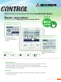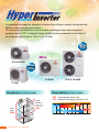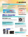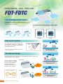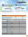
1
R410A
High Performance Air-Conditioning
Back
Light
Back
Light
FD
series
I nv e r t e r P a ck a g e d A i r C o n d i t i o n e r s
Simple
setting by
tapping
button
only
Run / Stop
High power operation
Energy-saving operation
Maximum capacity
operation (Max 15 minutes)
• Increased compressor speed
• Increased air flow
• Changes set temperature at 28ºC in
cooling mode and 22ºC in heating mode,
25ºC in auto mode.
• Operation correction by outdoor
temperature
Main functions
Energy management
Peak cut timer • Automatic temperature set back • Weekly timer • Set ON/OFF timer by hour
• Set ON/OFF timer by clock • Fan only operation • Sleep timer
Comfort
Individual flap control • High power operation • External ventilation ON/OFF • Warm up operation
Automatic fan speed • Temperature increment setting by 0.5ºC
2
High Performance Ai r C o n d it io n in g
Advanced touch screen panel with full dot Liquid Crystal Display
Basic operation
All settings done by tapping touch screen panel
Operation mode setting screen
Setting temperature screen
The operation mode can
be selected by simply tapping
this button.
You can select the desired
temperature by tapping the ▲▼
button.
Operation mode
Cooling
Dry
Auto
Fan
Heating
Convenience
LCD contrast setting • Back light setting • Filter clean sign • Control sound • Outdoor silent mode
• Summer time setting • Home leave mode • Indoor & outdoor temperature display
• Heating standby display • Defrosting operation display • Auto cooling/heating display • ºC/ºF display
• Administrator settings • Room name setting
Service
Error code display • Operation data display • Next service data display • Contact company display
• USB connection (mini-B)
P a ck a ge d A i r C o n di ti oners
3
Our advanced technology has allowed us to achieve high efficiency, powerful heating and long
distance refrigerant piping specifications.
This feature permits installation of the units when a heating operation under temperature
conditions down to -20˚C is required. Design flexibility has been improved by an extension of
the refrigerant piping length to 100m (12.5 & 14.0kW).
Blue
Fin
Micro
5.0 & 6.0kW
Blue
Fin
10.0kW
12.5 & 14.0kW
7.1kW
Long piping (in case of 12.5 & 14.0kW)
Height
difference
(Outdoor higher
than Indoor)
Piping
length
100m
4
High Performance Ai r C o n d it io n in g
Strong heating (in case of 7.1~14.0kW)
-20C
-15C
: Heating operation down to -20C
: Nominal heating capacity maintained at -15C
Heating
-20C
30m
Cooling
-15C
-30
-20
+20C
-10
0
10
20
+43C
30
40
50
Powerful heating capacity
Maximum heating capacity has been increased by optimising
refrigeration control, the use of electronic expansion valves and our
twin rotary compressors.
The Hyper Inverter series can reach the set temperature very quickly.
Normal heating capacity can be maintained when the outdoor
temperature is -15°C. It is very effective for use in cold areas.
Heating capacity (in case of 12.5kW)
(kW)
18.0
Keeping nominal heating
capacity at -15C
14.5
14.0
Hyper Inverter
40C
nominal
heating
capacity
14.0kW
-15C
2C
Heating capacity
50C
Hyper Inverter
30C
Micro Inverter
8.8
0
Temperature of supply air can reach 40C
in 4 minutes after start up under low
temperature operation conditions (at both
indoor and outdoor temperature of 2C)
and can reach 50C in 8 minutes after that.
20C
7C
10C
Micro Inverter
0C
Micro Inverter
4minutes
8minutes
Compact design of outdoor units
FDC100VN 10.0kW
Our single fan micro 10.0kW condenser is one of the most
compact in the industry being only 845(h)x970(w)x370(d)
Size reduction and high efficiency
performance of the DC twin rotary
compressor
Reduction in height by 22.3%
Reduction in volume by 44.1%
Height at 342mm
Height at 440 mm
The DC twin rotary compressor can operate at speeds as high as 120 rps
to achieve the required capacity. Vector control provides perfect
compressor control. Starting current has reduced significantly and
vibration has been minimized.
Outside diameter of shell
ø185mm
ø133mm
Former
compressor
New model
DC rotary compressor
Improved efficiency of the
heat exchanger
Re-designing the fins to a straight shape has reduced the pressure
loss of the air flow in the heat exchanger. A new surface treatment on
the fins has enhanced the frost resistance capacity compared to
former models. A high speed fan motor has increased the airflow
which allows cooling capacity to be maintained even at high outdoor
air temperatures.
* Vector control:
To convert the current
wave to a smooth
sinusoidal waveform.
Former model
Current model
Protection
Improved operation of the electronic expansion valve allows for
more reliable oil return and this assists to protect the
compressor.
P a ck a ge d A i r C o n di ti oners
5
Ceiling Cassette - 4way - Indoor units
FDT.FDTC
Individual flap control system
Individual flap control is available even after
installation. This means that the installation area has
become wider than before.
The outlet design has been perfected to allow sufficient
air flow that can reach a long distance from the indoor
unit.
Previous
Current
Flap control system
The design of the heat exchanger has
changed from 2 parts to a single piece.
The height of the indoor unit has been
reduced significantly.
is not applicable to the Individual flap control system
*RCH-E3
and the Flap control system.
Upper
position
Movable
range
Lower
position
For person who is far
from the indoor unit
The thinnest design
The design of the heat exchanger has changed from 2 parts to 1 part, the
height of indoor unit is reduced.
DC fan motors are used to
increase efficiency. Weight
has been reduced and as
a result the unit has
become one of the most
compact in the industry.
Shape of heat exchanger
Previous
Current
FDT125~140
365mm
298
FDT71
270mm
mm
High Performance Ai r C o n d it io n in g
reduction!!
mm
246
6
18%
For both persons who are
feeling hot or cold
9%
reduction!!
Can cool both the kitchen
and the guests
Duct Connected - Middle Static pressure
FDUM
Automatic external static pressure (E.S.P.) control
By using a DC motor, the optimum air flow volume
can be achieved by this automatic control.
New
FDUM
Duct
Duct
The indoor unit will recognize external static
pressure automatically and keep rated air flow
volume.
Longer Duct
Ceiling
Keep the same
air flow volume
Setting No.
No.1
No.2
No.3
No.4
No.5
No.6
No.7
No.8
No.9
E.S.P.
10Pa
20Pa
30Pa
40Pa
50Pa
60Pa
70Pa
80Pa
90Pa 100Pa
No.10
E.S.P. button
External static pressure can be
set by E.S.P. button.
Improved servicing
Fan unit (impeller and motor) can be pulled out
from the right side of the unit. Maintenance is
available from the right side or from beneath.
Pipe
Fan unit
Unit
Maintenance
hole
Service
space
Improvement of low tap noise dB(A)
Air flow sound has been reduced by a new fan and casing design.
Refrigerant flow sound was been decreased by advanced refrigerant distributor design.
FDUM50VF
FDUM60VF
FDUM71VF
FDUM100VF
FDUM125VF
FDUM140VF
5.0kW
6.0kW
7.1kW
10.0kW
12.5kW
14.0kW
NEW FDUM
26
25
25
30
30
30
Current FDUM
28
28
29
32
33
33
Improvement
-2
-3
-4
-2
-3
-3
Indoor model name
Nominal cooling capacity
P a ck a ge d A i r C o n di ti oners
7
INDOOR UNIT
FDT
CEILING CASSETTE -4way-
FDT 60/125/140VD
FDT 71/100VF
Remote control (Option)
Wired
RC-EX1A
RC-E5
Wireless
Outline drawing (Unit:mm)
Model FDT 60,71VD
8
High Performance Ai r C o n d it io n in g
Model 100,125,140VD
RCH-E3
RCN-T-36W-E
Point
1 Installation
Point
2 Infrared control option
For wireless control simply
insert the infrared receiver
kit on the corner.
Detachable covers at each corner allows
for easy alignment and balance.
The panel does not need to be removed.
Installation time is reduced.
wireless remote control
RCN-T-36W-E
Point
Point
3 Easy checking of drain pan
4 700mm Drain Pump
To check the drain pan
simply remove the corner
lid.
Drain can be discharged
upwards by 700mm from the
ceiling surface. The 260mm
flexible hose is supplied as
standard equipment.
Flexible hose
less than
700mm
FDT Series
Indoor
Outdoor
Power supply
FDT100VNVF
FDT125VNXVD
FDT140VNXVD
FDT60VD
FDT71VF
FDT100VF
FDT125VD
FDT140VD
SRC60ZJX-S
FDC71VNX
FDC100VN
FDC125VNX
FDC140VNX
5.6 (2.8-6.3)
7.1 (3.2-8.0)
10.0 (4.0-11.2)
12.5 (5.0-14.0)
14.0 (5.0-16.0)
6.7 (3.1-7.1)
8.0 (3.6-9.0)
11.2 (4.0-12.5)
14.0 (4.0-17.0)
16.0 (4.0-18.0)
N/A
7.2
N/A
15.6
16
1.52
2.04
2.76
3.28
4.19
1.70
1.94
2.74
3.43
4.2
1 Phase 230V 50Hz
Heating H1
kW
Heating H2
Input
FDT71VNXVF
Indoor Unit
Cooling T1
Capacity
FDT60ZJXVD
Cooling T1
Heating H1
kW
EER
Cooling T1
3.68
3.48
3.62
3.81
3.34
COP
Heating H1
3.94
4.12
4.08
4.08
3.81
Sound pressure level
(JIS C9612)
Indoor
P-Hi:46 Hi:33
Me:31 Lo:30
P-Hi:46 Hi:35
Me:33 Lo:31
P-Hi:51 Hi:40
Me:37 Lo:35
P-Hi:51 Hi:42
Me:40 Lo:37
P-Hi:51 Hi:43
Me:41 Lo:38
54
51
49
50
52
dB(A)
64
66
70
70
72
l/s
P-Hi: 466 Hi: 300
Me: 266 Lo: 233
P-Hi: 466 Hi: 350
Me: 316 Lo: 283
P-Hi: 616 Hi: 450
Me: 400 Lo: 333
P-Hi: 616 Hi: 500
Me: 450 Lo: 383
P-Hi: 616 Hi: 500
Me: 450 Lo: 383
mm
T-PSA-3AW-E
(35 x 950 x 950)
Outdoor
Sound power level (JIS
C9612)
Outdoor
Airflow
Indoor
Panel
External dimensions
(HXWXD)
Net weight
Indoor
Outdoor
Indoor
Outdoor
Liquid line
Refrigerant piping
dB (A)
Gas line
mm
kg
mm
T-PSA-3BW-E
(35 x 950 x 950)
246 x 840 x 840
640 x 800(+71) x 290
298 x 840 x 840
750 x 880(+88) x 340
845 x 970 x 370
Unit 27 Panel 5.5
60
81
Ø9.52
Ø12.7
Ø15.88
Flare connection
kg
1.5
Pre charged to pipe length
m
15
m
30
Controller
105
Ø6.35
Quantity
Maxium Pipe Length
1300 x 970 x 370
Unit 24 Panel 5.5
45
Connection method
Refrigerant R410A
T-PSA-3AW-E
(35 x 950 x 950)
2.95
3.8
4.5
30
50
100
RC-E5, RC-EX1 or RCN-T-36W-E
VF model may be supplied in lieu.
P a ck
di ti oners
c kaa ge d A i r C o nndi
9
INDOOR UNIT
FDTC
CEILING CASSETTE
-4way Compact (600 X 600mm)-
Fits into standard
600 x 600 ceiling
FDTC50VF
Remote control (Option)
Wireless
Wired
RC-EX1A
Point
RCH-E3
2 Quiet operation
(Sound Pressure level in the Lo mode)
OA Spacer TC-OAS-E (option)
Joint Duct TC-OAD-E (option)
(dB)
36
Utilizing OA spacer which comes
as optional equipment, outside air
can be taken into inside.
35
3dB
Down
35dB
34
Indoor Unit FDTC
32dB
33
32
30dB
31
300mm
OA
Spacer
30
29
28
Ceiling OA
surface
27
OA
Panel
RCN-TC-24W-ER
Point
1 Taking OA (Outside air) into inside
Using 1 joint duct:
OA comes up to 1.3m3/min.
Using 2 joint ducts:
OA comes from 1.3 to
2.6m3/min.
RC-E5
5dB
Down
26
Joint Duct
25
Previous
(Cooling/Heating)
Point
3 “CLEARER”Air Flow
New
(Cooling)
New
(Heating)
Point
5 Compact and Convenient
• 600mm Drain Pump
New shape & angled louver redirects the
air current away from the ceiling, to reduce
ceiling stains
Point
4 Installation Workability
For wireless control simply insert the
infrared receiver kit on a corner of the
panel
wireless
remote control
RCN-TC-24W-ER
10
High Performance Ai r C o n d it io n in g
Drain can be discharged upward by 600 mm from the ceiling
surface close to the indoor unit.
It allows a piping layout with a high degree of freedom
depending on the installation location.
• 600 x 600 ceiling
Indoor unit size (W:570 x D:570) brings easy installation for
600 x 600 ceiling and Panel size (700 x 700) is suitable for
600 x 600 ceiling. Height is one of the industry's lowest level
at 248mm and weight is 16.5kg only.
Flexible hose
600mm
248mm
Outline drawing (Unit:mm)
FDTC Series
FDTC50ZJXVD
Indoor
FDTC50VD
Outdoor
Power supply
SRC50ZJX-S
Outdoor Unit
1 Phase 230V 50Hz
Cooling T1
Capacity
Heating H1
5.0(1.1-5.6)
kW
Heating H2
Input
Cooling T1
Heating H1
EER
Cooling T1
COP
Heating H1
Sound pressure level (JIS C9612)
Indoor
Outdoor
Sound power level (JIS C9612)
Outdoor
Airflow
Panel
External dimensions (HXWXD)
Net weight
5.10
kW
Maxium Pipe Length
Controller
1.45
3.20
3.72
dB (A)
P-Hi:47 Hi:42 Me:36 Lo:30
54
63
Indoor
l/s
P-Hi: 225 Hi: 191 Me: 150 Lo: 133
TC-PSA-25W-E
mm
Indoor
Outdoor
Indoor
Outdoor
Gas line
mm
kg
mm
Connection method
Refrigerant R410A
1.56
dB(A)
Liquid line
Refrigerant piping
5.4 (0.6-6.3)
35 x 700 x 700
248 x 570 x 570
640 x 800(+71) x 290
Unit 15 Panel 3.5
45
Ø6.35
Ø12.7
Flare connection
Quantity
kg
1.5
Pre charged to pipe length
m
15
m
30
RC-E5, RC-EX1 or RCN-TC-24W-ER
VF model may be supplied in lieu.
P a ck
c kaa ge d A i r C o nndi
di ti oners
11
INDOOR UNIT
FDU
LIMITED
STOCK
DUCT CONNECTED
-High Static pressure-
FDU 100/125/140VD
Wired
remote control
RC-E5 RCH-E3
(Option)
Outline drawing (Unit:mm)
FDU100,125,140VD
1412
High Performance Ai r C o n d it io n in g
(Option)
Wireless
remote control
RCN-KIT3-E
(Option)
Point
1 Installation features
Quiet, Lightweight and Compact
A drain pump is fitted to all units as standard and can can be used in the event that gravity drainage is not possible. Remote
sensors are recommended to be used with series to ensure optimum operation.
Height
350mm
600mm
FDU Series
Indoor
Outdoor
Power supply
FDU140VNXVD
FDU100VD
FDU125VD
FDU140VD
FDC125VNX
FDC140VNX
FDC100VN*
1 Phase 230V 50Hz
Heating H1
kW
Heating H2
Input
FDU125VNXVD
Outdoor Unit
Cooling T1
Capacity
FDU100VNVD
Cooling T1
Heating H1
kW
10.0 (4.0-11.2)
12.5 (5.0-14.0)
14.0 (5.0-16.0)
11.2 (4.0-12.5)
14.0 (4.0-17.0)
16.0 (4.0 -18.0)
8.5
14.3
14.4
2.88
3.44
4.20
2.99
3.67
4.30
EER
Cooling T1
3.47
3.63
3.33
COP
Heating H1
3.74
3.81
3.72
Hi:42 Lo:37
Hi: 43 Lo: 38
Hi: 43 Lo: 38
Sound pressure level (JIS C9612)
Indoor
Outdoor
dB (A)
49
50
52
70
72
Outdoor
Airflow
Indoor
l/s
Hi:566 Lo:450
Hi: 700 Lo:558
External Static Pressure
Indoor
Pa
60/130@566 l/s
60/130@700 l/s
External dimensions (HXWXD)
Net weight
Indoor
Outdoor
Indoor
Outdoor
Liquid line
Refrigerant piping
Gas line
dB(A)
70
Sound power level (JIS C9612)
mm
kg
350 x 1370 x 650
845 x 970 x 370
63
81
Ø15.88
Return % Supply Air Connection
Controller
Flare Connection
Quantity
kg
Pre charged to pipe length
m
Maxium Pipe Length
m
Flange
105
Ø9.52
mm
Connection method
Refrigerant R410A
1300 x 970 x 370
mm
3.8
4.5
30
50
100
290 x 1368
RC-E5, RC-EX1 or RCN-KIT3-E
P a ck a ge d A i r C o n di ti oners
13
INDOOR UNIT
FDUM
DUCT CONNECTED
-Middle Static pressure-
Remote control (Option)
Wired
RC-EX1A
RC-E5 RCH-E3
Outline drawing(Unit:mm)
Model FDUM50VF
FDUM 50/60/71/100/125/140VF
Point
1 Thin design
The height of all FDUM models is only 280mm.
70mm less
19mm less
H 350
H 299
H 280
H 280
FDUM100/125/140VF
FDUM50/60/71VF
Models FDUM60,71VF
Note: FDUM71VF is not supplied with circular spiggots.
14
High Performance Ai r C o n d it io n in g
Models FDUM100,125,140VF
Wireless
RCN-KIT3-E
2 600mm Drain Pump
Point
Drain can be discharged upwards by 600mm from the ceiling
surface. It allows a piping layout with a high degree of freedom
depending on the installation location.
Flexible hose
less than
600mm
FDUM Series
Indoor
Outdoor
Power supply
Heating H1
Cooling T1
Heating H1
EER
Cooling T1
COP
Heating H1
Sound pressure level
(JIS C9612)
Sound power level
(JIS C9612)
Airflow
Indoor
kW
Net weight
Outdoor
Indoor
dB (A)
FDUM100VNVF
FDUM125VNXVF
FDUM140VNXVF
FDUM50VF
FDUM60VF
FDUM71VF
FDUM100VF
FDUM125VF
FDUM140VF
SRC50ZJX-S
SRC60ZJX-S
FDC71VNX
FDC100VN
FDC125VNX
FDC140VNX
Outdoor
Indoor
Outdoor
Gas line
5.0 (2.2-5.6)
5.6 (2.8-6.3)
7.1 (3.2-8.0)
10.0 (4.0-11.2)
12.5 (5.0-14.0)
14.0 (5.0-14.5)
5.4 (0.6-6.3)
6.7 (0.6-7.1)
8.0 (3.6-9.0)
11.2 (4.0-12.5)
14.0 (4.0-17.0)
16.0 (4.0-18.0)
4.2
4.8
6.9
N/A
5.2
5.2
1.56
1.75
2.20
2.92
3.60
4.40
1.70
2.00
2.20
3.20
3.90
4.54
3.21
3.20
3.23
3.42
3.47
3.18
3.18
3.35
3.64
3.50
3.59
3.52
P-Hi:37 Hi:32
Me:29 Lo:26
P-Hi:36 Hi:31
Me:28 Lo:25
P-Hi:38 Hi:33
Me:29 Lo:25
P-Hi:44 Hi:38
Me:36 Lo:30
P-Hi:45 Hi:40
Me:34 Lo:29
P-Hi:47 Hi:40
Me:35 Lo:30
50
54
60
49
50
49
dB(A)
63
64
66
70
70
72
l/s
P-Hi: 217 Hi: 167
Me: 150 Lo: 133
P-Hi:333 Hi:250
Me:217 Lo:167
P-Hi: 400 Hi: 316
Me: 250 Lo: 166
P-Hi:600 Hi:467
Me:417 Lo:317
P-Hi:650 Hi:533
Me:433 Lo:333
P-Hi:800 Hi:583
Me:467 Lo:367
Pa
100@217 l/s
100@333 l/s
100@400 l/s
100@600 l/s
100@650 l/s
100@800 l/s
280 x 750 x 635
280 x 950 x 635
280 x 950 x 635
280 x 1370 x 740
280 x 1370 x 740
280 x 1370 x 740
640 x 800(+71)
x 290
640 x 800(+71)
x 290
750 x 880(+88)
x 340
840 x 970 x 370
1300 x 970 x 370
1300 x 970 x 370
29
34
34
54
54
54
45
45
60
81
105
105
Ø6.35
Ø6.35
Ø9.52
Ø9.52
Ø9.52
Ø9.52
Ø12.7
Ø12.7
Ø15.88
Ø15.88
Ø15.88
Ø15.88
Indoor
Liquid line
Refrigerant piping
kW
Outdoor
External Static Pressure
External dimensions
(HXWXD)
FDUM71VNXVF
1 Phase 230V 50Hz
Heating H2
Input
FDUM60ZJXVF
Outdoor Unit
Cooling T1
Capacity
FDUM50ZJXVF
mm
kg
mm
Connection method
Flare Connection
Quantity
kg
1.5
1.5
2.95
3.8
4.5
4.5
Pre charged to
pipe length
m
15
15
30
30
30
30
Maxium Pipe Length
m
30
30
50
50
100
100
Supply Air Connection
mm
170 x 680
170 x 880
170 x 880
170 x 1200
170 x 1200
170 x 1200
Return Air Connection
mm
200 x 660
200 x 860
200 x 860
235 x 1280
235 x 1280
235 x 1280
Refrigerant R410A
Controller
RC-E5, RC-EX1 or RCN-KIT3-E
P a ck a ge d A i r C o n di ti oners
15
INDOOR UNIT
FDEN
CEILING SUSPENDED
FDEN 100/125VF
Remote control (Option)
Wireless
Wired
RC-EX1A
RC-E5
RCH-E3 RCN-E1R
Outline drawing (Unit:mm)
a (Suspension bolts pitch)
b
52
68
Liquid piping
Gas piping
e
d
173
5
135
40
Space for installation and service
Holes for suspension bolts
(M8 to M10x4pcs.Not included)
410
145
290(Suspension bolts pitch)
24
100
or more
40
Air outlet
53
109
c
690
195
235
300 or more
24
150
or more
5
or more
Obstacles
Drain hole
connection(1)
(VP20 (I.D.20))
271
Air inlet grille
Gas piping
Drain hole
connection(1)
(VP20(I.D.20))
75 Liquid piping
110
135
Dimension Table
model
FDEN100~125
16
High Performance Ai r C o n d it io n in g
53
10
Drain hole
connection(1)
(VP20(I.D.20))
76
Note(1) The slope of drain piping
inside the unit is able
to take incline of 10mm.
308
Indication board
a
b
c
d
e
1572
1540
1620
255
250
Point
1 Improved installation workability
Point
2 Compact and modern design
Increased freedom of a piping layout
Up
Height
250mm
Right
Rear
The refrigerant pipe from the unit can be arranged in three directions,
rear, right and up. The drain pipe can be arranged in two directions,
left and right. This will allow a free layout of piping for various
installation conditions. The unit can only be serviced from below.
All models fit compactly on ceiling. (Height-210mm or 250mm).
Plain, modern design featuring rounded edges gives room a
comfortable atmosphere.
FDEN Series
FDEN100VNVD
FDEN125VNXVD
Indoor
FDEN100VD
FDEN125VD
Outdoor
FDC100VN
FDC125VNX
Power supply
Outdoor Unit
1 Phase 230V 50Hz
Cooling T1
Capacity
Input
Heating H1
kW
10 (4.0-11.2)
12.5 (5.0-14.0)
11.2 (4.0-12.5)
14.0 (4.0-17.0)
Heating H2
8.7
15.0
Cooling T1
2.85
3.86
kW
2.97
3.77
EER
Cooling T1
3.51
3.23
COP
Heating H1
3.77
3.71
Cooling T1
2
1
Energy Label
Sound pressure level (JIS C9612)
Heating H1
Heating H1
Indoor
Outdoor
Sound power level (JIS C9612)
Outdoor
Airflow
Indoor
External dimensions (HXWXD)
Net weight
Indoor
Outdoor
Indoor
Outdoor
Liquid line
Refrigerant piping
Gas line
Stars
dB (A)
2.5
2
P-Hi:46 Hi:44 Me:41 Lo:39
P-Hi:50 Hi:46 Me:44 Lo:43
49
50
dB(A)
70
70
l/s
P-Hi:466 Hi:433 Me:383 Lo:350
P-Hi:533 Hi:483 Me:433 Lo:383
mm
kg
250 x 1620 x 690
845 x 970 x 370
49
81
Ø15.88
Flare Connection
Quantity
kg
Pre charged to pipe length
m
Maxium Pipe Length
Controller
105
Ø9.52
mm
Connection method
Refrigerant R410A
1300 x 970 x 370
m
3.8
4.5
30
50
100
RC-E5, RC-EX1 or RCN-E-E
VF model may be supplied in lieu.
c kaa ge d A i r C o nndi
P a ck
di ti oners
17
OUTDOOR UNIT 5.0-14.0kW
Micro
SRC50ZJX-S
SRC60ZJX-S
FDC71VNX
FDC100VN
FDC125VNX
FDC140VNX
Blue Fin 7.1-14.0kW
Due to application of blue coated fins
(KS101) for the heat exchanger of the new
outdoor unit, corrosion resistance has been
improved compared to previous models.
Base heater kit (option)
This kit is recommended to be used
in an area where the temperature
drops below 0˚C.
Blue
Fin
CW-H-E
applied for
FDC100VN
FDC125~140VNX
Installation workability
Enhanced installation workability thanks to the extended pipe length – one of the longest
levels in the industry. Units are pre-charged with refrigerant.
Point
1 Piping length – 100m (Hyper Inverter 12.5~14.0kW)
Micro Inverter
Height difference
Height difference
(Outdoor higher than Indoor)
(Outdoor higher than Indoor)
Piping
length
Piping
length
Piping
length
Height
difference
5~6
30m
20m
7.1
50m
30m
12.5~14
100m
30m
kW
kW
10
Piping
length
Height
difference
50m
30m
Point
2 Refrigerant precharged piping length extending to 30m
Refrigerant precharged piping length extends up to 30m. (5.0 & 6.0kW up to 15m)
This eliminates the need to add refrigerant on site, which sets it free from the trouble of excessive or insufficient charging of refrigerant, and
allows carrying out the installation smoothly.
18
High Performance Ai r C o n d it io n in g
High efficiency
Reduction of air flow pressure loss
Increase of heat transfer efficiency
Pressure caused by air flow in the indoor unit
is reduced by making the air outlet larger. The
reduction of pressure reduces the load on the
fan motor so efficiency increases.
Heat transfer efficiency has improved by using high
efficiency piping and by the redesign of the heat
exchanger from 2 to 1 piece.
Convenience
CnT terminal
XR2
XR3
XR4
XR5
output1 (run)
output2 (heat)
output3 (comp on)
output4 (alarm)
in put
Power
source
CnT
A dry contact is fitted to each indoor
unit which is used when a signal
output is required.
common
XR1
XR2
XR3
XR4
XR1
XR5
XR1~5 : approx. DC12v
Monitoring Function
Condensers are fitted with RS232C so you can
connect directly to your PC for monitoring.
MHI service software, Mente PC makes service
tasks simple.
Remote control RC-E5
The new remote control for all indoor units.
Non-polar 2 core wiring is used. Installation is easier.
Previous
3-core
Current
2-core
All models employ R410A with RoHS* directive
Employment of lead free solder
Adapt to RoHS
In order to comply with RoHS standard, the new inverter
series use lead free solder.
Employment of
refrigerant
All models of the FD inverter series use
refrigerant R410A characterized by the ozone
depletion coefficient being 0.
*"RoHS" is the abbreviation of the new European standard, which means
Restriction of Hazardous Substances.
P a ck a ge d A i r C o n di ti oners
19
Control System
SUPERLINK-
KX6 series
SC-SL1N-E
RAC series
(SRK/SRF-ZJX-S)
SC-BIKN-E
SC-ADNA-E
SC-SL2NA-E
SC-ADNA-E
SC-ADNA-E
Central Control
SC-SL1N-E
Start/stop control of up to 16 indoor units is
possible either individually or collectively. With
simple operations, you can effect centralised
control.
PC windows central control
SC-WGWNA-A/B
(SC-WGWNA-B has electric power calculation function)
SC-SL2NA-E
SC-SL3N-AE/BE
Centralised control of up to 64 indoor units. It
can allow connection with a weekly timer
without using any interface.
BMS interface unit
SC-BGWN-A/B
Additional engineering service cost is required.
Please consult your dealer when using this central
control.
3820
High Performance Ai r C o n d it io n in g
SC-LGWN-A
(BACnet gateway)
(LonWorks gateway)
Up to 96 cells (some cells can have two or
more indoor units and total number of indoor
units can be up to 128 units) are controlled
centrally from a BMS.
Up to 96 indoor units (48 indoor unit x 2) are
linked as an open network. Centrally
controlled through LonWorks.
(SC-WGWN-B has electric power calculation function)
Up to 96 cells (some cells can have two or
more indoor units and total number of
indoor units can be up to 128 units) are
controlled from the Internet.
Easy operation through the large color LCD
and touch panel. Up to 128 indoor units can be
controlled, when three SUPERLINK-II systems
are connected.
Additional engineering service cost is required. In case
of SC-BGWN-B, communication test by qualified
person regarding electric cost calculation function is
required before commissioning. Please consult your
dealer when using this gateway.
Additional engineering service cost is required.
Please consult your dealer when using this gateway.
SUPERLINK E BOARD (SC-ADNA-E)
This board is used when conducting control of the single package (wired remote control unit) 1-type series using a
network option (SC-SL1N-E, SC-SL2NA-E, etc).
(1) Functions
(a) Transmits the settings from the network option to the indoor units.
(b) Returns the priority indoor unit data in response to a data request from the network option.
(c) Inspects the error status of connected indoor units and transmits the inspection codes to the network option.
(d) A maximum of 16 units can be controlled (if in the same operation mode).
(2) Wiring connection diagram
Blue
A
Run
Abnormal
SL E board
A
Blue
B
B
LED3
LED2
Black
X
X
White
Y
Y
ON
SW3
OFF
SW2
SW1
Connected to the terminals for
Superlink signal lines
MVVS 0.75 - 1.25mm2
Connected to the remote controller terminals (no
polarity) (the length should be 600 m or shorter)
200 m or shorter
0.5 mm2 x 2 cores
300 m or shorter
0.75 mm2 x 2 cores
400 m or shorter
1.25 mm2 x 2 cores
600 m or shorter
2.0 mm2 x 2 cores
Network address setting switches
[000]-(127)
Master/Sub
address
Basic Connections
Plural Controls by Multiple Remote Controls. Mixture of Multiple Units
Outdoor unit
Outdoor unit
Internal/external Crossing
Internal/external Crossing
Indoor unit
X Y
SL E Board
X Y
A B
Inside Inside Inside Inside
Remote control
X Y
SL E
Board
Network
options
Network A B
options
R
R
• Transmit the information of plural “Master” units to the network.
• Transmit the abnormalities of the “Slave” units to the network.
Setting the plural “Master/Slave” units with the dip SW of the printed circuit board.
Setting the “Master/Slave” remote controls with the dip SW of the remote control board.
Plural Controls by Multiple Remote Controls. Mixture of Multiple Units
Outdoor unit
Outdoor unit
Internal/external Crossing
SL E
Board
R
Inside Inside Inside
SL E
Board
R
Network
options
Outdoor unit
Internal/external Crossing
Inside Inside Inside Inside
Without Remote Control
R
R
Set up “000” to “127” using address switch on the SL E board.
Internal/external Crossing
Inside Inside
SL E
Board
Network
options
Set the SL E board dip SW
to “Master” SW3-1 ON.
The network option
SLA-1-E, SL1N-E is not
allowed (This will disturb
switching of the operation
mode)
Wireless Kit
Outdoor unit
Internal/external Crossing
Inside Inside
SL E
Board
Network
options
Wireless Kit
Wireless
remote control
(3) Metal box dimension
85
35
30
70
90
5
22.5
100
40
2-ø6
P a ck a ge d A i r C o n di ti oners
2139
Control Systems - Individual Control
Remote Control line up
indoor unit
wired
remote control
RC-E5
all models
RCH-E3
wireless
indoor unit
FDT
FDTC
FDUM, FDU
FDEN
remote control
RCN-T-36W-E
RCN-TC-24W-ER
RCN-KIT3-E
RCN-E-E
Wired remote control with weekly timer (option)
RC-E5
Run hour metres to facilitate maintenance checking
RC-E5 stores operation data when an anomaly occurs and indicates the error on
the LCD. It also displays cumulative operation hours of the air conditioner and
compressor since commissioning.
The RC-E5 controller enables
extensive access to service
and maintenance technical
data combined with easy to
use functions and a clear
LCD display.
Weekly timer function as standard
RC-E5 provides (as a standard feature) a weekly timer, which allows
one-week operation schedules to be registered. A user can specify up to
four times a day to start/stop the air conditioner. (Temperature setting is also
possible with the timer).
Timer operation
Room temperature controlled
by the remote control sensor
The temperature sensor is housed in the top
section of the remote control unit. This
arrangement has improved the sensitivity of the
remote control unit’s sensor, which permits more
finely controlled air conditioning.
Changeable set temperature ranges
RC-E5 allows the upper and lower limits of a set temperature range to be
specified separately.
By adjusting a set temperature range, you can ensure energy saving air
conditioning by avoiding excessive cooling or heating.
Changeable range
Upper limit
20~30C(effective for heating operation)
Lower limit
18~26C(effective for non-heating operation)
Simple remote control (option)
RCH-E3 (wired)
Considering specialised usage in hotel rooms,
control buttons are limited only to minimum
required functions such as ON/OFF, mode,
temperature setting and fan speed. It is really
simple and easy to use.
RCH-E3 is not applicable to the Individual flap control
system and the Flap control system.
When RCH-E3 is used, the fan has 3 speed settings
(Hi-Me-Lo) only.
Up to 16 units
It can control up to 16 units individually, by pressing the AIR CON No. button.
AUTO restart
This function allows starting the air conditioner automatically when power supply
is restored after power failure or by turning on the power switch.
Wireless remote control (option)
Thermistor (option)
SC-THB-E3
For wireless control simply insert the infrared
receiver kit on a corner of the panel.
RCN-T-36W-E,
RCN-TC-24W-ER
RCN-KIT3-E
When wireless remote control is used, the fan has 3 speed settings (Hi-Me-Lo) only.
22
High Performance Ai r C o n d it io n in g
RCN-E-E
This sensor is used when individual remote control is
not required in each room and the system is under
central control. By installing sensors in strategic
locations through out the structure greater comfort
control is achieved. In many instances one additional
sensor is all that is required.
What is a Heat Pump ?
What is hot water supply by Heat
Pump technology system ?
Heat energy is absorbed from the outside air when it
passes through the outdoor unit; the energy is transported
to the indoor unit in the refrigerant [in this case CO 2] within
the piping system. This eliminates the need to bore holes or
Increasing refrigerant temperature through
compressing process by compressor
bury coils of pipes in the ground as used in conventional
ground source systems.
Air
Hot water
CO2 refrigerant
Air source heat
Overwhelming high capacity and high efficiency
heat transfer
Commercial use Heat Pump Water Heater
low
temperature
heat
high
temperature
Decreasing refrigerant temperature through
expanding process by expansion valve
Re
High Performance
-25°C 90°C
Natural refrigerant CO Air to Water System
30kW~480kW (for commercial use)
cov
e
ri ng
h
e at of th
e ai r
2
-7°C
under extreme low hot water supply
outdoor temperature
for kitchen
100%
down to
-7°C
can keep 100%
capacity
big restaurant
1,000
Overwhelming high capacity and high efficiency
for bathroom
senior care home/hospital
wedding venue
5,000
resort hotel
10,000
15,000
(L /day)
What is a Heat Pump ?
Heat energy is absorbed from the outside air when it
passes through the outdoor unit; the energy is transported
to the indoor unit in the refrigerant [in this case CO 2] within
the piping system. This eliminates the need to bore holes or
bury coils of pipes in the ground as used in conventional
Supply center
of meals
Spa/company dormitory/
recreation facility
Air
Ecology
-7°C
100%
down to
-7°C
COP:
COP = Capacity (kW) /
Power consumption (kW)
can keep 100%
capacity
Easy operation
Advanced touch screen panel with full dot Liquid Crystal display
eco touch REMOTE CONTROL
Hot water
CO2 refrigerant
4.3!
the industry’s top level
The first introduction of 30kW inverter type, Achieving
the industry's top level COP4.3. Keeping high efficiency
and saving energy operation throughout the year.
city hotel/business
hotel
Increasing refrigerant temperature through
compressing process by compressor
Air source heat
heat
school/company
lunch center
What is hot water supply by Heat
Pump technology system ?
ground source systems.
low
temperature
-25°C 90°C
under extreme low hot water supply
outdoor temperature
barber parlor
4.3!
the industry’s top level
The first introduction of 30kW inverter type, Achieving
the industry's top level COP4.3. Keeping high efficiency
and saving energy operation throughout the year.
High Performance
small restaurant
0
Ecology
COP:
COP = Capacity (kW) /
Power consumption (kW)
User friendly
Easy operation
heat transfer
Advanced touch screen panel with full dot Liquid Crystal display
high
temperature
High level of visibility
•LCD panel with light tap operation
introduced as the industry's first
eco touch REMOTE CONTROL
Decreasing refrigerant temperature through
expanding process by expansion valve
•Big LCD with 3.8 inch full dot display
•Back light function
High level of
visibility with only three buttons
•Simple
interface
User friendly
•LCD panel with light tap operation
•Big LCD with 3.8 inch full dot display
introduced as the industry's first
•Back light function
•Simple interface with only three buttons
Re
cov
e
ri ng
h
Y can check transition of hot
You
water storage amount at a glance.
You can check transition of hot
water storage amount at a glance.
e at of th
e ai r
NEW
RC-Q1E
RC-Q1E
Schedule setting
operation to fill up
Schedule setting
for kitchen
small restaurant
operation to fill up
for bathroom
big restaurant
senior care home/hospital
resort hotel
wedding venue
0
1,000
5,000
10,000
15,000
(L /day)
barber parlor
Supply center
of meals
school/company
lunch center
Spa/company dormitory/
recreation facility
city hotel/business
hotel
Module Chiller System
Module chiller MVC
Module Chiller MVC
Water delivery for cooling & heating
Module Chiller & Fan-coil
Air delivery: Module Chiller & AHU, Ducting
RF = No limitation
RModule chiller gets energy
from the outdoor air
as the heat souse
RNo need to use boiler for heating
RWater delivery to the room
from the module chiller
Module chiller F = Head difference
of total floor
Module chiller
RAHU is conditioned connecting
with module chiller
RConditioned OA is possible
to supply through the AHU
Ducting
Suitable for huge space
Suitable for high-rise building
Fan coil unit
Suitable for glass-exterior
façade building
No need to introduce the outdoor air
AHU
Shopping mall, Gymnasium,
Air-port terminal, Arena etc.
Water piping
RefrigerantVR410A
Fan coil unit
Ducting
Water piping
Air-cooled outdoor unit
Specifications & data in this document are current as of January 2012, but subject to change without notice
Specifications & data in this document are current as of January 2012, but subject to change without notice
P a ck a ge d A i r C o n di ti oners
23
Before starting use
Heating performance
Refrigerant leakage
The heating performance values (kW) described in catalog are the values
obtained by operating at an outdoor temperature of 7C and indoor temperature
of 20C as set forth in the ISO Standards. As the heating performance decreases
as the outdoor temperature drops, if the outdoor temperature is too low and the
heating performance is insufficient, use other heating appliances as well.
The refrigerant (R410A) used for Air conditioner is non-toxic and nonflammable
in its original state.
However, in consideration of a state where the refrigerant leaks into the room,
measures against refrigerant leaks must be taken in small rooms where the
tolerable level could be exceeded. Take measures by installing ventilation
devices, etc.
Indication of sound values
The sound values are the values (A scale) measured in a chamber such as an
anechoic chamber following the ISO Standards. In the actual installation state,
the value is normally larger than the values given in the catalog due to the effect
of surrounding noise and echo. Take this into consideration when installing.
Use in snowy areas
Take the following measures when installing the outdoor unit in snowy areas.
Snow prevention
Install a snow-prevention hood so that the snow does not obstruct the air intake
port or enter and freeze in the outdoor unit.
Use in oil atmosphere
Avoid installing this unit in as atmosphere where oil scatters or builds up, such
as in a kitchen or machine factory.
If the oil adheres to the heat exchanger, the heat exchanging performance will
drop, mist may be generated, and the synthetic resin parts may deform and
break.
Use in acidic or alkaline atmosphere
If this unit is used in acidic atmosphere such as hot spring areas having high
level of sulfuric gases or in alkaline atmosphere including ammonia or calcium
chloride, places where the exhaust of the heat exchanger is sucked in, or at
coastal areas where the unit is subject to salt breezes, the outer plate or heat
exchanger, etc., will corrode. Please ask a dealer or specialist when you use an
air conditioner in places differing from a general atmosphere.
Use in places with high ceilings
If the ceiling is high, install a circulator to improve the heat and air flow
distribution when heating.
Snow piling
In areas with heavy snow fall, the piled snow could block the air intake port. In
this case, a frame that is 50cm or higher than the estimated snow fall must be
installed underneath the outdoor unit.
Automatic defrosting device
If the temperature is low, and the humidity is high, frost will stick to the heat
exchanger of the outdoor unit. If use is continued, the heating performance will
drop.
The “Automatic defrosting device” will function to remove this frost.
After heating for approx, three to ten minutes, it will stop, and the frost will be
removed. After defrosting, hot air will be blown again.
Servicing the air-conditioner
After the air-conditioner is used for several seasons, dirt will build up in the
air-conditioner causing the performance to drop. In addition to regular servicing,
we recommend the maintenance contract (charged for) by a specialist.
Safety Precautions
Air-conditioner usage target
Installation
The air-conditioner described in this catalog is a dedicated cooling/heating
device for human use.
Do not use it for special applications such as the storage of foodstuffs, animals
or plants, computer server rooms, precision devices or valuable art, etc.
This could cause the quality of the items to drop, etc.
Do not use this for cooling vehicles or ships. Water leakage or current leaks
could occur.
Always commission the installation to a dealer or specialist. Improper
installation will lead to water leakage, electric shocks and fires.
Make sure that the outdoor unit is stable in installation. Fix the unit to stable
base.
Before use
Always read the “User,s Manual” thoroughly before starting use.
Usage place
Do not install in places where combustible gas could leak or where there are
sparks.
Installation in a place where combustible gas could be generated, flow or
accumulate, or places containing carbon fibers could lead to fires.
Only persons that are qualified and licensed are permitted to install and service products that contain refrigerants in Australia, go to www.arctick.org.
Suitable access for service must be provided in compliance with industry standards and local regulations.
Australia:
New Zealand:
ABN 92 133 980 275
G.S.T. 105-673-620
Phone: 1300 138 007
Fax: 1800 644 329
NSW & Head Office
Victoria
Queensland
Western Australia
Phone: 0800 138 007 Fax: 09 442 5346
Auckland
9C Commercial Road
Kingsgrove NSW 2208
PO Box 318 Kingsgrove
NSW 1480
2/24 Lakeside Drive
Burwood East
VIC 3151
5/26 Flinders Parade
North Lakes
QLD 4509
Unit 3A 2 Mulgul Rd
Malaga WA 6090
PO Box 667 Belmont
WA 6104
Unit 2 100 Bush Road
Albany 0632
PO Box 300552
Albany 0632
www.mhiaa.com.au
www.mhiaa.co.nz
MRE SPARE PARTS
www.mrespareparts.com.au Tel: +61 (0) 2 9600 7444 Fax: +61 (0) 2 9600 8044
ISO9001
ISO14001
BIWAJIMA PLANT
Mitsubishi Heavy Industries, Ltd.
Air-conditioning & Refrigeration Systems Headquarters
Certified ISO 9001
Certificate number : JQA-0709
MITSUBISHI HEAVY INDUSTRIESMAHAJAK AIR CONDITIONERS CO., LTD.
Certified ISO 9001
Certificate Number : 04100 1998 0813
Our Air Conditioning &
Refrigeration Systems
Headquarters has been
assessed and found to
comply with the
requirements of
ISO14001.
ISO 14001
Certificate 04104 1998 0813 E5
BIWAJIMA PLANT
Mitsubishi Heavy Industries, Ltd.
Air-conditioning & Refrigeration Systems Headquarters
Certified ISO 14001
Certificate number : JQA-EM0256
MITSUBISHI HEAVY INDUSTRIESMAHAJAK AIR CONDITIONERS CO.,LTD.
Certificate Number : 04104 1998 0813 E5
Because of our policy of continuous improvement, we reserve the right to make changes in all specifications without notice. E&OE.
MHIAA297_PAC 08 2012
Our Air Conditioning &
Refrigeration Systems
Headquarters is an ISO9001
approved factory for residential
air conditioners and
commercial-use air
conditioners (including heat
pumps).
MHIAA is proudly sponsoring
Monika's Doggie Rescue