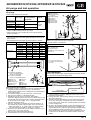
1
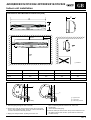
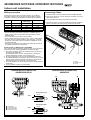
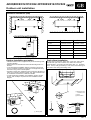
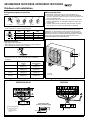
42HQE009/012/018/022
38YE009/012/018/022
INSTALLATION MANUAL
For operation and maintenance instructions of this unit as well as installation
instructions, refer to owner’s manuals.
Contents
Page
General information ....................................................................................
Parts Installation .........................................................................................
Indoor unit installation.................................................................................
Drilling a hole and mounting installation plate ........................................
Connective Pipe and Drainage Installation ............................................
Dimensions and Minimum clearance .....................................................
Wiring connection ...................................................................................
Connecting Cables .................................................................................
Terminal block of indoor unit ...................................................................
Outdoor unit installation ..............................................................................
Minimum clearance.................................................................................
Outdoor installation precaution ..............................................................
Drain elbow installation ...........................................................................
Refrigerant piping connection .................................................................
Wiring connection ...................................................................................
Terminal block of outdoor unit .................................................................
Air purge .....................................................................................................
Test operation .............................................................................................
2
3
4/5
4
4
5
6
6
6
7/8
7
7
7
8
8
8
9
9
ENGLISH
42HQE009/012/018/022-38YE009/012/018/022
Split system “Hi-Wall” indoor and outdoor units
Table I
Indoor unit
Outdoor unit
42HQE009
38YE009
42HQE012
38YE012
42HQE018
38YE018
42HQE022
38YE022
Power Supply
220-240 ~ 50Hz
GB - 1
42HQE009/012/018/022-38YE009/012/018/022
General information
IMPORTANT:
• For correct installation, read this manual before starting
installation.
• Only trained and qualified service personnel should install, repair
or service air conditioning equipment.
Users should not install the air conditioner by themselves.
• All pictures are only sketches. If there is any difference between
pictures in this manual and the actual shape of the air conditioner
you purchased, the actual shape shall prevail.
Unit installation
• Restrictions to connection may be imposed by the supply authority
on the use of equipment if the actual system impedance at the
interface point on the user’s premises exceeds 0.115 ohms for
38YE009, 012, 018 and 0.25 ohms for 38YE022.
• The unit complies with low-voltage (EEC/73/23) and
electromagnetic compatibility (EEC/89/336) directives.
• Carefully recover refrigerant within this unit before final disposal or
when servicing. Never vent refrigerant to atmosphere.
Installation precaution
Installation in the following places may cause trouble.
If it is unavoidable, please, consult with the local dealer.
•
•
•
•
A place full of machine oil.
A saline place such as coast.
A place full of sulfide gas such as hot-spring resort.
Places where there are high frequency machines such as wireless
equipment, welding machine, and medical facility.
• A place of special environmental conditions.
• The appliance shall not be installed in the laundry.
• All of the manufacturing and packageing material used for your new
appliance are compatible with the environment and can be recycled.
• Disconnect the mains power supply switch and wait over 2
minutes without toughing any internal parts of the unit before
servicing the system or handing any internal parts of the unit.
• All field electrical connections are the responsibility of the installer.
• If not using plug, ensure that mains supply connection is made
through a switch that disconnects all poles, with contact gap of a
least 3mm.
• There are some kinds of cord clamp in the accessory parts. If cord
clamp is not used as specified, the power cable and
interconnection wire will be damaged.
Indoor Unit
• The equipment contains R-407C refrigerant, a substance that is
not depleting the ozone layer but must be disposed of in a proper
manner. When disposing of the unit after its operational life,
remove it carefully.
•
•
•
•
• Check that the impedance of the mains power supply is in
conformance with the unit power input indicated in the electric
(EN 61000-3-11).
A place where is no obstacle near the inlet and outlet area.
A place which can bear the weight of the indoor unit.
A place which allows the air filter to be removed.
A place where the reception range is not exposed to direct
sunlight.
• A place where the connective pipe and drain hose is easy to
led out.
• A place 1m or more to TV, radio instrument, in the center of the
room is perfect.
• The indoor unit should be installed 2.3 meters or more above the
floor.
• Control batteries contain polluting elements. When exhausted
they must be disposed of according to local requirements.
• After the installation thoroughly test system operation and explain
all system functions to the owner.
• Leave this manual with the owner for consultation during future
periodic maintenance.
• Use this unit only for factory approved applications:the unit cannot
be used in laundry or steam pressing premises.
Outdoor Unit
• Follow all current national safety code requirements. In particular
ensure that a property sized and connected ground wire is in place.
• A place, which is convenient to installation and not exposed to a
strong wind.
A place that is dry and ventilated.
• A place can bear the weight of the outdoor unit and where the
outdoor unit can be held in the horizontal position.
• A place which does not allow an increase in noise level and
vibration.
• A place where the operation noise and discharge air do not
disturb your neighbor.
• A place free of a leakage of combustible gases.
• An allowable head level at the connective piping is less than
5m and length of the connective piping is up less than 10m.
• No any obstacle which block radiat air.
• Unavailable to children.
• A place which provides the space around the outdoor unit as
required in the diagram of page 3.
• Check that voltage and frequency of the mains power supply are
those required for the unit to be installed;the available power must
be adequate to operate any other possible appliances connected
to the same line.
GB - 2
• The manufacturer declines any liability for damage resulting from
modifications or errors in the electrical or refrigerant connections.
• Failure to observe the installation instructions or use of the unit
under conditions other than those indicated in operating limits ,
will immediately void the unit warranty.
• Failure to observe electric safety codes may cause a fire hazard in
case of short circuits.
• Inspect equipment for damage due to improper transportation or
handing: file an immediate claim with the shipping company.
Do not install or use damaged units.
42HQE009/012/018/022-38YE009/012/018/022
Parts Installation
Part No
ENGLISH
Name of part
Q’ty
Installation plate
Mounting screw A ST3.9x25-C-H
Clip anchor
Mounting screw B ST2.9x10-C-H
Refrigerant pipe
Liquid side
Gas side
Remote controller
Remote controller holder
Seal
Drain elbow
Cable clamp
Ø 6.35
Ø 9.52
Ø 9.52
Ø 12.7
Ø 15.88
Ø 9 (9 ~ 11.5 mm)
(9 ~ 14mm)
018 - 022
1
8
8
2
1
1
1
1
0
1
There are some kinds of cord clamp in the accessory parts, if cord
clamp is not used as specified,the power cable and interconnection
wire will be damaged.
009 - 012,
1
8
8
0
1
1
1
1
1
1
Please install the accessories attached with unit correctly according
to this installation manual.
Note:
1. At least two of A, B, C aspects are free from blocking.
2. When the Outdoor Unit is higher than the Indoor Units, to
prevent the rain from flowing into the indoor along the connection
pipe, a downward tipping arc should be made before the
connection pipe entering the wall to indoor to ensure the lowest
point on the connection pipe is at outdoor.
3. The illustration is for explanation purposes only. The actual
shape of would be slightly different (depend on models).
Cautions on remote controller installation
Before installation, operate the remote controller to determine
its location in a reception range. Keep the remote controller at
least 1m apart from the nearest TV set or stereo equipment.
Do not install the remote controller in a place exposed to direct
sunlight or close to a heating source, such as a stove.
Note that the positive and negative poles are right positions when
loading batteries.
Anchor bolts of out door unit installation
The outdoor unit should not be exposed to strong wind.
Fix the outdoor unit with Ø 10 or Ø 8 anchor bolts.
D
A
B
E
C
12 cm or more
15 cm or more
10 cm or more for 009, 012 e 018
45 cm or more for 022
60 cm or more
100 cm or more
Air blowing direction
Loop the connective cable
Air inlet
Air outlet
Model
D
E
38YE009
548
276
38YE012
530
290
38YE018
560
335
38YE022
560
335
GB - 3
42HQE009/012/018/022-38YE009/012/018/022
Indoor unit installation
Drilling a hole and mounting installation plate
Installation Plate and Its Dimension (mm)
Connective Pipe and Drainage Installation
Drainage
1. Run the drain hose sloping downward. Do not install the drain
hose as illustrated below.
30
250
20
45
65
70
750
65
2. When connection extension drain hose, insulate the
connecting part of extension drain hose with a shield pipe
42HQE009
Connective pipe
280
815
65
42
50
65
49
42HQE012
906
55
1800
432
432
22
465
465
115
50 58
50 58
115
95 42HQE022
Indoor unit outline
Installation plate
150 mm or more to ceiling
120 mm or more to wall
Left refrigerant pipe hole
.
.. .
. ..
.........................................................................................
. . . ..... . . .... . . .
.......
............
3. Fix the end of the connective pipe.
(Refer to Tightening Connection in REFRIGRANT PIPING
CONNECTION).
108
22
Indoor unit
outline
Connective
pipe
43
65 90
42HQE018
95
50
50
65
Pipe cover
Pipe holder
Left piping
Left back piping
Right back piping
Right piping
1. For the left-hand and right-hand piping, remove the rear plate
bushing from the left side of the rear plate.
Explain to clients that the pipe cover must be kept as it may be
used when relocate the air conditioner to any other place.
2. For the left-hand and rear-left-hand piping, install the piping as
shown. Bend the connective pipe to be laid at 43 mm height
or less from the wall.
50
Do not form
a rise
Do not put
the hose end
into water
Right refrigerant pipe hole
Rear-left pipe hole
Rear-right pipe hole
Hooked part
Pipe hole
1. Fix the installation plate.
1. Install the installation plate horizontally on structural parts in
the wall with the spaces provided around the plate.
2. In case of brick, concrete or similar type walls, make 6 mm Ø, holes
in the wall. Insert clip anchors for appropriate mounting screws.
3. Fix the installation plate on the wall.
CAUTION:
• Connect the indoor unit first then the outdoor unit and bend and
arrange the pipe carefully.
• Do not allow the piping to let out from the back of the indoor
unit.
• Be careful not to let the drain hose slack.
• Insulate both of the auxiliary piping.
• Banding the drain hose under the auxiliary pipe.
• Do not allow the piping to let out from the back of the indoor
unit.
Piping and bandaging
Wind the connective cable, drain hose and wiring with tape
securely, evenly as shown below.
• Because the condensed water from rare of the indoor unit is
gathered in ponding box and is piped out of room. Do not put
anything else in the box.
Installation plate
2. Drilling a hole.
1. As diagram above determine the pipe hole position using
the installation plate, drill the pipe hole(Ø 65mm) so it slants
slightly downward.
2. Always use a wall hole conduit when piercing metal lath, ply
wood or metal plate.
GB - 4
.. . . . .
.. . . . .
. . . .. .
..
..
.
. ... .. . .
Indoor unit
Connective pipe
Ponding box
Pipe room
Wrapping belt
Drain hose
42HQE009/012/018/022-38YE009/012/018/022
Indoor unit installation
ENGLISH
Dimensions and Minimum clearances (mm)
C
B
A
200
min.
90 min.
100
min.
2000
min.
Model
Obstacle
42HQE009
42HQE012
42HQE018
42HQE022
A mm
750
815
906
1080
B mm
250
280
286
330
C mm
188
195
235
222
1. Pass the piping through the hole in the wall.
2. Put the upper claw at the back of the indoor unit on the upper
hook of the installation plate, move the indoor unit from side
to side to see that it is securely hooked.
3. Piping can easily be made by lifting the indoor unit
Upper hooker
Low hooker
Cushioning material
with a cushioning material between the indoor unit
and the wall.
Get it out after finish piping.
4. Push the lower part of the indoor unit up on the wall, then move
the indoor unit from side to side, up and down to check if it is
hooked securely.
GB - 5
42HQE009/012/018/022-38YE009/012/018/022
Indoor unit installation
Wiring connection
Connecting Cables
Prepare the power source for exclusive with the air conditioner.
The supply voltage must comply with the rated voltage of the air
conditioner: The plug socket shall be accessible after installation.
1. Indoor/Outdoor connection cable should be H07RN-F5G type.
Model
Power Source
009
012
018
022
50Hz, 220~240V
50Hz, 220~240V
50Hz, 220~240V
50Hz, 220~240V
Plug socket and
Fuse rating
10A
16A
25A
32A
Wiring
2. Remove the panel and remove the screw of electric cover, then
take down the cover.
3. Connect cables according to their marks to terminals.
4. Wrap those cables not connected with terminals with insulation
tapes, so that they will not touch any electrical components.
=1.5
=1.5
=2.5
=2.5
CAUTION
• Perform the wiring with sufficient capacity. Installation places
legally require a short circuit isolator to be attached to prevent
electrical shock.
• Do not extend the power cable code by cutting.
• Power voltage should in the range of 90% 110% of rated voltage.
• The plug of the air conditioner takes a grounding leg, so clients
should use a grounding socket so that the air conditioner can be
grounded efficiently.
• If the power cord is damaged, replacement should be conducted
by qualified technician or a serviceman.
NOTE: Remark per EMC Directive 89/336/EEC
For to prevent flicker impressions during the start of the compressor
(technical process), following installation conditions do apply.
1. The power connection for the air conditioner has to be done at
the main power distribution.
The distribution has to be of an low impedance, normally the
required impedance reaches at a 32 A fusing point.
2. No other equipment has to be connected with this power line,.
3. For detailed installation acceptance, please refer to your contract
with the power supplier if restrictions do apply for products like
washing machines, air conditioner or electrical ovens.
4. For power details of the air conditioner, refer to the rating plate of
the product.
5. For any question contact your local dealer.
Terminal block of indoor unit
42HQE009/012/018
Panel
Electric Cover
Frame
Terminal block of indoor unit
42HQE022
1 2(N) 3 4
1 2 N3
4
5
L
Power input cord
60 cm
GND
10 cm
Cord clamp
Connective cable
CDU signal cable
Power input cable
Connective cable
60 cm
GND
10 cm
GB - 6
40 cm
40 cm
7 8
N
42HQE009/012/018/022-38YE009/012/018/022
Outdoor unit installation
ENGLISH
Minimum clearances (mm)
A
D
C
B
E
A
F
Mod.
38YE009/012
38YE018/022
A mm
100 mm or more
100 mm or more
B mm
100 mm or more
100 mm or more
C mm
600 mm or more
600 mm or more
D mm
100 mm or more
100 mm or more
E mm
1000 mm or more
1000 mm or more
F mm
600 mm or more
600 mm or more
Outdoor installation precaution
Drain elbow installation
• Install the outdoor unit on a rigid base to prevent increasing noise
level and vibration.
• Determine the air outlet direction where the discharged air is no
blocked.
• In the case that the installation place is exposed to strong wind
such as a seaside operation by putting the unit lengthwise along
the wall or using a dust or shield plates.
• Specially in windy area, install the unit to prevent the admission of
wind. The connection between bracket and wall, bracket and the
air conditioner should be firm, stable and reliable.
• If need suspending installation, the installation bracket should
accord with technique requirement in the installation bracket
diagram.
Fit the seal into the drain elbow, then insert the drain elbow
into the base pan hole of outdoor unit, rotate 90 to securely
assemble them. Connecting the drain elbow with an extension
drain hose (Locally purchased), in case of the water draining off
the outdoor unit during the heating mode.
Base pan hole
of outdoor unit
Seal
Drain elbow
Strong wind
GB - 7
42HQE009/012/018/022-38YE009/012/018/022
Outdoor unit installation
Refrigerant piping connection
Wiring connection
Flaring
1. Remove the electric parts cover from the outdoor unit.
2. Connect the connective cables to the terminals as identified
with their respective matched numbers on the terminal block of
indoor and outdoor units.
3. To prevent the ingress of water, from a loop of the connective
cable as illustrated in the installation diagram of indoor and
outdoor units.
4. Insulate unused cords (conductors) with PVC-tape. Process
them so they do not touch any electrical or metal parts.
90°C
Oblique
Roughness
Burr
• Cut a pipe with a pipe cutter.
• Insert a flare nut into a pipe and flare the pipe.
A
Outer diam.
(mm)
Ø 6.35
Ø 9.53
Ø 12.7
Ø 15.88
CAUTION:
Wrong wiring connections may cause some electrical parts to
malfunction. A disconnection device having an air gap contact
separation in all active conductors should be incorporated in the
fixed wiring according to the National Wiring Regulation. All wiring
must comply with local and national electrical codes and be
installed by qualified and skilled electrician.
A (mm)
Max.
1.3
1.6
1.8
2.4
Min.
0.7
1.0
1.0
2.2
Tightening Connection
• Align pipes to be connected.
• Sufficiently tighten the flare nut with fingers, and then tighten it
with a spanner and torque wrench as shown.
CAUTION
• Excessive torque can break nut depending on installation
conditions.
Outer diam.
Tightening torque
(N.cm)
1570
(160kgf.cm)
2940
(300kgf.cm)
2940
(300kgf.cm)
7360
(750kgf.cm)
Ø 6.35
Ø 9.53
Ø 12.7
Ø 15.88
Additional tightening
torque (N.cm)
1960
(200kgf.cm)
3430
(350kgf.cm)
4410
(450kgf.cm)
7850
(800kgf.cm)
Terminal block of outdoor unit
38YE009/012/018
Cover
Screw
Terminal block of outdoor unit
38YE022
Connective cable
(Cooling & heating type)
Wire-holding Board
Connective cable
(1, 2, 3, 4, 5)
CDU signal wire
(7, 8)
GB - 8
10 cm
40 cm
42HQE009/012/018/022-38YE009/012/018/022
Air purge and test operation
ENGLISH
Air purge
Choose purge method from the table:
Models
Connective
pipe length
38YE009/012
38YE018/022
38YE009/012
38YE018
38YE022
Less than 5 m -----5~10m
5~15m
5~20m
Additional amount
of refrogeratant to
be charged
(pipe length-5)x30g
Air purging
method
Use
vaccum
pump
Manifold valve
Compound meter
-76cmHg
Pressure gauge
Handle Lo
Handle Hi
Charge hose
Vacuum pump
Packed valve
(pipe length-5)x50g
• For the R407C refrigerant model, make sure the refrigerant added
into air conditioner is liquid form in any cases.
• When relocate the unit to another place, use vacuum pump to
perform evacuation.
CAUTION IN HANDING THE PACKED VALVE:
• Open the valve stem until it hits against the stopper. Do not try to
open it further.
• Securely tighten the valve stem cap with a spanner or the like.
Pipe
Gas side
Models
38YE009
38YE012
38YE018
38YE022
38YE009
38YE012
38YE018
38YE022
Liquid side
size
Ø 9.52
Ø 9.52
Ø 12.7
Ø 15.88
Ø 6.35
Ø 6.35
Ø 6.35
Ø 9.52
N.cm
2940
2940
4900
7350
1570
1570
1570
2940
kgf.cm
300
300
500
750
160
160
160
300
A
X
C
Y
D
GAS LEAK CHECK
Make sure no gas come out from connections
with leak detector or soap water.
E
CAUTION
A: Lo packed valve
B: Hi packed valve
C and D are ends of indoor unit
connection.
D
C
B
A
G
E Indoor Unit check point
F Outdoor unit check point
G Cover
F
B
X Ø15.88 mm (38YE022)
Ø12.7 mm (38YE012/018)
Ø 9.52 mm (38YE009)
Y Ø 9.52 mm (38YE022)
Ø 6.35 mm (38YE009/012/018)
Indoor unit
Outdoor unit
Refrigerant gas
Packed valve
Half union
Test operatiopn
Perform test operation after completing gas leak check at the flare
nut connections and electrical safety check.
Flare nut
Stopper
Cap
Valve stem
Valve body
When Using the Vacuum Pump
(For method of using a manifold valve, refer to its operation manual.)
1. Completely tighten the flare nuts, A, B, C, D, connect the
manifold valve charge hose to a charge port of the packed valve
on the gas pipe side.
2. Connect the charge hose connection to the vacuum pump.
3. Fully open the handle Lo of the manifold valve.
4. Operate the vacuum pump to evacuate. After starting
evacuation, slightly loose the flare nut of the packed valve on the
gas pipe side and check that the air is entering.(Operation noise
of the vacuum pump changes and a compound meter
indicates 0 instead of minus)
5. After the evacuation is complete, fully close the handle Lo of
the manifold valve and stop the operation of the vacuum pump.
• Make evacuation for 15 minutes and more and check that
the compound meter indicates -76cmHg(-1.0x10⁵Pa).
6. Disconnect the charge hose from the charge connection of the
packed valve at the gas pipe side.
7. Fully open the packed valve stems B and A.
8. Securely tighten the cap of the packed valve.
Manual switch
Auto/cool
1. Connect the power, push the “ON/OFF” button on the remote
controller to begin testing.
2. Push mode button, select cooling, heating, fan mode to check if
all functions work well.
3. When the ambient temperature is too low (below temperatures
of 17°), the unit can't be controlled by the remote controller to
run at cooling mode. At this time, manual operation can be taken
to select cooling mode.
4. Be sure to set the manual switch on OFF after finishing the test
operation. Then installer should explain how to manipulate, fix,
and maintain their air conditioner. Also tell them that regular check
of the installation bracket and maintenance are necessary.
Clients should apply for inspecting to relevant department so as
to ensure the air conditioner can operate normally, safety and
reliably.
GB - 9
42HQE/38YE (IOM)
Via R. Sanzio, 9 - 20058 Villasanta (MI) Italy - Tel. 039/3636.1
The manufacturer reserves the right to change any product specifications without notice.
December, 2004.