1
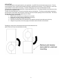
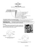
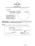
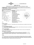
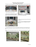
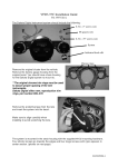
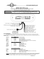
MODEL MCV-7000 series
SPEEDOMETER/TACHOMETER INFORMATION GAUGE
Please read this before beginning installation or wiring.
IMPORTANT NOTE! This gauge has an odometer preset option that is only available one time
within the first 100 miles (160 km) of operation. See ODOMETER PRESET MENU for instructions.
FUNCTION SWITCH
The switch on the left of the gauge changes the left side message display. The switch on the right of the gauge
changes the right side message display. To zero or reset any of the readings, press and hold the corresponding switch for a
couple seconds.
RIGHT: MILEAGE MENU
ODOMTR
>
000000
odometer mileage
TRIP A
>
A 000.0
trip meter mileage A
TRIP B
>
B 000.0
trip meter mileage B
SERVIC
>
S 0000
miles since last service (if programmed)
KPH
>
KPH 00
metric speed conversion (to mph if metric unit is selected)
PERFRM
>
switch to performance menu
RIGHT: PERFORMANCE MENU
HI RPM
>
H 0000
high rpm recall
HI SPD
>
HI 00
high speed recall
0-60 T
>
60 00.0
0-60mph time (0-100kph)
QUARTR
>
QT 00.0
quarter mile time
QT MPH
>
QT 00
quarter mile speed
MILES
>
switch to mileage menu
CLOCK
HOURS
RPM
OIL
VOLTS
LEFT: INFORMATION MENU
>
12:00
12 hour clock
>
HR 0.0
re-settable hour meter
>
R 0000
rpm reading in numeric display
>
OIL 00
displays current oil pressure (eliminated in oil switch mode)
>
V 00.0
displays voltage to gauge
Example: If the odometer mileage is currently displayed and you want to change to the 0-60 time, press and release
the right switch until “PERFRM” is displayed. Wait until the display switches to “HI RPM”. Press and release the
switch until “60 TIM” is displayed. After a couple of seconds the display will show the current 0-60 time.
MAN#650149C
MOUNTING
A mounting bracket must be purchased for your application. Any BKT-50xx series bracket may be used. The bar
mount brackets can be used for above-the-bar mounting or below-the-bar mounting. The 35° triple-tree mounts are
only available for above-the-bar mounting. The MCV-7300 gauge can only be mounted above the bar.
The triple-tree mounting bracket replaces the original handle bar mount. The gauge attaches to the back side of the
bracket with the supplied screws.
The bar mount brackets have a curved front bracket and two rear brackets. The longer screws attach the gauge to
the back side of the bracket and the shorter screws go into the recessed openings on the rear brackets. The mount
fits tight and will need to be pulled together by the screws.
To mount the gauge under the bar:
1. Remove the rear plate by unscrewing the four screws.
2. Rotate the rear plate so the mounting tab is on the top.
3. Reattach the rear plate using the four screws.
4. Place bar mount bracket on the handle bars so that the recessed screw holes are on the top.
5. Using the long screws, secure the gauge to the bottom side of the bar mount bracket.
Drawings for using bar mount brackets above the bar and below the bar.
(MCV-7300 can only be mounted above the bar.)
2
POWER
Connect the red wire from the 4-wire main harness to accessory power from the ignition switch. Connect
the WHITE/RED wire from the 4-wire main harness to constant battery power. The WHITE/RED wire keeps the
clock time and the RED wire lights up the gauge.
Never connect this to a battery charger alone. It needs to have a 12 volt battery connected to it. Battery
chargers have an unregulated voltage output that will cause the system to not operate properly.
GROUND
The BLACK wire from the 4-wire harness is the main ground for display system. A poor ground connection
can cause improper or erratic operation.
SPEEDOMETER
Failure to calibrate the speedometer may cause your odometer mileage to increase very rapidly.
The speed input connector plugs into the speed sensor to tell how fast you are traveling. On cable driven
applications, the SEN-6011 (sold separately) connects to the speedometer cable and provides the electric signal.
This sensor has a 5/8” coarse thread fitting that accepts mid-80’s and earlier cables directly. For newer cycles the
speedometer cable will need to be replaced with a cable having the correct fitting. Custom cables can be made, or
stock cables can be modified for many of the Metric applications.
With transmissions having the built-in electric sensor, the supplied three-wire harness adapter connects the
transmission speed sensor to the speedometer. This system will also accept most after-market inductive, Halleffect, or ground switch sensors.
For 3 wire Hall-effect sensors, refer to the installation instructions for the sensor to determine wire color
code. Most 3 wire sensors use the following color code: RED – power, BLACK – ground, WHITE – speed signal.
Connect the sensor signal wire to the GREEN wire from the 3-wire harness, connect the sensor power wire to the
red wire from the 3-wire harness, and connect the sensor ground wire to the black wire from the 3-wire harness.
For speed sensor integrated into a vehicle wiring harness(most Metric Cruisers w/factory VSS utilize a 3wire Hall-effect sensor), consult a service manual to determine the color code and location of the speedometer
signal. If the factory harness supplies +5V to the sensor, please utilize the factory connection in place of the
red power wire.
For 2004+ Harley and 2003 V-Rod applications make sure to simply ‘‘Tee’’ into the white wire on the speed
sensor to make certain the ECM will still receive its proper VSS signal from the sensor.
2006+ Sportsters utilize a black/blue wire for the VSS signal in place of the white wire on most big-twin models.
The speedometer is fully adjustable and calibration is described on page 5. VSS wires should be isolated
from the ignition system. Coils, plug wires, or tachometer signal wires routed near or with the VSS wire can cause:
erratic speedometer operation, speed reading at a standstill, incorrect or difficult calibration.
TACHOMETER
The tachometer is used by connecting the YELLOW wire from the main harness to the negative side of the
coil or to an ignition module tach output. The tachometer is adjustable for 1 – 15 cylinder settings. The 1 cylinder
setting is used for single-fire ignition systems without a buffered tach output.
For tach signals integrated into a vehicle wiring harness, consult a service manual to determine the color
code and location of the tachometer signal. The bar displays rpm x1000 with a range of 350 – 8000 rpm.
For 2004+ Harley and 2003 V-Rod
The tachometer signal will come from the negative side of the ignition coil. Blue/Orange for the front
cylinder, Yellow/Blue for the rear cylinder, connect the tachometer input to only one of these two wires, set the
tachometer for a 1 cyl signal, see Tachometer Set-up for instructions.
STATUS AND WARNING INDICATORS
The right turn, left turn, and high beam indicators are activated by a 12 volt input signal connected to the 8wire indicator harness. The right turn signal wire is GREEN, the left turn signal wire is ORANGE, and the high beam
wire is PURPLE. The indicator harness can be connected to the same wires that the stock indicator lights would be
connected to. The MCV-7000 wire colors may not match the wire colors in your electrical wire harness.
The neutral and check engine indicators are activated by a ground signal connected to the 8-wire indicator
harness. The check engine wire is WHITE/BLUE and the neutral wire is BLUE.
LOW VOLTAGE WARNING
When the voltage drops below the warning limit with the engine running, the battery indicator will illuminate.
(default warning limit is 11.0V)
OIL PRESSURE GAUGE
The oil pressure gauge uses the supplied oil pressure sender mounted in place of the original sender or
switch. A 1/4” NPT to 1/8" NPT is included to fit most Twin Cam applications. Most other applications will require
additional hardware. The GRAY wire from the 8-wire harness connects to the terminal on top of the sender. The
sender grounds through its mount threads and uses a tapered, dry-seal thread. (Pipe tape should not be used.)
When the oil pressure is below the warning limit the oil indicator will illuminate (default warning limit is 10psi). The
gauge can also be set up to work with a stock oil pressure warning switch, this must be changed to “SWITCH” if
our oil sensor is not used. See the OIL setup menu for instructions on changing this.
3
FUEL LEVEL GAUGE
An optional fuel level gauge is also available. It can be used with a fuel switch (default setting) or fuel
sender. The fuel sender can be a 240-33 ohm sender, 73-10 ohm sender, or can be programmed for a custom
sender range. The BROWN wire from the 8-wire harness connects to the fuel level sender. When connected to a
fuel sender, the fuel gauge lights up a series of bars next to the fuel pump symbol. When it is used with a fuel
switch, the fuel pump symbol will normally be off and will illuminate to indicate low fuel. If a low fuel switch is used it
may be necessary to connect a load resistor or bulb in order for the switch to operate correctly. One lead from the
bulb connects to accessory power and the other lead splices into the wire to the fuel switch.
CLOCK
The gauge has a 12 hour clock on the left message display. To view the clock press and release the left
switch until CLOCK is displayed. The clock is set by pressing and holding the left switch while the clock is displayed.
The minutes will begin flashing. Every time the left switch is momentarily pressed the minutes will increase by one.
Press and hold the left switch to change to the hours adjust. The hours will begin flashing and every time the left
switch is momentarily pressed the hours will increase by one. Press and hold the left switch to exit the clock setting.
NIGHT DIMMING
Your display system has a dimming feature that dims the display intensity automatically at night. Normally
the system is at full brightness for daytime viewing. To have the system at full brightness all of the time, go into the
DIM setup menu and select OFF instead of AUTO.
GAUGE SETUP AND CALIBRATION
The setup menus are entered by holding the left switch in while turning the key on. The menus are as
follows:
Main Menu
SPEED
Sub Menu
AUTO
ADJ
UNIT
SERVICE
TACH
ENGINE
WARN
SIGNAL
GEAR
VOLT
PROGRM
OFF
MODEL
VER
SP CAL
WARN
FUEL
SENDER
OIL
CUSTOM
WARN
INFO
DIM
CLOCK
DONE
AUTO
OFF
CAL 0
Description
auto calibrate speed
adjust calibrate speed
select mph or kph units
MPH
KPH
miles to service setting
500 – 7500 (in increments of 500), OFF
set engine cylinder setting
2 – 15
set rpm shift warning point
select normal or low voltage tach signal
NORMAL, LO VLT
transmission gear display selection
no gear display
Gauge model number
Gauge revision code
speed cal setting
set low volt warning point
9.5V – 12.5V
select sender type or switch input
75 – 10, 240 – 33, SWITCH, or CUSTOM (if programmed)
program custom fuel sender curve
set low oil pressure warning point or switch input selection
02 – 30 or SWITCH
automatic night dimming
no dimming
set clock time adjustment
resume normal operation
(NOTE: the custom sender range must be selected after programming).
4
SPEEDOMETER SETUP
Press and hold the left switch while turning the key on and starting the engine. Once the engine is running,
release the switch. When “SPEED” is displayed, press the switch again and then release it. The clock display
should switch between “AUTO”, “ADJUST”, “UNIT”, and “SERVIC”.
METRIC SELECTION
If you are setting the system up for metric displays, press the switch when “UNIT” is displayed.
Press and release the switch until “KPH” is displayed.
Press and hold the switch unit “DONE” is displayed.
SPEED CALIBRATION
There are two methods for calibrating the speedometer, auto cal and adjust. Either one can be used. Auto
cal requires that you have one measured mile marked out (km for metric). Adjust requires you to follow another
vehicle going at a set speed or timing your self over a mile to determine your speed.
Auto Cal
When “AUTO” is displayed press and release the switch. The clock display will show “AUTO” and the
message display will show zeroes. The MPH display will show nothing. You should now begin driving the
measured mile. The message display will count the number of pulses received from the sensor. The message
display cannot be used to determine when a mile has been driven. Once you reach the end of your marked mile,
press the switch again. The calibration is now done.
Adjust
When “ADJUST” is displayed press and release the switch. The system will restart with “ADJUST” on the
message display. The speedometer will show the speed reading. Begin driving at a known speed. When the
switch is pressed and held the speedometer reading will begin increasing until the switch is released. The next time
the switch is pressed and held the reading will begin decreasing until it is released. The new calibration will be
saved if no adjustments are made for 10 seconds.
MILES TO NEXT SERVICE SETUP
The service mileage is a countdown mile meter. The service mile display can be disabled or can be set to
count down from 500 – 7500 miles. If the service mile is enabled and 0 miles remains the gauge will display
“SERVIC DUE”. If the right push button switch is pressed and held while “SERVIC DUE” is displayed, the service
miles will be reset to the mileage value selected.
To change the service miles, enable, or disable the reading, go to the SPEED setup menu as described
above and then select “SERVIC”.
The current setting will be displayed. “OFF” or a mileage from 500 – 7500.
Press and release the switch until the desired setting is displayed.
Press and hold the switch until “DONE” is displayed.
TACHOMETER SETUP
The gauge can be set to read from 1-15 cylinder ignition signals. It can also be set to read either 12 volt
tach signals or 5 volt tach signals found on some engine computers. The rpm warning/shift point can be adjusted
from 2000 – 8000. The tachometer will read from 350 – 8000 rpm.
Press and hold the left switch while turning the key on. Release the switch. When “TACH” is displayed,
press the switch again and then release it. The message display should switch between “ENGINE”, “WARN”, and
“SIGNAL”.
Engine cylinder setup
When “ENGINE” is displayed press and release the switch.
The current cylinder setting will be displayed.
Press and release the switch until the desired setting is displayed.
Press and hold the switch until “DONE” is displayed.
Rpm warning setup
When “WARN” is displayed press and release the switch.
The current warning point will be displayed.
Press and release the switch until the desired setting is displayed.
Press and hold the switch until “DONE” is displayed.
Tach signal setup
When “SIGNAL” is displayed press and release the switch.
The setting will be displayed. (NORMAL or LO VOLT)
Press and release the switch until the desired setting is displayed.
Press and hold the switch until “DONE” is displayed.
5
GEAR INDICATOR SETUP
This gauge can optionally display the gear position. The gauge can learn the positions based on speed and
rpm. It will work with 3, 4, 5, or 6 speed transmissions.
To program the gear positions, begin at a section of road where you can gradually shift through all of the
gears. Press and hold the left switch while turning the key on and starting the engine. Once the engine is running,
release the switch. When “GEAR” is displayed, press the switch again and then release it.
The display will show the current selection, “OFF” or “PROGRM”. Press and release the switch to change
the selection.
To begin programming, when “PROGRM” is displayed, press and hold the switch. The message will show
“LO RPM” if the engine rpm is below 1500, or “LO SPD” if the vehicle speed is below 5.
st
Begin driving in 1 gear. The display should show “LEARN” and the “1” should be flashing. Drive at a
steady speed until the “1” stops flashing and the display shows “SHIFT”.
nd
Shift to 2 gear and drive at a steady speed. When the “2” stops flashing and the display shows “SHIFT”,
rd
go on to 3 gear.
rd
Repeat this through each gear. After 3 gear, if you stop or shift to neutral the gear settings will be saved
and the display will show “DONE”
Press and release the left switch to restart the gauge in normal operation.
INFO MENU
The INFO menu is used to get the gauge model number, gauge revision code, and speed cal setting. This
will normally only be used for diagnostic and troubleshooting.
VOLT MENU
The VOLT menu changes the low voltage warning point. Press and hold the left switch while turning the key
on. Release the switch. When “VOLT” is displayed, press the switch again and then release it. The message
display will show “WARN”. Press and release the switch to view or change the current warning point. The display
will show “LO 11.0”. Press and release the switch to change the warning point, press and hold the switch to save
the new warning point.
FUEL MENU
The FUEL menu changes the fuel gauge setup. Press and hold the left switch while turning the key on.
Release the switch. When “FUEL” is displayed, press the switch again and then release it. The message display
will switch between “SENDER”, and “CUSTOM”.
To change the fuel sender selection, press and release the switch when “SENDER” is displayed. The
current setting will be displayed. The 4 settings are: “SWITCH”, “CUSTOM”, “75 – 10”, “240 – 33”. (SWITCH
should be selected if this gauge is not being used.)
To program a custom fuel sender curve, press and release the switch when “CUSTOM” is displayed. You
will either need the fuel sender out of the tank, or have the tank empty and add fuel during the programming
procedure. The left display will “SET 00” and the right display will show the current sender resistance.
With the sender in the empty position, press and release the switch.
The display will show “SET 33”. Move the sender to 1/3 tank position and press and release the switch.
The display will show “SET 66”. Move the sender to 2/3 tank position and press and release the switch.
The display will show “SET 99”. Move the sender to the full position and press and release the switch.
OIL MENU
The OIL menu changes the low oil pressure warning point. Press and hold the left switch while turning the
key on. Release the switch. When “OIL” is displayed, press the switch again and then release it. The message
display will show “WARN”. Press and release the switch to view or change the current warning point. The display
will show “LO 10” or “SWITCH”. Press and release the switch to change the warning point, press and hold the
switch to save the new warning point. Selecting “SWITCH” allows it to work with a stock pressure warning switch.
DIM MENU
The DIM menu selects whether the unit automatically dims at night or remains at full brightness all of the
time. Press and hold the left switch while turning the key on. Release the switch. When “DIM” is displayed, press
the switch again and then release it. The current setting will be displayed, “AUTO” or “OFF”. Press and release the
switch to change the setting, press and hold the switch to save the setting.
CLOCK MENU
The CLOCK menu sets the fine adjustment for clock calibration. The clock will typically be accurate to
within ±2 minutes a month. This setting allows the time to be fine tuned by ± 7 seconds/day. Press and hold the
left switch while turning the key on. Release the switch. When “CLOCK” is displayed, press the switch again and
then release it. The display will show “CAL 0”. Press and release the switch to change the cal value, press and hold
the switch to save the setting.
6
ODOMETER PRESET MENU
The odometer can be preset one time by the customer within the first 100 miles. Once the odometer has
more than 100 miles the menu option will no longer be displayed. Make sure you have first calibrated the
speedometer and correctly selected the units to be either MPH or km/h first. The odometer will be set in the
selected units. Once you have preset the miles you cannot change it again. WARNING!!: This only allows
setting odometer to the nearest mile. Do not use tenths! For example a mileage of 65432.1 should be set to
“065432” using this method. If the tenths digit is used, the odometer will read 10 times too high.
• Press and hold the left switch while turning the key on. Release the switch.
• When “-ODOM-” is displayed, press the left switch again and then release it.
• The current miles will be displayed on the right side message display with the left most digit flashing.
• Press and release the left switch to increment the digit. Press and hold the switch to move to the next digit to
the right. Continue until the right most digit has been set.
• Press and hold the left switch until the left message display shows “REDO”.
•
If the mileage setting is wrong press and hold the left switch while “REDO” is displayed to go back and continue
changing the odometer display, or turn the key off to cancel any changes.
• If the mileage setting is correct press and release the left switch to change the display to “SAVE”.
• Now press and hold the switch while “SAVE” is displayed to save the current odometer reading.
Troubleshooting guide.
Problem
Gauge will not light up
Possible cause
Red wire does not have power.
Black wire is not getting a good ground.
Gauge is damaged.
Harness is not connected properly.
Speed sensor not grounded properly.
Solution
Connect to a location that has power.
Connect ground to a different location.
Return gauge for repair. (see instructions)
Gauge lights up, but speed
Check connection from speed harness to speed sensor and gauge.
will only show zero.
Move ground to different location, preferable close to the
speedometer ground.
Speed sensor is not being turned by
Check cable connection between sensor and cable drive.
the cable.
Sensor can be tested by spinning the cable with a drill.
Sensor is not sending a speed signal. See speed sensor voltage checks listed below.
Gauge is not calibrated
Gauge must be recalibrated (see instructions).
PLEASE – SET – SPEED
Speedometer is not calibrated.
Gauge must be calibrated to your bike (see instructions)
Speed reading is erratic or
Speed sensor wire is loose or broken. Check all wire connections and inspect wire for breaks.
jumps around.
Cable is loose or broken.
Check cable between sensor and transmission.
Poor ground connection.
Check ground connection on speedometer and sensor.
Speed reading is incorrect.
Gauge is not calibrated correctly.
Gauge must be calibrated (see instructions).
Gauge lights up, but tach
Tach wire is not connected properly.
Check connection from yellow wire to tach signal wire.
will only show zero.
Ignition system not grounded properly. Check engine and ignition system grounds.
Gauge is not grounded properly.
Check gauge and engine grounds.
Tach signal type is not set correctly.
Change the signal type as described in the TACHOMETER SETUP.
Gauge is not calibrated
Gauge must be recalibrated (see instructions).
Tach reading is erratic or
Tach signal wire is loose or broken.
Check all wire connections and inspect wire for breaks.
jumps around.
Poor ground connection.
Check ground connection on tachometer and engine.
Tach reading is incorrect.
Gauge is not calibrated correctly.
Gauge must be calibrated (see instructions).
High beam, Left turn, or Right Loose or incorrect connection to
Check that the appropriate indicator wire has about 0 volts when the
turn indicator does not work. indicator wire.
indicator should be off and about 12 volts when the indicator should be
on.
Neutral, low oil, or engine
Loose or incorrect connection to
Check that the appropriate indicator wire has about 12 volts when the
indicator does not work.
indicator wire.
indicator should be off and about 0 volts when the indicator should be
on.
Oil pressure gauge is
Gray wire is not connected properly.
Check connection from gray wire to pressure sender.
incorrect or erratic.
Oil pressure sender is getting a poor
The sender grounds through its mounting threads. Make sure the
threads
ground connection.
and fittings are clean.
Fuel level gauge is
Brown wire is not connected properly. Check connection from brown wire to fuel level sender.
incorrect or erratic.
Fuel sender is getting a poor ground.
Check ground connections to fuel sender mounting plate and sender.
Gauge is not set correctly.
Select a different fuel sender range or use the custom sender setup.
Low fuel indicator does not
Fuel switch requires additional load.
A stock low fuel switch may require a light bulb or load resistor
connected
work.
to accessory power to work correctly.
Turn signals do not cancel
Output speed signal to stock cancel
Check the connections on the solid white wire coming from the gauge.
automatically.
unit is loose or not connected properly.
Speedometer is not calibrated.
Calibrate the speedometer.
Speed sensor is not working.
If the speedometer always shows zero, check speed sensor voltages.
Turn signal cancel unit is not working. Test turn signal module according to the bike’s service manual.
7
Speed sensor voltage checks. All checks should be made with the sensor connected to the gauge and the key
on. Checks should be done with a volt meter and not a test light.
3-wire sensor: Red wire should have 9-11 volts dc, slightly less than battery voltage.
Black wire should show ground, 0 volts dc at all times.
White wire should vary between 0 and 5 volts dc as the gear teeth pass by the sensor.
2-wire sensor: Measure the voltage between the two sensor wires. With the wheel spinning the voltage should be
about 1-10 volts ac (make sure the meter is set to AC volts and not DC volts for this check).
WIRING COLOR CODE FOR GAUGE:
MCV-7000 4-wire
Stock HD® harness color
Function
RED
ORANGE/WHITE
+12 volt with key on
WHITE/RED
Constant fused +12V battery power
BLACK
BLACK
ground (connect directly to battery negative)
YELLOW
PINK
tachometer signal
MCV-7000 8-wire
Stock HD® harness color
Function
PURPLE
WHITE
High Beam indicator
ORANGE
VIOLET
Left Turn indicator
GREEN
BROWN
Right Turn indicator
BLUE
TAN
Neutral indicator
GRAY
GREEN/YELLOW
Low Oil Pressure indicator
WHITE/BLUE
BLACK/YELLOW
“ENGINE” indicator
WHITE
WHITE/GREEN
output speed signal
BROWN
fuel level sensor or switch
MCV-7000 3-wire
Stock HD® harness color
Function
RED
RED
+12 power to sensor
BLACK
BLACK
ground for sensor
GREEN
WHITE
speed signal
***The HD® wire colors provide are for reference, please consult service manual for verification
SERVICE AND REPAIR
DAKOTA DIGITAL offers complete service and repair of its product line. In addition, technical consultation is available to help you work through any
questions or problems you may be having installing one of our products. Please read through the Troubleshooting Guide. There, you will find the solution to most
problems.
Should you ever need to send the unit back for repairs, please call our technical support line, (605) 332-6513, to request a Return Merchandise Authorization
number. Package the product in a good quality box along with plenty of packing material. Ship the product by UPS or insured Parcel Post. Be sure to include the
RMA number on the package, and include a complete description of the problem with RMA number, your full name and address (street address preferred), and a
telephone number where you can be reached during the day. Any returns for warranty work must include a copy of the dated sales receipt from your place of purchase.
Send no money. We will bill you after repair.
Dakota Digital 24 Month Warranty
DAKOTA DIGITAL warrants to the ORIGINAL PURCHASER of this product that should it, under normal use and condition, be proven defective in material
or workmanship within 24 MONTHS FROM THE DATE OF PURCHASE, such defect(s) will be repaired or replaced at Dakota Digital’s option.
This warranty does not cover nor extend to damage to the vehicle’s systems, and does not cover removal or reinstallation of the product. This Warranty
does not apply to any product or part thereof which in the opinion of the Company has been damaged through alteration, improper installation, mishandling, misuse,
neglect, or accident.
This Warranty is in lieu of all other expressed warranties or liabilities. Any implied warranties, including any implied warranty of merchantability, shall be
limited to the duration of this written warranty. Any action for breach of any warranty hereunder, including any implied warranty of merchantability, must be brought
within a period of 24 months from date of original purchase. No person or representative is authorized to assume, for Dakota Digital, any liability other than expressed
herein in connection with the sale of this product.
8