1
ASCENT TRAINER &
ELLIPTICAL
OWNER’S MANUAL
1
A3x_E3xc_rev1.7.indd 1
8/6/10 2:33 PM
A3x_E3xc_rev1.7.indd 2
8/6/10 2:33 PM
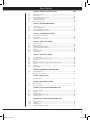
Table
A3x_E3xc_rev1.7.indd 3
of
Contents
CHAPTER 1: IMPORTANT SAFETY INSTRUCTIONS
PAGES
1.1
1.2
1.3
1.4
1.5
1.6
Before Getting Started .............................................................................................. 01
Proper Usage ........................................................................................................... 01
Read and Save These Instructions ............................................................................. 01
Electrical Requirements ........................................................................................... 01
Installation Requirements ......................................................................................... 02
Grounding Instructions ............................................................................................. 02
CHAPTER 2: PREVENTATIVE MAINTENANCE
2.1
2.2
2.3
2.4 Cleaning Tips ........................................................................................................... 02
Check for Damage Parts ............................................................................................. 02
Care and Maintenance Instructions ............................................................................ 03
Preventative Maintenance Check List ......................................................................... 03
CHAPTER 3: USING MANAGER PREFERENCE
3.1
3.2
3.3
Using Manager Preference Mode ................................................................................ 04
Using CSAFE ............................................................................................................ 04
Using (Back Side) Access layout ................................................................................ 04
CHAPTER 4: USING THE E3xc CONSOLE
4.1
4.2
4.3
4.4
4.5
4.6
4.7
Console Description ................................................................................................. 05
Manual Operation .................................................................................................... 05
Operating Level Based Programs ................................................................................ 05
User Defined Programs - Random ............................................................................. 05
Fit Test ................................................................................................................... 06
Heart Rate Control ................................................................................................... 07
Constant Watts ......................................................................................................... 07
CHAPTER 5: USING THE A3x CONSOLE
5.1
5.2
5.3
5.4
5.5
5.6
5.7
5.8
Console Description ................................................................................................. 08
Incline Function (Ascent Trainer Only) ....................................................................... 08
Quick Start .............................................................................................................. 09
Manual ................................................................................................................... 09
User Defined Programs - Rolling, Interval, Fatburn & Random ..................................... 09
Fit Test ................................................................................................................... 10
Target HR ................................................................................................................. 11
Constant Watts ........................................................................................................ 11
CHAPTER 6: PROGRAMMING & ENGINEERING MODE
6.1
6.2
Using Manager Mode ............................................................................................... 12
Manager Screen Descriptions ................................................................................... 12
7.1
A3x Ascent Trainer .................................................................................................. 14
CHAPTER 8: SERIAL NUMBER LOCATION
8.1
8.2
A3x Ascent Trainer .................................................................................................. 14
E3xc Incline Elliptical ............................................................................................. 14
CHAPTER 9: A3x SPECIFICATIONS AND ASSEMBLY STEPS
9.1
9.2
9.3
9.4
9.5
Model Specifications ...............................................................................................
Fasteners ............................................................................................................
Assembly Steps ......................................................................................................
Optional Entertainment Accessory ............................................................................
Leveling the Unit ....................................................................................................
CHAPTER 10: E3xc SPECIFICATIONS AND ASSEMBLY STEPS
10.1
10.2
10.3
10.4
Model Specifications ...............................................................................................
Fasteners ...........................................................................................................
Assembly Steps ......................................................................................................
Optional Entertainment Accessory ............................................................................
CHAPTER 7: MOVING THE UNIT
15
16
17
19
19
20
21
22
25
8/6/10 2:33 PM
A3x_E3xc_rev1.7.indd 4
8/6/10 2:33 PM
CHAPTER 1: Important Safety Instructions
1.1 BEFORE GETTING STARTED
It is the sole responsibility of the purchaser of Matrix Fitness Systems products to instruct all individuals, whether they are the end user or supervising personnel, on proper usage of the equipment.
It is recommended that all users of Matrix Fitness Systems exercise equipment be informed of the following information prior to its use.
• Keep any power cord away from heated surfaces.
• Close supervision is necessary when elliptical is used by or near children
or disable persons.
• Do not use outdoors
• Do not operate where aerosol (spray) products are being used or when oxygen is being administered.
1.2 PROPER USAGE
• To disconnect, turn all controls to the off position, then remove plug from
outlet.
• Do not use the equipment in any way other than designed or intended by
• Connect this elliptical to a properly grounded outlet only.
the manufacturer. It is imperative that all Matrix Fitness Systems equipment is used properly to avoid injury.
• Keep hands and feet clear of moving parts at all times to avoid injury.
• Unsupervised children must be kept away from this equipment.
• Do not wear loose clothing while on equipment.
1.3
READ AND SAVE
THESE INSTRUCTIONS
This elliptical is intended for commercial use. To ensure your safety and
protect the equipment, read all instructions before operating the MATRIX
elliptical.
When using an electrical product, basic precautions should always be followed including the following:
DANGER
: To reduce the risk of electric shock: Always unplug
this equipment from the electrical outlet immediately after using and before cleaning.
WARNING
: To reduce the risk of burns, fire, electrical shock or
injury to persons that may be associated with using this product.
• This unit is not equipped with a free wheel. Pedal speed should be reduced in
a controlled manner.
• Care should be used when mounting or dismounting the equipment. Before
mounting or dismounting move the pedal on the mounting or dismounting side
to its lowest position and bring the machine to a complete stop.
CAUTION
: If you experience chest pain, nausea, dizziness or
shortness of breath, STOP exercising immediately and consult a physician
before continuing.
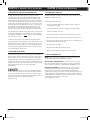
1.4 ELECTRICAL REQUIREMENTS
The Matrix Elliptical is designed to be self-contained and does not require
an external power supply to operate. The battery needs to be charged for 3-4 hours when first installed. Until
the battery is fully charged, the 30 second pause feature may not function
fully. The charging does not need to be continuous for 3-4 hours, but over combined workouts equaling 3-4 hours.
The Ascent Trainer does require an external AC power source.
For your safety and Ascent performance, the ground on this circuit must
be non-looped. Please refer to NEC article 210-21 and 210-23. The Ascent
Trainer is provided with a power cord with a plug listed below and requires
the listed outlet. Any alterations of this power cord could void all warranties
of this product. Multiple Ascent trainers can be powered on one dedicated
circuit. (3 units per 15 Amp and 4 units per 20 Amp dedicated circuit.)
• An appliance should never be left unattended when plugged in. Unplug
from outlet when not in use and before putting on or taking off parts.
• This product must be used for its intended purpose described in this
lower case owner’s manual. Do not use other attachments that are not
recommend by the manufacturer. Attachments may cause injury.
• To prevent electrical shock, never drop or insert any object into any opening
120 NEMA 5-20R
120 NEMA 5-20R
220 NEMA 6-20R
220 NEMA 6-20R
• Do not remove the console covers. Service should only be done by an
authorized service technician.
• Never operate the elliptical with the air opening blocked. Keep the air
opening clean, free of lint and hair.
• Never operate product if it has a damaged cord or plug, if it is working
properly, if it has been damaged, or immersed in water. Return the unit to
a service center for examination and repair.
• Do not carry this unit by it’s supply cord or use the cord as a handle.
1
A3x_E3xc_rev1.7.indd 1
8/6/10 2:33 PM
CHAPTER 1: Important Safety Instructions
CHAPTER 2: Preventative Maintenance
1.5 DEDICATED CIRCUIT/ELECTRICAL REQUIREMENT INFO
2.1 RECOMMENDED CLEANING TIPS
All Matrix Ascent Trainers require the use of a 15 amp or 20 amp
“dedicated circuit,” with a non-looped (isolated) neutral/ground, for the
power requirement. Quite simply this means that each outlet you plug
Ascent Trainers into should not have anything else running on that same
circuit besides other Ascent trainers (up to 3 per 15 amp circuit and 4 per
20 amp circuit). The easiest way to verify this is to locate the main circuit
breaker box, and turn off the breaker(s) one at a time. Once a breaker has
been turned off, the only thing that should not have power to it are the
Ascent trainers in question. No lamps, vending machines, fans, sound
systems, or any other item should lose power when you perform this test.
Preventative maintenance and daily cleaning will prolong the life and look of your
MATRIX Ascent Trainer or Elliptical.
Please read and follow these tips.
• P
osition the equipment away from direct sunlight. The intense UV light can
cause discoloration on plastics.
• Locate your equipment in an area with cool temperatures and low humidity.
Non-looped (isolated) neutral/grounding means that each circuit must have
an individual neutral/ground connection coming from it, and terminating
at an approved earth ground. You cannot “jumper” a single neutral/ground
from one circuit to the next. • Clean with a soft 100% cotton cloth.
In addition to the dedicated circuit requirement, the proper gauge wire
must be used from the circuit breaker box, to each outlet that will have the
maximum number of units running off of it. If the distance from the circuit
breaker box, to each outlet, is 100 ft or less, then 12 gauge wire may be
used. For any distance greater than 100 ft from the circuit breaker box to
the outlet, 10 gauge wire must be used.
• D
o not pour liquids directly onto your equipment. This can cause damage to the
equipment and in some cases electrocution.
1.6 GROUNDING INSTRUCTIONS
The elliptical must be grounded. If it should malfunction or breakdown,
grounding provides a path of least resistance for electric current to reduce
the risk of electric shock. The elliptical is equipped with a cord having an
equipment-grounding conductor and a grounding plug. The plug must be
plugged into an appropriate outlet that is properly installed and grounded in
accordance with all local codes and ordinances. If the user does not follow
these grounding Instructions, the user could void the Matrix limited warranty.
DANGER
: Improper connection of the equipment-grounding
conductor can result in the risk of electric shock. Check with a qualified
electrician or serviceman if the user is in doubt as to whether the product
is properly grounded. Do not modify the plug provided with the product if it
will not fit the outlet; have a proper outlet installed by a qualified technician.
• Clean with soap and water or other non-ammonia based all purpose cleaners.
• Wipe foot pads, handles, heart rate grips, and handlebars clean after each use.
• Check pedal motion and stability.
• Adjust leveling feet when equipment wobbles or rocks.
• Maintain a clean area around equipment, free from dust and dirt.
2.2 CHECK FOR DAMAGED PARTS
DO NOT use any equipment that is damaged or has worn or broken parts. Use
only replacement parts supplied by Matrix Fitness Systems.
MAINTAIN LABELS AND NAMEPLATES. Do not remove labels for any reason.
They contain important information. If unreadable or missing, contact Matrix
Fitness Systems for a replacement. 1-866-693-4863, www.matrixfitness.com
MAINTAIN ALL EQUIPMENT Preventative maintenance is the key to smooth
operating equipment. Equipment needs to be inspected at regular intervals.
Defective components must be replaced immediately. Improperly working
equipment must be kept out of use until it is repaired. Ensure that any person(s)
making adjustments or performing maintenance or repair of any kind is qualified
to do so. Matrix Fitness Systems will provide service and maintenance training at
our corporate facility upon request or in the field if proper arrangements are made.
2
A3x_E3xc_rev1.7.indd 2
8/6/10 2:33 PM
CHAPTER 2:
Preventative Maintenance
2.3 CARE AND MAINTENANCE INSTRUCTIONS
2.4 PREVENTATIVE MAINTENANCE CHECKLIST
In order to maximize life span, and minimize down time, all MATRIX equipment
requires regular cleaning, and maintenance items performed on a scheduled
basis. This section contains detailed instructions on how to perform these items,
the frequency of which they should be done, and a check list to sign off each
time service is completed for a specific machine. Some basic tools and supplies
will be necessary to perform these tasks which include (but may not be limited to):
Facility:
Metric Allen wrenches
#2 Phillips head screwdriver
Adjustable wrench
Torque wrench (capability to read foot lbs, and inch lbs)
Lint free cleaning cloths
Teflon based spray lubricant
Mild, water soluble, detergent – such as “Simple Green”, or other Matrix
approved product
Teflon based spray lubricant such as “Super Lube”, or other Matrix approved
product
Vacuum cleaner w/extendable hose and crevasse tool attachment
Please find the worksheet sample for our equipment provided in this manual
and make copies as needed, keeping them up to date as the required service/
maintenance items are performed. It is critical that you also log the accumulated
(total) amount of miles or running hours on the equipment each time service or
maintenance is performed.
You may periodically see addendums to this document, as the Matrix Technical
Support Team identifies items that require specific attention, the latest version
will always be available on the Matrix website, matrixfitness.com
MAKE:
MODEL:
LOCATION:
TECHNICIAN:
S/N
DATE:
Inspect power cords
Check resistance system
Clean/lube guide rods
Check E-stop cord/button
Lubricate pivot points
Inspect belt/cable assy.
Vacuum/clean under cover
Check connecting joints
Check locking pins
Check motor drive belt
Remove covers, check belts
Check pulleys
Check running belt
Check pedal & crank
Inspect upholstery
Flip/replace deck
Check/lube seat adjustment
Check/tighten hardware
De-wax rollers
Verify electronics operation
Lubricate Acme screw
Notes/comments
MAKE:
MODEL:
LOCATION:
TECHNICIAN:
S/N
DAILY MAINTENANCE ITEMS
1)
Clean entire machine use water and mild detergent such as “Simple
Green”, or other Matrix approved solution (cleaning agents should be
alcohol and ammonia free).
DATE:
QUARTERLY MAINTENANCE ITEMS
Inspect power cords
Check resistance system
Clean/lube guide rods
1)
Check all connecting joint areas for tightness of bolt assemblies.
Check E-stop cord/button
Lubricate pivot points
Inspect belt/cable assy.
2)
Ensure that there is little, or no free play at all joint assemblies once bolts
have been tightened. Installation of washer kits may be required if free play
does not come out from tightening bolts.
Vacuum/clean under cover
Check connecting joints
Check locking pins
Check motor drive belt
Remove covers, check belts
Check pulleys
Check running belt
Check pedal & crank
Inspect upholstery
Flip/replace deck
Check/lube seat adjustment
Check/tighten hardware
De-wax rollers
Verify electronics operation
Lubricate Acme screw
3)
4)
Remove plastic covers, and lubricate ball joint where the Link Arm and
Handlebar join together. A grease gun, with a needle fitting adapter is
required for this (Matrix recommends using Superlube brand grease with
PTFE {Teflon} additive).
Remove plastic covers, and lubricate Acme screw on left and right incline
motors (Matrix recommends using Superlube brand grease with PTFE
{Teflon} additive). See section 9.11 for incline motor access instructions.
Notes/comments
3
A3x_E3xc_rev1.7.indd 3
8/6/10 2:33 PM
CHAPTER 3: Using Manager Preference
3.1 USING MANAGER PREFERENCE MODE
3.2 USING CSAFE
Your Matrix Elliptical is designed to allow you to customize settings for your
preferences and diagnostics. The Manager Mode can only be accessed while
the Elliptical is powered up. Follow the instructions to adjust the Elliptical
computer to your desired setting.
Matrix is the leader in entertainment availability. On the back of the console
are two RJ45 receptacles. They are marked CSAFE and ENTERTAINMENT.
STEP 1: Power up the Elliptical and hold the UP and DOWN ARROW KEYS
Use the CSAFE port to plug in a CSAFE device using an RJ45 connector.
The connection is as follows:
for 3 seconds. The word “Manager” will appear in the alphanumeric window and will enter into the Manager setting automatically after 3 seconds. Continue to pedal until finished.
STEP 2: Select information you would like to view or change from the
following list by using the UP or DOWN ARROWS. Press SELECT.
Manager mode will allow you to view and set the following:
MIN.
5
5
L1
60lbs
Miles
BI
On
On
3.3 USING (BACK SIDE) ACCESS LAYOUT:
Below is a layout to all of the access ports on the back of your Matrix
Console.
REPROGRAMMING
CONNECTOR
STEP 3: Use UP or DOWN ARROWS to increase or decrease values.
STEP 4: Press START to save and enter selected values and exit to STEP 2.
STEP 5: Exit by pressing START. Screen will reset to start up.
CSAFE
PORT
CSAFE
ENTERTAINMENT
PORT
ENTERTAINMENT
BATTERY
LOCATION
4
A3x_E3xc_rev1.7.indd 4
8/6/10 2:33 PM
CHAPTER 4: Using The E3xc Console
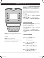
4.1 CONSOLE DESCRIPTION
4.2 MANUAL OPERATION
QUICK START: start pedaling and press “GO” to being your workout. All
energy expenditure values will be calculated using the default weight measurement.
MANUAL MODE: Manual is a workout that allows you to manually adjust the
resistance at any time. The manual workout also contains a setup screen
which allows you to input your weight to help calculate a more accurate
caloric burn rate.
•
•
•
•
Press “MANUAL”.
Enter your desired “TIME” using the ARROW KEYS or NUMBER KEYPAD and press ENTER.
Enter your desired “LEVEL” using the ARROW KEYS or NUMBER
KEYPAD and press ENTER.
Enter your “WEIGHT” using the ARROW KEYS or NUMBER KEYPAD and press ENTER.
4.3 OPERATING LEVEL BASED PROGRAMS
“Your Matrix Cycle offers versatile programs to keep the user motivated. The following instructions will guide you through the simple steps to select
Intervals, Rolling, Fat Burn and Random workouts.
PROGRAMS: Simple program selection buttons make Matrix Cycles easy to
•
•
•
•
Press the Workout Button of choice.
Enter your desired “TIME” using the ARROW KEYS or NUMBER KEYPAD and press ENTER.
Enter your desired “LEVEL” using the ARROW KEYS or NUMBER
KEYPAD and press ENTER.
Enter your “WEIGHT” using the ARROW KEYS or NUMBER KEYPAD and press ENTER.
use. Matrix Cycles feature eight programs.
4.4 USER DEFINED PROGRAMS - RANDOM
START/QUICK START: One Touch Quick Start and Start any time during pref-
RANDOM - there are 20 workout profiles in RANDOM mode. Profile will change
each time RANDOM key is pressed. Select a workout profile, follow user
informantion prompts or press QUICK START key to begin.
erence selection.
UP/DOWN: Easy information and level selection.
SELECT/SELECT SCREEN/ RESET: This multi-function button enters informa-
tion when setting up programming options, toggles information displayed and
if held down for 5 seconds, resets the Cycle to Start-up mode.
STEP 1: Select the PROGRAM button.
Press SELECT or wait 5 seconds.
Selecting START will start program.
STEP 2: Select TIME by using the UP or DOWN arrow keys.
Press SELECT or wait 5 seconds.
Selecting START will start program.
STEP 3: Select LEVEL by using the UP or DOWN arrow keys.
You can change the level at any time during workout.
Press SELECT or wait 5 seconds.
Selecting START will start program.
STEP 4: Select weight by using the UP or DOWN arrow keys.
Press START or SELECT to begin workout.
Display, Starting 3, Starting 2, Starting 1.
5
A3x_E3xc_rev1.7.indd 5
8/6/10 2:33 PM
CHAPTER 4: Using The E3xc Console
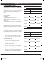
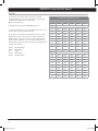
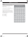
4.5 FIT TEST
This test measures cardiovascular fitness and proves an estimated sub-maximal VO2 result. It is based on power output according to ACSM
standards and was developed by the Cooper Institute (© www.cooperinstitute.org)
User RPMs must remain between 60-80 RPM during the test.
The test will end when the user can no longer maintain this speed. Use of a
heart rate strap is optional but provides more data.
The test starts at a low intensity level and gradually increases in intensity
(difficulty) every 2 minutes. As it increases, the user must maintain 6080RPM to advance to the next level. The test could take upwards of 30+
minutes for very fit individuals. Once the test ends a recovery period (cool
down) will begin and the user’s results are calculated and displayed. Results
are based on the following:
10-20%
30-40%
50% 60-70%
80-90%
- Well Below Average
- Below Average
- Average
- Above Average
- Well Above Average
Percentile Values for Maximal Aerobic Power
Age
Percentile
20-29
30-39
40-49
50-59
60+
90
51.4
80
48.2
50.4
48.2
45.3
42.5
46.8
44..1
41.0
70
38.1
46.8
44.6
41.8
38.5
35.3
60
44.2
42.4
39.9
36.7
33.6
50
42.5
41.0
38.1
35..2
31.8
40
41.0
38.9
36.7
33.8
39.2
30
39.5
37.4
35.1
32.3
28.7
20
37.1
35.4
33.0
30.2
26.5
10
34.5
32.5
30.9
28.0
23.1
90
44.2
41.0
39.5
35.2
35.2
80
41.0
38.6
36.3
32.3
31.2
70
38.1
36.7
33.8
30.9
29.4
60
36.7
34.6
32.3
29.4
27.2
50
35.2
33.8
30.9
28.2
25.8
40
33.8
32.3
29.5
26.9
24.5
30
32.3
30.5
28.3
25.5
23.8
20
30.6
28.7
26.5
24.3
22.8
10
28.4
26.5
25.1
22.3
20.8
Men
Women
6
A3x_E3xc_rev1.7.indd 6
8/6/10 2:33 PM
CHAPTER 4: Using The E3xc Console
4.6 HEART RATE CONTROL
4.7 CONSTANT WATTS
Your Matrix Ascent Trainer / Elliptical offers a heart rate control workout
mode. The heart rate control workout mode allows the user to program their
desired heart rate zone and the machine will adjust the resistance automatically based on the user’s heart rate. The heart rate zone is calculated using
the following equation: (220-Age)*% = target heart rate zone. The user must
wear a telemetric heart rate monitor or continually hold onto the contact
heart rate grips for this workout.”
CONSTANT WATTS workout is a unique program that allows you to vary your
cadence or RPM and the machine’s resistance will adjust accordingly to your
selected goal. The quicker you stride the less resistance for the goal selected.
•
•
•
•
•
Press “TARGET HEART RATE”.
Enter your “AGE” using the ARROW KEYS or NUMBER KEYPAD and press ENTER.
Enter your desired percentage of maximum heart rate using the ARROW KEYS or NUMBER KEYPAD and press ENTER.
Enter your desired “TIME” using the ARROW KEYS or NUMBER KEYPAD and press ENTER.
Enter your “WEIGHT” using the ARROW KEYS or NUMBER KEYPAD and press ENTER (user weight is used to calculate the caloric expenditure
during the workout).
•
•
•
•
Press “CONSTANT WATTS”
Enter your desired “WATT” using the ARROW KEYS or NUMBER KEYPAD and press ENTER (25 – 525).
Enter your desired “TIME” using the ARROW KEYS or NUMBER KEYPAD and press ENTER.
Enter your “WEIGHT” using the ARROW KEYS or NUMBER KEYPAD and press ENTER.
7
A3x_E3xc_rev1.7.indd 7
8/6/10 2:33 PM
CHAPTER 5: Using The A3x Console
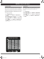
5.1 CONSOLE DESCRIPTION
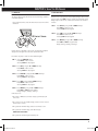
5.2 INCLINE FUNCTION (ASCENT TRAINER ONLY)
All programs follow the same basic steps.
Changing the incline will produce a wide variety of challenging workouts.
At 0 incline, you can expect a smooth, easy and low-impact pedal motion.
At higher incline levels, longer stride and higher step-up challenge the user
with a more focused glute workout.
• Select program key.
• Enter user information (age, weight).
• Choose workout time.
• How the incline works A3x - by pressing the UP elevation arrow key(inwhite)
both incline arms pivot towards the rear of the machine. This increases both
stride length and step on height.
• Choose resistance level.
• Select START.
Time
Speed
Distance
Calories
RPM
Watts
Elevation
Heart Rate
Select screen
Hold to reset
Quick start
start
Level
select
Incline
• Incline settings - There are 20 incline levels. One key press will change the incline in 5% increments. The console will disply 0-100, which
represents total percentage of incline. LED display 25 is 25% of total
incline, 50 is 50% of the total incline and so on. Upper LED changes
on each key press, showing incline changes.
WARNING
The heart rate displayed may be inaccurate
and should be used for reference only.
CAUTION
Consult a physician before using this equipment. Stop
exercising if you feel pain, faint, dizzy or short of breath.
WARNING
The heart rate displayed may be inaccurate
and should be used for reference only.
CAUTION
Consult a physician before using this equipment. Stop
exercising if you feel pain, faint, dizzy or short of breath.
Manual
Random
Manual
Random
Rolling
Hills
Fitness
Test
Rolling
Hills
Fitness
Test
Interval
Training
Heart
Rate
25%
Fat
Burn
Constant
Watts
Interval
Training
Heart
Rate
50%
Fat
Burn
1.866.693.4863 www.matrixfitness.com
Time
Speed
Distance
Calories
RPM
Watts
1.866.693.4863 www.matrixfitness.com
Elevation
Heart Rate
Select screen
Hold to reset
Quick start
start
Level
Incline
Start pedaling to view operating instructions
Constant
Watts
select
Time
Speed
Distance
Calories
RPM
Watts
Select screen
Hold to reset
Quick start
start
Elevation
Heart Rate
Level
Incline
select
Start pedaling to view operating instructions
Program selection can be changed at any time during a workout. This means
that the user can switch between RANDOM, MANUAL or several programs
without losing accumulated workout time or data.
• However, the console must be reset before starting FIT TEST, TARGET
HR, AND CONSTANT WATTS programs.
8
A3x_E3xc_rev1.7.indd 8
8/6/10 2:34 PM
CHAPTER 5: Using The A3x Console
5.3 QUICK START
5.5 USER DEFINED PROGRAMS - ROLLING, INTERVAL, FATBURN & RANDOM
Press to immediately begin workout. Workout, resistance level and incline
level will automatically go to default settings (see manager mode for default
settings). QUICK START will not prompt the user for age, weight or level settings.
RANDOM - there are 20 workout profiles in RANDOM mode. Profile will change
each time RANDOM key is pressed. Select a workout profile, follow user
informantion prompts or press QUICK START key to begin.
5.4 MANUAL
STEP 1: Select the PROGRAM button.
Press SELECT or wait 5 seconds.
Selecting START will start program.
Manual allows the user to imput more information while defining their own workout. Calorie expenditure will be more accurate when inputting information in
MANUAL than using QUICK START.
STEP 2: Select TIME by using the UP or DOWN arrow keys.
Press SELECT or wait 5 seconds.
Selecting START will start program.
STEP 1: Select the MANUAL button.
Press SELECT or wait 5 seconds.
Selecting START will start program.
STEP 3: Select LEVEL by using the UP or DOWN arrow keys.
You can change the level at any time during workout.
Press SELECT or wait 5 seconds.
Selecting START will start program.
STEP 2: Select TIME by using the UP or DOWN arrow keys.
Press SELECT or wait 5 seconds.
Selecting START will start program.
STEP 4: Select weight by using the UP or DOWN arrow keys.
Press START or SELECT to begin workout.
Display, Starting 3, Starting 2, Starting 1.
STEP 3: Select LEVEL by using the UP or DOWN arrow keys.
You can change the level at any time during workout.
Press SELECT or wait 5 seconds.
Selecting START will start program.
STEP 4: Select weight by using the UP or DOWN arrow keys.
Press START or SELECT to begin workout.
Display, Starting 3, Starting 2, Starting 1.
9
A3x_E3xc_rev1.7.indd 9
8/6/10 2:34 PM
CHAPTER 5: Using The A3x Console
5.6 FIT TEST
This test measures cardiovascular fitness and proves an estimated sub-maximal VO2 result. It is based on power output according to ACSM
standards and was developed by the Cooper Institute (© www.cooperinstitute.org)
User RPMs must remain between 60-80 RPM during the test. Percentile Values for Maximal Aerobic Power
Age
Percentile
20-29
30-39
40-49
50-59
60+
Men
The test will end when the user can no longer maintain this speed. Use of a
heart rate strap is optional but provides more data.
90
51.4
50.4
48.2
45.3
42.5
80
48.2
46.8
44..1
41.0
38.1
The test starts at a low intensity level and gradually increases in intensity (difficulty) every 2 minutes. As it increases, the user must maintain
60-80RPM to advance to the next level. The test could take upwards of
30+ minutes for very fit individuals. Once the test ends a recovery period
(cool down) will begin and the user’s results are calculated and displayed. Results are based on the following:
70
46.8
44.6
41.8
38.5
35.3
60
44.2
42.4
39.9
36.7
33.6
50
42.5
41.0
38.1
35..2
31.8
40
41.0
38.9
36.7
33.8
39.2
30
39.5
37.4
35.1
32.3
28.7
10-20% - Well Below Average
30-40% - Below Average
50% - Average
60-70% - Above Average
80-90% - Well Above Average
20
37.1
35.4
33.0
30.2
26.5
10
34.5
32.5
30.9
28.0
23.1
90
44.2
41.0
39.5
35.2
35.2
80
41.0
38.6
36.3
32.3
31.2
70
38.1
36.7
33.8
30.9
29.4
60
36.7
34.6
32.3
29.4
27.2
50
35.2
33.8
30.9
28.2
25.8
40
33.8
32.3
29.5
26.9
24.5
30
32.3
30.5
28.3
25.5
23.8
20
30.6
28.7
26.5
24.3
22.8
10
28.4
26.5
25.1
22.3
20.8
Women
10
A3x_E3xc_rev1.7.indd 10
8/6/10 2:34 PM
CHAPTER 5: Using The A3x Console
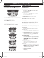
5.7 TARGET HR
5.8 CONSTANT WATTS
The A3x has digital contact and wireless heart rate monitoring capabilities
as standard equipment.
Resistance level is set by the user and constantly changes to reflect stride
speed. As stride speed (SPM) increases, resistance decreases while output
wattage stays the same. In turn, if stride speed decreases then resistance
increases.
• To use heart rate monitor, locate the metal sensors located on the fixed handlebars.
HR Contact Sensor
STEP 1: Select WATTS by using the UP or DOWN arrow keys.
Press SELECT or wait 5 seconds.
Selecting START will start program.
STEP 2: Select TIME by using the UP or DOWN arrow keys.
Press SELECT or wait 5 seconds.
Selecting START will start program.
STEP 3: Select WEIGHT by using the UP or DOWN arrow keys.
Press START or SELECT to begin workout.
Display, Starting 3, Starting 2, Starting 1.
Hold the grips for a minimum of 10 seconds. Your heart rate (or HR) will
display in the lower right hand corner of the alphanumeric LED.
Follow these easy steps to enter into the Heart Rate Program.
STEP 1: Select the TARGET HR button.
Press SELECT or wait 5 seconds.
Selecting START will start program.
STEP 2: Select AGE by using the UP or DOWN arrow keys.
Press SELECT or wait 5 seconds.
Selecting START will start program.
STEP 3: Select PRECENT by using the UP or DOWN arrow keys.
Press SELECT or wait 5 seconds.
Selecting START will start program.
STEP 4: Select TIME by using the UP or DOWN arrow keys.
Press SELECT or wait 5 seconds.
Selecting START will start program.
STEP 5: Select WEIGHT by using the UP or DOWN arrow keys.
Press START or SELECT to begin workout.
Display, Starting 3, Starting 2, Starting 1.
Heart rate protocols.
• HR is within 10 BPM (beats per minute) of target, upper LED display will
show a heart.
• HR is a greater or less than 10 BPM of target, resistance level will increase or
decrease every 10 seconds.
• HR is greater than 14 BPM of target, resistance level will drop to 30%.
• HR is greater than 10 BPM of target, lower LED will display:
“WARNING HR ABOVE TARGET
• HR is greater than 20 BPM, program immediately ends.
11
A3x_E3xc_rev1.7.indd 11
8/6/10 2:34 PM
CHAPTER 6: Programming & Engineering Mode
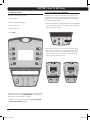
6.1 USING MANAGER MODE
6.2 MANAGER SCREEN DESCRIPTIONS
• To enter manager mode, hold the UP and DOWN level keys for three
seconds until “MANAGER” appears on the middle LED display.
• P0: Maximum progam time Sets the total run time of any program.
• P1: Default workout time Workout time when QUICK START is pressed or when no time is selected during program set up.
Time
Speed
Distance
Calories
RPM
Watts
Heart Rate
Select screen
Hold to reset
Quick start
start
Elevation
Level
select
Incline
• Press the UP and DOWN elevation keys to scroll between program screens.
• P2: Default resistance level Starting resistance when QUICK START is pressed or no resistance level is selected during program set up.
• P3: Default user weight Weight used for program calorie expenditure calculations.
• P4: Speed Units - Display value in miles or kilometers.
• Press SELECT to modify program setting.
• P5: Machine Type The Console is shared on the A3x. A3x default setting is “SWING”.
• Press UP or DOWN level keys to change value.
• Press QUICK START to save setting.
• P6: Console beep on / off - Confirmation beeps can be turned on or off.
• Press QUICK START again to exit manager mode.
(example changing default time from 20:00 - 30:00 minutes).
• P7: Accumulated distance - Total distance of all programs.
• P8: Accumulated time - Total accumulated program time displayed in hours.
Time
Speed
Distance
Calories
RPM
Watts
Level
Heart Rate
Select screen
Hold to reset
Quick start
start
Elevation
Incline
select
Start pedaling to view operating instructions
Speed
Distance
RPM
Watts
Select screen
Hold to reset
Quick start
start
Time
Level
Speed
Calories
RPM
Incline
Level
Watts
Elevation
Heart Rate
Select screen
Hold to reset
Incline
Time
Speed
Distance
Calories
RPM
Watts
select
Elevation
Heart Rate
Select screen
Hold to reset
Quick start
start
select
Distance
Quick start
start
Elevation
Heart Rate
Level
Time
Calories
Incline
select
• P9: Display language Select between English, Spanish, French Italian, Dutch and German.
• P10: Software version Current version of software. Refer to this when calling Matrix Technical Service.
• P11: Incline calibration (A3x only) Default display is OFF. Selecting ON will automatically calibrate the
incline motor (s) to factory settings. Use this feature when actual
elevation does not match console display.
• P12: Incline Reset (A3x only) This is a software feature that resets machine elevation to 0 degrees
after 30 seconds of user inactivity. During incline reset, movement can be stopped by pressing any console key. Display will scroll “HOLD
SELECT TO RESUME”. To resume reset to 0 degrees, hold “SELECT”key for three seconds. • P13: Default incline level (A3x only) Starting incline level at each program start except FIT TEST. Factory setting is 10%. In FIT TEST, elevation is set to 0%.
• P14: Error Code Console will record up to three errors. Error codes are stored permanently unless reset by a technician. To reset error codes, hold MANUAL and
RANDOM keys for three seconds. Refer to these error codes when
calling Matrix technical service for assistance.
• P15: LCB Version Display will show LCB.VER XX YYY. XX is machine type.
YYY is version number.
12
A3x_E3xc_rev1.7.indd 12
8/6/10 2:34 PM
CHAPTER 6: Programming & Engineering Mode
CODE: INFORMATION
DEFAULT
MIN
MAX
P0: Maximum progam time -
95 min
10
95
P1: Default workout time -
P2: Default resistance level -
P3: Default user weight - P4: Speed units -
20 min
10
MAX
1
1
25
80
400
P5: Machine Type - P6: Console beep on / off -
Swing Ramp
0
100
150 lbs. /75 kg
mi
on
P7: Accumulated distance P8: Accumulated time P9: Display language -
P10: Software version P11: Incline calibration P12: Incline reset - P13: Default incline level -
P14: Error Code -
English
on
10
NOTE: DEFAULT TIME will update to the same as MAX TIME if MAX TIME is less
than DEFAULT TIME.
13
A3x_E3xc_rev1.7.indd 13
8/6/10 2:34 PM
CHAPTER 7: Moving The Unit
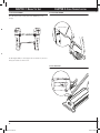
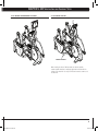
7.1 A3x ASCENT TRAINER
CHAPTER 8: Serial Number Location
8.1 A3x ASCENT TRAINER
A3x - Two hand holds are located just above the MATRIX logo on the rear legs. SERIAL # PLACEMENT
LIFT HANDLES
The A3x weights 390lbs. To avoid injury to the user and the unit, be sure to
have proper assistance to move the unit.
8.2 E3xc ELLIPTICAL
SERIAL #
PLACEMENT
14
A3x_E3xc_rev1.7.indd 14
8/6/10 2:34 PM
CHAPTER 9: A3X Specifications
and
Assembly Steps
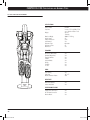
9.1 A3x ASCENT TRAINER SPECIFICATIONS
A3x-01
PRODUCT NAME
USER INTERFACE
STRIDE LENGTH
21 - 24”
INCLINE RANGE
30˚
CONSTANT RATE OF ACCELERATION
YES
CONTACT HEART RATE SENSORS
YES
TELEMETRIC HEART RATE RECEIVER
YES
A3X • ASCENT
REPLACEABLE FOOTPEDAL INSERTS
YES
3.75”
Q-FACTOR
MUTLI-POSITION DUAL ACTION
AND ERGO-BEND STATIONARY
HANDLE BAR DESIGN
RESISTANCE SYSTEM
JID HYBRID ECB
TECHNOLOGY
120v - 220v
POWER REQUIREMENTS
MINIMUM WATTS
15
MAXIMUM WATTS
600
CONSOLE
DISPLAY TYPE
LED
DISPLAY FEEDBACK
INCLINE, TIME, SPEED, DISTANCE, CALORIES,
WATTS, LEVEL, HEARTRATE, RPM
PROGRAMS
HEART RATE, CONSTANT WATTS, MANUAL,
RANDOM, INTERVAL, FAT BURN, ROLLING HILLS
RESISTANCE LEVELS
25
ELEVATION LEVELS
20
ONE-BUTTON QUICK START
YES
CSAFE
YES
PAUSE TIME
30 SECONDS
ON-THE-FLY PROGRAM CHANGE
YES
FULL COURSE SCREEN VIEW
YES
ENTERTAINMENT
FITCONNEXXION™ OPTION
TECHNICAL SPECIFICATIONS
OVERALL DIMENSIONS
80”L x 34.5”W x 72”H
MAXIMUM USER WEIGHT
400 LBS
WEIGHT
390 LBS
SHIPPING WEIGHT
434 LBS
TRANSPORT WHEEL
YES
15
A3x_E3xc_rev1.7.indd 15
8/6/10 2:34 PM
CHAPTER 9: A3x Specifications
and
Assembly Steps
A3X • ASCENT
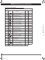
9.2 A3x ASCENT TRAINER FASTENERS
QTY
PART #
SKETCH
DESCRIPTION
HARDWEAR BAG
04
Z01
HEX SOCKET HEAD CAP (M8 x 15L)
YELLOW
08
Z02
HEX SOCKET HEAD CAP (M8 x 20L)
BLACK
06
Z03
CROSS TRUSS HEAD (M5 x 10L)
WHITE
04
Z04
HEX SOCKET HEAD CAP (M8 x 65L)
WHITE
02
Z05
HEX SOCKET HEAD CAP (M8 x 55L)
WHITE
02
Z06
FLAT WASHER (8.2 x 16.0 x 1.0T)
WHITE
02
Z07
NYLON NUT (M8 x 1.25P)
WHITE
04
Z08
AXLE
WHITE
02
Z34
HEX SOCKET HEAD CAP (M8 x 25L)
BLUE
04
N51
CROSS TRUSS HEAD (M5 x 8L)
Included in console
16
A3x_E3xc_rev1.7.indd 16
8/6/10 2:34 PM
CHAPTER 9: A3X Specifications
and
Assembly Steps
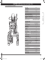
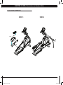
9.3 A3x ASCENT TRAINER ASSEMBLY STEPS
STEP 2
STEP 1
3020
8
3020
8
Z04 x4
Z02 x8
Z03 x6
Z01 x4
Z08 x4
Z06
Z07
Z05
Lightly grease
17
A3x_E3xc_rev1.7.indd 17
8/6/10 2:34 PM
CHAPTER 9: A3X Specifications
and
Assembly Steps
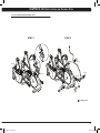
9.3 A3x ASCENT TRAINER ASSEMBLY STEPS
FINAL ASSEMBLY
STEP 3
3020
8
N51 x4
3020
8
Z34
Water Bottle
Holder
18
A3x_E3xc_rev1.7.indd 18
8/6/10 2:34 PM
CHAPTER 9: A3X Specifications
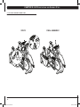
9.4 A3x OPTIONAL ENTERTAINMENT ACCESSORY
and
Assembly Steps
9.5 A3x LEVELING THE UNIT
MIDDLE LEVELERS
When leveling the Ascent Trainer, make sure that the middle levelers (shown above) are completely tightened and flush with the bottom of the machine. Use only the front two levelers to balance out
the machine.
19
A3x_E3xc_rev1.7.indd 19
8/6/10 2:34 PM
CHAPTER 10: E3Xc Specifications
and
Assembly Steps
10.1 E3xc ELLIPTICAL SPECIFICATIONS
SPECIFICATIONS
Product Name
Foot Print
Weight
Max User Weight
Stride Length
Frame Construction
Self-Powered
Resistance Type
Resistance Levels
Dual Action
E3xc-01
inches = 75”L x 29”W x 71”H
cm = 182.9 x 215.9 x 73.6
281 lbs
158.8 kg
400 lbs = 181 kg
21”
Steel
Yes
Generator
25
Yes
PROGRAMS
One Button Quick Start
Random (20 profiles)
Target Heart Rate
Interval
Constant Watts
Rolling
Fat Burn
Fit Test
Yes
Yes
Yes
Yes
Yes
Yes
Yes
Yes
PEDAL
Self Leveling
Pedal Size
Distance Between Pedals
Yes
16” x 7”
3.0”
HEART RATE
Wireless Heart Rate
Contact Heat Rate
Yes
Yes
ENTERTAINMENT READY
Coaxial Cable Connection
AC TV Power Connection
Monitor Mount
Yes
Yes
Yes
20
A3x_E3xc_rev1.7.indd 20
8/6/10 2:34 PM
CHAPTER 10: E3Xc Specifications
and
Assembly Steps
10.2 E3xc ELLIPTICAL TRAINER FASTENERS
FASTENERS
REFERENCE
SKETCH
DESCRIPTION
QUANTITY PACKAGE COLOR
SOCKET HEAD CAP SCREW(M8x20L)
8
PINK
Z32
WASHER(Ø8.4xØ15.5x1.6t)
8
PINK
Z13
SOCKET HEAD CAP SCREW(M10x15L)
2
RED
Z03
BUTTON HEAD MACHINE SCREW(M5x10L)
4
WHITE
Z14
SOCKET HEAD CAP SCREW(M8x20L)
2
RED
Z01
SOCKET HEAD CAP SCREW(M8x15L)
8
GREEN
Z34
SOCKET HEAD CAP SCREW(M8x25L)
2
BLUE
Z01
SOCKET HEAD CAP SCREW(M8x15L)
6
ORANGE
Z02
WAVE WASHER(Ø20.5xØ29x1.5t)
2
ORANGE
Z08
WAVE WASHER(Ø20.7xØ29.1x0.3t)
2
ORANGE
Z09
FLAT HEAD SOCKET SCREW(M5x12L)
8
BLACK
E42
CONNECT PLATE
2
ORANGE
Z03
SOCKET HEAD CAP SCREW(M5x10L)
6
YELLOW
Z05
SOCKET HEAD CAP SCREW(M8x55L)
2
YELLOW
Z06
WASHER(Ø8.2xØ16x1.0t)
2
YELLOW
Z07
NYLON NUT(M8x1.25P)
2
YELLOW
Z30
AXLE
4
YELLOW
Z04
SOCKET HEAD CAP SCREW(M8x65L)
4
YELLOW
Z51
BUTTON HEAD MACHINE SCREW(M5x8L)
4
E3XC • ELLIPTICAL
Z31
21
A3x_E3xc_rev1.7.indd 21
8/6/10 2:34 PM
CHAPTER 10: E3Xc Specifications
and
Assembly Steps
10.3 E3xc ELLIPTICAL ASSEMBLY STEPS
STEP 2
STEP 1
INSERT
RUBBER
BOOT
BEFORE
ATTACHING
MAST PLATE
1) TIE BOTTOM
WIRES TO
WHITE TWIST
TIE IN MAST
E3XC • ELLIPTICAL
Z01
2) PULL UP
WIRES TO
CONSOLE
INCLUDED
WITH CONSOLE
N51x4
1) CONNECT WIRES
2) INSERT BATTERY
Z32x8
Z31x8
Z03x4
Z13x2
Z14x2
22
A3x_E3xc_rev1.7.indd 22
8/6/10 2:34 PM
CHAPTER 10: E3Xc Specifications
and
Assembly Steps
10.3 E3xc ELLIPTICAL ASSEMBLY STEPS
STEP 3
STEP 4
Z09
Z04
Z08
Z02
E42
Z01
23
A3x_E3xc_rev1.7.indd 23
8/6/10 2:34 PM
CHAPTER 10: E3Xc Specifications
and
Assembly Steps
10.3 E3xc ELLIPTICAL ASSEMBLY STEPS
FINAL ASSEMBLY
STEP 5
Z34
Water Bottle
Holder
Z03
Z07
Z06
Z30
Z05 Z03
REMOVE PLASTIC
PROTECTION PIECE
FROM INSIDE WHEEL
TRACK
PLASTIC CAP
24
A3x_E3xc_rev1.7.indd 24
8/6/10 2:34 PM
CHAPTER 10: E3Xc Specifications
and
Assembly Steps
10.4 E3xc OPTIONAL ENTERTAINMENT ACCESSORY
25
A3x_E3xc_rev1.7.indd 25
8/6/10 2:34 PM
NOTES:
26
A3x_E3xc_rev1.7.indd 26
8/6/10 2:34 PM
M AT R I X F I T N E S S
1 6 0 0 L A N D M A R K D R I V E C O T TA G E G R O V E W I 5 3 5 2 7 U S A
T O L L F R E E 8 6 6 . 6 9 3 . 4 8 6 3 w w w. m a t r i x f i t n e s s . c o m FA X 6 0 8 . 8 3 9 . 8 6 8 7
PA RT # 0 0 0 0 0 9 2 4 1 1
REV. 1.7
A3x_E3xc_rev1.7.indd 27
8/6/10 2:34 PM