1
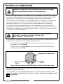
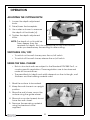
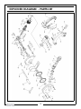
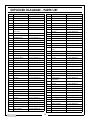
WALL CHASER
MODEL NO: CON1450WC
PART NO: 6462165
OPERATION & MAINTENANCE
INSTRUCTIONS
LS0109
INTRODUCTION
Thank you for purchasing this CLARKE Wall Chaser.
Before attempting to use this product, please read this manual thoroughly and
follow the instructions carefully. In doing so you will ensure the safety of yourself
and that of others around you, and you can look forward to your purchase
giving you long and satisfactory service.
GUARANTEE
This product is guaranteed against faulty manufacture for a period of 12
months from the date of purchase. Please keep your receipt which will be
required as proof of purchase.
This guarantee is invalid if the product is found to have been abused or
tampered with in any way, or not used for the purpose for which it was
intended.
Faulty goods should be returned to their place of purchase, no product can
be returned to us without prior permission.
This guarantee does not effect your statutory rights.
2
GENERAL SAFETY RULES
WARNING: READ ALL INSTRUCTIONS. FAILURE TO FOLLOW ALL
INSTRUCTIONS LISTED BELOW MAY RESULT IN ELECTRIC SHOCK, FIRE AND/
OR SERIOUS INJURY. SAVE THESE INSTRUCTIONS.
WORK AREA
1.
Keep work area clean and well lit. Cluttered and dark areas invite accidents.
2.
Do not operate power tools in explosive atmospheres, such as in the presence of flammable
liquids, gases or dust. Power tools create sparks which may ignite the dust or fumes.
3.
Keep children and bystanders away while operating a power tool. Distractions can cause you to
lose control.
ELECTRICAL SAFETY
1.
Power tool plugs must match the outlet. Never modify the plug in any way. Do not use any
adapter plugs with earthed (grounded) power tools. Unmodified plugs and matching outlets will
reduce risk of electric shock.
2.
Avoid body contact with earthed or grounded surfaces such as pipes, radiators, ranges and
refrigerators. There is an increased risk of electric shock if your body is earthed or grounded.
3.
Do not expose power tools to rain or wet conditions. Water entering a power tool will increase
the risk of electric shock.
4.
Do not abuse the cord. Never use the cord for carrying, pulling or unplugging the power tool.
Keep cord away from heat, oil, sharp edges or moving parts. Damaged or entangled cords
increase the risk of electric shock.
5.
When operating a power tool outdoors, use an extension cord suitable for outdoor use. Use of a
cord suitable for outdoor use reduces the risk of electric shock.
PERSONAL SAFETY
1.
Stay alert, watch what you are doing and use common sense when operating a power tool. Do
not use a power tool while you are tired or under the influence of drugs, alcohol or medication. A
moment of inattention while operating power tools may result in serious personal injury.
2.
Use safety equipment. Always wear eye protection. Safety equipment such as dust mask, nonskid safety shoes, hard hat, or hearing protection used for appropriate conditions will reduce
personal injuries.
3.
Avoid accidental starting. Ensure the switch is in the off position before plugging in. Carrying
power tools with your finger on the switch or plugging in power tools that have the switch on
invites accidents.
4.
Remove any adjusting key or wrench before turning the power tool on. A wrench or a key left
attached to a rotating part of the power tool may result in personal injury.
5.
Do not overreach. Keep proper footing and balance at all times. This enables better control of
the power tool in unexpected situations.
6.
Dress properly. Do not wear loose clothing or jewellery. Keep your hair, clothing and gloves
away from moving parts. Loose clothes, jewellery or long hair can be caught in moving parts.
7.
If devices are provided for the connection of dust extraction and collection facilities, ensure
these are connected and properly used. Use of these devices can reduce dust related hazards.
3
POWER TOOL USE AND CARE
1.
Do not force the power tool. Use the correct power tool for your application. The correct power
tool will do the job better and safer at the rate for which it was designed.
2.
Do not use the power tool if the switch does not turn it on and off. Any power tool that cannot be
controlled with the switch is dangerous and must be repaired.
3.
Disconnect the plug from the power source before making any adjustments, changing
accessories, or storing power tools. Such preventative safety measures reduce the risk of starting
the power tool accidentally.
4.
Store idle power tools out of the reach of children and do not allow persons unfamiliar with the
power tool or these instructions to operate the power tool. Power tools are dangerous in the
hands of untrained users.
5.
Maintain power tools. Check for misalignment or binding of moving parts, breakage of parts and
any other condition that may affect the power tools operation. If damaged, have the power tool
repaired before use. Many accidents are caused by poorly maintained power tools.
6.
Keep cutting tools sharp and clean. Properly maintained cutting tools with sharp cutting edges
are less likely to bind and are easier to control.
7.
Use the power tool, accessories and tool bits etc., in accordance with these instructions and in
the manner intended for the particular type of power tool, taking into account the working
conditions and the work to be performed. Use of the power tool for operations different from
those intended could result in a hazardous situation.
SERVICE
1.
Have your power tool serviced by a qualified repair person using only identical replacement
parts. This will ensure that the safety of the power tool is maintained.
ADDITIONAL SAFETY RULES FOR WALL CHASERS
1.
Always use guard provided with the tool. The guard must be securely attached to the power tool
and positioned for maximum safety, so the least amount of wheel is exposed towards the
operator. Position yourself and bystanders away from the plane of the rotating wheel. The guard
helps to protect operator from broken wheel fragments and accidental contact with wheel.
2.
The rated speed of the cutting discs must be at least equal to the maximum speed marked on
the power tool. Cutting discs running faster than their rated speed can break and fly apart.
3.
Cutting discs must be used only for recommended applications. Side forces applied to these
discs may cause them to shatter.
4.
The arbor size of the cutting discs and flanges must properly fit the spindle of the power tool. Discs
and flanges with arbor holes that do not match the mounting hardware of the power tool will run
out of balance, vibrate excessively and may cause loss of control.
5.
Do not use damaged cutting discs. Before each use, inspect the discs for chips and cracks. If
power tool or wheel is dropped, inspect for damage or install an undamaged disc. After
inspecting and installing the disc, position yourself and bystanders away from the plane of the
cutting disc and run the power tool at maximum no load speed for one minute.
6.
Hold the power tool only by the insulated gripping surfaces when performing an operation where
the cutting tool may contact hidden wiring or its own cord. Contact with a “live” wire will also
make exposed metal parts of the power tool “live” and shock the operator.
7.
Position the cord clear of the cutting discs. If you lose control of the power tool, the cord may be
cut or snagged and your hand or arm may be pulled into the cutting disc.
8.
Never lay the power tool down until the cutting discs have come to a complete stop. The cutting
discs may grab the surface and pull the power tool out of your control.
9.
Do not run the power tool while carrying it at your side. Accidental contact with the cutting disc
could snag your clothing, pulling the accessory into your body.
4
KICKBACK AND RELATED WARNINGS
Kickback is a sudden reaction to a pinched or snagged cutting disc. Pinching or
snagging causes rapid stalling of the rotating wheel which in turn causes the
uncontrolled power tool to be forced in the opposite direction of the wheels rotation.
1.
Maintain a firm grip on the power tool and position your body and arm to allow you to
resist kickback forces. Always use auxiliary handle, if provided, for maximum control over
kickback or torque reaction during start-up. The operator can control torque reactions or
kickback forces, if proper precautions are taken. Never place your hand near the cutting
disc. The wall chaser may kickback over your hand.
2.
Do not position your body in the area where the power tool will move if kickback occurs.
Kickback will propel the tool in the direction opposite to the wheel’s movement at the
point of snagging.
3.
Use special care when working corners, sharp edges, etc. Avoid bouncing and snagging
the accessory. Corners, sharp edges or bouncing have a tendency to snag the rotating
accessory and cause loss of control or kickback.
4.
Do not attach a saw chain woodcarving blade or toothed saw blade. Such blades create
frequent kickback and loss of control over the power tool.
5.
Do not “jam” the cut-off wheel or apply excessive pressure. Do not attempt to make an
excessive depth of cut. Overstressing the wheel increases the loading and susceptibility to
twisting or binding of the wheel in the cut and the possibility of kickback or wheel
breakage.
6.
When wheel is binding or when interrupting a cut for any reason, switch off the power tool
and hold the power tool motionless until the wheel comes to a complete stop. Never
attempt to remove the cut-off wheel from the cut while the wheel is in motion, otherwise
kickback may occur. Investigate and take corrective action to eliminate the cause of
wheel binding.
7.
Do not restart the cutting operation in the workpiece. Let the wheel reach full speed and
carefully re-enter the cut. The wheel may bind, walk up or kickback if the power tool is
restarted in the workpiece.
8.
Use extra caution when making a “pocket cut” into existing walls or other blind areas. The
protruding wheel may cut gas or water pipes, electrical wiring or objects that can cause
kickback.
5
ELECTRICAL CONNECTIONS
WARNING! Read these electrical safety instructions thoroughly
before connecting the product to the mains supply.
Before switching the product on, make sure that the voltage of your electricity supply is
the same as that indicated on the rating plate. This product is designed to operate on
230VAC 50Hz. Connecting it to any other power source may cause damage.
This product may be fitted with a non-rewireable plug. If it is necessary to change the
fuse in the plug, the fuse cover must be refitted. If the fuse cover becomes lost or
damaged, the plug must not be used until a suitable replacement is obtained.
If the plug has to be changed because it is not suitable for your socket, or due to
damage, it should be cut off and a replacement fitted, following the wiring instructions
shown below. The old plug must be disposed of safely, as insertion into a mains socket
could cause an electrical hazard.
WARNING! The wires in the power cable of this product are
coloured in accordance with the following code:
Blue = Neutral
Brown = Live
If the colours of the wires in the power cable of this product do not correspond with the
markings on the terminals of your plug, proceed as follows.
• The wire which is coloured Blue must be connected to the terminal which is
marked N or coloured Black.
• The wire which is coloured Brown must be connected to the terminal which is
marked L or coloured Red.
Plug must be BS1363/A approved.
Always fit a 13 Amp fuse.
Live
Neutral
(Brown)
(Blue)
Ensure that the outer sheath of the cable is firmly held by the clamp
We strongly recommend that this machine is connected to the mains supply via a
Residual Current Device (RCD)
If in any doubt, consult a qualified electrician. DO NOT attempt any repairs yourself.
This symbol indicates that this is a Class II product, and does not require an earth
connection.
6
BEFORE USE
WHAT’S SUPPLIED
Unpack your wall chaser and make sure that the following items are present.
Should there be any damage caused during transit contact your Clarke
dealer immediately.
• 1 x Wall Chaser
• 1 x Pin Spanner
• 1 x Attachable Handle
• 1 x Breakout Chisel
• 1 x 5mm Hex Key
• 1 x Dust Extraction Attachment
• 2 x Cutting Discs (150mm Diameter x 22.2mm Bore)
SPINDLE LOCK BUTTON.
When mounting or changing the
cutting discs, the spindle lock button
prevents the spindle from turning
when you unscrew and remove the
outer flange (using the Pin Spanner
provided).
Spindle lock button
WARNING: NEVER PRESS THE SPINDLE LOCK BUTTON WHEN THE UNIT IS
RUNNING.
7
REPLACING THE CUTTING DISCS
WARNING: Disconnect the plug from the power source before making
any adjustments or changing accessories.
NOTE: Always replace both discs at the same time.
1. Remove the depth adjustment
knob by hand and 3 bolts
indicated using the 5mm hex key
supplied.
2. Lift off the side plate.
Side plate
3. Press and hold the spindle lock
button.
4. Use the Pin Spanner supplied to
release the outer flange
SETTING THE CUTTING WIDTH
The cutting width is determined by
the number of spacer discs you put in
between the discs.
• The cutting width is equal to:
The thickness of the 2 blades (2
x 2.5 mm) + the thickness of the
spacers.
• Make sure that the inner flange
is seated properly and the flat
section has engaged with the
flat part at the base of the spindle.
NOTE: All spacers must be used to prevent the blades from wobbling.
simply place the spacers on the outside of the cutting discs to
make the cutting width narrower.
5. Replace the side plate and secure with the depth adjustment knob and 3
bolts you removed in step 1.
8
FITTING THE DUST EXTRACTION ASSEMBLY
Attach the dust extraction assembly
to the wall chaser.
• Insert the assembly (1) into the
extraction port (2) and rotate
slightly clockwise to lock into
place.
• Remove the collar (4) and slide
it over the vacuum cleaner
hose.
• Push the hose onto the dust
extraction tube (3).
• Secure in place by tightening up the collar (4).
FITTING THE ATTACHABLE HANDLE
Screw the handle (5) into the hole (6)
shown on the wall chaser.
9
OPERATION
ADJUSTING THE CUTTING DEPTH
1. Loosen the depth adjustment
knob.
2. Raise/lower the baseplate.
3. Use a ruler as shown to measure
the depth of the blade (d).
4. Tighten the depth adjustment
knob.
NOTE: The depth of cut should be
3mm deeper than the
required slot depth, this is to compensate for any inaccuracies
when you break away the resulting fin after cutting.
SWITCHING ON / OFF
• To switch on the wall chaser, press the on/off switch
• To switch off the wall chaser, release the on/off switch
USING THE WALL CHASER
• Slots in structural walls are subject to the Standard DIN1053 Part1, or
country-specific regulations. These regulations are to be observed
under all circumstances.
• The permitted slot depth and width depends on the slot length, wall
thickness and the building material used.
1. Mark the surface to be worked.
2. Keep the wall chaser in an upright
position.
3. Move the wall chaser across the
surface using the guide wheel.
4. Move at a constant speed, do not
force the wall chaser.
5. Remove the remaining material
using the breakout chisel
supplied.
10
MAINTENANCE
WARNING: MAKE SURE THAT THE WALL CHASER IS SWITCHED OFF AND
DISCONNECTED FROM THE MAINS SUPPLY BEFORE STARTING ANY
CLEANING OR MAINTENANCE PROCEDURES.
With the exception of changing the blade there are no user serviceable parts in
this unit.
After use,
• Clean away any accumulated dust.
• Check the condition of the cutting disc for signs of cracking, and
discard immediately if apparent.
• Keep the cooling vents clear.
• Clean the housing with a soft cloth. Any worn or damaged parts
should be replaced by qualified personnel.
• Refer to qualified service personnel if internal maintenance is
required. Always store in the carrying case supplied.
11
SPECIFICATIONS
CON1450WC
Electrical Supply
230V @ 50Hz
Power Rating
1450W
Part Number
6462165
Disc Bore
22.2 mm
Disc Diameter
150 mm
Disc Thickness
2.5 mm
Cutting Depth
8-40 mm
Cutting Width
8-30 mm
Guaranteed Sound Power dB LWa
106.9 dB
Vibration
<2.5m/s2
Protection Class
II
Dimensions (L x W x H)
430 x 190 x 250 mm
Weight
5 Kg
PARTS AND SERVICING
For Parts & Servicing, please contact your nearest dealer, or
CLARKE International, on one of the following numbers
PARTS & SERVICE TEL: 020 8988 7400
PARTS & SERVICE FAX: 020 8558 3622
or e-mail as follows:
PARTS: [email protected]
SERVICE: [email protected]
12
EXPLODED DIAGRAM - PARTS LIST
13
EXPLODED DIAGRAM - PARTS LIST
NO
DESCRIPTION
PART NO
NO
DESCRIPTION
PART NO
1
Dust extraction
CON1450WC01
43
Roll sheath
CON1450WC43
2
Rubber ring
CON1450WC02
44
Washer
CON1450WC44
3
Pree ring
CON1450WC03
45
Shaft
CON1450WC45
4
Bend tube
CON1450WC04
46
Circlip
CON1450WC46
5
Sealed ring
CON1450WC05
47
Washer
CON1450WC47
6
Connect tube
CON1450WC06
48
Pinion gear
CON1450WC48
7
Aluminium
connect
CON1450WC07
49
Bearing
CON1450WC49
50
Screw
CON1450WC50
8
Screw
CON1450WC08
51
Bearing cord
CON1450WC51
9
Washer
CON1450WC09
52
Woodruff key
CON1450WC52
10
Rubber ring
CON1450WC10
53
Rotor
CON1450WC53
11
Screw
CON1450WC11
54
Screw
CON1450WC54
12
Washer
CON1450WC12
55
Stator
CON1450WC55
13
Knob
CON1450WC13
56
Bearing
CON1450WC56
14
Screw
CON1450WC14
57
CON1450WC57
15
Spring Washer
CON1450WC15
Inductive magnet
ring
16
Washer
CON1450WC16
58
Bearing cover
CON1450WC58
17
Out guard
CON1450WC17
59
Stator housing
CON1450WC59
18
Out flange
CON1450WC18
60
Brush holder
CON1450WC60
19
Cutting disc
CON1450WC19
61
Screw
CON1450WC61
20
Distance washer
CON1450WC20
62
Brush
CON1450WC62
21
Flange
CON1450WC21
63
Brush cap
CON1450WC63
22
Depth adjustment
CON1450WC22
64
Screw
CON1450WC64
23
Screw
CON1450WC23
65
Switch
CON1450WC65
24
Inner guard
CON1450WC24
66
Washer
CON1450WC66
25
Nip cover
CON1450WC25
67
Screw
CON1450WC67
26
Output shaft
CON1450WC26
68
Right rear cover
CON1450WC68
27
Woodruff key
CON1450WC27
69
Capacitor
CON1450WC69
28
Screw
CON1450WC28
70
CON1450WC70
29
Front cap
CON1450WC29
Electronics
regulator
30
Felt
CON1450WC30
71
Screw
CON1450WC71
Screw
CON1450WC72
31
Bearing
CON1450WC31
72
32
Circlip
CON1450WC32
73
Spring Washer
CON1450WC73
33
Large gear
CON1450WC33
74
Washer
CON1450WC74
CON1450WC34
75
Screw
CON1450WC75
Cord anchorage
CON1450WC76
34
Circlip
35
bearing
CON1450WC35
76
36
Gear box
CON1450WC36
77
Left rear cover
CON1450WC77
37
Screw
CON1450WC37
78
Cord guard
CON1450WC78
CON1450WC38
79
Cable
CON1450WC79
Wrench
CON1450WC80
38
Spring
39
Spindle lock
CON1450WC39
80
40
Circlip
CON1450WC40
81
Side handle
CON1450WC81
41
Screw
CON1450WC41
82
Chisel
CON1450WC82
CON1450WC42
83
Hex key
CON1450WC83
84
Wind guard
CON1450WC84
42
Roll wheel
14
DECLARATION OF CONFORMITY
15