1
V
®
m
lar
leA
Te
NurseCall Main Unit
User Manual
all
rseC
Nu
NurseCall Main Unit
| en
3
Table of Contents
1
Identification
7
1.1
Document
7
1.2
Customer support addresses
8
2
Generalities
9
2.1
Document
9
2.2
NurseCall System
9
2.3
NurseCall Main Unit
9
3
Safety Instructions
11
3.1
Chapter overview
11
3.2
Introduction
11
3.2.1
Principle
11
3.2.2
Importance of safety instructions
11
3.2.3
Disregarding safety rules
11
3.3
Environmental conditions
12
3.4
General safety instructions
13
3.4.1
Observation and information
14
3.5
Special safety instructions
14
4
Description
15
4.1
General description
15
4.1.1
Top view
15
4.1.2
Bottom view
16
4.1.3
Front view
17
4.1.4
Rear view
17
4.2
Detailed description
18
4.2.1
Loudspeaker
18
4.2.2
Display
18
4.2.3
Keyboard
18
4.2.4
Identification label
20
4.2.5
RS-232 interface
21
4.2.6
RS-485 interface
23
4.2.7
Antenna
23
5
Transport
25
5.1
Transportation
25
5.1.1
Domestic
25
5.1.2
International and overseas
25
5.2
Transportation data
25
5.2.1
Box dimensions
25
TeleAlarm SA®
User Manual
953.92 | v1.0 | 2007.07
4
en |
NurseCall Main Unit
6
Installation
27
6.1
Unpacking
27
6.1.1
List of contents
27
6.2
Installation
28
6.2.1
Generalities
28
6.2.2
Installation on a piece of furniture
28
6.2.3
Wall installation
28
6.2.4
Installing the antenna
29
6.2.5
Connecting to the mains
30
6.2.6
Connecting the RS-232
31
6.2.7
Setting the jumpers on RS-232 board
32
6.2.8
Connecting the RS-485
33
6.2.9
Setting the 100 Ohm termination jumper
34
7
Programming
35
7.1
Generalities
35
7.1.1
Programming with keyboard
35
7.1.2
Programming with NPS software
36
7.1.3
Exiting the programming mode and cancelling entries
36
7.1.4
Key not allowed
36
7.2
First use
37
7.2.1
List of original factory settings
37
7.2.2
Language
38
7.2.3
Localization Mode
38
7.2.4
Display Mode
38
7.3
Parameters
39
7.3.1
Diagrams
39
7.3.2
Access to parameters
44
7.3.3
List of parameters
44
7.3.4
Programming the interface language
45
7.3.5
Date and time setting
45
7.3.6
RS-232 output setting
46
7.3.7
Local Acknowledgement setting
50
7.3.8
Output relay setting
50
7.4
Special settings
51
7.4.1
Displaying firmware version
51
7.4.2
Resetting all parameters (including date and time)
51
7.4.3
Assistance and fire priority
52
7.4.4
Assistance and fire non priority
52
7.4.5
Special texts in German
52
7.4.6
Standard texts in German
52
7.4.7
Standard NurseCall selection
53
7.4.8
Universal NurseCall selection
53
7.4.9
Maximum number of Alarm Transmitters (toggle)
54
7.4.10
Maximum number of Acknowledgement Transmitters (toggle)
55
7.4.11
Maximum number of Events buffered (toggle)
55
7.4.12
Daily message setting (toggle)
55
7.4.13
RS232 message setting (toggle)
55
953.92 | v1.0 | 2007.07
User Manual
TeleAlarm SA®
NurseCall Main Unit
| en
5
7.5
Transmitters
56
7.5.1
Generalities
56
7.5.2
Alarm Transmitter programming
56
7.5.3
Alarm Transmitter checking
57
7.5.4
Alarm Transmitter erasing
58
7.5.5
Acknowledgement Transmitter programming
59
7.5.6
Acknowledgement Transmitter checking
59
7.5.7
Acknowledgment Transmitter erasing
60
7.5.8
Erasing all Acknowledgement Transmitters
60
8
Operating Instructions
61
8.1
Loudspeaker volume adjusting
61
8.2
Alarm- or Event Buffer consulting
61
8.2.1
Switching between Alarm and Event Buffers indication
62
8.2.2
Display indications
63
8.2.3
Local Acknowledgement
64
9
Troubleshooting
65
9.1
"Ack. Transmitter already stored" message
65
9.2
"Radio in use" message
65
9.3
The Green button does not work
65
10
Maintenance
67
10.1
System checking
67
10.2
Power supply monitoring
67
10.3
Backup battery monitoring and checking
67
10.4
Cleaning
68
10.5
Parts replacement
68
10.5.1
Safety instructions
68
10.5.2
Unit Dismantling
68
10.5.3
Backup battery replacing
69
11
Storage
71
11.1
Short term storage
71
11.1.1
Short term storage conditions
71
11.1.2
Long term storage conditions
71
12
Disposal
73
12.1
Disassembly
73
12.2
Local disposal locations
73
12.3
Returning to the manufacturer
73
12.4
Materials
74
12.4.1
Battery
74
TeleAlarm SA®
User Manual
953.92 | v1.0 | 2007.07
6
en |
NurseCall Main Unit
13
Appendix
75
13.1
Electrical specifications
75
13.2
Dimensions and weight
75
13.3
Environmental conditions
75
13.4
List of criteria
76
13.5
Paging systems specifications
78
13.5.1
Multitone RPE670 with ESPA 4.4.4. protocol
78
13.5.2
Multitone RPE670 with MEP protocol
79
13.5.3
DeTeWe protocol
81
13.5.4
Other paging systems
83
13.6
DECT phone system specifications
85
13.6.1
Multitone DECT system CS600 and P318 interface
85
13.7
Connectors
86
13.7.1
LINE socket (unit bottom)
86
13.7.2
Power socket (unit bottom)
86
13.7.3
RS-232 (unit rear)
87
13.7.4
RS-485 (unit rear)
87
13.8
EC-Declaration of conformity
88
14
Glossary
91
953.92 | v1.0 | 2007.07
User Manual
TeleAlarm SA®
NurseCall Main Unit
Identification | en
1
Identification
1.1
Document
Name
No.
User Manual
953.92 |
7
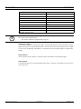
Table 1.1 Document No.
Version
Description
v1.0 | 2007.07
First Edition
Table 1.2 Version Management
TeleAlarm SA®
User Manual
953.92 | v1.0 | 2007.07
8
en | Identification
1.2
NurseCall Main Unit
Customer support addresses
TeleAlarm SA Bosch Group
Bosch Security Systems BV
Unterer Quai 37
Postbus 80002
CH-2502 Biel-Bienne
5600 JB Eindhoven
Switzerland
Nederland
Phone: +41 32 327 25 40
Phone: 0900 8212499
Bosch Security Systems France
Bosch Security Systems nv/sa
Atlantic 361
Torkonjestraat 21F
361, avenue du Général de Gaulle
B-8510 Marke
F-92147 Clamart
Belgium
France
Phone: +32 (0)56 20 02 40
Phone: + 33 (0)825 12 8000
Haus-ServiceRuf
Bosch Security Systems AB
Bosch Sicherheitssysteme GmbH
Kansligatan 10
Ingersheimer Straße 16
SE-602 09 Norrköping
D-70499 Stuttgart
Sweden
Germany
Phone: +46 (0)11 28 04 80
Phone: 01805-47726724
Bosch Security Systems Ltd
Broadwater Park
North Orbital Road
Denham
UB9 5HN
United Kingdom
Phone: 01 895-878093
953.92 | v1.0 | 2007.07
User Manual
TeleAlarm SA®
NurseCall Main Unit
Generalities | en
2
Generalities
2.1
Document
i
2.2
9
NOTICE!
The words written in italic in this document are explained in the glossary.
X
See Section 14 Glossary, page 91.
NurseCall System
Alarms and Messages arriving from NurseCall Transmitters are managed and stored by the
NurseCall Main Unit. This unit is compatible with the NurseCall Master.
i
2.3
NOTICE!
The document "NurseCall General Overview" explains the system concept.
NurseCall Main Unit
Up to 500 Transmitters can be managed by the NurseCall Main Unit.
The basic configuration of the NurseCall Main Unit can handle incoming data as stand-alone
unit (display and acoustic signal).
If the NurseCall Main Unit is connected to optional peripherals using the RS232-Interface, the
information is additionally transmitted to these peripherals. Several other configurations are
available upon request.
i
NOTICE!
RS-232 connection possibilities, see Section 4.2.5 RS-232 interface, page 21.
NurseCall Main Unit can be connected to other Receiver Units, such as a Relay Unit.
i
TeleAlarm SA®
NOTICE!
Connection of several Receiver Units together in one system (Main-Relay configuration), see
Section 4.2.6 RS-485 interface, page 23.
User Manual
953.92 | v1.0 | 2007.07
10
en | Generalities
NurseCall Main Unit
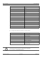
If an Alarm or a Message is received by the unit, following information is displayed and
transmitted to connected peripherals:
–
Identification of Alarm/Message;
–
Floor number / room number / bed number or a single number;
–
Date and time;
–
Quality of received radio signal;
–
Type of storage (Alarm or Event);
–
Identification of the unit receiving the Alarm/Message (Main / Relay).
–
Local position if Localization Mode is selected.
The attribution of a floor number / room number / bed number or a single number to a
Transmitter can be selected (0 to 254). The attribution is programmed in the NurseCall Main
Unit.
i
NOTICE!
Attribution of a floor number / room number / bed number or a single number to a
Transmitter, see Section 7.5 Transmitters, page 56.
The radio receiving range is sufficient with the supplied antenna.
This range depends highly on the distance and the material of your building.
If you wish to improve your radio receiving range, two solutions can be offered:
1.
i
Use of a remote high quality antenna.
NOTICE!
In order to achieve an improvement with other antennas, basic rules have to be fulfilled.
Contact a specialist for correct installation.
2.
Main - Relay connection of several Relay Units.
Further Receiver Units (Relay Units) can be connected using the RS485-Interface.
Maximum bus length: up to 1200 m.
i
NOTICE!
The NurseCall system can be equipped with the optional function Localization. If an Alarm is
received by the unit, the actual position of the Transmitter is shown on the display.
IS76 Beacons with Ferrite Antennas or IS75 Beacons with wire loop should be installed on
doors or corridors in the building to be supervised. When passing one of these modules, the
Transmitter updates its current position. At Alarm triggering, the Transmitter does not only
transmit its identification (who sent the Alarm), but also the position of the last passed
module.
953.92 | v1.0 | 2007.07
User Manual
TeleAlarm SA®
NurseCall Main Unit
3
Safety Instructions | en
11
Safety Instructions
!
3.1
WARNING!
The User / Installer should read and understand this chapter before any intervention on the
NurseCall Main Unit.
Chapter overview
Safety Instructions for a safe and trouble-free operation of the NurseCall Main Unit.
3.2
Introduction
3.2.1
Principle
i
3.2.2
NOTICE!
In case of unclear information, please contact your local representative.
Importance of safety instructions
Each safety and protection instruction in this manual must be adhered to in order to avoid
personnel injuries, property damages or environmental pollution.
In a similar manner, the legal bylaws, the measures in prevention of accidents and for the protection of the environment, as well as the recognised technical rules aiming at appropriate
and safe working conditions which as applied in the country and at the place of use of the NurseCall Main Unit must be adhered to.
3.2.3
Disregarding safety rules
Disregarding the safety rules, as well as existing legal and technical regulations, may lead to
accidents, to property damages or to environmental pollution.
TeleAlarm SA®
User Manual
953.92 | v1.0 | 2007.07
12
en | Safety Instructions
3.3
NurseCall Main Unit
Environmental conditions
WARNING!
The NurseCall Main Unit must not be located near a water tap or any other source of water.
!
The electrical safety of the NurseCall Main Unit is only guaranteed if the electrical installation is
conform to the national reglementation related to medical-use buildings and if this installation
works properly.
The NurseCall Main Unit may not be used in buildings prone to fire and explosion hazards.
CAUTION!
The NurseCall Main Unit may not be stored under exposure to the direct sunlight, to heat, to
dust or to an excessive humidity (only use the equipment in a clean environment).
X
Install the NurseCall Main Unit in a dry place, away from any source of heat.
CAUTION!
Interferences
Avoid immediate proximity to other electric devices such as a television.
953.92 | v1.0 | 2007.07
User Manual
TeleAlarm SA®
NurseCall Main Unit
3.4
Safety Instructions | en
13
General safety instructions
DANGER!
!
Electrocution
During maintenance operations, when the NurseCall Main Unit is powered and its casing is
removed, the NurseCall Main Unit may not be left unattended.
CAUTION!
The NurseCall Main Unit may only be connected to the electrical sources as described in
Section 13.1 Electrical specifications, page 75.
CAUTION!
Maintenance and repairs may only be performed in conformance with the instructions and by
authorized Technical Personnel only.
The sole possession of the User Manual does not allow the personnel to perform any kind of
repair on the NurseCall Main Unit.
Take into account all the warnings and follow all the instructions displayed on the NurseCall
Main Unit and those which are printed in the documentation.
Never try to use replacement pieces other than those authorized by the manufacturer of the
NurseCall Main Unit.
CAUTION!
It is mandatory to use the products specified in the present User Manual to clean the NurseCall Main Unit. If you plan to use another product, only do so after having obtained the authorisation of the manufacturer.
WARNING! Electro Static Discharge
The NurseCall Main Unit contains highly sensitive electronic components. It should be opened
only in an ESD protected environment with respect to the following precautions:
X
Discharge yourself from electrostatic loads by touching a grounded conductive surface
before opening the unit.
X
Avoid touching conductive parts inside the NurseCall Main Unit if not absolutely necessary.
TeleAlarm SA®
User Manual
953.92 | v1.0 | 2007.07
14
en | Safety Instructions
NurseCall Main Unit
CAUTION!
Never let any liquid enter the system. In case of liquid spill inside the NurseCall Main Unit, act
immediately as follows:
i
3.4.1
1.
Switch off the NurseCall Main Unit using the main switch under the casing.
2.
Unplug the power supply adaptor.
3.
Dry up the NurseCall Main Unit.
4.
Clean the NurseCall Main Unit.
5.
Check its electrical functions.
NOTICE!
For further information, please contact your local representative.
Observation and information
In case of defective operation or any other technical incident for which no remedy is
described in this manual, please contact immediately your local representative.
3.5
Special safety instructions
Appropriate safety instructions linked to specific risks are described in the corresponding section of this manual.
953.92 | v1.0 | 2007.07
User Manual
TeleAlarm SA®
NurseCall Main Unit
Description | en
4
Description
4.1
General description
4.1.1
Top view
15
1
2
3
6
5
4
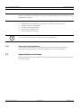
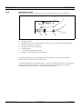
Fig. 4.1 Top view
1.
Loudspeaker (See Section 4.2.1 Loudspeaker, page 18)
2.
Display (See Section 4.2.2 Display, page 18)
3.
Keyboard (under the cover) (See Section 4.2.3 Keyboard, page 18)
4.
Yellow button
Used to view more details about the Event or Alarm currently displayed (Date and time,
position, etc...).
5.
Green button
Used to acknowledge an Alarm locally (See Section 8.2.3 Local Acknowledgement, page 64)
6.
Red button + light
This button is currently not used. The light is blinking red during an Alarm.
TeleAlarm SA®
User Manual
953.92 | v1.0 | 2007.07
16
en | Description
4.1.2
NurseCall Main Unit
Bottom view
1
2
3
3
4
5
7
6
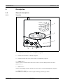
Fig. 4.2 Bottom view
953.92 | v1.0 | 2007.07
1.
Identification label
X
See Section 4.2.4 Identification label, page 20 for detailed description.
2.
Cable channels
3.
Wall mounting holes (distance between holes, 157 mm)
X
See Section 6.2.3 Wall installation, page 28 for detailed description.
4.
ON/OFF switch
5.
Serial No.
6.
LINE socket (used for firmware update)
X
See Section 13.7.1 LINE socket (unit bottom), page 86 for wiring.
7.
10V AC socket
X
See Section 13.7.2 Power socket (unit bottom), page 86 for wiring.
User Manual
TeleAlarm SA®
NurseCall Main Unit
4.1.3
Description | en
17
Front view
1
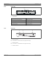
Fig. 4.3 Front view
1.
LED Indicator
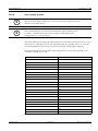
Status
LED
Standby mode (normal operation)
GREEN (permanent)
Backup battery low
GREEN (blinking)
Power supply disconnected
GREEN (flashing)
Help, Assistance or Fire
RED (blinking)
Programming mode
ORANGE (blinking)
Table 4.1 LED Indicator
4.1.4
Rear view
1
2
3
Fig. 4.4 Rear view
TeleAlarm SA®
1.
RS-232 connector
X
See Section 13.7.3 RS-232 (unit rear), page 87 for wiring.
2.
RS-485 connector
X
See Section 13.7.4 RS-485 (unit rear), page 87 for wiring.
3.
Antenna connector
User Manual
953.92 | v1.0 | 2007.07
18
en | Description
4.2
4.2.1
NurseCall Main Unit
Detailed description
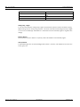
Loudspeaker
When one of the following Alarms/Messages is received by the NurseCall Main Unit, the internal
loudspeaker is activated (until Acknowledgement).
Status
Loudspeaker
Power supply disconnected
Dual-Tone beep every minute
Call for Help, Reserve Call, Technical Call
4 second interval, one tone
Error message
15 second interval, one tone
Disconnection of a Relay Unit from RS485-bus 1 minute interval, one tone
Call for Assistance / Fire Call
Continuously dual-tone beep
Local Acknowledgement
Short beep
Table 4.2
4.2.2
Loudspeaker
Display
The NurseCall Main Unit is equipped with a 2 x 20
characters display that guides the operator
NurseCall Main Unit
(c)
TeleAlarm SA
during the programming.
During normal operation, Alarms and Messages
are displayed.
4.2.3
Keyboard
The keyboard has 21 alphanumeric keys. They are used for NurseCall Main Unit programming
or during normal operation.
OFF
OK
ON
C
T
P
Fig. 4.5 Keyboard
953.92 | v1.0 | 2007.07
User Manual
TeleAlarm SA®
NurseCall Main Unit
Description | en
Keys
+
+
Programming Mode
Access to Parameters programming
X
Normal Operation
Not currently used
See Section 7.3 Parameters, page 39
Access to Transmitters programming
X
19
Not currently used
See Section 7.5 Transmitters, page 56
To scroll up to the next parameter
To increase the volume of the
loudspeaker
X
See Section 8.1 Loudspeaker
volume adjusting, page 61
To scroll down to the next parameter
To decrease the volume of the
loudspeaker
X
See Section 8.1 Loudspeaker
volume adjusting, page 61
To set a parameter value to OFF or to go to
To scroll down to the previous
the previous programming field
Alarm/Event
(example date: MM.DD.YY)
To set a parameter value to ON or to go to
To scroll up to the next
the next programming field
Alarm/Event
(example date: MM.DD.YY)
To confirm a value or a command
Not currently used
To cancel an entry or a command.
Not currently used
To quit the programming mode
To check the value of a Parameter or a
To check the status of the backup
Transmitter
battery
X
See Section 10.3 Backup battery monitoring and checking,
page 67
+
Not currently used
Not currently used
NPS programming function
Not currently used
X
See Section 7.1.2 Programming with NPS
software, page 36
to
To enter a value
Not currently used
To erase all programmed Acknowledgement
Not currently used
Transmitters during a specific procedure
X
See Section 7.5.8 Erasing all Acknowledgement Transmitters, page 60
Not currently used
To enter a value
Not currently used
To launch the Event/Alarm display
mode
Table 4.3 Keys functions
TeleAlarm SA®
User Manual
953.92 | v1.0 | 2007.07
20
en | Description
4.2.4
NurseCall Main Unit
Identification label
The identification label is located under the unit and permits its precise identification.
1
2
Nursecall
Main Unit (434)
NC.020.FI
REV A
YYMM
10 VAC
280 mA
50-60 Hz
TeleAlarm SA, CH-2300 La Chaux-de-Fonds, Switzerland
7
3
6
4
5
Fig. 4.6 Identification label
1.
Frequency in MHz
2.
Identification No. (NC = NurseCall, 020 = Main Unit, FI = Finished Product @ 434 MHz)
3.
Revision of software or hardware
4.
Month and Year of manufacturing
5.
*ESD pictogram
6.
**Crossed-out wastebasket symbol
7.
Voltage, current and frequency information
* The NurseCall Main Unit contains highly sensitive electronic components. It should be
opened only in an ESD protected environment.
** The NurseCall Main Unit is marked with a crossed-out wastebasket symbol. This means that,
at the end of its useful lifespan, the product shall be disposed separately from ordinary
household wastes in accordance to the EU Directive 2002/96/EC.
953.92 | v1.0 | 2007.07
User Manual
TeleAlarm SA®
NurseCall Main Unit
4.2.5
Description | en
21
RS-232 interface
A 9-pole SUB-D connector at the rear of the housing can be used for connection to a
–
printer;
–
paging system;
–
DECT phone system;
–
PC with Alarm Management Software.
NOTICE!
i
X
For the hardware configuration of this interface, see Section 6.2.6 Connecting the RS-232,
page 31.
X
For the programming of this interface, see Section 7.3.6 RS-232 output setting, page 46.
X
For the wiring of the connector, see Section 13.7.1 LINE socket (unit bottom), page 86.
Connection to a printer
To protocol all Events, a printer with serial connection (RS232-Interface) and endless paper
should be used. Printers with a parallel port can be used together with an intermediate serial
- parallel converter.
i
NOTICE!
The paper printout corresponds to the indication at the display of the NurseCall Main Unit.
Data rate: 9600 Bauds. Transmission: asynchronous with a 10 bit-structure
(1 startbit, 8 databits without parity, 1 stopbit).
The availability of the printer cannot be tested (switched on/off, paper).
The following printer is recommended:
–
SCRIPTOS.
Connection to a paging system
The NurseCall system uses several protocols, standard ESPA 4.4.4. protocol, a specific
Multitone protocol (Access 700-MEP) as well as the DeTeWe protocol.
X
See Section 13.5 Paging systems specifications, page 78 for more information about these
protocols.
Connection to a DECT phone system
The NurseCall system can transfer the received Alarms to DECT handsets Multitone CH60 or
CH70.
X
See Section 13.6 DECT phone system specifications, page 85 for more information about
this system.
TeleAlarm SA®
User Manual
953.92 | v1.0 | 2007.07
22
en | Description
NurseCall Main Unit
Connection to a PC using an Alarm Management Software
At connection / disconnection of a PC using an Alarm Management Software, Events are
generated.
The loudspeaker is disabled during the connection.
NOTICE!
i
Alarms/Messages arriving in the Alarm Buffer are repeated every 3 minutes until
Acknowledgement.
A technical defect (for example POWER OUTAGE) is treated as an Event
(no Acknowledgement necessary).
953.92 | v1.0 | 2007.07
User Manual
TeleAlarm SA®
NurseCall Main Unit
4.2.6
Description | en
23
RS-485 interface
One NurseCall Main Unit and up to 32 NurseCall Relay Units can be connected to a RS485-bus.
The bus must be connected to pins 2 and 5 of the units.
X
For connector wiring, see Section 13.7.4 RS-485 (unit rear), page 87.
CAUTION!
Keep polarity equal when connecting further units to the RS485 bus!
CAUTION!
Maximum RS485-bus length: 1200 m.
X
Use only one twisted pair cable for the interconnection.
NOTICE!
i
The Receiver Units located at the two ends of the bus should be terminated with a 100 Ohm
resistor.
X
See Section 6.2.8 Connecting the RS-485, page 33 for more information about the jumper
setting.
In this configuration, you always should connect the NurseCall Main Unit first. The NurseCall
Relay Units must then be connected to the RS485-bus one by one (not at the same time).
You can add a Printer Interface to the RS485-bus in order to connect an additional printer or a
giant display. In such configuration, the in-house paging system can be combined with a
printer without a PC.
Relay output
In the same connector, a potential free contact is available. It is a low current switching
contact. The relay (potential free, switching power max. 48 V / 0.5 A) is activated at a Call for
Help, Call for Assistance or Fire Call. This relay can be set as closing or switching contact (cycle
of 10 seconds on / 10 seconds off). This feature can be used to drive a signal lamp for
example.
4.2.7
X
For connector wiring, see Section 13.7.4 RS-485 (unit rear), page 87.
X
For relay setting, see Section 7.3.8 Output relay setting, page 50.
Antenna
The antenna is connected to the NurseCall Main Unit using the adapter supplied with the unit.
X
TeleAlarm SA®
See Section 6.2.4 Installing the antenna, page 29.
User Manual
953.92 | v1.0 | 2007.07
24
en | Description
953.92 | v1.0 | 2007.07
NurseCall Main Unit
User Manual
TeleAlarm SA®
NurseCall Main Unit
Transport | en
5
Transport
5.1
Transportation
5.1.1
25
Domestic
Suitable domestic transportation: by car, by truck, by postal parcel and by train.
5.1.2
International and overseas
For international and overseas transportation, hand the NurseCall Main Unit in its original
package to a shipping agent.
5.2
5.2.1
TeleAlarm SA®
Transportation data
Box dimensions
1.
Length: 39.0 cm (15.35 in)
2.
Width: 33.0 cm (12.99 in)
3.
Height: 60.0 cm (23.62 in)
4.
Weight: approx. 1500 g
User Manual
953.92 | v1.0 | 2007.07
26
en | Transport
953.92 | v1.0 | 2007.07
NurseCall Main Unit
User Manual
TeleAlarm SA®
NurseCall Main Unit
Installation | en
6
Installation
6.1
Unpacking
27
The NurseCall Main Unit is carefully packed for transportation.
The components contained in the box are protected, but should be handled with care.
Store the packaging material for further use (storage or transport).
In case of defective or missing equipment, do not try to install the NurseCall Main Unit.
X
1.
Contact immediately your local representative.
Take all components out of the box and place the NurseCall Main Unit on the working
space.
2.
Check each component in the box, in accordance with the list of contents below.
3.
Check that the NurseCall Main Unit and its accessories have not been damaged during
transportation.
6.1.1
List of contents
Reference
Description
NC.020.FI
NurseCall Main Unit
A 058
Power supply adaptor (Europe)
230VAC/10VAC
or
400-230/10
Power supply adaptor (UK)
230VAC/10VAC UK
or
400-115/10
Power supply adaptor (US)
115VAC/10VAC
A120
Antenna 434MHz 1/2 L=34 cm FME
A121
Straight adapter BFME-TNC
A122
Right angled bended adapter BFME-ETNC
C1239
2 m Cable FCC 6/4
953.92
NurseCall Main Unit User Manual
953.120
NurseCall - General Overview
Table 6.1 Packing list
TeleAlarm SA®
User Manual
953.92 | v1.0 | 2007.07
28
en | Installation
NurseCall Main Unit
6.2
Installation
6.2.1
Generalities
X
Install the NurseCall Main Unit in a dry place, away from any source of heat.
CAUTION!
Interferences
Avoid immediate proximity to other electric devices such as a television.
Tools
–
6.2.2
Torx T20 screwdriver.
Installation on a piece of furniture
It is recommended to place the NurseCall Main Unit on a non-sliding surface. However, do not
place anything (blanket, etc.) on top of the unit.
6.2.3
Wall installation
You can fasten the NurseCall Main Unit on a smooth wall surface using two screws (distance
between holes, 157 mm).
Power and line cords should be placed inside the channels on the bottom of the NurseCall
Main Unit.
953.92 | v1.0 | 2007.07
User Manual
TeleAlarm SA®
NurseCall Main Unit
6.2.4
Installation | en
29
Installing the antenna
i
NOTICE!
X
Use the straight adapter (4) for wall installation and the right angled bended adapter (3)
for installation on a piece of furniture.
1.
Fasten the adapter (3) or (4) on the antenna connector (1).
2.
Fasten the antenna (2) on the adapter.
1
Fig. 6.1 Rear view
2
4
2
3
Fig. 6.2 Installing the antenna
TeleAlarm SA®
User Manual
953.92 | v1.0 | 2007.07
30
en | Installation
6.2.5
NurseCall Main Unit
Connecting to the mains
The NurseCall Main Unit is powered by an adaptor (230 or 115/10VAC).
CAUTION!
In case of a different supply, the equipment must fulfil isolation requirements according to
EN60950 standard (fourth edition or later).
The power adaptor should be plugged in a socket-outlet placed near the unit and should be
easily accessible at any time.
The cable is connected to the modular contact labelled 10V AC (1), under the unit.
1
Fig. 6.3 Bottom view
X
953.92 | v1.0 | 2007.07
For connector wiring, see Section 13.7.2 Power socket (unit bottom), page 86.
User Manual
TeleAlarm SA®
NurseCall Main Unit
6.2.6
Installation | en
31
Connecting the RS-232
X
Connect the intended device by the 9-pole SUB-D connector (1) at the rear part of the
housing.
X
For connector wiring, see Section 13.7.3 RS-232 (unit rear), page 87.
1
Fig. 6.4 Rear view
i
NOTICE!
Inside the NurseCall Main Unit, the RS-232 interface should be configured with jumpers.
1.
Disassemble the unit as described in Section 10.5.2 Unit Dismantling, page 68.
2.
Remove the RS-232 board as described in Section RS-232 board removing, page 69.
3.
Set the jumpers as required in your configuration.
X
See Section 6.2.7 Setting the jumpers on RS-232 board, page 32
4.
Assemble the RS-232 board and the unit. This is basically the reverse of the dismantling
procedure.
TeleAlarm SA®
User Manual
953.92 | v1.0 | 2007.07
32
en | Installation
6.2.7
NurseCall Main Unit
Setting the jumpers on RS-232 board
i
NOTICE!
By default the jumpers are set for connection to DECT phone system.
The 4 jumpers are
mandatory
DECT
Fig. 6.5 Setting the jumpers for DECT phone system
Only these 2 jumpers
are mandatory
Alarm Management
Software or NPS
programming
Fig. 6.6 Setting the jumpers for Alarm Management Software or NPS programming
Only these 2 jumpers
are mandatory
Printer
and
paging
Fig. 6.7 Setting the jumpers for printers and paging systems
953.92 | v1.0 | 2007.07
User Manual
TeleAlarm SA®
NurseCall Main Unit
6.2.8
Installation | en
33
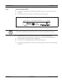
Connecting the RS-485
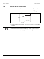
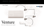
One NurseCall Main Unit and up to 32 NurseCall Relay Units can be connected to a RS485-bus.
Please contact a specialist for correct installation.
X
!
i
See Section 13.7.4 RS-485 (unit rear), page 87 for connector wiring.
CAUTION!
Do not use a star connection for the RS-485 network !
NOTICE!
The NurseCall Main or Relay Units located at the two ends of the bus must be terminated with
a 100 Ohm resistor.
X
See Section 6.2.9 Setting the 100 Ohm termination jumper, page 34.
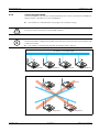
RS 485 bus (1 twisted pair cable)
100
100
®
m
seC
Nur
all
Te
leA
lar
®
®
m
seC
Nur
Relay Unit n
all
Te
leA
lar
m
seC
Nur
Relay Unit 2
all
V
lar
V
leA
V
V
®
Te
Te
leA
lar
m
l
Cal
se
Nur
Relay Unit 1
Main Unit
Fig. 6.8 Right connection
Main Unit
V
®
Te
leA
lar
m
seC
Nur
l
Cal
all
s
se
Nur
Relay Unit
Uni 1
leA
lar
m
seC
Nur
all
V
V
®
Te
Relay Unit 2
Relay Unit n
Fig. 6.9 Wrong connection
TeleAlarm SA®
User Manual
953.92 | v1.0 | 2007.07
34
en | Installation
6.2.9
NurseCall Main Unit
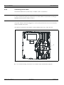
Setting the 100 Ohm termination jumper
Inside the NurseCall Main or Relay Units, the RS-485 interface can be configured with a jumper.
1.
Disassemble the unit as described in Section 10.5.2 Unit Dismantling, page 68.
2.
Remove the RS-232 board as described in Section RS-232 board removing, page 69.
3.
Put the 100 Ohm termination jumper J112 (1).
1
Fig. 6.10
4.
Setting the 100 Ohm termination jumper on the RS-232 board
Assemble the RS-232 board and the unit. This is basically the reverse of the dismantling
procedure.
i
953.92 | v1.0 | 2007.07
NOTICE!
If you do not want to disassemble the NurseCall Main Unit, you also can short-out the pins 3
and 4 of the connector. This has the same effect as the jumper setting described above.
X
See Section 13.7.4 RS-485 (unit rear), page 87 for connector wiring.
User Manual
TeleAlarm SA®
NurseCall Main Unit
Programming | en
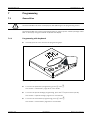
7
Programming
7.1
Generalities
!
35
CAUTION!
The NurseCall Main Unit does not display any Alarm/Message in the programming mode !
The NurseCall Main Unit can be programmed either by using a specific software package called
NPS or directly by using the "built-in" keyboard and display.
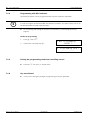
7.1.1
Programming with keyboard
X
Carefully open the cover and use the programming keys.
P
O
N
T
F
F
OK
O
C
Fig. 7.1 Programming with keyboard
X
To access the parameters programming, press
then
.
See Section 7.3 Parameters, page 39 for more details.
X
To access the special settings programming, press the
key three times quickly.
See Section 7.4 Special settings, page 51 for more details.
X
To access the Transmitters programming, press
then
.
See Section 7.5 Transmitters, page 56 for more details.
TeleAlarm SA®
User Manual
953.92 | v1.0 | 2007.07
36
en | Programming
7.1.2
NurseCall Main Unit
Programming with NPS software
The NurseCall system can be programmed with a specific software, called NPS.
i
NOTICE!
In order to program the NurseCall Main Unit with this software, you shall connect your PC to
the NurseCall Main Unit with a RS-232 cable.
X
For connecting and setting the interface, see Section 6.2.6 Connecting the RS-232,
page 31.
Enable the programming
1.
Press
2.
Confirm the command with
, then
.
.
X NPS Programming
READY ?...
X
7.1.3
Exiting the programming mode and cancelling entries
X
7.1.4
Press the
key once, or several times.
Key not allowed
X
953.92 | v1.0 | 2007.07
Programming NCall
.............
If you press a wrong key during the programming, a beep is generated.
User Manual
TeleAlarm SA®
NurseCall Main Unit
7.2
Programming | en
37
First use
At the first use or when you reset all parameters, the language, the Localization Mode and the
Display Mode for the Transmitters identification (floor / room / bed number or a single number)
should be programmed.
X
7.2.1
See also Section 7.4.2 Resetting all parameters (including date and time), page 51.
List of original factory settings
Parameter
Original Factory Setting
Page No.
Language
English
38
* Localization Mode
Yes (ON)
38
* Display Mode
FL,RO,BE (Floor / Room / Bed)
38
Output RS-232
None
46
RPE 670 for paging systems
No
47
Day/Night Mode
No
47
Night begin for paging or phone DECT systems 18h00
47
Night end for paging or phone DECT systems
06h00
47
ID paging for paging systems
2
47
ID NurseCall for paging systems
1
47
Number of digits for ESPA 4.4.4
3
47
Mix Mode ESPA 4.4.4 / Alarm Management
No
47
First number for DeTeWe paging system
1
47
Local Acknowledgement
Yes
50
Access Code for Local Acknowledgement
No
50
Output relay function
Continue
50
Output relay mode
Help + Assistance
50
Assistance and fire priority
No
52
Special texts in German
No
52
Set to Universal NurseCall
No
53
Conversion for Universal NurseCall
No
53
Last 300 ID codes blocked
No
53
Maximum number of Alarm Transmitters
500
54
Maximum number of Acknowledgement
5
55
Maximum number of Events buffered
18
55
Checking the daily messages
Yes
55
Repeat Alarms timing to RS-232 output
3 min.
55
Speaker Volume
Midrange
61
Software
for Universal NurseCall
Transmitters
Table 7.1 Original Factory Settings
* A reset of the unit is mandatory to change these two parameters.
TeleAlarm SA®
User Manual
953.92 | v1.0 | 2007.07
38
en | Programming
7.2.2
NurseCall Main Unit
Language
This step allows to select the interface language.
X
See Section 7.3.4 Programming the interface
language, page 45 for more details.
7.2.3
X Language 0
English
£
Localization Mode
i
NOTICE!
It is mandatory to perform a reset if you wish to change the value for the Localization Mode.
X
See also Section 7.4.2 Resetting all parameters (including date and time), page 51.
This step allows to switch OFF or ON the indication of the Transmitter position (Localization
Mode) on the NurseCall Main Unit display.
X
7.2.4
Press
to activate the Localization Mode or
press
to disable this function.
LOCALIZATION ?
( OFF / ON )
Display Mode
i
NOTICE!
It is mandatory to perform a reset if you wish to change the value for the Display Mode.
X
See also Section 7.4.2 Resetting all parameters (including date and time), page 51.
This step allows to select the Display Mode for the
Transmitters identification.
X
Press
to select FL,RO,BE (floor, room,
bed) or press
DISPLAY MODE ?
(NUMBER / FL,RO,BE)
to select NUMBER (Single
Number).
953.92 | v1.0 | 2007.07
User Manual
TeleAlarm SA®
NurseCall Main Unit
Programming | en
7.3
Parameters
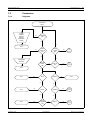
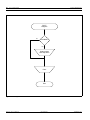
7.3.1
Diagrams
39
Parameters
Menu
English
Français
Deutsch
Italiano
Nederlands
Svensk
Yes
Language
(00)
No
No
End
Yes
Date
and Time
(01)
Relay
Output
(04)
Yes
Relay
Output
Diagram
No
No
Setting Date
and Time
RS-232
Output
(02)
No
Local Ack.
(03)
Yes
Local
Ack.
Diagram
End
Yes
No
End
Yes
None
S10-Du
Yes
End
No
No
Yes
End
Yes
Printer
PAGING
Yes
PAGING
Diagram
No
No
End
Fig. 7.2
Yes
Alarm
Management
SW
No
DECT
Yes
DECT
Diagram
Parameter Menu diagram
TeleAlarm SA®
User Manual
953.92 | v1.0 | 2007.07
40
en | Programming
NurseCall Main Unit
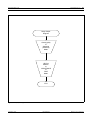
DECT
Diagram
No
DAY/NIGHT
Yes
Setting Night
and Day times
Filter
End
Fig. 7.3 DECT diagram
953.92 | v1.0 | 2007.07
User Manual
TeleAlarm SA®
NurseCall Main Unit
Programming | en
41
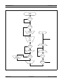
PAGING
Diagram
Yes
RPE670
No
No
DAY/NIGHT
Yes
Setting Night
and Day times
End
ESPA 4.4.4
or
MEP
or
DeTeWe
Protocol
Mix Mode
No
DeTeWe
Protocol ?
Yes
Setting the
first number
Nb. Digits
No
Setting
ID Paging and
ID NurseCall
Yes
ESPA 4.4.4
Protocol ?
Yes
RPE670
Yes
Filter
Fig. 7.4
ESPA 4.4.4
Protocol ?
No
PAGING diagram
TeleAlarm SA®
User Manual
953.92 | v1.0 | 2007.07
42
en | Programming
NurseCall Main Unit
Local Acknowledgement
Diagram
No
Local Ack.
enable ?
Yes
End
Acces code
input
No
Access
code
OK ?
Yes
No
Code for
Local
Ack. ?
Yes
Fig. 7.5 Local Acknowledgement diagram
953.92 | v1.0 | 2007.07
User Manual
TeleAlarm SA®
NurseCall Main Unit
Programming | en
43
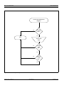
Relay Output
Diagram
Closing (ON)
or
Switching
(ON/OFF)
Mode
HELP &
ASSIST.
or
ASSISTANCE
or
FIRE
Mode
End
Fig. 7.6
Relay output diagram
TeleAlarm SA®
User Manual
953.92 | v1.0 | 2007.07
44
en | Programming
7.3.2
NurseCall Main Unit
Access to parameters
1.
Press
then
to access the parameters.
2.
Press
to program these parameters or
X
OK:Program
¤:Info
to check the value of each parameter.
3.
Select the parameter you wish to change/
or
check by scrolling with
7.3.3
.
X Parameter Nr. 00
Language
£
List of parameters
s
No.
Parameter
Reference
00
Language
Section 7.3.4 Programming the interface language, page 45
01
Date and Time
Section 7.3.5 Date and time setting, page 45
02
RS-232 Output
Section 7.3.6 RS-232 output setting, page 46
03
Local Ack.
Section 7.3.7 Local Acknowledgement setting, page 50
04
Relay Output
Section 7.3.8 Output relay setting, page 50
Table 7.2
953.92 | v1.0 | 2007.07
Programming references
User Manual
TeleAlarm SA®
NurseCall Main Unit
7.3.4
Programming | en
45
Programming the interface language
i
NOTICE!
This setting is also done during the first use.
X
See also Section 7.2 First use, page 37.
NOTICE!
You have the choice between 6 languages:
i
–
0 = English
–
1 = French
–
2 = German
–
3 = Italian
–
4 = Dutch
–
5 = Swedish
1.
Select the parameter No. 00.
2.
Press
3.
Select the language with the
X Parameter Nr. 00
Language
£
.
and
keys.
4.
7.3.5
Confirm the language selected with
.
£
X Parameter
Stored !
Date and time setting
1.
Select the parameter No. 01.
2.
Press
3.
Set the month with the
X Parameter Nr. 01
Date and Time
¡
.
and
X Date and Time
M·.DD.YY HH:MM:SS¡
keys.
key.
4.
Go to the day with the
5.
Set the day with the
and
6.
Go to the year with the
key.
7.
Set the year with the
8.
Same operation for the time setting
and
(HH:MM:SS).
9.
TeleAlarm SA®
X Language 0
English
Confirm the setting with
.
User Manual
keys.
keys.
X Date and Time
MM.D·.YY HH:MM:SS¡
X Date and Time
MM.DD.Y· HH:MM:SS¡
X Parameter
Stored !
953.92 | v1.0 | 2007.07
46
en | Programming
7.3.6
NurseCall Main Unit
RS-232 output setting
Parameter setting for RS-232 interface programming.
NOTICE!
Select one of the following:
i
–
None
–
Printer
–
Alarm Management SW
–
PAGING
–
DECT
–
S10-Du
1.
Select the parameter No. 02.
2.
Press
X
Set the desired value with the
X Parameter Nr. 02
RS-232 Output
¡
.
X RS-232 Output
Printer
keys.
3.
i
i
Confirm the setting with
and
.
¡
X Parameter
Stored !
NOTICE!
For the values None, Printer and Alarm Management SW, you do not have to define more
parameters. If you connect a paging or a DECT phone system, more parameters are available
NOTICE!
Inside the NurseCall Main Unit, the RS-232 interface should be configured with jumpers.
X
See Section 6.2.7 Setting the jumpers on RS-232 board, page 32.
X
For detailed paging or DECT phone system programming, see Section Example of
programming, page 47.
953.92 | v1.0 | 2007.07
User Manual
TeleAlarm SA®
NurseCall Main Unit
Programming | en
47
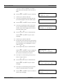
Example of programming
Paging or DECT phone system (RPE 670 system = YES, Day / Night transfer function = YES,
ESPA 4.4.4 protocol, Localization Mode = ON and Display Mode = NUMBER).
X
For more information about such systems, see Section 13.5.1 Multitone RPE670 with ESPA
4.4.4. protocol, page 78 and Section 13.6.1 Multitone DECT system CS600 and P318
interface, page 85.
1.
If you have selected PAGING, you should
select if you wish to use the RPE 670 system
(YES) or others (NO) with the
and
X PAGING
RPE 670 ? NO
¡
keys.
X
By using the DeTeWe protocol, you should
answer this question. Nevertheless, the
system ignores your response.
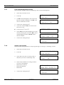
2.
3.
Confirm your selection with
.
Thereafter, or if you have selected DECT, you
should decide if you wish to activate the Day
/ Night transfer function (YES) or not (NO)
with the
and
X PAGING
Pager DAY-NIGHT NO ¡
keys.
4.
Confirm your selection with
X
If you have activated the Day / Night transfer
.
function, the NurseCall system transfers all
Alarms during Night to the group 24. At Day,
all groups 00 - 24 can be used. At the
moment of the switching from Day to Night
or vice versa, the message "DAY-NIGHT" is
transmitted to the activated pagers (DECT
phones), in order to signalize the change. In
this case, you should program the Night
starting time (default time = 18h00) and the
Night end time (default time = 06h00).
5.
Set the Night starting time and confirm your
setting with
6.
X
.
X PAGING
Night Beg.: HH:MM:SS
Set the Night end time and confirm your setting with
.
Use the
and
and the
and
keys for field selection
X PAGING
Night End : HH:MM:SS
keys for value
changing.
TeleAlarm SA®
User Manual
953.92 | v1.0 | 2007.07
48
en | Programming
NurseCall Main Unit
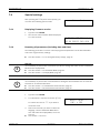
7.
If you have selected PAGING, you should
select the protocol (ESPA 4.4.4, DeTeWe or
MEP).
X
Use the
8.
Confirm your selection with
9.
and
keys for selection.
¡
.
If you have activated the DeTeWe protocol,
you should program the first number (0-9).
X
X PAGING
ESPA 4.4.4.
Use the
and
X 1.NUM. ---> 1
keys for selection.
10. If you have activated the ESPA 4.4.4 protocol, you should program the identification
number (0-9) of the paging system and the
XPAGING ESPA 4.4.4.
ID PAG.:2 ID NCALL:1
NurseCall system (0-9).
X
Use the
and
and the
keys for field selection
and
keys for value
changing.
11. Confirm your selection with
.
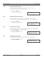
12. Decide how many characters per information
(criterion, floor, room, bed, position) should
be transmitted to the paging/DECT system
(filter function).
X
Use the
and
and the
keys for field selection
and
keys to change the
value. You can choose 0-11 characters for
CRITERION
<CRIT 09 + 3 SPACES
the criterion, followed by 0-9 spaces.
13. Press
to set the filtering of floor/room/
bed (or single number).
X
and
Use the
and the
keys for field selection
and
keys for values
changing.
14. Press
INFO.: fff
rrr 00b
FL:3+3 +RO:3+1 +BE:3
to set the filtering of the position
(only if Localization Mode is activated).
X
Use the
and
keys for number of
spaces (0-9) changing.
953.92 | v1.0 | 2007.07
User Manual
BE POS xyz
SPACES : 1
TeleAlarm SA®
NurseCall Main Unit
Programming | en
15. Confirm your selection with
49
.
16. If you have activated the ESPA 4.4.4 protocol
and selected the RPE 670 system, you
should select the number of digits (2, 3 or 4)
and
with the
XPAGING ESPA 4.4.4.
NB.DIGITS : 3
¡
keys.
17. Confirm your selection with
.
18. Thereafter, you should decide if you wish to
active the Mix Mode (YES) or not (NO).
X
Use the
and
keys to select YES
or NO.
19. Confirm your selection with
XPAGING ESPA 4.4.4.
MIX MODE : NO
¡
.
X Parameter
Stored !
Example of filtering
–
Display Mode: FR,RO,BE
–
Localization Mode: ON
–
Criterion filtering:
CR <CRIT 02 + 1 SPACES
2 characters and 1 space
–
Display Mode filtering:
1 character + 1 space for the floor number
2 characters + 0 space for the room number
2 characters for the bed number
–
Localization Mode filtering:
6 spaces between the bed number and
POS xyz.
INFO.: f rr0b
FL:1+1 +RO:2+0 +BE:2
BE
SPACES
POS xyz
: 6
In this example, a Call for Help from floor 008, room 023, bed 1 with the actual position 248
will generate the following sequence: "HE_8_2301______POS_248".
TeleAlarm SA®
User Manual
953.92 | v1.0 | 2007.07
50
en | Programming
7.3.7
NurseCall Main Unit
Local Acknowledgement setting
This parameter setting is used for the setting of the Local Acknowledgement.
1.
Select the parameter No. 03.
2.
Press
3.
Set NO if Acknowledgement at the NurseCall
X Parameter Nr. 03
Local Ack.
¡
.
Main Unit shall be disabled or set YES if you
wish to enable this function.
4.
5.
X Local Ack.
Possible ? YES
¡
.
Confirm the setting with
If you have selected YES, you should enter
the access code.
ACCESS CODE
X
Press the key
6.
Select YES if each Acknowledgement must be
then
.
··
done by entering the code 45 or NO if direct
Acknowledgement with the Green button
shall be enabled.
7.
Confirm the setting with
X Local Ack.
Access Code ? YES
¡
.
X Parameter
Stored !
7.3.8
Output relay setting
This parameter setting is used for relay programming as "closing" or "switching" contact.
1.
Select the parameter No. 04.
2.
Press
3.
Select ON if you wish a "closing" relay or
X Parameter Nr. 04
Relay Output
¢
.
ON/OFF if you wish a "switching" relay.
4.
X Relay Output
Fonc: 'ON'?
¡
Select relay activation according to Alarms.
You have 3 possibilities:
953.92 | v1.0 | 2007.07
–
Mode HELP & ASSIST;
–
Mode ASSISTANCE;
–
Mode FIRE;
5.
Confirm the setting with
X Relay Output
Mode HELP & ASSIST¡
.
User Manual
X Parameter
Stored !
TeleAlarm SA®
NurseCall Main Unit
7.4
Programming | en
51
Special settings
After pressing the
key three times quickly, you
Enter Code
can enter the following special codes.
7.4.1
Displaying firmware version
1.
Type the code 194155.
2.
The version of the firmware will be displayed
for a few seconds.
7.4.2
* TELEALARM NCALL3 *
V1.00 BN111.140.00A
Resetting all parameters (including date and time)
The following procedure is used to reset all programmed parameters of the NurseCall Main
Unit to the original factory settings.
X
See also Section 7.2.1 List of original factory settings, page 37.
NOTICE!
i
It is mandatory to perform this command if you wish to change the values for the Localization
Mode and the Display Mode.
X
See also Section 7.2.3 Localization Mode, page 38.
X
See also Section 7.2.4 Display Mode, page 38.
NOTICE!
i
It is mandatory to perform this command before setting the NurseCall Main Unit as Universal
NurseCall or as Standard NurseCall.
X
See also Section 7.4.7 Standard NurseCall selection, page 53.
X
See also Section 7.4.8 Universal NurseCall selection, page 53.
1.
Type the code 194156.
2.
A confirmation is required. Press the
to confirm the reset or
key
if you wish to
RESET TOTAL ?
(OK) = YES
cancel the reset.
3.
After a few seconds, you have to select the
language, set the Localization Mode ON or
OFF and select the Display Mode, as for the
first use.
X
TeleAlarm SA®
See Section 7.2 First use
User Manual
953.92 | v1.0 | 2007.07
52
en | Programming
7.4.3
NurseCall Main Unit
Assistance and fire priority
This command allows to set the Assistance Call and the Fire Call as a priority.
This means that this type of alarms is displayed first.
7.4.4
1.
Type the code 123991.
2.
Confirmation message displayed.
ASSISTANCE & FIRE
PRIORITY
Assistance and fire non priority
This command allows to set the Assistance Call and the Fire Call as non priority.
This means that the last alarm is displayed (whatever its type). This is the default value.
7.4.5
1.
Type the code 123992.
2.
Confirmation message displayed.
ASSISTANCE & FIRE
NONPRIORITY
Special texts in German
This command allows to set special texts in German. The displayed criteria are BAD/WC
instead of TECHNIK and HILFE-2 instead of NOTRUF2.
7.4.6
1.
Type the code 123007.
2.
Confirmation message displayed.
MULTITONE TEXTE
BAD/WC + HILFE-2
Standard texts in German
This command allows to set standard texts in German. This is the default value.
953.92 | v1.0 | 2007.07
1.
Type the code 123008.
2.
Confirmation message displayed.
User Manual
STANDARDTEXTE
TECHNIK + NOTRUF2
TeleAlarm SA®
NurseCall Main Unit
7.4.7
Programming | en
53
Standard NurseCall selection
This command allows to set the NurseCall as standard. This is the default value.
!
7.4.8
CAUTION! It is necessary to perform a general RESET before changing this value.
X
See Section 7.4.2 Resetting all parameters (including date and time), page 51.
1.
Type the code 001998.
2.
Confirmation message displayed.
UNIVERSAL NC? NO !
............
Universal NurseCall selection
!
CAUTION! It is necessary to perform a general RESET before changing this value.
X
See Section 7.4.2 Resetting all parameters (including date and time), page 51.
This command allows to set the NurseCall as ''Universal NurseCall''. If this mode is selected,
the following parameters are automatically set:
–
Display Mode set as FL,RO,BE (Floor/Room/Bed);
X
See Section 7.2.4 Display Mode, page 38.
–
RS-232 output set as Alarm Management SW;
X
See Section 7.3.6 RS-232 output setting, page 46.
–
50 Events selected.
X
See Section 7.4.11 Maximum number of Events buffered (toggle), page 55.
The ''Universal NurseCall'' breaks the limitation of 300 or 500 Transmitters by using a concept
in which the Transmitters are not recorded inside the NurseCall Main Unit.
In fact, the NurseCall Main Unit directly transfers each incoming radio ID code received from
the radio or from a Relay Unit to its RS-232 communication port.
The Alarm Management Software handles the radio codes.
The ID code is sent according to Display Mode Floor / Room / Bed.
Example:
ID code 1234 => Floor = 1; Room = 23; Bed = 4
TeleAlarm SA®
User Manual
953.92 | v1.0 | 2007.07
54
en | Programming
NurseCall Main Unit
Each type of Transmitter has its own ID code range. Regarding the type, the unit adds an offset
to the ID code:
Transmitter
ID code range
Offset
Data sent
S37, S35
1 to 4095
0
1 to 4095
S36-RAC-Old version
0 to 6560
0
0 to 6560
RAC-Fire
1 to 4095
6561
6562 to 10656
RAC-Fire-Old version
0 to 6560
6561
6561 to 13121
N45, N46
1 to 4095
13122
13123 to 17217
Table 7.3
Procedure
1.
Type the code 001999.
2.
Confirmation message displayed.
3.
Set the CONVERSION CODE OFF or ON with
the keys
X
and
.
UNIVERSAL NC? YES !
............
CONVERSION CODE ?
<OFF
ON>
If you select ON, the offset are ignored.
Then, the information sent out for
Transmitters RAC, N46 and S37 which have
the same ID code, is identical.
4.
Set the LAST 300 BLOCKED function OFF or
ON with the keys
X
and
.
LAST 300 BLOCKED ?
<OFF
ON>
If you select ON, the last 300 ID from
previous Transmitters which can reach 6560
(respectively 13121 for RAC-Fire) are not
managed!
7.4.9
Maximum number of Alarm Transmitters (toggle)
This command allows to set the maximum number of Alarm Transmitters
(300=OFF or 500=ON).
The default value is ON.
953.92 | v1.0 | 2007.07
1.
Type the code 001001.
2.
Confirmation message displayed.
User Manual
Enter Code
Parameter ON
TeleAlarm SA®
NurseCall Main Unit
7.4.10
Programming | en
55
Maximum number of Acknowledgement Transmitters (toggle)
This command allows to set the maximum number of Acknowledgement Transmitters
(5=OFF or 32=ON).
The default value is OFF.
7.4.11
1.
Type the code 001002.
2.
Confirmation message displayed.
Enter Code
Parameter ON
Maximum number of Events buffered (toggle)
This command allows to set the number of Events buffered (18=OFF or 50=ON).
The default value is OFF.
!
7.4.12
CAUTION! It is necessary to perform a general RESET before changing this value.
X
See Section 7.4.2 Resetting all parameters (including date and time), page 51.
1.
Type the code 001003.
2.
Confirmation message displayed.
Enter Code
Parameter ON
Daily message setting (toggle)
Periodically, a message is sent by each Transmitter in order to confirm its good functioning
condition. To avoid to saturate the Event Buffer, disable the daily message check performed by
the NurseCall Main Unit using this command (Parameter = ON).
("Daily message check enabled"=OFF or "Daily message check disabled"=ON).
The default value is OFF.
7.4.13
1.
Type the code 001007.
2.
Confirmation message displayed.
Enter Code
Parameter ON
RS232 message setting (toggle)
This command allows to set the delay for repeating the messages on the RS-232 interface.
("RS-232 repeat message every 3 minutes"=OFF or "RS-232 repeat message every 1
minute"=ON).
The default value is OFF.
TeleAlarm SA®
1.
Type the code 001009.
2.
Confirmation message displayed.
User Manual
Enter Code
Parameter ON
953.92 | v1.0 | 2007.07
56
en | Programming
NurseCall Main Unit
7.5
Transmitters
7.5.1
Generalities
X
7.5.2
To access the Transmitters programming, press
then
.
Alarm Transmitter programming
1.
Select the Alarm Transmitter type by pressing
(to scroll up) or
(to scroll
down). Then, confirm with
.
to program the Transmitter.
2.
Press
3.
Press the radio button of the Transmitter.
X
If the Transmitter is not accepted, see
Section 9 Troubleshooting, page 65.
4.
Enter the value for the floor, the room and
for the bed or a single number. Confirm each
value with
¯ Transmit. type : 0
Alarm Transmitter £
.
OK:Program
0:Erase ¤:Info
¯´ Press Radio
Button
¯ Transmitter code
accepted
¯ Floor
Value: 000
¯ Room
Value: 000
¯ Bed
Value: 0
5.
Enter the pager group value.
6.
Confirm the value with
X
See also Section 7.4.9 Maximum number of
.
Alarm Transmitters (toggle), page 54 to
¯ Pager
Value: 00
¯ Transmitter
Stored !
program the maximum number of Alarm
Transmitters (300 or 500).
953.92 | v1.0 | 2007.07
User Manual
TeleAlarm SA®
NurseCall Main Unit
7.5.3
Programming | en
57
Alarm Transmitter checking
1.
Select the Alarm Transmitter type by pressing
(to scroll up) or
(to scroll
¯ Transmit. type : 0
Alarm Transmitter
down). Then, confirm with
£
.
2.
Press
to check the Transmitter.
3.
Press the radio button of the Transmitter.
OK:Program
0:Erase ¤:Info
¯´ Press Radio
Button
¯ Transmitter code
accepted
¯ Floor
Value: 000
4.
Press
to see the room value.
¯ Room
Value: 000
TeleAlarm SA®
5.
Press
to see the bed value.
¯ Bed
Value: 0
6.
Press
to see the pager value.
¯ Pager
Value: 00
7.
Press
to go to the main menu.
User Manual
OK:Program
0:Erase ¤:Info
953.92 | v1.0 | 2007.07
58
en | Programming
7.5.4
NurseCall Main Unit
Alarm Transmitter erasing
1.
Select the Alarm Transmitter type by pressing
(to scroll up) or
(to scroll
¯ Transmit. type : 0
Alarm Transmitter
down). Then, confirm with
£
.
2.
Press
to erase the Transmitter.
3.
Press the radio button of the Transmitter.
4.
Press
to confirm the command.
OK:Program
0:Erase ¤:Info
¯´ Press Radio
Button
¯
Erase Radio
OK:Continue C:Abort
¯ Transmitter
Erased
953.92 | v1.0 | 2007.07
User Manual
TeleAlarm SA®
NurseCall Main Unit
7.5.5
Programming | en
59
Acknowledgement Transmitter programming
1.
Select the Acknowledgement Transmitter type
with
(to scroll up) or
(to scroll
¯ Transmit. type : 1
Ack. Transmitter
down). Then, confirm with
2.
Press
3.
Press the radio button of the Transmitter.
X
If the Transmitter is not accepted, see
to program the Transmitter.
Section 9 Troubleshooting, page 65.
X
¢
.
OK:Program
0:Erase ¤:Info
¯´ Press Radio
Button
Ack. Transmit.:1
Free:4
See also Section 7.4.10 Maximum number of
Acknowledgement Transmitters (toggle),
page 55 to program this value to 5 or 32.
7.5.6
Acknowledgement Transmitter checking
1.
Select the Acknowledgement Transmitter type
with
(to scroll up) or
(to scroll
¯ Transmit. type : 1
Ack. Transmitter
down). Then, confirm with
¢
.
2.
Press
to check the Transmitter.
3.
Press the radio button of the Transmitter.
OK:Program
0:Erase ¤:Info
¯´ Press Radio
Button
Ack. Transmit.:1
Free:4
TeleAlarm SA®
User Manual
953.92 | v1.0 | 2007.07
60
en | Programming
7.5.7
NurseCall Main Unit
Acknowledgment Transmitter erasing
1.
Select the Acknowledgement Transmitter type
with
(to scroll up) or
(to scroll
¯ Transmit. type : 1
Ack. Transmitter
down). Then, confirm with
2.
Press
to select the erase function.
3.
Press
to erase ONE Acknowledgement
Transmitter.
4.
5.
Press the radio button of the Transmitter.
Press
¢
.
to confirm the command.
OK:Program
0:Erase ¤:Info
¯ 'OK'= 1 Ack.Trans.
'*'= ALL !
¯´ Press Radio
Button
¯
Erase Radio
OK:Continue C:Abort
¯ Transmitter
Erased
7.5.8
Erasing all Acknowledgement Transmitters
1.
Select the Acknowledgement Transmitter type
with
(to scroll up) or
down). Then, confirm with
(to scroll
.
2.
Press
to select the erase function.
3.
Press
to erase ALL Acknowledgement
Transmitters.
4.
Confirm the command with
¯ Transmit. type : 1
Ack. Transmitter
¢
.
OK:Program
0:Erase ¤:Info
¯ 'OK'= 1 Ack.Trans.
'*'= ALL !
¯ ERASE ALL SLOTS !
OK:Continue C:Abort
¯ Ack. Transmitter
erased
953.92 | v1.0 | 2007.07
User Manual
TeleAlarm SA®
NurseCall Main Unit
Operating Instructions | en
8
Operating Instructions
8.1
Loudspeaker volume adjusting
8.2
X
Press the
key for higher volume.
X
Press the
key for lower volume.
61
Alarm- or Event Buffer consulting
The NurseCall Main Unit uses an Alarm Buffer and an Event Buffer for display indication.
Following Alarms/Messages are stored in the Alarm Buffer:
–
Call for Help;
–
Call for Assistance;
–
Reserve Call (Call for Help 2);
–
Technical Call;
–
Fire Call;
–
Battery Low Message;
–
Error Message;
–
Disconnection of a NurseCall Relay Unit from the RS485-bus.
If Alarms are repeated, only the "oldest" entry remains in the Buffer. The Call for Assistance
replaces the Call for Help, Reserve Call and Technical Call in the Alarm Buffer.
All possible entries are stored in the Event Buffer. Following messages are directly stored in
this Buffer:
i
–
Acknowledgement N46 (Sent by N46, S35 or S37);
–
Acknowledgement by Acknowledgement Transmitter S35 or S37;
–
Local Acknowledgement (Acknowledgement at the NurseCall Main Unit or Relay Unit);
–
Daily message check;
–
Personnel Arrival Message (A, B, C and D);
–
Personnel Departure Message;
–
Power outage of a Receiver Unit;
–
Return of power at a Receiver Unit;
–
Backup Battery Low of a Receiver Unit;
–
Interruption of the connection interface RS232 NurseCall <-> PC;
–
Return of the connection interface RS232 NurseCall <-> PC
–
Connection of a NurseCall Relay Unit to the RS485-bus;
–
Transmission of the Event "Door" by a RAC Transmitter.
NOTICE!
The Alarm and Event Buffers have a capacity of 18 or 50 entries.
X
See Section 7.4.11 Maximum number of Events buffered (toggle), page 55.
The Event Buffer will normally be filled with the last 18 or 50 entries. In the Alarm Buffer, only
the active Alarms are present.
TeleAlarm SA®
User Manual
953.92 | v1.0 | 2007.07
62
en | Operating Instructions
8.2.1
NurseCall Main Unit
Switching between Alarm and Event Buffers indication
i
i
953.92 | v1.0 | 2007.07
NOTICE!
The Alarm Buffer is indicated by default.
If you are in the Event Buffer, the unit changes automatically to the Alarm Buffer after 1 minute
without activity !
NOTICE!
If there are no entries in the Alarm Buffer, the display shows the actual date and time.
X
Switch from Alarm to Event Buffer and vice versa with the
X
Scroll the Alarms or the Events with buttons
User Manual
(upwards) or
key.An
(downwards).
TeleAlarm SA®
NurseCall Main Unit
8.2.2
Operating Instructions | en
63
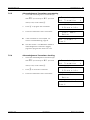
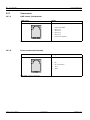
Display indications
i
NOTICE!
With the Yellow button, you can switch between three available information blocks.
Following information is displayed at Alarm/Message arriving:
First information block
–
In case of "floor / room / bed" Display Mode:
1.
Criterion of the Alarm/Message;
2.
Alarm (A) - or Event (E);
3.
Identification of the Transmitter location;
1
2
HELP
A03
FL:012 RO:015 BE:001
(floor/room/bed number).
3
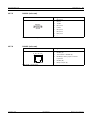
–
In case of "single number" Display Mode:
1.
Criterion of the Alarm/Message;
2.
Alarm (A) - or Event (E);
3.
Identification of the Transmitter location;
(single number).
In both Display Modes:
4.
Date of the Event;
3
1
2
HELP
NU:001
A03
3
Second information block
–
3
LOCAL ACK.
E02
06:05:04 13:33:05 C2
5.
Time of the Event;
6.
Main Unit (space) or Relay Unit (A...f)
7.
Quality of the received radio signal.
identification number;
4
5
6
7
Third information block
–
In both Display Modes:
8.
Position of the last passed beacon.
HELP
POS: 123
A01
8
In the Alarm Buffer, the total number of entries is
indicated on top at the right. You can immediately
see how many Alarms are active (in our example,
there are totally 3 Alarms in the Alarm Buffer.
HELP
NU:001
A03
On the other hand, in the Event Buffer the position
of the Event in the Buffer is indicated
(E01 corresponds to the latest entry in the Event
Buffer).
TeleAlarm SA®
User Manual
LOCAL ACK.
E01
06:05:04 13:33:05 C2
953.92 | v1.0 | 2007.07
64
en | Operating Instructions
NurseCall Main Unit
Unit displaying the current date and time
DATE:
TIME:
06.05.07
14:44:11
Unit displaying an active Alarm
HELP
NU:001
A01
LOCAL ACK.
NU:001
E04
Unit displaying an Event in the Buffer
8.2.3
Local Acknowledgement
X
The Local Acknowledgement is performed on the NurseCall Main Unit with the Green
button.
You can decide if you have to enter a code to confirm the Acknowledgement or not.
X
i
953.92 | v1.0 | 2007.07
See Section 7.3.7 Local Acknowledgement setting, page 50.
NOTICE!
The Alarm receiving an Acknowledgement is removed from the Alarm Buffer. The Alarm and its
Acknowledgement can then be found in the Event Buffer.
User Manual
TeleAlarm SA®
NurseCall Main Unit
Troubleshooting | en
9
Troubleshooting
9.1
"Ack. Transmitter already stored" message
65
This message is displayed if you are trying to program a Transmitter as Alarm Transmitter or
Acknowledgement Transmitter and this Transmitter was already stored as Acknowledgement
Transmitter.
9.2
"Radio in use" message
This message is displayed if you are trying to program a Transmitter as Alarm Transmitter and
this Transmitter was already stored as Alarm Transmitter.
NOTICE!
i
9.3
X
Press
X
Press
to continue (to perform an update of the values).
to abort the command.
The Green button does not work
If you are trying to acknowledge an Alarm with the Green button without success, the Local
Acknowledgement is probably disabled.
X
To activate the Local Acknowledgement function, see Section 7.3.7 Local Acknowledgement
setting, page 50.
TeleAlarm SA®
User Manual
953.92 | v1.0 | 2007.07
66
en | Troubleshooting
953.92 | v1.0 | 2007.07
NurseCall Main Unit
User Manual
TeleAlarm SA®
NurseCall Main Unit
Maintenance | en
10
Maintenance
10.1
System checking
X
67
Perform periodically an Alarm test in order to verify the correct function of your NurseCall
system.
10.2
Power supply monitoring
In case of a power failure, the NurseCall Main Unit
emits a warning tone and the following message
is displayed.
Main Power
Error
The backup battery ensures that the NurseCall Main Unit remains operational even in case of
power failure. When fully charged, the battery ensures a power backup of 24 hours. When
power returns after a power failure, the battery is recharged and, if it has been completely
discharged, it will reach its full capacity after 24 hours of charging time.
10.3
Backup battery monitoring and checking
i
NOTICE!
The status of the battery is indicated on the top right of the display.
X
The backup battery voltage is checked with
the
i
Checking
Local Battery
key.
NOTICE!
–
At startup, automatical checking.
–
Every 30 minutes, automatical checking.
X
If the remaining battery capacity drops
X
below 25 %, a warning message is displayed.
Local Battery
Empty
If the NurseCall Main Unit detects that the
Local Battery
Failure
backup battery is defective, a warning message is displayed.
X
If the backup battery is defective, replace it as described in Section 10.5.3 Backup battery
replacing, page 69.
TeleAlarm SA®
User Manual
953.92 | v1.0 | 2007.07
68
en | Maintenance
10.4
NurseCall Main Unit
Cleaning
CAUTION!
Avoid using cleaning products, cleansers or detergents.
X
Wipe off your NurseCall Main Unit occasionally with a dry cloth.
10.5
Parts replacement
10.5.1
Safety instructions
WARNING! Electro Static Discharge
The NurseCall Main Unit contains highly sensitive electronic components. It should be opened
only in an ESD protected environment with respect to the following precautions:
X
Discharge yourself from electrostatic loads by touching a grounded conductive surface
before opening the unit.
X
Avoid touching conductive parts inside the NurseCall Main Unit if not absolutely necessary.
CAUTION!
Never try to use replacement pieces other than those authorized by the manufacturer of the
NurseCall Main Unit.
10.5.2
Unit Dismantling
Antenna removing
1.
Remove the antenna (1) and its adapter (2) or (3).
1
3
1
2
Fig. 10.1
953.92 | v1.0 | 2007.07
Antenna removing
User Manual
TeleAlarm SA®
NurseCall Main Unit
Maintenance | en
69
RS-232 board removing
1.
Unscrew and remove the 4 screws (4) using a Torx T20 screwdriver.
2.
Unscrew and remove the screw (5) using a Torx T20 screwdriver.
3.
Carefully remove the RS-232 board (6).
4
5
6
Fig. 10.2 Unit dismantling and RS-232 board removing
10.5.3
Backup battery replacing
Important Safety Instructions
The battery shall be fully charged during 24 hours before using the NurseCall Main Unit for the
first time, after replacing the battery or after a long "power shortage".
i
NOTICE!
The battery will charge correctly between +5º C (+41º F) and +45º C (+113º F).
A new battery or one that has not been used for a long time could have reduced capacity the
first time it is used.
A rechargeable battery can be charged and discharged hundred of times. However, it will
eventually wear out . This not a defect. It is recommended to replace batteries that are not
anymore able to ensure a minimum power back-up time of 8 hours (at full charge).
TeleAlarm SA®
User Manual
953.92 | v1.0 | 2007.07
70
en | Maintenance
NurseCall Main Unit
WARNING!
–
May explode if exposed to fire;
–
Use only original batteries intended for use with your NurseCall Main Unit. Using other
type of batteries could be dangerous;
!
–
Do not expose the battery to liquids;
–
Do not let the metal contacts on the battery touch another metal. This could damage the
–
Do not disassemble or modify the battery;
–
Do not expose the battery to extreme temperatures, and never above 60º C ( +140º F ).
–
For maximum battery capacity, use the battery at room temperature;
–
Keep out of reach of children;
battery;
–
Use the battery for the intended purpose only;
–
Do not allow the battery to be put into the mouth. Battery electrolytes may be toxic if
swallowed.
CAUTION!
!
i
There is a risk of explosion if battery is replaced by a wrong type.
The battery should be replaced exclusively by Authorized Personnel.
Dispose of used batteries according to instructions and regulations.
NOTICE!
Battery type, 6V Ni/MH
Procedure
1.
Disassemble the unit like described in Section 10.5.2 Unit Dismantling, page 68.
2.
Disconnect the battery cable (1).
3.
Carefully remove the defective backup battery (2).
4.
Place the new backup battery.
5.
Connect the new battery cable (1).
2
Fig. 10.3
953.92 | v1.0 | 2007.07
1
Replacing the backup battery
User Manual
TeleAlarm SA®
NurseCall Main Unit
11
Storage | en
71
Storage
One can distinguish between long term storage and short term storage.
If the NurseCall Main Unit must be temporarily stored, it may not be necessary to wrap it completely.
However, if you wish to store the NurseCall Main Unit for longer time, for instance in a storage
room or any similar location, it is recommended to use original packing material.
11.1
Short term storage
11.1.1
Short term storage conditions
Unwrapped NurseCall Main Unit in a room:
–
11.1.2
Protection against direct sunlight and dust.
Long term storage conditions
i
NOTICE!
The NurseCall Main Unit does not loose its programmed parameters when the power supply
and the backup battery are disconnected.
NurseCall Main Unit in its original packing material in a storage room:
TeleAlarm SA®
–
Backup battery removed;
–
Protection against direct sunlight and dust.
User Manual
953.92 | v1.0 | 2007.07
72
en | Storage
953.92 | v1.0 | 2007.07
NurseCall Main Unit
User Manual
TeleAlarm SA®
NurseCall Main Unit
12
Disposal | en
73
Disposal
This chapter describes the appropriate disposal of the NurseCall Main Unit.
The NurseCall Main Unit is marked with a crossed-out wastebasket symbol.
This means that, at the end of its useful lifespan, the product shall be disposed separately
from ordinary household wastes in accordance to the EU Directive 2002/96/EC.
The product and its accessories shall be delivered to an appropriate collection facility that will
permit recycling, treatment and environmentally compatible disposal. This will prevent negative impact on the environment and human health and promotes the recycling of materials.
For more information on available collection facilities, contact your local waste collection service or your local representative.
12.1
Disassembly
Only Authorized Personnel is allowed to disassemble a NurseCall Main Unit.
12.2
Local disposal locations
The nearest disposal locations are established in conformance with the currently applicable
laws. Ask the local authorities.
12.3
Returning to the manufacturer
If there is no practical disposal place, the NurseCall Main Unit may be returned to your local
representative.
TeleAlarm SA®
User Manual
953.92 | v1.0 | 2007.07
74
en | Disposal
12.4
NurseCall Main Unit
Materials
The NurseCall Main Unit must be returned to an authorized point of destruction.
In order to protect people and environment, the NurseCall Main Unit must be destroyed in an
adequate manner. Consequently, all applicable laws and bylaws must be respected.
12.4.1
Battery
i
NOTICE!
The battery should never be placed in municipal waste. Use a battery disposal facility if available.
Fig. 12.1
X
Crossed-out wastebasket symbol
Please check local regulations for disposal of batteries or call your local representative
for information.
953.92 | v1.0 | 2007.07
User Manual
TeleAlarm SA®
NurseCall Main Unit
Appendix | en
13
Appendix
13.1
Electrical specifications
Voltage
230 or 115/10VAC
Current
280 mA
Frequency
50/60 Hz
Power
2.8 W max.
75
Table 13.1 Electrical specifications
13.2
Dimensions and weight
Casing dimensions
[mm]
Depth
220
Width
180
Height
40
Antenna
[mm]
Height
400
Casing weight
[g]
Weight
740
(including antenna and power supply adaptor)
Table 13.2 Dimensions and weight
13.3
Environmental conditions
Operating temperature
0 - 40°C
Table 13.3 Environmental conditions
TeleAlarm SA®
User Manual
953.92 | v1.0 | 2007.07
76
en | Appendix
13.4
NurseCall Main Unit
List of criteria
Criterion
Number
Alarm (A)
Comment
Transmitted to
transmitted or Event (E) DECT/paging
systems
to RS-232
ERROR
00
A
Yes
System malfunctioning.
Example: button defective
(N46)
PERSONNEL A
01
E
No
Coded key presence (N46)
LOW BATTERY
02
A
Yes
Battery at low level
(Transmitter)
ACK. N46
03
E
No
Acknowledgement
(Sent by N46, S35 or S37)
DOOR
04
E
No
Door open, then door closed
TECHNICAL
05
A
Yes
Technical Call (N46)
PERSONNEL C
06
E
No
Coded key presence (N46)
HELP
07
A
Yes
Call for Help
UNKNOWN
08
E
No
Not currently used
END PERSONNEL
09
E
No
Removed coded key (N46)
PERSONNEL D
10
E
No
Coded key presence (N46)
ASSISTANCE
11
A
Yes
Assistance Call
24 HOURS
12
E
No
Daily message check
RESERVE
13
A
Yes
Reserve Call (N46)
PERSONNEL B
14
E
No
Coded key presence (N46)
RADIO NOISE
15
E
No
Bad radio transmission (noise)
FIRE
16
A
Yes
Fire Call
ACK. TRANSM.1
17
E
No
Acknowledgement
(Ack. Transmitter No. 1)
LOCAL ACK.
18
E
No
Local Acknowledgement
(Main Unit or Relay Unit)
POWER OUTAGE
19
E
No
Main Unit or Relay Unit not
powered
POWER BACK
20
E
No
Powerer back
(Main Unit or Relay Unit)
COMPUTER OFF
21
E
No
Alarm management PC off
COMPUTER ON
22
E
No
Alarm management PC on
BAT.ACK.TRANSM
23
E
No
Battery at low level
(One of the Ack. Transmitter)
RELAY ON
24
E
No
Relay Unit on
RELAY OFF
25
A
No
Relay Unit off
NO RELAY
26
E
No
Relay Unit off acknowledged
(Main Unit)
LOW ACCU
27
E
No
Accumulator discharged
(Maint Unit or Relay Unit)
Table 13.4
953.92 | v1.0 | 2007.07
List of criteria
User Manual
TeleAlarm SA®
NurseCall Main Unit
Appendix | en
Criterion
Number
Alarm (A)
Transmitted to
77
Comment
transmitted or Event (E) DECT/paging
to RS-232
ACK. TRANSM.2
28
systems
E
No
Acknowledgement
(Ack. Transmitter No. 2)
ACK. TRANSM.3
29
E
No
Acknowledgement
(Ack. Transmitter No. 3)
ACK. TRANSM.4
30
E
No
Acknowledgement
(Ack. Transmitter No. 4)
ACK. TRANSM.5
31
E
No
Acknowledgement
(Ack. Transmitter No. 5)
ACK. TRANSM.xx
xx
E
No
Acknowledgement
(Ack. Transmitter No. xx)
ACK. TRANSM.32
58
E
No
Acknowledgement
(Ack. Transmitter No. 32)
Table 13.4 List of criteria
i
TeleAlarm SA®
NOTICE!
All Events are buffered into the Event Buffer of the NurseCall Main Unit.
User Manual
953.92 | v1.0 | 2007.07
78
en | Appendix
13.5
NurseCall Main Unit
Paging systems specifications
i
13.5.1
NOTICE!
The system uses 3 protocols, the standard ESPA 4.4.4. protocol, a specific Multitone protocol
(MEP) and the DeTeWe protocol.
Multitone RPE670 with ESPA 4.4.4. protocol
i
NOTICE!
Data rate: 9600 Bauds. Transmission: asynchronous with a 10 bit-structure
(1 startbit, 7 databits with even parity, 1 stopbit) in half-duplex mode.
Pagingsystem-ID = 2, NurseCall-ID=1.
Only Alarms/Messages arriving to the Alarm Buffer are transmitted (except "RELAY OFF"). The
transmission is fully alpha-numeric. The Alarms/Messages are repeated every 1 or 3 minutes
until Acknowledgement (see Section 7.4.13 RS232 message setting (toggle), page 55).
The Alarms/Messages are transmitted to the Multitone user number attributed to the
Transmitter (default group = 00).
Group
User number
00
12GG
01
13GG
02
14GG
03
15GG
04
16GG
05
17GG
06
18GG
07
19GG
08
20GG
09
21GG
10
22GG
11
23GG
12
24GG
13
25GG
14
26GG
15
27GG
16
28GG
17
29GG
18
30GG
19
31GG
20
32GG
21
33GG
Table 13.5
953.92 | v1.0 | 2007.07
Attribution table
User Manual
TeleAlarm SA®
NurseCall Main Unit
Appendix | en
Group
User number
22
34GG
23
35GG
24
36GG
79
Table 13.5 Attribution table
i
NOTICE!
In "floor / room / bed" Display Mode, use only alpha-numeric pagers which can store more than
16 characters.
Change Day / Night
If you have activated the change Day / Night, the NurseCall system transfers all Alarms during
Night to the group 24. At Day, all groups 00 - 24 can be used. When switching from Day to Night
or vice versa, the Message "DAY-NIGHT" is transmitted to the activated pagers to signalize the
change.
Priority Alarms
The Assistance and Fire Alarms are priority calls transmitted to all activated pagers.
Call repetition
If Alarms/Messages are not acknowledged after about 7 minutes, call repetitions are also sent
to the group 23.
13.5.2
Multitone RPE670 with MEP protocol
i
NOTICE!
Data rate: 1200 Bauds. Transmission: asynchronous with a 10 bit-structure
(1 startbit, 7 databits with even parity, 1 stopbit) in half-duplex mode.
Only Alarms/Messages arriving to the Alarm Buffer are transmitted (except "RELAY OFF"). The
transmission is only numeric. The Alarms/Messages are repeated every 1 or 3 minutes until
Acknowledgement (see Section 7.4.13 RS232 message setting (toggle), page 55).
The Alarms/Messages are transmitted to the Multitone user number attributed to the
Transmitter (default group = 00).
Group
User number
00
12GG
01
13GG
02
14GG
03
15GG
04
16GG
05
17GG
Table 13.6 Attribution table
TeleAlarm SA®
User Manual
953.92 | v1.0 | 2007.07
80
en | Appendix
NurseCall Main Unit
Group
User number
06
18GG
07
19GG
08
20GG
09
21GG
10
22GG
11
23GG
12
24GG
13
25GG
14
26GG
15
27GG
16
28GG
17
29GG
18
30GG
19
31GG
20
32GG
21
33GG
22
34GG
23
35GG
24
36GG
Table 13.6
X
Attribution table
Use pagers with "alpha-text" and which are coded as follows:
Code
Alarm / Message
00
Acknowledgement
06
Call for Help
09
Call for Assistance
02
Reserve Call
15
Technical Call
07
Fire Call
03
Battery Low Message
01
Error Message
04
"DAY-NIGHT" message to signalize the change
from Day to Night.
Table 13.7
!
953.92 | v1.0 | 2007.07
Attribution table
CAUTION!
The transmission takes only place in "single number" Display Mode.
X
See Section 7.2.4 Display Mode, page 38.
User Manual
TeleAlarm SA®
NurseCall Main Unit
Appendix | en
81
Change Day / Night
If you have activated the change Day / Night, the NurseCall system transfers all Alarms during
Night to the group 24. At Day, all groups 00 - 24 can be used. When switching from Day to Night
or vice versa, the Message "DAY-NIGHT" is transmitted to the activated pagers to signalize the
change.
Priority Alarms
The Assistance and Fire Alarms are priority calls transmitted to all activated pagers.
Call repetition
If Alarms/Messages are not acknowledged after about 7 minutes, call repetitions are also sent
to the group 23.
13.5.3
DeTeWe protocol
i
NOTICE!
Data rate: 9600 Bauds. Transmission: asynchronous with a 10 bit-structure
(1 startbit, 8 databits with odd parity, 1 stopbit) in half-duplex mode.
Only Alarms/Messages arriving to the Alarm Buffer are transmitted (except "RELAY OFF"). The
transmission is fully alpha-numeric. The Alarms/Messages are repeated every 1 or 3 minutes
until Acknowledgement (see Section 7.4.13 RS232 message setting (toggle), page 55).
The Alarms/Messages are transmitted to the paging system user number attributed to the
Transmitter (default group = 00).
Group
User number
00
x00
01
x01
02
x02
03
x03
04
x04
05
x05
06
x06
07
x07
08
x08
09
x09
10
x10
11
x11
12
x12
13
x13
14
x14
15
x15
Table 13.8 Attribution table
TeleAlarm SA®
User Manual
953.92 | v1.0 | 2007.07
82
en | Appendix
NurseCall Main Unit
Group
User number
16
x16
17
x17
18
x18
19
x19
20
x20
21
x21
22
x22
23
x23
24
x24
Table 13.8
i
Attribution table
NOTICE!
The x value can be programmed.
–
See Section Example of programming, page 47.
Change Day / Night
If you have activated the change Day / Night, the NurseCall system transfers all Alarms during
Night to the group 24. At Day, all groups 00 - 24 can be used. When switching from Day to Night
or vice versa, the Message "DAY-NIGHT" is transmitted to the activated pagers to signalize the
change.
Priority Alarms
The Assistance and Fire Alarms are priority calls transmitted to all activated pagers.
Call repetition
If Alarms/Messages are not acknowledged after about 7 minutes, call repetitions are also sent
to the group 23.
953.92 | v1.0 | 2007.07
User Manual
TeleAlarm SA®
NurseCall Main Unit
13.5.4
Appendix | en
83
Other paging systems
i
i
NOTICE!
Multitone Access 3000 compact, etc. can be connected if configured correctly
(RPE 670 = NO, ESPA 4.4.4.).
NOTICE!
Data rate: 9600 Bauds. Transmission: asynchronous with a 10 bit-structure
(1 startbit, 7 databits with even parity, 1 stopbit) in half-duplex mode.
Pagingsystem-ID = 2, NurseCall-ID=1.
Only Alarms/Messages arriving to the Alarm Buffer are transmitted (except "RELAY OFF"). The
transmission is fully alpha-numeric. The Alarms/Messages are repeated every 1 or 3 minutes
until Acknowledgement (see Section 7.4.13 RS232 message setting (toggle), page 55).
The Alarms/Messages are transmitted to the paging system user number attributed to the
Transmitter (default group = 00).
Group
User number
00
999
01
998
02
997
03
996
04
995
05
994
06
993
07
992
08
991
09
990
10
989
11
988
12
987
13
986
14
985
15
984
16
983
17
982
18
981
19
980
20
979
21
978
Table 13.9 Attribution table
TeleAlarm SA®
User Manual
953.92 | v1.0 | 2007.07
84
en | Appendix
NurseCall Main Unit
Group
User number
22
977
23
976
24
Table 13.9
975
Attribution table
Change Day / Night
If you have activated the change Day / Night, the NurseCall system transfers all Alarms during
Night to the group 24. At Day, all groups 00 - 24 can be used. When switching from Day to Night
or vice versa, the Message "DAY-NIGHT" is transmitted to the activated pagers to signalize the
change.
Priority Alarms
The Assistance and Fire Alarms are priority calls transmitted to all activated pagers.
Call repetition
If Alarms/Messages are not acknowledged after about 7 minutes, call repetitions are also sent
to the group 23.
953.92 | v1.0 | 2007.07
User Manual
TeleAlarm SA®
NurseCall Main Unit
13.6
Appendix | en
85
DECT phone system specifications
i
13.6.1
NOTICE!
The system can transfer the Alarms received to DECT handsets of the types Multitone CH60 or
CH70.
Multitone DECT system CS600 and P318 interface
i
NOTICE!
Data rate: 9600 Bauds. Transmission: asynchronous with a 10 bit-structure
(1 startbit, 7 databits with even parity, 1 stopbit) in half-duplex mode.
Only Alarms/Messages arriving to the Alarm Buffer are transmitted (except "RELAY OFF"). The
transmission is fully alpha-numeric. The Alarms/Messages are repeated every 1 or 3 minutes
until Acknowledgement (see Section 7.4.13 RS232 message setting (toggle), page 55).
The transmission to the DECT system is a team call. The team number must match with the
paging group programmed for every single
(default paging group= 00).
Change Day / Night
If you have activated the change Day / Night, the NurseCall system transfers all Alarms during
Night to the group 24. At Day, all groups 00 - 24 can be used. When switching from Day to Night
or vice versa, the Message "DAY-NIGHT" is transmitted to the activated pagers to signalize the
change.
Priority Alarms
The Assistance and Fire Alarms are priority calls transmitted to all activated DECT handsets.
Call repetition
If Alarms/Messages are not acknowledged after about 7 minutes, call repetitions are also sent
to the group 23.
TeleAlarm SA®
User Manual
953.92 | v1.0 | 2007.07
86
en | Appendix
NurseCall Main Unit
13.7
Connectors
13.7.1
LINE socket (unit bottom)
LINE socket
Wiring
1.
Flash Data GND
2.
Not used
3.
Not used
4.
Not used
5.
Not used
6.
Flash Data IN/OUT
1 2 3 456
Table 13.10 Line socket wiring
13.7.2
Power socket (unit bottom)
10V AC socket
Wiring
1.
NC
2.
AC-1 10-12VAC
3.
AC-2
4.
GND
1 2 3 4
Table 13.11 Power socket wiring
953.92 | v1.0 | 2007.07
User Manual
TeleAlarm SA®
NurseCall Main Unit
13.7.3
Appendix | en
87
RS-232 (unit rear)
RS-232 socket
Wiring
1.
RTS/CTS
2.
RX/TX
54321
3.
TX/RX
4.
RTS/CTS
9876
5.
0 Volt
6.
RTS/CTS
7.
RTS/CTS
8.
RST/CTS
9.
---
Table 13.12 RS-232 wiring
13.7.4
RS-485 (unit rear)
RS-485
Wiring
1 2 3 4 5 6
1.
Relay output (a)
2.
RS485 (A)
3.
Termination = RS485 (A)
4.
RS485(A) when jumper end line
is placed
5.
RS485 (B)
6.
Relay Output (b)
Table 13.13 RS-485 wiring
TeleAlarm SA®
User Manual
953.92 | v1.0 | 2007.07
88
en | Appendix
13.8
NurseCall Main Unit
EC-Declaration of conformity
Fig. 13.1 EC-Declaration of conformity, page 1
953.92 | v1.0 | 2007.07
User Manual
TeleAlarm SA®
NurseCall Main Unit
Fig. 13.2
Appendix | en
89
EC-Declaration of conformity, page 2
TeleAlarm SA®
User Manual
953.92 | v1.0 | 2007.07
90
en | Appendix
NurseCall Main Unit
Fig. 13.3 EC-Declaration of conformity, page 3
953.92 | v1.0 | 2007.07
User Manual
TeleAlarm SA®
NurseCall Main Unit
14
Glossary | en
91
Glossary
A
Acknowledgement
Alarm receipt or reset.
Acknowledgement
Transmitter
Transmitter used to acknowledge alarms.
Alarm
Automatic signal to warn of a danger.
Alarm Buffer
Memory used to store alarms.
Alarm Management
Software
Software installed on a PC to manage alarms or messages.
Alarm Transmitter
Radio transmitter used for alarm triggering (S37 for example).
Assistance Call
Alarm sent to ask for assistance.
Authorized Personnel Persons who are authorized by their training to perform specific activities with the
NurseCall Main Unit. An electrician is designated as Authorized Personnel involved with the
activities related to the connecting of the NurseCall Main Unit to the electric power supply.
B
Buffer
Memory used to store events or alarms.
C
Call for Assistance
Alarm sent to ask for assistance.
Call for Help
Alarm sent to ask for help.
Call for Help 2
Alarm sent to ask for help (N46, reserve call).
D
Day
Time duration defined between Night end time and Night starting time.
During the Night, the alarms are transfered to the paging group 24.
E
Event
Alarm receiving an acknowledgement. The alarm and its acknowledgement are thereafter
defined as event.
Event Buffer
Memory used to store events.
Event "Door"
Special event sent when a door is passed.
F
Fire Alarm
Alarm sent in case of fire.
Fire Call
Alarm sent in case of fire.
TeleAlarm SA®
User Manual
953.92 | v1.0 | 2007.07
92
en | Glossary
NurseCall Main Unit
I
Installer
Persons who are authorized by their training to perform the installation of your system.
L
Local
Acknowledgement at the NurseCall Main Unit or Relay Unit.
Acknowledgement
Localization Mode
Special mode used to send the transmitter position.
M
Main Unit
Receiver unit used to manage and store the alarms and messages arriving from NurseCall
Transmitters.
Message
Signal transmitted to a receiver for information (for example, "DOOR").
N
Night
Time duration defined between Night starting time and Night end time.
During the Night, the alarms are transfered to the paging group 24.
NurseCall
Your smart system.
P
Parameter
A user-adjustable value that governs some aspect of a device's performance
(Example, Night starting time).
R
Receiver Unit
Main Unit or Relay Unit.
Relay Unit
Receiver unit used to improve radio reception range.
Reserve Call
Alarm sent to ask for help (N46, Call for Help 2).
T
Technical Alarm
Alarm triggered by activating a contact in the N46.
Transmitter
A device used for the generation of signals of any type and form that are to be transmitted.
U
User
953.92 | v1.0 | 2007.07
Persons who are authorized by their training to use the NurseCall system.
User Manual
TeleAlarm SA®
TeleAlarm SA Bosch Group
Unterer Quai 37
CH-2502 Biel-Bienne
Switzerland
Phone
+41 32 327 25 40
Fax
+41 32 327 25 41
[email protected]
www.telealarm.com
Bosch Security Systems France
Atlantic 361
361, avenue du Général de Gaulle
F-92147 Clamart
France
Phone
+ 33 (0)825 12 8000
(0, 15 € TTC/Min)
Fax
+ 33 (0)820 900 960
(0, 12 € TTC/Min)
[email protected]
www.boschsecurity.fr
Bosch Security Systems Ltd
Broadwater Park
North Orbital Road
Denham
UB9 5HN
United Kingdom
Phone
01895-878088
Fax
01895-878089
[email protected]
www.boschsecurity.co.uk
Haus-ServiceRuf
Bosch Sicherheitssysteme GmbH
Ingersheimer Straße 16
D-70499 Stuttgart
Germany
Phone
01805 231232*)
Fax
0711 811-5125 294
*)0,14 € pro Minute aus dem Festnetz der Deutschen Telekom
[email protected]
www.bosch-hausserviceruf.de
Bosch Security Systems BV
Postbus 80002
5600 JB Eindhoven
Nederland
Phone
+31 40 25 77 209
Fax
+31 40 25 77 428
[email protected]
www.boschsecurity.nl
Bosch Security Systems AB
Kansligatan 10
SE-602 09 Norrköping
Sweden
Phone
+46 (0)11 28 04 80
Fax
+46 (0)11 28 04 89
[email protected]
www.boschsecurity.se
Bosch Security Systems nv/sa
Torkonjestraat 21F
B-8510 Marke
Belgium
Phone
+32 (0)56 20 02 40
Fax
+32 (0)56 20 26 75
[email protected]
www.boschsecurity.be