1
NETWORK GATEWAY SERIES
ICC
INDUSTRIAL CONTROL COMMUNICATIONS, INC.
ICC
INDUSTRIAL CONTROL COMMUNICATIONS, INC.
Madison Office
1600 Aspen Commons, Suite 210
Middleton, WI USA 53562-4720
Tel: [608] 831-1255 Fax: [608] 831-2045
http://www.iccdesigns.com
ETH-200
Houston Office
12300 Dundee Court, Suite 212
Cypress, TX USA 77429-8364
Printed in U.S.A
ETHERNET MULTIPROTOCOL NETWORK GATEWAY
August 2008
ICC #10595-1.130-001
Introduction
Thank you for purchasing the ICC ETH-200 Ethernet Multiprotocol Network
Gateway. The ETH-200 allows information to be transferred seamlessly
between many different fieldbus networks with minimal configuration
requirements. The ETH-200 provides a 10/100BaseT Ethernet port, two
RS485 ports, one RS232 port, and three common serial ports for direct
connectivity to Toshiba 7-series, 9-series, 11-series, VFAS1 or VF-nC1
Adjustable Speed Drives (ASDs). These various communication ports operate
independently, and are configurable along with the unit’s internal point
database via a standard web browser.
The gateway currently provides support for the following protocols:
•
•
•
•
•
•
•
•
Modbus RTU (RS485 master & slave)
Modbus RTU (RS232 master & slave)
Toshiba ASD (common serial master)
Toshiba ASD (RS485 master)
Toshiba 3-series ASD (RS232 master)
Modbus TCP/IP (slave)
Ethernet/IP (server)
Mitsubishi 500-series & 700-series ASD (RS485 master)
New network drivers are continuously being added, and can be downloaded for
free from our web site.
Before using the ETH-200 network gateway, please familiarize yourself with the
product and be sure to thoroughly read the instructions and precautions
contained in this manual. In addition, please make sure that this instruction
manual is delivered to the end user of the ETH-200, and keep this instruction
manual in a safe place for future reference or unit inspection.
This instruction manual describes the device specifications, wiring methods,
maintenance procedures, supported functions and usage methods for the ETH200 network gateway.
For the latest information, support, firmware releases or product point files,
please visit http://www.iccdesigns.com.
Before continuing, please take a moment to ensure that you have received all
materials shipped with your kit. These items are:
•
•
•
ETH-200 gateway
Panel-mount standoff kit
Documentation CD-ROM
1
ETH-200 Ethernet Multiprotocol Network Gateway
User's Manual
Part Number 10595-1.120-000
Printed in U.S.A.
©2007 Industrial Control Communications, Inc.
All rights reserved
Industrial Control Communications, Inc. reserves the right to make changes
and improvements to its products without providing notice.
Notice to Users
INDUSTRIAL CONTROL COMMUNICATIONS, INC.’S PRODUCTS ARE NOT
AUTHORIZED FOR USE AS CRITICAL COMPONENTS IN LIFE-SUPPORT
DEVICES OR SYSTEMS. Life-support devices or systems are devices or
systems intended to sustain life, and whose failure to perform, when properly
used in accordance with instructions for use provided in the labeling and user's
manual, can be reasonably expected to result in significant injury.
No complex software or hardware system is perfect. Bugs may always be
present in a system of any size. In order to prevent danger to life or property, it
is the responsibility of the system designer to incorporate redundant protective
mechanisms appropriate to the risk involved.
2
Usage Precautions
Operating Environment
•
Please use the gateway only when the ambient temperature of the
environment into which the unit is installed is within the following
specified temperature limits:
Operation: -10 ∼ +50°C (+14 ∼ +122°F)
-40 ∼ +85°C (-40 ∼ +185°F)
Storage:
•
Avoid installation locations that may be subjected to large shocks or
vibrations.
Avoid installation locations that may be subjected to rapid changes in
temperature or humidity.
•
Installation and Wiring
•
•
Proper ground connections are vital for both safety and signal reliability
reasons. Ensure that all electrical equipment is properly grounded.
Route all communication cables separate from high-voltage or noiseemitting cabling (such as ASD input/output power wiring).
ASD Connections
•
•
•
•
•
•
Do not touch charged parts of the drive such as the terminal block
while the drive’s CHARGE lamp is lit. A charge will still be present in
the drive’s internal electrolytic capacitors, and therefore touching these
areas may result in an electrical shock. Always turn all drive input
power supplies OFF, and wait at least 5 minutes after the CHARGE
lamp has gone out before connecting communication cables.
To avoid misoperation, do not connect any gateway terminals to either
the ASD’s E/GND terminals, the motor, or to any other power ground.
When making common serial connections between the gateway and
Toshiba ASDs, do not use cables that exceed 5 meters in length.
For further drive-specific precaution, safety and installation information,
please refer to the appropriate documentation supplied with your drive.
Internal ASD EEPROMs have a limited life span of write cycles.
Observe all precautions contained in this manual and your ASD
manual regarding which drive registers safely may and may not be
repetitively written to.
When used without an Auxiliary power source (Toshiba ASD common
serial mode), the gateway derives its control power from the connected
drives. Therefore, removing power to all connected drives will also
cause the gateway to lose power.
3
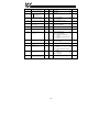
TABLE OF CONTENTS
1.
The Network Gateway Series Concept.......................................7
2.
Feature Summary..........................................................................8
3.
Installing the Gateway................................................................11
3.1
Mounting .............................................................................................11
3.1.1 Panel Mounting ...............................................................................11
3.1.2 SnapTrackTM Mounting ...................................................................12
3.1.3 DIN Rail Mounting...........................................................................12
3.2
Installation for Non-Toshiba ASD Networks ........................................13
3.3
Toshiba Common Serial ASD Network Installation .............................13
3.3.1 Installation for G7 ASDs..................................................................14
3.3.2 Installation for S7, S9, S11, A7 and VF-nC1 ASDs.........................16
4.
RS485 Port Electrical Interfaces ...............................................18
5.
Environmental Specifications ...................................................19
6.
Maintenance and Inspection .....................................................20
7.
Storage and Warranty ................................................................21
7.1
7.2
8.
8.1
8.2
8.3
8.4
9.
Storage................................................................................................21
Warranty..............................................................................................21
LED Indicators ............................................................................22
Toshiba ASD Common Serial Port Indicators .....................................22
Ethernet Port Indicators.......................................................................22
RS485 Port Indicators .........................................................................22
Ethernet/IP Status Indicators...............................................................22
Configuration Switches .............................................................23
10.
Auxiliary Power Supply..........................................................23
11.
Internal Battery........................................................................23
12.
Unit Configuration Concepts.................................................24
12.1
12.2
12.3
12.4
Port and Protocol Configuration ..........................................................24
Timeout Configuration .........................................................................24
Point Configuration..............................................................................25
General Configuration Procedure........................................................27
13.
Initial Ethernet Configuration ................................................28
4
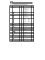
13.1
13.2
ARP Method ....................................................................................... 28
Console Method ................................................................................. 29
14.
Console Access ......................................................................30
14.1
RS232................................................................................................. 30
14.1.1
Requirements............................................................................. 30
14.1.2
Connection................................................................................. 30
14.1.3
Application Configuration ........................................................... 31
14.2
Telnet ................................................................................................. 33
14.2.1
Requirements............................................................................. 33
14.2.2
Connection................................................................................. 33
14.2.3
Application Configuration ........................................................... 33
14.3
Command Overview ........................................................................... 34
15.
Embedded Web Server...........................................................38
15.1
Authentication..................................................................................... 39
15.2
Communication Status Indicators ....................................................... 40
15.3
Unit Status .......................................................................................... 40
15.4
Set Date and Time.............................................................................. 41
15.5
Network Configuration ........................................................................ 41
15.6
Authentication Configuration............................................................... 41
15.7
Port Configuration............................................................................... 42
15.7.1
Toshiba ASD Common Serial Port Configuration ...................... 43
15.7.2
RS232 and RS485 Port Configuration ....................................... 43
15.7.3
Modbus TCP/IP Configuration ................................................... 43
15.7.4
Ethernet/IP Port Configuration ................................................... 44
15.8
Point Configuration ............................................................................. 44
15.9
Upload Port and Point Configuration .................................................. 47
15.10
Radix Selection .............................................................................. 48
15.11
Editing Point Values ....................................................................... 48
15.12
Error Code Reference .................................................................... 49
16.
Protocol-Specific Information ...............................................50
16.1
Modbus............................................................................................... 50
16.1.1
Coil & Discrete Input Mappings.................................................. 51
16.1.2
Modbus RTU Slave.................................................................... 52
16.1.3
Modbus RTU Master.................................................................. 52
16.1.4
Modbus TCP/IP Slave................................................................ 53
16.2
Ethernet/IP.......................................................................................... 54
16.3
Toshiba Common Serial ASD Protocol............................................... 56
16.4
Toshiba RS485 ASD Protocol ............................................................ 56
16.5
Mitsubishi ASD Protocol ..................................................................... 59
5
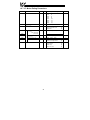
16.6
Teco-Westinghouse ASDs ..................................................................63
16.6.1
MA7200 ......................................................................................63
16.6.2
PA7300.......................................................................................64
16.7
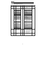
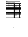
Toshiba 3-Series ASD Protocol...........................................................66
16.7.1
Command Parameters ...............................................................67
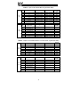
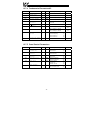
16.7.2
Monitor Parameters ....................................................................68
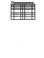
16.7.3
Fundamental Parameters #1 ......................................................72
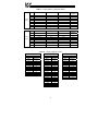
16.7.4
Fundamental Parameters #2 ......................................................73
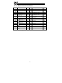
16.7.5
Panel Control Parameters ..........................................................73
16.7.6
Terminal Selection Parameters ..................................................74
16.7.7
Special Control Parameters........................................................78
16.7.8
Frequency Setting Parameters ...................................................79
16.7.9
Protection Function Parameters .................................................82
16.7.10
Pattern Run Control Parameters ................................................84
16.7.11
Feedback Control Parameters....................................................87
16.7.12
Communication Setting Parameters ...........................................88
16.7.13
AM/FM Terminal Adjustment Parameters...................................89
16.7.14
Utility Parameters .......................................................................90
16.7.15
Motor Rating Parameters ...........................................................92
16.7.16
Inverter Fault Codes ...................................................................93
17.
Firmware Updates...................................................................95
17.1
Requirements......................................................................................95
17.2
Connection ..........................................................................................95
17.3
Using the RFU Utility ...........................................................................96
17.3.1
Required Files ............................................................................96
17.3.2
First-Time Configuration .............................................................96
17.3.3
Transmitting Firmware Files .......................................................97
17.4
Wrap-Up..............................................................................................99
18.
Notes ......................................................................................100
6
1. The Network Gateway Series Concept
The ETH-200 is a member of the ICC Network Gateway Series product family.
Members of this family are designed to provide a uniform interface,
configuration and application experience. This commonality reduces the user’s
learning curve, reducing commissioning time while simplifying support. The
ETH-200 provides simultaneous support for many different communication
protocols, allowing complex interchanges of data between otherwise
incompatible networks.
The heart of the Network Gateway Series concept is an element called the
“point database”. The point database is entirely user-configurable, and
provides the mapping information that allows requests from the various
supported networks to be interpreted and stored in a common format. This
allows data to be routed from any supported network to any other supported
network.
Additionally, the point database provides the added benefit of “data mirroring”,
whereby current copies of point values (populated by a “source port”
designation) are maintained locally within the gateway itself. This greatly
reduces the request-to-response latency times on the various networks, as
requests (read or write) can be entirely serviced locally, thereby eliminating the
time required to execute a secondary transaction on a different network.
When properly configured, the gateway will become essentially “transparent” on
the networks, and the various network devices can engage in seamless dialogs
with each other.
7
2. Feature Summary
Ethernet Port
IEEE 802.3 10/100BaseT Ethernet compliant. Shielded RJ45 connector
accepts standard CAT5-type 8-conductor unshielded twisted-pair (UTP) patch
cables. Supports multiple simultaneous protocols.
RS485 Ports
Two half-duplex 2-wire RS485 ports (A / B / Signal Ground / Shield). These
ports allow a selection of various master and slave protocols.
RS232 Port
One RS232 port that can be used to configure the unit, update the internal
firmware, upload/download files or act as a control protocol port.
Toshiba ASD Ports
Three common serial (aka logic level) ports for connection of Toshiba 7-series,
9-series, 11-series or VF-nC1 ASDs. ASD connections use the same standard
RJ45 style 8-conductor UTP patch cables: any standard CAT5 Ethernet cable
(found in most electronics stores) 5 meters or less in length can be used. ASD
connections are automatically established and continuously monitored: no
drive configuration needs to be performed to connect the unit to the drives.
Just plug it in – it’s that simple.
Power Supply
When connected to Toshiba ASDs via the ASD1 / ASD2 / ASD3 ports, can be
either powered directly from the attached ASDs, or from the auxiliary power
(“AUX PWR”) input jack. All other non-Toshiba applications require the use of
the AUX PWR input to supply power to the unit. When more than one power
source is connected, the unit will draw its control power from the source with
the highest supply voltage.
Supported Protocols
•
•
•
•
•
•
•
•
Modbus RTU (RS485 master & slave)
Modbus RTU (RS232 master & slave)
Toshiba ASD (common serial master)
Toshiba ASD (RS485 master)
Toshiba 3-series ASD (RS232 master)
Modbus TCP/IP (slave)
Ethernet/IP (server)
Mitsubishi 500-series & 700-series ASD (RS485 master) (also used by
MGI Technologies, Inc. ASDs)
New network drivers are continuously being added, and can be downloaded for
free from our web site.
8
Text-Based Console Configuration
Basic unit configuration is performed via a text-based console interface,
available locally over the RS232 port via a standard PC terminal program such
as Microsoft Windows HyperTerminal®, or over Ethernet via a Telnet session.
The unit also provides initial configuration access via ICMP (“ping”)
configuration.
Macromedia® Flash-Enabled Embedded Web Server
Advanced unit configuration and point monitoring/control are also provided via
an embedded web server using the HTTP protocol. The unit’s web server
feature provides direct data access and control via standard web browsers such
as Microsoft Internet Explorer and Netscape Navigator. The latest version of
Macromedia Flash Player browser plug-in is required.
Configuration File Upload/Download
A unit’s configuration can be uploaded from / downloaded to a PC, which
provides the capability for PC-based file backup and easy configuration copying
to multiple units. Sample configuration files and related documentation can
also be downloaded from our web site, uploaded to a unit, and custom-modified
to suit a specific application.
Network Timeout Action
A per-port and per-point 2-level configurable network timeout action can be
programmed that allows each internal point to have its own unique “fail-safe”
condition in the event of a network interruption.
Indicators
•
•
•
•
•
•
•
1 green “LNK” LED that is on whenever a valid Ethernet connection is
detected.
1 green “SPD” LED that is on whenever a 100BaseT Ethernet connection
is established.
1 amber “ACT” LED that flashes whenever data is transferred across the
Ethernet network.
1 bicolor red/green “MS” LED that indicates module status information.
1 bicolor red/green “NS” LED that indicates network status information.
1 green “TX” and 1 red “RX” LED on each RS485 port.
1 green and 1 red LED on each of the Toshiba common serial ASD ports.
Refer to section 8 for more detailed information about the LED indicators and
their meanings.
Field-Upgradeable
As new firmware becomes available, the unit can be upgraded in the field by
the end-user. Refer to section 16.7 for more information.
9
Versatile Mounting Options
The unit can be panel-mounted with the included standoff kit, or snapped into
TM
existing 4” Augat SnapTrack (6TK series or equivalent). An optional
mounting kit (ICC part number 10581) is also available for DIN-rail mount
applications.
10
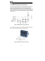
3. Installing the Gateway
The gateway’s installation procedure will vary slightly depending on the chosen
mounting method and the networks that will be used.
3.1 Mounting
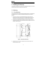
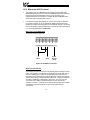
3.1.1 Panel Mounting
The included standoff kit allows for panel mounting of the unit. The standoff kit
is comprised of four 1” aluminum male/female standoffs and four #6 lock
washers.
1.
Remove one of the four cover standoff retention screws and its lock
washer from the bottom side of the unit. DO NOT dispose of this screw
and washer, as they will be used later to mount the unit to the panel.
2.
Install one of the male/female standoffs and a #6 lock washer from the
standoff kit through the unit’s circuit board and into the bottom of the cover
standoff. Refer to Figure 1.
gateway unit
panel
lock washers
lock washers
and screws
from step 1
aluminum standoffs
Figure 1: Standoff Kit Installation
3.
Repeat steps 1 and 2 above to replace each of the three other cover
standoff retention screws.
11
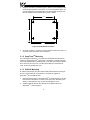
4.
Using the dimensions provided in Figure 2, drill four 0.150” diameter holes
at the specified locations on the panel. As a convenient pattern guide, the
unit with attached mounting standoffs can be held against the panel, and
the four standoff locations marked with a pencil or scribe.
3.5 IN
2.9 IN
4.0 IN
4.0 IN
Figure 2: Standoff Hole Placement
5.
As shown in Figure 1, use the four screws and lock washers from step 1 to
mount the unit from the back side of the panel.
3.1.2 SnapTrackTM Mounting
The unit footprint measures 4” x 4” square, and is designed to fit directly into
existing 4” Augat SnapTrackTM (6TK series or equivalent). Carefully insert the
unit into the SnapTrackTM by pressing firmly on the pan head screws located at
the 4 corners of the unit’s cover. DO NOT press directly on the aluminum
cover, as this may damage the cover.
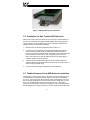
3.1.3 DIN Rail Mounting
An optional mounting kit (ICC part number 10581) allows DIN rail mounting of
the unit. The mounting kit is comprised of a 4” section of Augat 6TK
SnapTrackTM and two DIN rail clips.
1.
Carefully insert the unit into the SnapTrackTM by pressing firmly on the pan
head screws located at the 4 corners of the unit’s cover. DO NOT press
directly on the aluminum cover, as this may damage the cover.
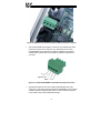
2.
Install the DIN rail clips into the openings on the bottom side of the
SnapTrackTM. Refer to Figure 3.
12
Figure 3: DIN Rail Mounting Kit Installation
3.2 Installation for Non-Toshiba ASD Networks
Note that in order to power the unit when not connecting to Toshiba ASDs via
the common serial ports, the optional 120VAC/9VDC power supply (ICC part
number 10456) or a user-supplied power source meeting the requirements
outlined in section 10 must also be installed.
1.
Mount the unit via the desired method (refer to section 3.1).
2.
Connect the various networks to their respective plugs/terminal blocks.
Ensure that any terminal blocks are fully seated into their respective
headers, and route the network cables such that they are located well away
from any electrical noise sources, such as ASD input power or motor
wiring. Also take care to route all cables away from any sharp edges or
positions where they may be pinched.
3.
Take a moment to verify that the gateway and all network cables have
sufficient clearance from electrical noise sources such as drives, motors, or
power-carrying electrical wiring.
4.
Connect the power supply to the gateway’s “AUX PWR” jack.
3.3 Toshiba Common Serial ASD Network Installation
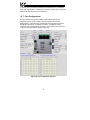
The gateway connects to each drive via the drive’s common serial (logic level)
communication port, typically located on either the main drive control board
(G7, S11), on the front of the drive enclosure under a small snap-on cover (A7,
S9), on the right-hand side of the drive enclosure under a small snap-on cover
(S7), or on the bottom side of the drive enclosure (VF-nC1). Although in
general no drive parameters need to be configured in order to use the gateway,
it is advantageous to check that the drive’s common serial communication data
13
rate is set to its maximum speed. Because the gateway will communicate to
each drive only at the drive’s configured data rate, this will provide the fastest
response time for drive-to-network data transfers. For information on checking
the drive’s common serial communication data rate, refer to the appropriate
manual supplied with your drive.
Note that the common serial communication parameters of each drive are
handled independently by the gateway, which means that different drive
families may be connected to different channels of the unit in any combination,
and that the drives connected to each channel may simultaneously
communicate to the unit at completely different baud rates, parity settings, etc.
Drives can be connected to the gateway on any ASD channel in any order or
combination. When more than one drive is connected to the unit, or if the
optional auxiliary power supply is used, the gateway will draw its control power
from the source with the highest power supply voltage.
Installation of the gateway should only be performed by a qualified technician
familiar with the maintenance and operation of the connected drives. To install
the gateway, complete the steps outlined in the following sections related to
your specific drive.
3.3.1 Installation for G7 ASDs
1.
Mount the unit via the desired method (refer to section 3.1).
2.
CAUTION! Verify that all input power sources to the drives to
be connected have been turned OFF and are locked and tagged out.
3.
DANGER!
Wait at least 5 minutes for the drive’s
electrolytic capacitors to discharge before proceeding to the next step. Do
not touch any internal parts with power applied to the drive, or for at
least 5 minutes after power to the drive has been removed. A hazard
exists temporarily for electrical shock even if the source power has
been removed. Verify that the CHARGE LED has gone out before
continuing the installation process.
4.
Remove the drive’s front cover / open the drive’s cabinet door (refer to the
appropriate drive manual for instructions how to do this).
5.
The drive’s LCD panel (also called the “Electronic Operator Interface” or
“EOI”) can communicate with the drive via either the RS485/RS232
channel (CNU1/CNU1A) or the common serial channel (CNU2/CNU2A).
Because the gateway uses the common serial channel, the LCD panel
must be configured to use the RS485/RS232 channel. If the drive to be
connected is currently using CNU2 (on the drive control board) and
CNU2A (on the LCD panel), then this connection must first be switched
over to CNU1 (on the drive control board) and CNU1A (on the LCD panel).
14
Refer to Toshiba’s documentation for any precautions or notices regarding
this connection change. If the LCD panel is already connected via the
RS485/RS232 channel, then no change is required.
6.
Configure the drive’s LCD panel to communicate via the RS485/RS232
channel by setting parameter ”Communication Setting
Parameters...Communication Settings...Select LCD Port
Connection” to “RS485/232 serial”.
7.
Connect the drive’s common serial communication port (CNU2) to one of
the ASD channels of the gateway with the communication cable
(communication cable is not included with the gateway kit). When
choosing cables for this connection, standard 24 AWG category 5 (CAT5)
unshielded twisted-pair (UTP) 8-conductor cables found in Ethernet
networks in most office environments can be used. The maximum
allowable length for these cables is 5 meters. Although there are many
varieties and styles of CAT5 UTP cables available, ICC strongly
recommends using only high-quality cables from reputable manufacturers
to guarantee optimal noise immunity and cable longevity. Ensure that each
end of the cable is fully seated into the modular connectors, and route the
cable such that it is located well away from any drive input power or motor
wiring. Also take care to route the cable away from any sharp edges or
positions where it may be pinched.
8.
Reinstall the drive’s front cover / close the drive’s cabinet door.
9.
Repeat steps 2-8 to connect other drive(s) as needed.
10. Connect the other various networks to their respective plugs/terminal
blocks. Ensure that any terminal blocks are fully seated into their
respective headers, and route the network cables such that they are
located well away from any electrical noise sources, such as ASD input
power or motor wiring. Also take care to route all cables away from any
sharp edges or positions where they may be pinched.
11. If an auxiliary power supply is going to be used, connect it to the gateway’s
“AUX PWR” jack.
12. Take a moment to verify that the gateway and all network cables have
sufficient clearance from drives, motors, or power-carrying electrical wiring.
13. Turn the power sources to all connected drives ON, and verify that the
drives function properly. If the drives do not appear to power up, or do not
function properly, immediately turn power OFF. Repeat steps 2 and 3 to
remove all power from the drives. Then, verify all connections. Contact
ICC or your local Toshiba representative for assistance if the problem
persists.
15
3.3.2 Installation for S7, S9, S11, A7 and VF-nC1 ASDs
1.
Mount the unit via the desired method (refer to section 3.1).
2.
CAUTION! Verify that all input power sources to the drives to
be connected have been turned OFF and are locked and tagged out.
3.
DANGER!
Wait at least 5 minutes for the drive’s
electrolytic capacitors to discharge before proceeding to the next step. Do
not touch any internal parts with power applied to the drive, or for at
least 5 minutes after power to the drive has been removed. A hazard
exists temporarily for electrical shock even if the source power has
been removed. Verify that the CHARGE LED has gone out before
continuing the installation process.
4.
Remove the drive’s common serial communication port cover if it has one
(refer to the appropriate drive manual for instructions how to do this). Do
not discard this cover, as it should be reinstalled to minimize contamination
of the port’s electrical contacts if the gateway is ever disconnected from the
drive.
5.
Connect the drive’s common serial communication port to one of the ASD
channels of the gateway with the communication cable (communication
cable is not included with the gateway kit). When choosing cables for this
connection, standard 24 AWG category 5 (CAT5) unshielded twisted-pair
(UTP) 8-conductor cables found in Ethernet networks in most office
environments can be used. The maximum allowable length for these
cables is 5 meters. Although there are many varieties and styles of CAT5
UTP cables available, ICC strongly recommends using only high-quality
cables from reputable manufacturers to guarantee optimal noise immunity
and cable longevity. Ensure that each end of the cable is fully seated into
the modular connectors, and route the cable such that it is located well
away from any drive input power or motor wiring. Also take care to route
the cable away from any sharp edges or positions where it may be
pinched.
6.
Repeat steps 2-5 to connect other drive(s) as needed.
7.
Connect the other various networks to their respective plugs/terminal
blocks. Ensure that any terminal blocks are fully seated into their
respective headers, and route the network cables such that they are
located well away from any electrical noise sources, such as ASD input
power or motor wiring. Also take care to route all cables away from any
sharp edges or positions where they may be pinched.
8.
If an auxiliary power supply is going to be used, connect it to the gateway’s
“AUX PWR” jack.
9.
Take a moment to verify that the gateway and all network cables have
sufficient clearance from drives, motors, or power-carrying electrical wiring.
16
10. Turn the power sources to all connected drives ON, and verify that the
drives function properly. If the drives do not appear to power up, or do not
function properly, immediately turn power OFF. Repeat steps 2 and 3 to
remove all power from the drives. Then, verify all connections. Contact
ICC or your local Toshiba representative for assistance if the problem
persists.
17
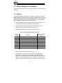
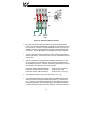
4. RS485 Port Electrical Interfaces
In order to ensure appropriate network conditions (signal voltage levels, etc.)
when using the gateway’s RS485 ports, some knowledge of the network
interface circuitry is required. Refer to Figure 4 for a simplified network
schematic of the RS485 interface circuitry. Note that the “Shield” terminal has
no internal connection: its purpose is simply to provide a cable shield chaining
location between devices. The shield is then typically connected to ground at
one location only.
Figure 4: RS485 Interface Circuitry Schematic
Figure 5 details the specific network connections to the RS485 terminal block.
This connection scheme applies equally to both RS485 ports.
A
B
Signal Ground
Shield
Figure 5: RS485 Terminal Block Connections
18
5. Environmental Specifications
Item
Specification
Operating Environment
Indoors, less than 1000m above sea level, do not
expose to direct sunlight or corrosive / explosive
gasses
Operating Temperature
-10 ∼ +50°C (+14 ∼ +122°F)
Storage Temperature
-40 ∼ +85°C (-40 ∼ +185°F)
Relative Humidity
20% ∼ 90% (without condensation)
Vibration
2
5.9m/s {0.6G} or less (10 ∼ 55Hz)
Grounding
Cooling Method
Non-isolated, referenced to power source ground
Self-cooled
19
6. Maintenance and Inspection
Preventive maintenance and inspection is required to maintain the gateway in
its optimal condition, and to ensure a long operational lifetime. Depending on
usage and operating conditions, perform a periodic inspection once every three
to six months. Before starting inspections, disconnect all power sources.
Inspection Points
•
Check that the network cable(s) are properly terminated in the terminal
block(s), and ensure that pluggable terminal blocks are fully seated in their
headers. Reseat if necessary.
•
Check that there are no defects in any attached wire terminal crimp points.
Visually check that the crimp points are not damaged or loose.
•
Visually check all wiring and cables for damage. Replace as necessary.
•
Clean off any accumulated dust and dirt.
•
If use of the gateway is discontinued for extended periods of time, apply
power at least once every two years and confirm that the unit still functions
properly.
•
Do not perform hi-pot tests on the gateway, as they may damage the unit.
Please pay close attention to all periodic inspection points and maintain a good
operating environment.
20
7. Storage and Warranty
7.1 Storage
Observe the following points when the gateway is not used immediately after
purchase or when it is not used for an extended period of time.
•
Avoid storing the unit in places that are hot or humid, or that contain large
quantities of dust or metallic dust. Store the unit in a well-ventilated
location.
•
When not using the unit for an extended period of time, apply power at
least once every two years and confirm that it still functions properly.
7.2 Warranty
The gateway is covered under warranty by ICC, Inc. for a period of 12 months
from the date of installation, but not to exceed 18 months from the date of
shipment from the factory. For further warranty or service information, please
contact Industrial Control Communications, Inc. or your local distributor.
21
8. LED Indicators
The gateway contains several different LED indicators, each of which conveys
important information about the status of the unit and connected networks.
These LEDs and their functions are summarized here.
8.1 Toshiba ASD Common Serial Port Indicators
Each Toshiba ASD common serial port RJ45 connector has two LEDs
positioned immediately above them (1 green and 1 red).
Green LED ...... Indicates “drive link”. Solid green when a logical connection
exists with the attached drive (i.e. the gateway is reading data
from the drive).
Red LED.......... Data write. Flashes briefly when data is written to the drive
from the point database.
8.2 Ethernet Port Indicators
The Ethernet Port RJ45 connector has three LEDs positioned immediately to
the left of it.
SPD...... SPeeD: solid green whenever a 100BaseT Ethernet connection is
established.
LNK ...... LiNK: solid green whenever a valid Ethernet connection is detected.
ACT ...... ACTivity: flashes amber whenever network activity is detected.
8.3 RS485 Port Indicators
Each RS485 port has one red and one green LED situated next to its
respective terminal block.
Green LED ...... Lights when the gateway is transmitting data on the port.
Red LED.......... Lights when the gateway is receiving data on the port (note that
this does not indicate the validity of the data with respect to a
particular protocol: only that data exists and is being detected.)
8.4 Ethernet/IP Status Indicators
One Module Status (“MS”) LED and Network Status (“NS”) LED exists. These
bicolor red/green indicators conform to the prescribed behavior as dictated in
the Ethernet/IP specification, Volume 2, Chapter 9.
22
9. Configuration Switches
There are two configuration DIP switches (marked “CFG”) located on the unit
near the RS232 port.
Switch #1 .........Firmware update switch. Place in “OFF” position for normal
operation, and in the “ON” position only when new firmware is
to be downloaded to the unit. Refer to section 17 for more
information.
Switch #2 .........RS232 port selection switch. When “OFF” at unit startup, the
RS232 port will act as the serial console, regardless of the
port’s configuration as indicated on the web interface (refer to
section 14.1 for more information on the serial console). When
“ON” at unit startup, the RS232 port carries whatever protocol
was assigned to it via the web interface. Note that the state of
this switch is only detected when the gateway boots up.
10. Auxiliary Power Supply
The ICC part #10456 120VAC/9VDC power supply can be used to power the
unit via the AUX PWR input. If providing your own auxiliary power supply,
ensure that it adheres to the following specifications:
+
Connection diagram................
Voltage rating.......................... 9 - 40VDC
Current rating.......................... 500mA (@9VDC)
The gateway’s AUX PWR input uses the CUI, Inc. PJ-002A (2.1mm x 5.5mm)
or equivalent DC power jack, which mates with the PP-002A (2.1mm x 5.5mm)
or equivalent power plug.
11. Internal Battery
The interface has an internal coin-cell type battery that is currently only used to
support the real-time clock when the unit is unpowered. This battery is
designed to last the lifetime of the product under normal use. However, if the
interface is left unpowered for several years, the battery may become
exhausted. If the battery becomes discharged, it can be replaced by removing
all power sources from the gateway according to the required safety
procedures, and then carefully popping out the discharged battery and
replacing it with a Panasonic BR1632 or equivalent component.
23
12. Unit Configuration Concepts
12.1 Port and Protocol Configuration
Each of the communication ports (or, in the case of the Ethernet port, the
protocols) can be individually configured or enabled/disabled. It is important to
note that the ports (and Ethernet protocols) function independent of one
another, and can operate simultaneously. For example, a Modbus TCP/IP
request, Modbus RTU slave request on RS485A, and an ASD1 request can
simultaneously access the same internal point.
Although each communication port can be configured via the web interface,
their configuration selections vary slightly. The Toshiba ASD common serial
ports have a simple enable/disable selection. The RS232 and RS485 ports can
be disabled, or can have one of a selection of control protocols assigned to
them. The Ethernet port can by definition carry multiple control protocols
simultaneously, and therefore each protocol it supports can be individually
enabled or disabled.
Along with the protocol selection for the RS232/RS485 ports, each of these
ports also has a corresponding baudrate, parity, address assignment and
timeout time assignment. Note that not all assignable protocols support the
same range of configuration options: therefore be sure to assign a valid entry in
all cases (for example, a Modbus RTU slave’s “address” assignment must be in
the range 1-247 to comply with the Modbus specification). Also note that
certain protocols may not make use of all available configuration options (e.g.
certain protocols operate only at one specified baudrate regardless of the
“baudrate” selection value). The protocol-specific sections of this manual will
document these cases.
Similarly, each of the Ethernet protocols has its own unique configuration
attributes, such as Ethernet/IP’s assembly object member lists and Modbus
TCP/IP’s timeout assignments.
12.2 Timeout Configuration
The gateway’s points can be configured to perform a specific set of actions
when primary communications are lost on one or more of its various networks.
This allows each point to have its own unique “fail-safe” condition in the event
of a network interruption. There are three separate elements (four in the case
of Modbus TCP/IP) that define the network timeout behavior:
•
•
•
•
A port’s network timeout time
A point’s “Timeout Enable” selection
A point’s “Timeout Value” setting
For Modbus TCP/IP, a “Master IP” address designation
24
The timeout time adjustment range depends on the port. For the RS485 and
RS232 ports, the time is adjustable in 1s increments from 0 to 500s. For the
Modbus TCP/IP protocol, the time is adjustable in 1ms increments from 500ms30000ms (0.5s-30.0s).
The default timeout time in all cases is 0, which disables network timeout
handling. When nonzero, timeout processing does not begin until after a valid
network packet has been received by the unit on that port. In the case of
Modbus TCP/IP, a “timeout” event will only be deemed to have occurred when
a communication lapse or abnormal socket error takes place with the specific
client device designated by the “Master IP” address: a communication lapse or
abnormal socket error with any other client will not result in a timeout event.
When the timeout time is nonzero and a communication interruption is
detected, the timeout enable selections for each point are inspected. Those
points that are found to have their timeout enable selections set to “enabled”
will then have their configured timeout values automatically written to their
assigned “source port” objects. This mechanism provides for a flexible set of
device failsafe conditions to be established on a point-by-point basis.
12.3 Point Configuration
As mentioned in section 1, the Network Gateway Series concept revolves
around a central “point database”, containing the value and access
characteristics for each network. With respect to the Network Gateway Series,
a “point” is simply an object that defines some sort of network access, mapping
and configuration data, as well as a single “value” attribute that can be read
from or written to by various communication ports or protocols.
The only restriction placed on this “central clearinghouse” concept is that only
one port can autonomously update the point’s value, “mirroring” its designated
object for other protocols to access. What this means is that although any
protocol can read from or write to a point’s internal value, most of the time that
point’s value will simply be mirroring a remote data object that resides on one of
the gateway’s subnets. The selection of what a specific point is to mirror is
performed via its “source port” selection.
For example, a point may be configured to contain Toshiba ASD parameter
mapping and Modbus master ID and register mapping information. However,
because both of these protocols act as “master” protocols, only one of them
can be allowed to continuously update the point’s value. If both master
protocols could simultaneously update the point’s internal value, it would
erratically alternate back and forth between the values designated by the
Toshiba parameter and Modbus register objects. Any “slave” protocol (Modbus
RTU slave, Metasys N2, Ethernet/IP etc.) can read from or write to a point at
any time, but only the protocol designated by the point’s “source port”
25
assignment will autonomously update the point’s value independent of any
other protocol traffic.
The “source port” designation also determines where a new point value will be
written to when a “slave” protocol writes a new value to the point. For example,
if an Ethernet/IP connection consumes new data that changes the value of a
point, how do we know where this new value will exit the gateway to arrive at its
final destination? The answer is that any new point values written by “slave”
protocols will generate “write” transactions only on the “source port”.
This concept may best be further explained by way of a representative
scenario. For example, let’s assume that the gateway’s RS485A port has been
designated to be a Modbus Master. Let’s further assume that the “Modbus
Master” portion of point #5 indicates a “Source ID” value of 8 and “Register”
value of 14, and that point #5’s “Source Port” selection is set to “RS485A”.
What this means is that independent of any other gateway traffic, point #5 will
continuously attempt to update its internal value by making requests to the
RS485A port. And, because the RS485A port has been designated as a
Modbus Master, then the “Modbus Master” portion of point #5’s configuration
will be referenced by the update task, and point #5’s value will therefore always
be mirroring the value of (holding or input, depending on the configuration)
register #14 of remote Modbus station address #8 connected to the Modbus
subnet attached to the gateway’s RS485A port. Perhaps register #14 of
Modbus station address #8 is a monitor item, indicating the pressure in
compressor tank. Whenever the tank’s pressure changes, therefore, the value
of point #5 will automatically update to reflect the new value read from the
remote device. Once the tank’s pressure reading has been brought into the
gateway, it can then be retrieved by any protocol (or ALL the protocols)
currently assigned to the gateway’s other communication ports.
As a modification to the previous example, let’s assume this time that register
#14 of Modbus remote station address #8 is the speed command of a conveyor
belt. In this case, point #5 of the gateway will be mirroring the current speed
command of the conveyor, in a similar fashion to how it previously mirrored the
compressor tank’s pressure. This time, however, the speed command
represents something that can also be written to. Therefore, let’s assume that
point #5 has been included in the output assembly member list of the
Ethernet/IP protocol, and that a new data value is consumed by an Ethernet/IP
connection object that causes the value of point #5 to be changed. In this case,
this new point value will automatically cause a “write holding register”
transaction to occur on the RS485A Modbus master port, updating the value of
register #14 on remote Modbus station #8, causing the conveyor to accelerate
(or decelerate) to the new speed.
Note that it is also perfectly acceptable to have a point’s “source port” assigned
to “no source”. All this means that this point will not be autonomously updated
(i.e. that it will not automatically mirror anything.) In a sense, it will simply be
“scratchpad memory” that the various ports and protocols can use to exchange
information among themselves. For example, a Modbus TCP/IP write
transaction could update the value of such a point, which then can be inserted
26
into the produced assembly data of an Ethernet/IP connection, causing the
gateway to act as a Modbus TCP/IP –to- Ethernet/IP router, while
simultaneously performing its other network functions.
Although the various configuration possibilities may seem overwhelming at first,
it is clear that the gateway can perform powerful and flexible routing algorithms.
Through configuration experience, the “in” and “out” data flows will become
more clear.
12.4 General Configuration Procedure
Now that we have had a brief tutorial on port and point configuration, we can
proceed on to how these elements fit into the overall configuration procedure.
The general configuration procedure steps can be summarized as follows:
1.
2.
3.
4.
5.
6.
Assign the initial Ethernet configuration via either the ARP ping
method or console configuration method.
Access the embedded web server’s configuration page via a web
browser.
Assign (or enable/disable) the desired protocols and their
characteristics to the specific communication ports.
Perform the desired per-protocol mapping and definition assignments
for each point, including the name, timeout and “source port”
assignments.
Submit the changes to the gateway, which will update its internal
configuration file and reboot the unit.
Download a copy of the unit’s configuration file to your PC for backup
purposes
Of course, it is possible to simplify or even eliminate some of these steps by
starting your configuration from a pre-existing point database file (either
downloaded from the internet or previously-created by the user), and then
simply modifying those elements necessary to match your application.
27
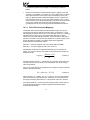
13. Initial Ethernet Configuration
The gateway typically requires configuration prior to communicating on an
Ethernet network. This fundamental configuration is achieved via one of two
possible methods: using ICMP (“ping”) configuration via the Address Resolution
Protocol (ARP), or via a text-based console interface, accessible over the
RS232 serial channel and a telnet interface. The following are the factory-set
values of the most important Ethernet parameters:
IP Address.........................192.168.1.100
Subnet Mask .....................255.255.255.0
Default Gateway................192.168.1.2
If these parameters are not compatible with your network settings, they will
need to be modified.
13.1 ARP Method
The IP address can be changed remotely by using the Address Resolution
Protocol (ARP). This is performed by adding a static entry into a PC’s ARP
cache table, which stores the associations between a device’s IP and physical
(MAC) addresses. The unit is then “pinged” from a command prompt (MS
DOS™ window) to assign the new IP address to it. Below is an example of the
commands used to change the unit’s IP address:
arp -s <IP address> <MAC address>
ping <IP address>
arp -d <IP address>
The initial “arp –s” command adds a static association between the unit’s MAC
address and the desired IP address to the PC’s ARP table. When the ping
command is executed with the IP address as an argument, the PC sends this
information to the unit indicated by the associated MAC address. The unit then
detects that it was addressed with the correct MAC address and adopts the IP
address indicated in the ICMP “ping” packet. The optional “arp –d” command
then removes the static route from the PC’s ARP table.
The unit’s MAC address is printed on a label located to the left of the Ethernet
jack on the unit’s cover. An example of setting a unit’s IP address to
192.168.16.110 would look like:
arp -s 192.168.16.110 00-90-C2-C0-29-8B
ping 192.168.16.110
arp –d 192.168.16.110
Forcing the unit to adopt the new IP address completes only half of the ARP
configuration process. In addition to the IP address being changed, the unit
also automatically configures its subnet mask to 255.255.255.255. This setting
28
essentially allows only the computer that issued the ping command to
communicate with the unit. From this computer, then, the user must also
access the unit’s web page via a web browser, or its console via a telnet
session, in order to write the IP address to the filesystem. Until the new IP
address is written to the filesystem, the IP address change is only temporary. If
the unit loses power or is otherwise reset prior to submitting/setting the new IP
address, the previous IP address and subnet mask settings will return.
Note that if the IP address is to be modified via the unit’s web page, that
network elements such as HTTP proxy servers may relay the web page request
for the configuring computer. The unit, seeing the HTTP request from a
computer other than that which performed the initial “ping”, will ignore such a
request. Therefore, be sure to bypass or disable any proxy servers at least
temporarily when using this configuration method.
For security reasons, once the ARP method of configuration has been
successfully completed (i.e. the IP address has been written to the filesystem),
the ARP method of configuration will be disabled, and all future attempts at
using this method will be ignored by the unit. It is possible, however, to reenable the ARP method via a console command (refer to section 14.3).
13.2 Console Method
The console method of configuration is achieved via a text-based console
interface, accessible over the RS232 port and a telnet interface. The RS232
console is accessed by connecting the port to a computer’s serial (COM) port,
and then running a terminal emulation program, such as Windows®
HyperTerminal. If the ARP method of initial configuration is not used, then the
RS232 console must be accessed. More information about the console
interface and its commands can be found in section 14.
29
14. Console Access
14.1 RS232
The console is accessible via an RS232 interface for direct connection to a
computer’s serial (COM) port. This is performed by connecting the unit’s
RS232 port to the computer’s serial port via a standard straight-thru serial
cable. Unless the ARP ping configuration method is used, this will typically be
the initial configuration channel, as the telnet and web browser interfaces can
only be accessed once the network parameters have already been established
and the device is communicating on the Ethernet network.
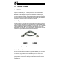
14.1.1 Requirements
All that is needed is a computer with a serial (COM) port containing some sort
of communications software (such as HyperTerminal, included with Microsoft
Windows operating systems) and a straight-thru serial cable, such as the Belkin
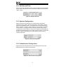
6’ serial extension cable (Belkin part #F2N209-06). Refer to Figure 6 for a
representative example cable. Any communications software and PC will work,
provided they support ASCII communications at 38.4kbaud.
Figure 6: A Typical Serial Extension Cable
14.1.2 Connection
Connect one end of the serial cable to the gateway’s RS232 port, and connect
the other end to the computer’s serial port. Make sure that CFG DIP switch #2
is in the “OFF” (left) position to force the RS232 port to act as the serial
console. If the unit is currently using the RS232 port for control protocol
communication, then it must be rebooted (powered down and then back up
again) with CFG switch #2 in the OFF position to enable the serial console on
the RS232 port.
30
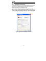
14.1.3 Application Configuration
As previously mentioned, any PC communication software and PC serial port
can be used. The software configuration example given here will be for
Windows HyperTerminal communicating via COM1.
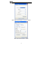
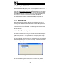
Figure 7 shows the “Connect To” tab of the properties window for COM1.
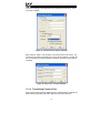
Figure 8 shows the window that appears when “Configure” is selected in the
“Connect To” tab. Figure 9 shows the “Settings” tab of the properties window.
Most of these settings are their default values: usually the only change needed
is the “Bits per second” setting shown in Figure 8.
Figure 7: HyperTerminal Properties…Connect To
31
Figure 8: HyperTerminal Properties…Connect To…Configure
Figure 9: HyperTerminal Properties…Settings
32
14.2 Telnet
The console is also accessible via a Telnet interface for remote administration
over Ethernet once the unit is communicating on the network. The Telnet
console uses well-known port 23. Note that although only 1 telnet console
session can be active at any given time, the telnet console and RS232 console
operate independently and can be used simultaneously.
14.2.1 Requirements
All that is needed is a computer with telnet software that can access the
gateway over the Ethernet network. Telnet software is typically included as a
standard component of Microsoft Windows and other PC operating systems.
14.2.2 Connection
No special connections are required, other than the PC running the Telnet
application must be able to access the gateway to be configured.
14.2.3 Application Configuration
Although any software vendor’s Telnet client application can be used, the
configuration example given here will use the Microsoft Windows Telnet
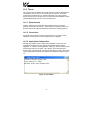
application. To start the Telnet application, simply type “telnet” at either a DOS
(command) prompt or in the “Start…Run” window. Once the telnet client
screen opens, the target device can be accessed simply by typing “open” at the
Telnet prompt with the gateway’s IP address as an argument. Refer to Figure
10.
Figure 10: Telnet Menu
33
14.3 Command Overview
The console provides standard access and configuration methods for the
various network parameters and configurations supported by the gateway. This
section will present an overview of the supported console commands.
It is important to note that unless otherwise indicated, each of these commands
will become effective immediately after it has been successfully entered. This
may have several repercussions; for example, if you change the IP address of
the device via the Telnet console, then you will lose the telnet connection to the
device (as it was a connection to the old IP address) and therefore must reconnect to the console if you wish to continue changing parameters. Also note
that the console commands are not case-sensitive.
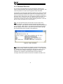
Help: This command shows the console version and an overview of all
available commands. As indicated in the returned help information, typing
“Help <command>” with a specific command will return help information specific
to that command. Refer to Figure 11 for the help command output via Telnet.
All further display screens shown in this section will be from Telnet, although
they will look identical when accessed via the RS232 port.
Figure 11: "Help" Command
Set: The “Set” command actually encompasses several subcommands, each
of which allows setting a different configuration parameter. To set a parameter,
two arguments are required: the parameter’s name and the value to set it to.
Figure 12 shows an example of changing the IP address of a device to
192.168.16.120. After this command is entered, the device will then
reconfigure itself to allow network access via the IP address 192.168.16.120.
34
Figure 12: "Set" Command Overview and Implementation
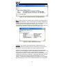
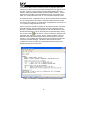
Show: Figure 13 shows an example of this command, which displays current
configuration information. Some of this information (IP Address, Netmask and
Gateway) is configurable via the “set” command. The “Firmware Version” field
indicates the unit’s current application firmware version. The “Ping
Configuration” field indicates whether or not the ability to remotely configure the
unit via the ARP method is currently allowed (refer to section 13.1).
Figure 13: "Show" Command Overview
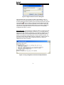
Xmodem: The “xmodem” command allows unit configuration files to be
transferred between the gateway and a PC. As Xmodem is a serial protocol,
the xmodem command only applies to the serial console (RS232 port).
Whenever unit configuration is completed, it is highly recommended that a
backup copy of the configuration file be downloaded from the unit to a PC. One
reason for this is in case it becomes necessary to restore a previous
configuration at a later time. Another reason is that it may be desirable to load
multiple units with the same configuration. Configuration files contain all point
and port settings (but not network configuration information, such as IP
address). A downloaded configuration file can be uploaded to any compatible
ETH-200, allowing the user to clone multiple units with the same configuration.
35
Two different variations of the Xmodem protocol are supported (CRC and
Checksum) for those serial communication packages that only support one or
the other. However, some programs can automatically adapt to the user’s
selection, making the specific Xmodem protocol selection arbitrary. The first
argument of the xmodem command indicates the mode, and must be set to
either “/crc” for Xmodem CRC mode, or “/cs” for Xmodem checksum mode.
As mentioned above, configuration files can be both downloaded and uploaded.
The second argument in the xmodem command indicates the action to take,
and must be set to either “/d” to download the configuration file from the unit, or
“/u” to upload a configuration file to the unit.
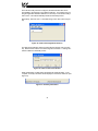
Figure 14 shows an example of initiating an Xmodem download in CRC mode.
Once the message “The ETH-200 is ready to send its configuration file via
Xmodem…Download the file now” appears, the user has 30 seconds to start
the Xmodem download. This can be performed in HyperTerminal by clicking
the “receive” button ( ) on the tool bar. Figure 15 shows the dialog box that
will appear after clicking the “receive” button. Specify the folder in which to
place the received file, select Xmodem as the receiving protocol, and click
“Receive”. One last dialog box will prompt the user to name the received file,
and then the transfer will begin. This will only take several seconds to
complete, and at the conclusion the console will indicate the status of the
transfer and return to the entry menu.
Figure 14: “Xmodem” Command Overview and Implementation
36
Figure 15: HyperTerminal receive file dialog box
When uploading a file, the procedure is similar to downloading. Enter “/u”
instead of “/d” for the action parameter of the xmodem command. Once the
xmodem upload command is entered, the user will have 30 seconds to click the
“send” button ( ) on the tool bar in HyperTerminal and initiate the Xmodem
upload transaction. Upon successful completion of the Xmodem upload, the
unit will reset, and the uploaded file will become the unit’s active configuration.
The previous configuration cannot be recovered (unless a corresponding
configuration file exists, of course).
Ping config reset: This command re-enables the ability to configure the unit’s
IP address via the ARP method (refer to section 13.1). For security reasons,
whenever the ARP method of configuration is successfully completed, the unit
disables this method, and subsequent attempts at ARP configuration will be
ignored. By entering the “ping config reset” console command, however, the
unit will once again allow the ARP method of configuration. Refer to Figure 16.
Recall that the current ARP method configuration status can always be
obtained via the “show” command.
Figure 16: "Ping Config Reset" Overview and Implementation
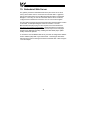
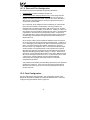
37
15. Embedded Web Server
The gateway contains an embedded web server (also known as an HTTP
server), which allows users to access the unit’s internal data in a graphical
manner with web browsers such as Microsoft Internet Explorer or Netscape
Navigator. In this way, the unit and connected devices can be monitored,
configured and controlled from across the room or from across the globe.
The ETH-200’s web pages are best viewed with either Internet Explorer version
5.x and later, or Netscape Navigator version 6.x and later. The free
Macromedia Flash player plug-in is also required, and can be obtained at
http://www.macromedia.com/go/getflash. Always ensure that you have the
latest version of the Flash player installed: if some aspect of the web pages
appears to be displayed unusually, installing the latest Flash player update
usually resolves the problem.
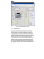
To access the unit’s embedded web server, just enter its configured IP address
into the address (URL) field of your web browser. Accessing the ETH-200’s
web page is the same as surfing the Internet’s world-wide web. Refer to Figure
17 for an example.
38
Figure 17: Embedded Web Server Interface
15.1 Authentication
For security, the ETH-200 requires valid user authentication when the web
page is accessed or the point information is modified. The authentication
request will appear as a browser popup box that will request entry of a user
name and password. The unit contains two different security realms: an
administrator realm and a user realm. Each of these realms has a different
username and password, and applies to different activities. This division of
authentication realms allows a device administrator to retain control of critical
items (such as changing a unit’s IP address or modifying point values and point
definitions) while allowing a device user with appropriate authorization to
monitor point values (i.e. observe the status of the attached network devices).
Refer to Figure 18 for a screen shot of the administrator realm authentication
dialog box, and Table 1 for initial factory-set authentication values. Note that
the username and password are case-sensitive, and that once authenticated,
the authentication will remain in effect from that point until all browser windows
are closed.
39
Figure 18: Administrator Authentication
Table 1: Initial factory-set authentication values
Realm
Username
USER
user
ADMIN
admin
Password
Blank (i.e. do not
enter a password)
Blank (i.e. do not
enter a password)
Realm Applies To
Monitoring capabilities
All change actions
15.2 Communication Status Indicators
Figure 19 shows the communication status indicators. These will blink
periodically to show the status of data communication between the web browser
and the unit.
Figure 19: Communication Status Indicators
15.3 Unit Status
Figure 20 shows the non-modifiable unit status information. This includes the
48-bit Ethernet MAC address, and the application firmware version information.
Figure 20: Unit Status
40
15.4 Set Date and Time
Figure 21 shows the submission boxes in which new date and time information
can be entered. Note that the hours are entered in military time format (0-23 =
12AM – 11PM).
Figure 21: Set Date and Time
15.5 Network Configuration
Figure 22 shows the submission boxes in which network configuration
information can be entered. Note that changing the subnet mask or default
gateway will immediately result in a momentary loss of communications: just
wait for a moment, or use the “refresh” button on your browser to re-establish
communications. Changing the unit’s IP address, however, will result in a
complete loss of communications, as the unit’s IP address will immediately be
changed from that of the page you are viewing to the new value. To reconnect,
therefore, requires transitioning to the new IP address via the browser’s
“Address” (URL) field.
Figure 22: Network Configuration
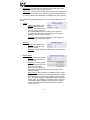
15.6 Authentication Configuration
Figure 23 shows the submission boxes used to change the user-level and
administrator-level usernames and passwords.
Figure 23: Authentication Configuration
41
To change, enter your desired username and password (max 11 characters
each), then click “Submit”. Contact ICC if you have forgotten your username or
password for instructions on how to reset them.
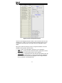
15.7 Port Configuration
The ETH-200 has eight ports (the Ethernet port actually acts like two
independent “ports”, as the control protocols it supports can be used
simultaneously). There are three Toshiba ASD common serial connections,
two RS485 connections, one RS232 connection, one Modbus TCP/IP
connection, and one Ethernet/IP connection. These various connections are
configured using the interface shown in Figure 24.
Figure 24: Port Configuration Interface
42
15.7.1 Toshiba ASD Common Serial Port Configuration
The Toshiba ASD common serial connection ports are configured by selecting
either “enabled” or “disabled” from the drop-down box. It is recommended to
disable those ports that will not have drives connected to them.
15.7.2 RS232 and RS485 Port Configuration
The RS232 and RS485 ports have the following configuration parameters:
•
Protocol: Use the drop-down box to select the desired protocol to be
attached to this port.
•
Baudrate: Use the drop-down box to select the desired network baudrate
(note that some protocols have a fixed baudrate and ignore this selection).
•
Parity: Use the drop-down box to select the desired network parity (note
that some protocols have a fixed parity and ignore this selection).
•
Address: This assigns this port a network address for the selected
protocol.
•
Timeout: Defines a timeout time (in seconds) that the port uses to identify
a network timeout. 0 = timeout disabled.
15.7.3 Modbus TCP/IP Configuration
The Modbus TCP/IP protocol has the following configuration parameters:
•
Enable/Disable: Enables or disables this protocol.
•
Master IP: Defines the IP address that the Modbus TCP/IP driver will
consider as its “master” for timeout purposes.
•
Timeout: Defines a timeout time (in milliseconds). This network timeout
only applies to network traffic originating from the configured “master IP”
address. Valid timeout times are 500ms-30000ms (0.5s-30.0s).
Because the socket timeout determination is performed on a per-socket basis,
note that a certain degree of caution must be exercised when using the network
timeout feature to avoid “nuisance” timeouts from occurring. Specifically, do
not perform inadvisable behavior such as sending a request from the master
device to an ETH-200, and then closing the socket prior to successfully
receiving the unit’s response. The reason for this is because the gateway will
then experience an error when attempting to respond via the now-closed
socket, which will immediately trigger the timeout action. Always be sure to
manage socket life cycles “gracefully”, and do not abandon outstanding
requests.
Modbus TCP/IP sockets initiated from devices other than the “master” device
use a fixed 30s timeout time, and do not perform timeout processing. This
allows devices other than the designated “master” to access the unit for
monitoring or other non-critical access purposes.
43
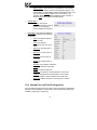
15.7.4 Ethernet/IP Port Configuration
The Ethernet/IP port has the following configuration parameters:
•
Enable/Disable: Enables or disables this protocol.
•
Produced/Consumed Assembly Member Lists: These arrays allow the
creation of custom-built assembly instances. Each box in the array is
capable of containing a point number. Because the “value” attributes of
each point are 16-bit data elements, each box represents two bytes of
consumed or produced data.
Up to 100 points can be assigned to each member list (for a total of 200
bytes of produced and/or consumed data). The array locations are
numbered 0-99, and traverse from left to right across each row, and then
increment to the left-most position on the next row. Clicking on a box in an
array toggles the point that will be referenced when class 1 connected data
is produced or consumed at that corresponding location. A blank array
entry indicates that no point is referenced at that location, which will cause
corresponding consumed data to be ignored and produced data to be a
default value of 0.
As an example, looking at the member list definitions shown in Figure 24,
we can see that each member list contains 6 defined points. Therefore, up
to 12 “meaningful” bytes of data can be both consumed and produced via
class 1 connected messages (the qualifier “meaningful” is used here
because a client may configure a class 1 connection that indicates larger
produced and/or consumed data sizes, but all unreferenced consumed
data (data after byte #12) will be ignored, and all unreferenced produced
data (also data after byte #12) will be dummy “0” values). The first word
(two bytes) of consumed data will be written to the “value” attribute of point
#3, the next two bytes to point #4 and so on. If points #3 and #4 etc. have
a “Source Port” selection defined, then this command data will
subsequently also propagate to that port and down to the point’s
configured remote device.
This example works similarly when describing the behavior of the produced
member list in Figure 24. In this case, the first 2 bytes of the produced
data will be the value of point #1, the next two bytes will be the value of
point #2 and so on.
15.8 Point Configuration
The ETH-200 supports 100 total points. The configuration of these points
determines what data is available from attached network devices. Points are
configured using the interface shown in Figure 25.
44
Figure 25: Point Configuration Interface
The list on the left displays the point number, name and current value for each
available point. Clicking on one of these locations will load the point’s current
configuration into the point box on the right, where the configuration may be
edited.
Each point contains the following common configuration attributes, which are
available in the top portion of the point box:
•
Name: This is a user description of the point, up to 16 characters.
•
Timeout En: Checking this box will allow the point to participate in timeout
processing when a port network timeout event is detected.
•
Timeout Value: This determines the value this point will default to upon the
occurrence of a network timeout. If a “Source Port” has been designated
(see below), then this value will also propagate to the configured remote
device connected to the designated port.
45
•
Source Port: This drop-down list determines the ETH-200 port that this
point will obtain its value from and write values to.
•
Edit Protocol: This drop-down list allows the selection of any of the point’s
protocol-specific attributes. Once selected, the point’s attributes related to
the chosen protocol will be displayed in the middle portion of the point box.
The available protocol-specific selections and corresponding attributes are as
follows:
•
•
•
Toshiba:
o
Address: The address of the
Toshiba ASD that this point
refers to. This address field is
only used in conjunction with
the Toshiba RS485 protocol: Toshiba common-serial port
connections are point-to-point, and therefore do not require
targeting a drive at a specific address.
o
Parameter: The Toshiba ASD parameter (in hex, 0000-FFFF)
within that drive that this point refers to.
Mitsubishi:
o
Address: The address of the
Mitsubishi or MGI drive that
this point refers to.
o
Parameter: The parameter within that drive that this point refers
to.
Modbus Master:
o
Address: The network address
of the Modbus slave that this
point refers to.
o
Register: The holding register
or input register that this point
will access. The type of
register accessed (holding or
input) will be determined on the basis of the “Read Function”
setting (see below).
o
Write Function: Allows selection of the Modbus “write” function
code that will be used to write to the designated holding register
(this setting does not apply to input registers, as they are readonly). The default setting is “Write Multiple Registers” (Modbus
function code 16). Alternatively, this setting can be changed to
“Write Single Register” (Modbus function code 06) in order to
connect to those Modbus slave devices that do not support
function code 16.
46
o
•
Modbus Slave:
o
•
Read Function: Allows selection of the Modbus “read” function
code that will be used to read from the designated register. The
default setting of “Read Holding Registers” (Modbus function code
03) will access a holding register on the remote device. By
selecting “Read Input Registers” (Modbus function code 04), a
Modbus input register will be accessed instead.
Register: The register
(accessible as either a holding
register or input register)
number assigned to this point.
Ethernet/IP: Note that these attributes
are currently unused and can therefore
be ignored.
o
Help: User defined help text,
up to 24 chars.
o
Units: User defined
engineering units text, up to 5
chars.
o
Data Type: The data type of
this point.
o
Maximum: The max value of
this point.
o
Minimum: The min value of
this point.
o
Default: The default value of
this point.
o
Multiplier: The multiplier of this point.
o
Divider: The divider of this point.
o
Offset: The offset of this point.
o
Precision: The precision, in decimal places, of this point.
o
Scaling: Checking this box tells this point to use (value x
multiplier)/divider + offset to determine its actual value.
o
Read only: Defines this point as read only when checked.
15.9 Upload Port and Point Configuration
Once all desired changes have been made to the port and point configurations,
this data must be uploaded to the ETH-200. This is performed by clicking the
“SUBMIT” button shown in Figure 26.
47
Figure 26: Port and Point Configuration Upload
Submitting the port and point configuration may require up to 1 minute to
complete, during which time a “please wait” graphic will be displayed. Once the
upload completes, the interface will return to its normal screen. However,
clicking your browser’s refresh button may be required to reestablish
communications with the ETH-200.
This process will also result in the loss of communications with all devices
connected to the ETH-200. It is important to ensure that all connected devices
are in a safe state such that loss of communications will not pose a danger to
equipment or personnel before using this feature.
15.10 Radix Selection
Figure 27 shows the radix selection buttons. These selection buttons allow
changing the point value data display and entry radix between decimal and
hexadecimal formats.
Figure 27: Radix Selection
15.11 Editing Point Values
The value of the currently selected point can be modified using the interface
shown in Figure 28. The radix of the value entered here is determined by the
radix selection described in section 15.10. Editing the point value in this
interface and selecting “SUBMIT” immediately updates the point’s value in the
unit, which will result in a write to the point’s configured “Source Port” if one is
assigned.
Figure 28: Edit Point Value Interface
48
15.12 Error Code Reference
Figure 29 shows the error code reference table, located in the bottom portion of
the point box. These error codes may appear in certain situations in the point
“Value” fields.
Figure 29: Error Code Reference
49
16. Protocol-Specific Information
This section will discuss topics that are specific to each of the available network
selections.
16.1 Modbus
The gateway supports Modbus slave functionality via both Modbus RTU and
Modbus TCP/IP, and Modbus master functionality via Modbus RTU. The slave
implementations share common access methods, which is to say they support
the same functions and reference the internal points via a common “Modbus
Slave” register assignment. Other notes of interest are:
•
Points are addressed by their assigned holding register (4X reference) or
input register (3X reference) via Modbus slave protocols.
•
Points can access both holding registers (4X references) and input
registers (3X references) via Modbus master protocols.
•
Supported Modbus slave functions are indicated in Table 2.
Table 2: Supported Modbus Slave Functions
Function
Code
1
2
3
4
5
6
8
15
16
Function
Read coils
Read input status
Read multiple registers
Read input registers
Write coil
Write single register
Diagnostics (RTU & subfunction 0 only)
Force multiple coils
Write multiple registers
Modbus TCP/IP
Class
1
1
0
1
1
1
2
0
•
Register number entry radix is decimal (e.g. 10 = 1010)
•
Configuration tip: Improved network utilization may be obtained by
appropriately grouping points into blocks having contiguous register
assignments. In this way, the “read multiple registers” and “write multiple
registers” functions can be used to perform transfers of larger blocks of
registers using fewer Modbus transactions compared to a situation where
50
the read/write registers were arranged in an alternating or scattered
fashion.
•
Because the transaction is handled locally within the gateway, write data
checking is not available. For example, if a write is performed to a register
with a data value that is out-of-range of the corresponding “source port”
object, no Modbus exception will be immediately returned. However, the
point will always reflect the “source port” status and object value. In other
words, if such an out-of-range write attempt is performed, the unsuccessful
“source port” network write can be observed by reading the current
(unchanged) value of the point during a subsequent Modbus transaction.
16.1.1 Coil & Discrete Input Mappings
The Modbus slave implementations provide read/write support for coils (0X
references) and read-only support for discrete inputs (1X references). These
will collectively be referred to from here on out as simply “discretes”. Accessing
discretes does not reference any new physical data: discretes are simply
indexes into various bits of Modbus registers. What this means is that when a
discrete is accessed, it is resolved by the gateway into a specific register, and a
specific bit within that register. The pattern of discrete-to-register/bit
relationships can be described as follows:
Discrete 1...16 map to register #1, bit0...bit15 (bit0=LSB, bit15=MSB)
Discrete 17...32 map to register #2, bit0...bit15, and so on.
Arithmetically, the discrete-to-register/bit relationship can be described as
follows: For any given discrete, the register in which that discrete resides can
be determined by:
⎢ discrete + 15 ⎥
register = ⎢
⎥⎦
16
⎣
…Equation 1
Where the bracket symbols “⎣ ⎦” indicate the “floor” function, which means that
any fractional result (or “remainder”) is to be discarded, with only the integer
value being retained.
Also, for any given discrete, the targeted bit in the register in which that discrete
resides can be determined by:
bit = (discrete − 1) % 16
…Equation 2
Where “discrete” ∈[1…65535], “bit” ∈[0…15], and “%” is the modulus operator,
which means that any fractional result (or “remainder”) is to be retained, with
the integer value being discarded (i.e. it is the opposite of the “floor” function).
From these equations, it can be seen that the largest register number that can
be accessed via this discrete-to-register mapping method is 4096 (which
contains discrete #65535).
51
For clarity, let’s use Equation 1 and Equation 2 in a calculation example. Say,
for instance, that we are going to read coil #34. Using Equation 1, we can
determine that coil #34 resides in register #3, as ⎣3.0625⎦ = ⎣3 r1⎦ = 3. Then,
using Equation 2, we can determine that the bit within register #3 that coil #34
targets is (34-1)%16 = 1, as 33%16 = mod(2 r1) = 1. Therefore, reading coil
#34 will return the value of register #3, bit #1.
Note that this discrete-to-register/bit relationship holds true regardless of
whether or not register #3 is assigned to a point. If register #3 is not assigned
to a point, then a Modbus exception will be returned. Either way, coil #34 will
always access register #3, bit #1.
16.1.2 Modbus RTU Slave
•
Broadcast (for functions 5, 6, 15 and 16) is supported.
•
Network characteristics selections
o Baud rate: 2400 / 4800 / 9600 / 19200 / 38400 bps
o Parity: odd / even / none (1 stop bit) / none (2 stop bits)
16.1.3 Modbus RTU Master
•
Supported Modbus master functions are indicated in Table 3. These
functions are automatically invoked by the gateway in response to point
read or write requests. The specific read or write function code used
depends on the point’s assigned configuration.
Table 3: Supported Modbus Master Functions
Function Code
3
4
6
16
Function
Read multiple registers
Read input registers
Write single register
Write multiple registers
•
The slave response timeout (in seconds) is assigned via the designated
port’s “Timeout” selection. If “0” is chosen (an invalid timeout time), the
gateway will use a 2s timeout by default.
•
Network characteristics selections
o Baud rate: 2400 / 4800 / 9600 / 19200 / 38400 bps
o Parity: odd / even / none (1 stop bit) / none (2 stop bits)
•
Note that various manufacturers will document their Modbus slave
products in different ways. In particular, according to the Modbus
52
specification, registers have two different indices at which they can be
referenced: their “known as” value (which starts at number 1) and their
“addressed as” value (which is always 1 less than the “known as” value).
The “known as” value is typically the number that is presented for human
entry or consumption, while the “addressed as” value is the number that
appears “on the wire” when the Modbus packet is sent from master to
slave. This gateway follows this generally-accepted industry paradigm,
where a point’s configured Modbus master “register” value is decremented
by 1 before it is placed “on the wire”. Some vendors, however, will
document their slave device’s “addressed as” values in their literature,
which means that these register indices must have 1 added to them when
entered into the gateway’s “Modbus master register” field.
For example, the Toshiba VF-AS1/G9 drive’s Modbus RTU slave protocol
implementation & corresponding user’s manual references all internal ASD
parameters using “addressed as” values. This means that (in addition to
the required conversion from Toshiba’s native hexadecimal radix to the
Modbus protocol’s natural decimal radix) these parameter values must
have 1 added to them when they are to be accessed via an ICC gateway
executing the Modbus RTU master protocol.
e.g VF-AS1/G9 “command 1” parameter is documented to be FA00 in the
Toshiba literature. Converting this to decimal, we arrive at a value of
64000. To allow a point in the gateway’s database to correctly access the
“command 1” parameter via Modbus RTU, therefore, that point’s Modbus
master “register” attribute must be set to 64001 (which will result in an
address value of 64000 (0xFA00) “on the wire”).
16.1.4 Modbus TCP/IP Slave
The gateway supports Schneider Electric’s Modbus TCP/IP protocol, release
1.0. The unit is conformance class 0 and partial class 1 and class 2 compliant,
and allows up to 4 simultaneous Modbus TCP/IP client connections (sockets).
•
The “unit identifier” (UI) field of the request packets is ignored.
•
Standard socket timeouts are set to 30s, which means that if a particular
open socket experiences no activity for more than 30s, then the gateway
assumes that the client or network has experienced some sort of
unexpected problem, and the gateway will close that socket.
•
A “master” IP address and timeout time can be assigned to the unit. Each
point defined in the point database has the capability to be assigned an
optional failsafe timeout value. When an unexpected socket failure from
the “master” client occurs, all points with timeout processing enabled will
be written with their failsafe values. This provides an additional level of
process security in the event of a network or master device disturbance.
53
16.2 Ethernet/IP
The gateway supports the Ethernet/IP protocol (release 1.0), administered by
the Open DeviceNet Vendor Association (ODVA).
•
This product has been self-tested by ICC, Inc. and found to comply with
ODVA Ethernet/IP Conformance Test Software Version A3.7.3.
•
Supports unconnected messages (UCMM), and up to 16 simultaneous
class 1 or class 3 connections.
•
Supports CIP point-to-point transport types in the originator-to-target
direction, and both point-to-point and multicast transport types in the
target-to-originator direction.
•
Supports only CIP “cyclic” transport triggers.
•
Connection sizes are adjustable between 0 and 200 bytes (100 points @ 2
bytes per point = 200 bytes). Because point “value” attributes are 16-bit
elements, however, connection sizes cannot be odd (i.e. 1, 3, 5 etc.)
•
When data is consumed via a class 1 connection, if the actual consumed
data size is less than or equal to the connection’s configured consumed
connection size, then all received data will be consumed. If the actual
consumed data size is larger than the connection’s configured consumed
connection size, however, the consumed data will be ignored.
•
If a parameter entry in the consumed assembly member list is empty (i.e.
no parameter has been assigned to that location), then any consumed data
that corresponds to that location will be ignored. Conversely, if a
parameter entry in the produced assembly member list is empty, then any
produced data that corresponds to that location will be a default value of 0.
Refer to section 15.7.4 for further information on the assembly object
member lists.
•
The 32-bit run/idle header is required in the originator-to-target direction.
When using an originator that does not support the run/idle header, then
just send dummy data as the 1st two words, as the ETH-200 ignores the
contents of the run/idle header. The ETH-200 does not send a run/idle
header in the target-to-originator direction.
•
Point-to-point class 1 connected messages will be produced targeting the
IP address of the device that instantiated the connection, port 0x08AE (port
2222).
•
If a class 1 connection’s consuming half (O=>T) times out, then the
producing half (T=>O) will also time-out and will stop producing.
54
•
Once instantiated, class 1 connections act independently of the
encapsulation protocol sessions over which they were established. The
client may therefore terminate the encapsulated session at any time with
no ill affects on the class 1 transport mechanism.
55
16.3 Toshiba Common Serial ASD Protocol
•
The gateway can act as a Toshiba ASD master via the dedicated common
serial port connections. All Toshiba ASDs that include a common serial
port are supported.
•
No configuration is necessary, as the gateway automatically adapts to the
ASD’s configured characteristics.
•
All parameter writes use the drive’s RAM / EEPROM data write (“W”)
command. For all writes that target the drive’s EEPROM, be sure to follow
Toshiba’s guidelines regarding the number of times a specific parameter
can be written without risk of EEPROM damage.
•
Point parameter number entry radix is hexadecimal (e.g. 10 = 0x0010 or
1610)
16.4 Toshiba RS485 ASD Protocol
•
The gateway can act as a Toshiba ASD master via its RS485 ports. All
Toshiba drives that implement the Toshiba protocol and provide either a
built-in or option-based RS485 port are supported.
•
Because the gateway implements a 2-wire (half-duplex) RS485 network,
the drive(s) involved must also be connected via 2-wire mode. Optionally,
it is also possible to convert the gateway’s network from 2-wire (halfduplex) to 4-wire (half-duplex) via an external repeater such as the
485OPIN from B&B Electronics (http://www.bb-elec.com).
•
Note that Toshiba 7-series drives configured for 2-wire mode (F821=0)
shipped prior to early 2006 may exhibit an issue that can cause their
RS485 ports to stop communicating after a certain amount of time. Please
contact Toshiba technical support to confirm your configuration prior to
using 2-wire RS485 mode on these drives.
•
The required drive configuration will vary depending on the specific drive(s)
involved. In general, most parameters are freely configurable to match the
gateway’s port settings (baud rate, parity etc.) The most critical selection,
however, is that if the drive is directly connected to the gateway via 2-wire
mode, then the drive must be properly configured for 2-wire RS485. Note
that this may involve hardware configuration in addition to parameter
changes. For example, G7/Q7/H7-series drives have duplex selection
jumpers located on the drive’s control board near the communication ports.
For these drives, both jumpers must be placed in the “HALF” position.
Refer to Figure 30 for an example detailed view of correctly-positioned
duplex selection jumpers.
56
Figure 30: RS485 Terminal Block (CN3) and Duplex Selection Jumpers
•
The Toshiba RS485 terminal block connections for G7/Q7/H7/W7 drives
are shown in Figure 31 for reference only. Because there are many
possible RS485 port configurations & options available for the various
Toshiba drives, please refer to the relevant Toshiba documentation for
your drive.
A
B
Signal Ground
Shield
Figure 31: G7/Q7/H7/W7 RS485 Terminal Block (CN3) Connections
•
All parameter writes use the drive’s RAM / EEPROM data write (“W”)
command. For all writes that target the drive’s EEPROM, be sure to follow
Toshiba’s guidelines regarding the number of times a specific parameter
can be written without risk of EEPROM damage.
57
•
The drive response timeout (in seconds) is assigned via the designated
port’s “Timeout” selection. If “0” is chosen (an invalid timeout time), the
gateway will use a 1s timeout by default.
•
Network characteristics selections
o Baud rate: 2400 / 4800 / 9600 / 19200 / 38400 bps
o Parity: odd / even / none (1 stop bit) / none (2 stop bits)
•
Point parameter number entry radix is hexadecimal (e.g. 10 = 0x0010 or
1610)
58
16.5 Mitsubishi ASD Protocol
•
The gateway acts as a Mitsubishi protocol master via its RS-485 ports.
Adjustable speed drives such as the FR-A500/E500/F500 series and F700series that support the Mitsubishi protocol can be accessed. Also
supported are MGI Technologies, Inc. M3000, M4000 and M5000-series
drives that support the Mitsubishi protocol.
•
For 500-series drives, the gateway can connect to the ASD via either the
PU (panel) connector, or via an optional FR-A5NR computer link board.
Because the ASDs externally present a 4-wire RS-485 network, connecting
them to the gateway requires jumpering the network wires for 2-wire format
(i.e. connecting SDA-RDA and SDB-RDB).
When Using an FR-A5NR Card
Connect as shown in Figure 32.
A
(TB:1)
B
(TB:2)
Signal
Ground
(TB:3)
Figure 32: FR-A5NR Connections
When Using the PU Port
Connecting to the drive’s RJ-45 PU port will likely require building a custom
cable. For simplicity, a standard 8-conductor Ethernet patch cable can be
used as a starting point. There are two standard color schemes for the
wire pairs in such cables as defined by the Electronic Industry Association /
Telecommunications Industry Association (EIA-TIA). These two standards
are called T-568B and T-568A (refer to Figure 33). The most common
color scheme is T-568B, and will therefore be the one used for this
example connection. If starting with a cable wired according to the T-568A
specification, just interchange the colors to achieve the same pin
connections.
59
Connect as shown in Figure 34.
Figure 33: EIA/TIA Wiring Standards
RDA SDA
SDB RDB
A
(TB:1)
B
(TB:2)
Signal
Ground
(TB:3)
Figure 34: PU Port Connections
•
For 700-series drives, the gateway can connect to the ASD via either the
PU (panel) connector as indicated in Figure 34, or via the on-board RS-485
terminals. Because both of these ports externally present a 4-wire RS-485
network, connecting them to the gateway requires jumpering the network
wires for 2-wire format (i.e. connecting SDA-RDA and SDB-RDB). When
using the on-board RS-485 terminals, connect as shown in Figure 35.
60
A
(TB:1)
B
(TB:2)
Signal
Ground
(TB:3)
Figure 35: 700-Series ASD Connections
•
Note that although the 700-series ASD also supports the Modbus RTU
protocol, the initial ASD firmware did not support the Modbus RTU protocol
in 2-wire format. Therefore, using the Mitsubishi protocol may be the only
available method to communicate with the gateway (ASD parameter 549
must be “0”). Contact Mitsubishi Technical Support for more information.
•
The slave response timeout is determined via the gateway’s RS-485 port
timeout value setting. If the timeout value is set to 0, a default timeout time
of 2s is used.
•
ASD communication characteristics are dictated by parameters 117-124
(PU port) and 331-341 (RS-485 port). Most of these parameters can be
set as desired by the user. However, the following parameters must be set
as indicated to successfully connect to the gateway:
Parameter 119/333 (stop bits/data bits)......... Must be set for 8 data bits
Parameter 123/337 (wait time setting) ........... Must be set to 9999
Parameter 124/341 (CR/LF selection) ........... Must be set to 1 (CR only)
•
ASD parameter number entry radix is decimal (e.g. 10 = 1010)
•
Any numerically-addressed parameter defined by the Mitsubishi protocol
reference manual is directly accessible (base frequency = parameter #3,
etc.). However, some ASD data objects do not have parameter numbers
assigned by Mitsubishi. For these data objects, the additional parameter
numbers indicated in Table 4 have been assigned. For further information
61
on these parameters, please refer to the relevant Mitsubishi
documentation.
Table 4: Additional Mitsubishi Parameter Assignments
Parameter
Number
1000
1001
1002
1003
1004
1005
1006
1007
1008
1009
1010
1011
1014
1015
1016
1017
Item
Second parameter switch-over
Frequency command (RAM)
Frequency command (EEPROM)
Frequency monitor
Output current monitor
Output voltage monitor
Special monitor
Special monitor selection number
Most recent #1 and #2 alarms / alarm clear
Most recent #3 and #4 alarms
Most recent #5 and #6 alarms
Most recent #7 and #8 alarms
Inverter status monitor / operation command
Operation mode acquisition
All parameter clear
Inverter reset
62
16.6 Teco-Westinghouse ASDs
The gateway can act as a Modbus RTU protocol master via its RS232 and RS485 ports, which allows connection to Modbus-capable Teco-Westinghouse
ASDs. While it is possible to connect to any Teco-Westinghouse ASD that
supports Modbus (either RS232 or RS485), this section will discuss in particular
some important considerations to make note of when connecting to, and
interacting with, the PA7300 (with installed PA-M card) and MA7200 ASDs via
RS485.
16.6.1 MA7200
•
Connect the gateway’s RS485 port "A" terminal to the drive’s “S+” terminal,
the gateway’s RS485 port "B" terminal to the drive’s “S-“ terminal, and the
gateway’s RS485 port "SG" terminal to the drive’s “GND” terminal.
•
Although the latest MA7200 Modbus manual (dated 2001/06/05) indicates
that the maximum baud rate (set via parameter Sn-37) is 9600 baud, all
newer drives actually support 19.2kbaud (Sn-37 = 4).
•
When drive parameter Sn-38 (parity) is set to 0 (no parity), the gateway’s
port configuration can be set to either “none / 1 stop bit” or “none / 2 stop
bits” (either setting will work).
•
Note that the default value of drive parameter Cn-27 (time-out check) is
1.0s. Because the minimum timeout time that the gateway’s port can be
configured for is 1s, to avoid nuisance timeout faults on the drive it is
recommended to either set parameter Cn-27 to 0.0s (if timeout checking is
not needed), or to a value of 2.0s or more (if timeout checking is desired).
•
If run/stop etc. commands are to come from network, set drive parameter
Sn-04 to 2.
•
If frequency reference is to come from network, set drive parameter Sn-05
to 2.
•
Note that the holding register “address” column provided in the MA7200
Modbus manual contains the Modbus “addressed as” (on-the-wire) values,
which are always 1 less than the Modbus “known as” values (which the
gateway’s configuration requires). Additionally, this “address” column
indicates the holding register numbers in hexadecimal, which is atypical for
Modbus decimal-based register assignments. Therefore, to calculate the
“register” assignment that must be programmed into the gateway, first
convert the documented “address” to a decimal value, and then add 1. For
example, the MA7200’s “output frequency” register is documented to exist
at register 0025H. Converting this number to decimal and adding 1
therefore results in a “known as” register value of 38, which can then be
entered in the Modbus master “register” assignment of a point on the
gateway.
•
The MA7200 drops Modbus packets frequently when it is in PRG mode.
63
•
The MA7200 Modbus manual indicates that control data registers
(0000H..000FH) are read/write, but reading always returns 0.
•
All drive parameters may be read at any time, but only Cn parameters can
be written while the inverter is in DRV mode. The inverter must be in PRG
mode to write any other parameters.
•
The drive parameters that configure the RS-485 communication
characteristics (baud rate, etc.) do not take effect until the drive is reset.
•
Cn parameter changes take effect instantly, while others don't take effect
until the inverter is put back into DRV mode or the parameters are saved
into EEPROM and the inverter is reset.
•
The “write to EEPROM” register (0900H) is write-only. Therefore, if this
drive register is mapped to a point in the gateway, this gateway point will
always be flagged as “in error”, as the gateway will always attempt to read
this register as long as a new value is not being written to it. The impact of
this point always being “in error” (if any), is dependant on the protocol used
to access this point.
16.6.2 PA7300
•
Set JP1 on the PA-M card to the "RS-485" position.
•
Set both SW1-1 and SW1-2 on the PA-M card to the "OFF" position.
•
Connect the gateway’s RS485 port "A" terminal to the PA-M card’s TB1 "1"
terminal, the gateway’s RS485 port "B" terminal to the PA-M card’s TB1 "2"
terminal, and the gateway’s RS485 port "SG" terminal to the PA-M card’s
TB1 "E" terminal.
•
Note that the default value of drive parameter Cn-31 (time-out check) is
1.0s. Because the minimum timeout time that the gateway’s port can be
configured for is 1s, to avoid nuisance timeout faults on the drive it is
recommended to either set parameter Cn-31 to 0.0s (if timeout checking is
not needed), or to a value of 2.0s or more (if timeout checking is desired).
•
If run/stop etc. commands are to come from network, set Sn-08 to XX0X.
•
If frequency reference is to come from network, set Sn-08 to XXX0.
•
When drive parameter Sn-24 is set to XX00 (no parity), the gateway’s port
configuration must be set to “none / 2 stop bits”.
•
Note that the holding register “address / HEX” and “address / DEC”
columns provided in the PA7300 Modbus manual contain the Modbus
“addressed as” (on-the-wire) values, which are always 1 less than the
Modbus “known as” values (which the gateway’s configuration requires).
Therefore, to calculate the “register” assignment that must be programmed
into the gateway, add 1 to the documented “address / DEC” register
number. For example, the PA7300’s “output frequency” register is
documented to exist at decimal register 36. Adding 1 therefore results in a
64
“known as” register value of 37, which can then be entered in the Modbus
master “register” assignment of a point on the gateway.
65
16.7 Toshiba 3-Series ASD Protocol
•
The gateway can act as an RS232 master for Toshiba 3-series ASDs (G3,
H3, E3 etc.) Use of the ICC “Toshiba 3-Series ASD Interface Cable” (ICC
part #10603) or an equivalent cable is required to connect the gateway’s
RS232 port to the drive’s on-board RS232 port.
•
The following ASD parameters (in GROUP:COMMUNICATION SETTING
PARAMETERS) must be set as indicated:
RS232 BAUD RATE ........................ 2 (9600 baud)
NUMBER OF DATA BITS................ 1 (8 bits)
PARITY SETTING .......................... 0 (even parity)
Remember that the drive must be reset whenever communication-related
parameters are changed in order to activate the change.
•
All parameter writes use the drive’s RAM / EEPROM data write (“W”)
command. For all writes that target the drive’s EEPROM, be sure to follow
Toshiba’s guidelines regarding the number of times a specific parameter
can be written without risk of EEPROM damage.
•
Point parameter number entry radix is hexadecimal (e.g. 10 = 0x0010 or
1610).
•
The available ASD parameters are as indicated in the tables starting in
section 16.7.1. For further details on how to interpret these tables, please
refer to the Toshiba G3 RS232C Communications Manual (Toshiba part
number 42709) or the Toshiba INV3-MODBUS-RTU Communications
Manual (ICC part number 10028).
66
16.7.1 Command Parameters
Parameter
Bit
Function
Bank
Mask
0001
word
Frequency command
0
FFFF
0002
0
RUN command
0
⎯
1
Reserved
2
Forward • reverse
run selection
0: reverse
1: forward
3
Acc/dec #1 / #2
selection
0: Acc / dec #1
1: Acc / dec #2
4
Reserved
⎯
5
Reserved
⎯
6
Reserved
7
Jog mode selection
0: Normal (acc/dec mode)
1: Jog mode
8
Feedback control
0: Feedback valid
1: Feedback invalid
9
Compulsory DC
injection braking
mode
0: No compulsory DC injection
braking
1: Compulsory DC injection below
DC INJECTION START
FREQUENCY
A
Fundamental
parameter switching
0: V/F #1
1: V/F #2
B
Gate block command
(coast stop
command)
0: Normal
1: Gate block
C
Emergency off
command
0: Does nothing
1: Emergency off
D
Reset command
(trip clear)
0: Does nothing
1: Reset
E
Reserved
F
Reserved
0003
word
RS232 command /
frequency selection
Adjustment Range
0.00 ∼ 400.00Hz
Actual frequency will be limited by
LL, UL and Fmax.
word
Preset speed run
command
0.01
⎯
0: Stop
1: Run
⎯
⎯
⎯
⎯
0
0003
0000:
0001:
0002:
0003:
0004
Multiplier
0
000F
67
FREQUENCY MODE
SELECTION, COMMAND
MODE SELECTION settings
RS232C commands valid
RS232C frequency valid
RS232C commands and
frequency valid
0000: Output frequency selected
by FREQUENCY MODE
SELECTION
0001 ∼ 000F: speeds 1 ∼ 15
⎯
⎯
16.7.2 Monitor Parameters
Parameter
Bit
0005
word
Bank
Mask
Output frequency monitor
0006
Function
0
FFFF
Adjustment Range
0
Run • stop status
0
⎯
1
Reserved
2
Forward • reverse status
0: Reverse
1: Forward
3
Accel / decel #1 / #2 selection
status
0: Accel / decel #1
1: Accel / decel #2
4
Reserved
⎯
5
Reserved
⎯
6
Reserved
7
Jog mode status
0: Normal (accel /
decel mode)
1: Jog mode
8
Feedback enable status
0: Feedback invalid
1: Feedback valid
9
Compulsory DC injection
braking mode
0: DC injection braking
inactive
1: DC injection braking
active
A
Fundamental parameter
switching
0: V/F #1
1: V/F #2
B
Coast stop command status
0: Normal
1: Coast to stop
C
Emergency off command
0: Normal
1: Emergency off
0.00 ~ 400.00Hz
0: Stopped
1: Running
Multiplier
0.01
⎯
⎯
⎯
D
Reserved
⎯
E
Reserved
⎯
F
Reserved
⎯
0007
word
Output current monitor
0
00FF
0 ~ 255%
1
0008
word
Output voltage monitor (Note
1)
0
FFFF
0 ~ 232%
0.1
0009
word
IV terminal analog input value
0
FFFF
000A
word
RX terminal analog input
value
0
FFFF
0000 ~ FFFF (0% ~
100%)
0000 ~ 7FFF (-100% ~
0%), 7FFF ~ FFFF
(0% ~ 100%)
000B
word
Frequency command monitor
0
FFFF
000C
word
Input voltage monitor (Note 1)
0
000D
word
Input terminal status monitor
0
000E
low
byte
Output terminal status
monitor
0
00FF
high
byte
Inverter Status 2
000F
word
Inverter Status 1
0
FFFF
0010
word
Present trip
0
00FF
⎯
0011
high
byte
4th Past trip (most recent)
0
7F00
⎯
low
byte
3rd past trip
1
1
0000 ∼ 9C40
(0.00 ∼ 400.00 Hz)
0.01
FFFF
0 ~ 255%
0.1
FFFF
Refer to Table 5 (page
70)
⎯
Refer to Table 6 (page
70)
⎯
Refer to Table 7 (page
71)
⎯
FF00
007F
68
Refer to section
16.7.16 for fault codes
Parameter
Bit
0012
high
byte
2nd past trip
Function
Bank
Mask
0
7F00
Adjustment Range
Multiplier
low
byte
1st past trip (oldest)
0013
word
Pre-compensation output
frequency
0
FFFF
0000 ∼ 9C40
(0.00 ∼ 400.00 Hz)
0.01
0014
word
Post-compensation output
frequency
0
FFFF
0000 ∼ 9C40
(0.00 ∼ 400.00 Hz)
0.01
0015
word
Torque current monitor
0
FFFF
(Note 2)
0.01
0016
low
byte
Excitation current monitor
0
00FF
00 ∼ FF (0 ~ 255%)
high
byte
Reserved
⎯
⎯
0017
word
PID feedback value
0
FFFF
(Note 2)
0018
word
Motor overload ratio
0
FFFF
0 ~ 65535
100/65535
⎯
007F
⎯
1
⎯
0.02
0019
word
Inverter overload ratio
0
FFFF
0 ~ 65535
100/65535
001A
word
DBR overload ratio
0
FFFF
0 ~ 65535
100/65535
001B
word
Input power (%)
0
FFFF
0 ~ 6553.5
0.1
001C
word
Input power (kW)
0
FFFF
(Note 3)
001D
word
Output power (%)
0
FFFF
(Note 2)
001E
word
Output power (kW)
0
FFFF
(Note 2, Note 3)
0.1
001F
word
RR input
0
FFFF
0 ~ 65535
0020
⎯
Reserved
⎯
⎯
⎯
⎯
0021
⎯
Reserved
⎯
⎯
⎯
⎯
0022
⎯
Reserved
⎯
⎯
⎯
⎯
0023
low
byte
Inverter typeform monitor
0
00FF
Refer to Table 8 (page
71)
⎯
8
Input / output power units
0
0100
0: 0.01kW
1: 0.1kW
⎯
9,A
Command mode status
0
0600
00: terminal
01: panel
10: option
11: RS232C
⎯
B,C
Frequency mode selection
status
0
1800
00: terminal
01: panel
10: option
11: RS232C
⎯
⎯
100/65535
D,E,F
Reserved
⎯
⎯
⎯
0024
⎯
Reserved
⎯
⎯
⎯
⎯
0025
word
Output current (amps)
⎯
FFFF
0.0 ~ 6553.5 A
0.1
(Note 1) .... These monitor voltage units are not affected by the setting of VOLTAGE UNITS SELECTION in
GROUP:UTILITY PARAMETERS; they are always in units of %.
(Note 2) .... These parameters use signed data (data values larger than 7FFFH are negative). If the parameter data is
8000H or larger, the actual value can be obtained by: actual value = - [FFFFH - (parameter data) + 1].
(Note 3) .... If the input / output power units data is 0, the monitored data is in 0.01kW units, and the multiplier is 0.01.
If the input / output power units data is 1, the monitored data is in 0.1kW units, and the multiplier is 0.1.
These values are automatically set according to the inverter’s capacity.
69
Table 5: Input Terminal Status Monitor (parameter 000D)
Bit
Input Terminal
0
1
Single-Bit
Read Mask
bit 0
F
terminal - CC open
terminal - CC shorted
0001
bit 1
R
terminal - CC open
terminal - CC shorted
0002
Lower
bit 2
S1
terminal - CC open
terminal - CC shorted
0004
Byte
bit 3
S2
terminal - CC open
terminal - CC shorted
0008
bit 4
S3
terminal - CC open
terminal - CC shorted
0010
bit 5
S4
terminal - CC open
terminal - CC shorted
0020
bit 6
S5 (option)
terminal - CC open
terminal - CC shorted
0040
bit 7
S6 (option)
terminal - CC open
terminal - CC shorted
0080
Bit
Input Terminal
0
1
Single-Bit
Read Mask
bit 0
unused (always 0)
⎯
⎯
⎯
bit 1
unused (always 0)
⎯
⎯
⎯
Upper
bit 2
unused (always 0)
⎯
⎯
⎯
Byte
bit 3
unused (always 0)
⎯
⎯
⎯
bit 4
unused (always 0)
⎯
⎯
⎯
bit 5
S7 (option)
terminal - CC open
terminal - CC shorted
0020
bit 6
RES
terminal - CC open
terminal - CC shorted
0040
bit 7
ST
terminal - CC open
terminal - CC shorted
0080
Table 6: Output Terminal Status Monitor / Inverter Status 2 (parameter 000E)
Bit
Output Terminal
0
1
Single-Bit
Read Mask
bit 0
unused (always 0)
⎯
⎯
⎯
bit 1
unused (always 0)
⎯
⎯
⎯
Lower
bit 2
FAN
OFF
ON
0004
Byte
bit 3
FL
FLB-FLC shorted
FLA-FLC shorted
0008
bit 4
MS relay
OFF
ON
0010
bit 5
OUT (option)
OUTB-OUTC shorted
OUTA-OUTC shorted
0020
bit 6
RCH
RCHA-RCHC open
RCHA-RCHC shorted
0040
bit 7
LOW
LOWA-LOWC open
LOWA-LOWC shorted
0080
Bit
Inverter Status
0
1
Single-Bit
Read Mask
Upper
Byte
bit 0
accelerating
not accelerating
accelerating
0001
bit 1
decelerating
not decelerating
decelerating
0002
bit 2
for inverter use
⎯
⎯
⎯
bit 3
retry
not retrying
retrying
0008
bit 4
running (including DC
injection braking)
stopped
running
0010
bit 5
for inverter use
⎯
⎯
⎯
bit 6
for inverter use
⎯
⎯
⎯
bit 7
tripped
not tripped
tripped
0080
70
Table 7: Inverter Status 1 (parameter 000F)
Bit
Inverter Status
0
1
Single-Bit
Read Mask
bit 0
running (accel/decel)
⎯
running
0001
bit 1
unused (always 0)
⎯
⎯
⎯
Lower
bit 2
forward / reverse
reverse
forward
0004
Byte
bit 3
accel/decel #1/#2
accel/decel #1
accel/decel #2
0008
bit 4
for inverter use
⎯
⎯
⎯
bit 5
for inverter use
⎯
⎯
⎯
bit 6
for inverter use
⎯
⎯
⎯
bit 7
jog/normal mode
normal (accel/decel)
jog mode
0080
Bit
Inverter Status
0
1
Single-Bit
Read Mask
bit 0
feedback ON/OFF
OFF
feedback active
0001
bit 1
DC injection braking
OFF
DC inj. braking active
0002
Upper
bit 2
V/F #1/#2
V/F #1
V/F #2
0004
Byte
bit 3
coasting
not coasting
coasting
0008
bit 4
emergency off
not in emergency off
in emergency off
0010
bit 5
for inverter use
⎯
⎯
⎯
bit 6
for inverter use
⎯
⎯
⎯
bit 7
for inverter use
⎯
⎯
⎯
Table 8: Inverter Typeform Codes
230v Class
460v Class
575v Class
Inverter
Model
Typeform
Data (Hex)
Inverter
Model
Typeform
Data (Hex)
Inverter
Model
Typeform
Data (Hex)
G3-2010
G3-2015
G3-2025
G3-2035
G3-2055
G3-2080
G3-2110
G3-2160
G3-2220
G3-2270
G3-2330
G3-2400
××21
××22
××23
××24
××25
××26
××27
××28
××29
××2A
××2B
××2C
G3-4015
G3-4025
G3-4035
G3-4055
G3-4080
G3-4110
G3-4160
G3-4220
G3-4270
G3-4330
G3-4400
G3-4500
G3-4600
G3-4750
G3-410K
G3-412K
G3-415K
G3-420K
G3-425K
G3-430K
××42
××43
××44
××45
××46
××47
××48
××49
××4A
××4B
××4C
××4D
××4E
××4F
××50
××51
××52
××53
××54
××55
G3-6060
G3-6120
G3-6160
G3-6220
G3-6270
G3-6330
G3-6400
G3-6500
G3-6600
G3-6750
G3-610K
G3-612K
G3-615K
G3-620K
××65
××67
××68
××69
××6A
××6B
××6C
××6D
××6E
××6F
××70
××71
××72
××73
71
16.7.3 Fundamental Parameters #1
Parameter
0026
Function / Title
MAXIMUM OUTPUT
FREQUENCY
Bank
Mask
0/1
FFFF
Adjustment Range
Multiplier
0BB8 ∼ 9C40 (30.00∼400.00)
0.01
(*)
0027
BASE FREQUENCY #1
0/1
FFFF
09C4 ∼ 9C40 (25.00∼400.00)
0028
BASE FREQUENCY
VOLTAGE SELECT
0/1
0030
0000: Input voltage level
0020: Automatic setting
0030: Stationary setting
(*)
0029
MAXIMUM OUTPUT
VOLTAGE #1
0/1
FFFF
0000 ∼ 0258 (0 ∼ 600)
002A
REVERSE OPERATION
DISABLE SELECT
0/1
0020
0000: Reverse allowed
0020: Reverse not allowed
0.01
(0)
(1)
(2)
⎯
1
(0)
(1)
⎯
002B
UPPER LIMIT FREQUENCY
0/1
FFFF
0000 ~ Fmax
0.01
002C
LOWER LIMIT FREQUENCY
0/1
FFFF
0000 ∼ UL, Fmax
0.01
002D
VOLTS PER HERTZ
PATTERN
0/1
000F
0000: Constant torque
0001: Variable torque
0002: Auto. torque boost
0006: #3 w/ auto. energy savings
000A: Vector control
000E: #5 w/ auto. energy savings
(*)
(1)
(2)
(3)
(4)
(5)
(6)
⎯
002E
1, 2
VOLTAGE BOOST
#1
0/1
FFFF
0000 ∼ 012C (0.0 ∼ 30.0)
0.1
002F
ACCELERATION TIME #1
0/1
FFFF
0001 ∼ EA60 (0.01~ 600.00)
0.01
0.1
0001 ∼ EA60 (0.1~ 6000.0)
0030
DECELERATION TIME #1
0/1
FFFF
0001 ∼ EA60 (0.01~ 600.00)
0.01
0.1
0001 ∼ EA60 (0.1~ 6000.0)
⎯
0031
ACC/DEC PATTERN #1
SELECTION
0/1
0030
0000: Linear
0010: Self-adjusting
0020: S-Pattern #1
0030: S-Pattern #2
0032
ACCEL/DECEL PATTERN
ADJUST LOW
0/1
00FF
0003 ~ 00FD (0 ∼ 50) (Note 1)
1
0033
ACCEL/DECEL PATTERN
ADJUST HIGH
0/1
00FF
0003 ~ 00FD (0 ∼ 50) (Note 1)
1
Note 1:
Parameter data = (desired setting x 5 + 3), converted to hexadecimal
72
(0)
(1)
(2)
(3)
16.7.4 Fundamental Parameters #2
Parameter
Bank
Mask
0034
BASE FREQUENCY #2
Function / Title
0/1
FFFF
09C4 ∼ 9C40 (25.00 ∼ 400.00)
Adjustment Range
0035
MAXIMUM OUTPUT
VOLTAGE #2
0/1
FFFF
0000 ∼ 0258 (0 ∼ 600)
0036
VOLTAGE BOOST #2
0/1
FFFF
0000 ∼ 012C (0.0 ∼ 30.0)
0037
ELECTRONIC THERMAL
PROTECT LVL #2
0/1
00FF
000A ∼ 0064 (10 ∼ 100)
0038
STALL PROTECTION
SELECTION #2
0/1
0040
0000: ON
0040: OFF
0039
0
STALL PROTECTION
LEVEL #2
0/1
00FF
000A ∼ 00D7 (10 ∼ 215)
003A
ACCELERATION TIME #2
0/1
FFFF
0001 ∼ EA60 (0.1~ 6000.0)
Multiplier
0.01
1
0.1
1
(0)
(1)
1
0.1
0.01
0001 ∼ EA60 (0.01~ 600.00)
003B
DECELERATION TIME #2
0/1
FFFF
0001 ∼ EA60 (0.1~ 6000.0)
0.1
0.01
0001 ∼ EA60 (0.01~ 600.00)
003C
ACC/DEC PATTERN #2
SELECTION
0/1
0030
0000: Linear
0010: Self-adjusting
0020: S-Pattern #1
0030: S-Pattern #2
003D
ACC/DEC #1/#2 SWITCH
FREQUENCY
0/1
FFFF
0000 ∼ Fmax
⎯
(0)
(1)
(2)
(3)
⎯
0.01
16.7.5 Panel Control Parameters
Parameter
Function / Title
Bank
Mask
003E
DIRECTION SELECTION
(FORWARD/REV)
0/1
0004
0000: Reverse
0004: Forward
(0)
(1)
⎯
003F
STOP PATTERN
SELECTION
0/1
0040
0000: Decelerated stop
0040: Coast stop
(0)
(1)
⎯
0040
FUNDAMENTAL PARAM
SWITCHING
0/1
0004
0000: V/F #1
0004: V/F #2
(1)
(2)
⎯
0041
ACCEL/DECEL #1/#2
SELECTION
0/1
0008
0000: Accel / decel #1
0008: Accel / decel #2
(1)
(2)
⎯
0042
PANEL RESET
SELECTION
0/1
0030
0000: All possible
0010: OL only
0020: OL, OC only
(0)
(1)
(2)
⎯
0043
PANEL FEEDBACK
CONTROL
0/1
0001
0000: Feedback valid
0001: Feedback invalid
(0)
(1)
⎯
73
Adjustment Range
Multiplier
16.7.6 Terminal Selection Parameters
Parameter
0044
Function / Title
INPUT TERMINAL
SELECTION
0045
“R” INPUT TERMINAL
FUNCTION
0046
“S1” INPUT
TERMINAL FUNCTION
0047
“S2” INPUT
TERMINAL FUNCTION
0048
“S3” INPUT
TERMINAL FUNCTION
0049
“S4” INPUT
TERMINAL FUNCTION
004A
004B
1
Bank
Mask
0/1
0001
0000: Standard functions
0001: Individual selections
Adjustment Range
0/1
FFFF
0000 ∼ FFFF (0 ∼ 54)
Multiplier
(0)
(1)
⎯
⎯
Refer to Table 9 (page 76)
“F” INPUT TERMINAL
FUNCTION
“RES” INPUT
TERMINAL FUNCTION
004C
“ST” INPUT
TERMINAL FUNCTION
004D
“S5” INPUT
TERMINAL FUNCTION
004E
“S6” INPUT
TERMINAL FUNCTION
004F
“S7” INPUT
TERMINAL FUNCTION
0050
POTENTIAL TERMINAL
FUNCTION
0051
R,S1-S7 TERMINAL
RESPONSE TIME
0/1
00FF
0001 ∼ 0064 (1 ∼ 100)
1
0052
F INPUT TERMINAL
RESPONSE TIME
0/1
00FF
0001 ∼ 0064 (1 ∼ 100)
1
0053
RES INPUT TERMINAL
RESPONSE TIME
0/1
00FF
0001 ∼ 0064 (1 ∼ 100)
1
0054
ST INPUT TERMINAL
RESPONSE TIME
0/1
00FF
0001 ∼ 0064 (1 ∼ 100)
1
0055
“RCH” CONTACTS
FUNCTION
0/1
FFFF
0 ∼ FFFF (0 ∼ 63)
Refer to Table 10 (page 77)
⎯
0056
“RCH” CONTACTS DELAY
TIME
0/1
00FF
0001 ∼ 0064 (1 ∼ 100)
1
0057
“RCH” CONTACTS HOLD
TIME
0/1
00FF
0001 ∼ 0064 (1 ∼ 100)
1
0058
“LOW” CONTACTS
FUNCTION
0/1
FFFF
0 ∼ FFFF (0 ∼ 63)
Refer to Table 10 (page 77)
⎯
0059
“LOW” CONTACTS DELAY
TIME
0/1
00FF
0001 ∼ 0064 (1 ∼ 100)
1
005A
“LOW” CONTACTS HOLD
TIME
0/1
00FF
0001 ∼ 0064 (1 ∼ 100)
1
005B
“FL” CONTACTS FUNCTION
0/1
FFFF
0 ∼ FFFF (0 ∼ 63)
Refer to Table 10 (page 77)
⎯
005C
“FL” CONTACTS DELAY
TIME
0/1
00FF
0001 ∼ 0064 (1 ∼ 100)
1
005D
“FL” CONTACTS HOLD
TIME
0/1
00FF
0001 ∼ 0064 (1 ∼ 100)
1
005E
“OUT” CONTACTS
FUNCTION
0/1
FFFF
0 ∼ FFFF (0 ∼ 63)
Refer to Table 10 (page 77)
⎯
005F
“OUT” CONTACTS DELAY
TIME
0/1
00FF
0001 ∼ 0064 (1 ∼ 100)
1
0060
“OUT” CONTACTS HOLD
TIME
0/1
00FF
0001 ∼ 0064 (1 ∼ 100)
1
74
Parameter
Bank
Mask
0061
LOW SPEED SIGNAL
OUTPUT FREQ
Function / Title
0/1
FFFF
0 ∼ Fmax
Adjustment Range
0.01
0062
ACC/DEC COMPLETE
DETECT BAND
0/1
FFFF
0 ∼ Fmax
0.01
0063
SPEED REACH MAXIMUM
FREQUENCY
0/1
FFFF
0 ∼ Fmax
0.01
0064
SPEED REACH MINIMUM
FREQUENCY
0/1
FFFF
0 ∼ Fmax
0.01
0065
COMMERCIAL POWER/INV
SWITCHING OUTPUT
0/1
00C0
0000: OFF
(0)
0040: Auto switch on trip
(1)
0080: At COMMERCIAL POWER/
INV SWITCH FREQ
(2)
0/1
FFFF
0 ∼ Fmax
00C0: Both (1) and (2)
0066
2, 3
COMMERCIAL
POWER/INV
SWITCH FREQ
Multiplier
⎯
(3)
0.01
0067
“FP” OUTPUT TERMINAL
PULSE FREQUENCY
0/1
0003
0000: 48f
0001: 96f
0002: 360f
(0)
(1)
(2)
⎯
0068
RR INPUT SPECIAL
FUNCTION SELECT
0/1
00E0
0000: Standard
0040: Fmax
0080: TACC/TDEC multiplier
00C0: VB multiplication factor
0020: CL multiplication factor
(0)
(1)
(2)
(3)
(4)
⎯
75
Table 9: Input Terminal Selections
Setting
Value
Data
(Hex)
Function
Setting
Value
Data
(Hex)
Function
0
10C8
R
(reverse run)
28
04AF
Binary bit #6
1
011C
SS1
(preset speed selection)
29
08AF
Binary bit #7
2
021C
SS2
(preset speed selection)
30
10AF
Binary bit #8
3
041C
SS3
(preset speed selection)
31
20AF
Binary bit #9
4
081C
SS4
(preset speed selection)
32
40AF
Binary bit #10
5
20C8
F
(forward run)
33
04CE
No effect
6
201B
RES
(fault reset)
34
01C7
UP/DOWN frequency setting (UP)
7
C0C9
ST
(gate ON/OFF)
35
02C7
UP/DOWN frequency setting
(DOWN)
8
0CC8
JOG selection
36
04C7
UP/DOWN frequency clear
9
081A
Accel / decel #1/#2 selection
37
08C7
PUSH-type RUN key
10
101B
Emergency off
38
10C7
PUSH-type STOP key
11
021B
DC injection braking ON/OFF
39
02B9
No effect
12
041B
Fundamental parameter
switching (V/F #2)
40
C0C8
Forward/reverse run selection
13
011B
Feedback control ON/OFF
41
20C7
RUN
14
10CE
Pattern run selection #1
42
30C9
Binary data write
15
20CE
Pattern run selection #2
43
0198
[LOCAL/REMOTE] key
16
40CE
Pattern run selection #3
44
0298
[MON] key
17
80CE
Pattern run selection #4
45
0498
[PRG] key
18
02CE
Pattern run continue signal
46
0898
[UP] key
19
01CE
Pattern run step trigger signal
47
1098
[DOWN] key
20
0AC9
JOG forward run
48
2098
[READ/WRITE] key
21
06C9
JOG reverse run
49
4098
[RUN] key
22
10AE
Binary bit #0
50
8098
[STOP/CLEAR] key
23
20AE
Binary bit #1
51
08CE
Commercial power / inverter
switching signal
24
40AE
Binary bit #2
52
40C7
Reserved for option use
25
80AE
Binary bit #3
53
10CB
RR frequency switching input
26
01AF
Binary bit #4
54
20CB
IV frequency switching input
27
02AF
Binary bit #5
Note: In order for binary bit #0 ∼ #10 (setting values 22 ∼ 32) and UP/DOWN frequency setting (setting values 34 &
35) inputs to be valid, parameter FREQUENCY PRIORITY SELECTION #1 or FREQUENCY PRIORITY
SELECTION #2 in GROUP:FREQUENCY SETTING PARAMETERS must be set to 5 (BIN (binary setting or
UP/DOWN setting)).
76
Table 10: Output Terminal Selections (RCH, LOW, FL, OUT relay contacts)
Setting
Value
Data
(Hex)
Function
Setting
Value
Data
(Hex)
Function
0
0000
Lower limit frequency
32
C5B7
Executing emergency off
1
0100
/Lower limit frequency
33
CDB7
/Executing emergency off
2
0200
Upper limit frequency
34
B5BB
Executing retry
3
0300
/Upper limit frequency
35
BDBB
/Executing retry
4
0400
Low speed signal
36
D5CF
Pattern run switching output
5
0500
/Low speed signal
37
DDCF
/Pattern run switching output
6
0600
Accel/decel complete
38
D5D8
PID deviation limit
7
0700
/Accel/decel complete
39
DDD8
/PID deviation limit
8
0800
Selected speed reach signal
40
C5BB
Run/stop
9
0900
/Selected speed reach signal
41
CDBB
/Run/stop
10
0A00
Fault
42
1400
Severe fault (armature short, loadend short, open phase, output
error, earth fault)
11
0B00
/Fault
43
1500
/Severe fault (armature short, loadend short, open phase, output
error, earth fault)
12
0C00
Fault other than earth fault or
load-end overcurrent
44
1600
Non-severe fault (overload,
overcurrent, overvoltage)
13
0D00
/Fault other than earth fault or
load-end overcurrent
45
1700
/Non-severe fault (overload,
overcurrent, overvoltage)
14
95B5
Overcurrent pre-alarm
46
E5D8
Commercial power / inverter
switching output #1
15
9DB5
/Overcurrent pre-alarm
47
EDD8
/Commercial power / inverter
switching output #1
16
85C5
Inverter overload pre-alarm
48
F5D8
Commercial power / inverter
switching output #2
17
8DC5
/Inverter overload pre-alarm
49
FDD8
/Commercial power / inverter
switching output #2
18
95C5
Motor overload pre-alarm
50
85C0
Fan ON/OFF
19
9DC5
/Motor overload pre-alarm
51
8DC0
/Fan ON/OFF
20
D5C5
Overheat pre-alarm
52
F5B6
Executing JOG
21
DDC5
/Overheat pre-alarm
53
FDB6
/Executing JOG
22
A5B4
Overvoltage pre-alarm
54
1800
Local/remote operation
23
ADB4
/Overvoltage pre-alarm
55
1900
/Local/remote operation
24
E5B4
Undervoltage alarm
56
A5D1
Cumulative timer alarm
25
EDB4
/Undervoltage alarm
57
ADD1
/Cumulative timer alarm
26
85B5
Undercurrent alarm
58
1A00
Communication error alarm
27
8DB5
/Undercurrent alarm
59
1B00
/Communication error alarm
28
85D1
Overtorque alarm
60
A5B6
F/R
29
8DD1
/Overtorque alarm
61
ADB6
/F/R
30
E5BB
Braking resistor OL pre-alarm
62
1E00
Run preparation complete
31
EDBB
/Braking resistor OL pre-alarm
63
1F00
/Run preparation complete
77
16.7.7 Special Control Parameters
Parameter
0069
Function / Title
START-UP FREQUENCY
006A ∼
006F
Bank
Mask
0/1
FFFF
Adjustment Range
Multiplier
0000 ∼ 03E8 (0.00 ∼ 10.00)
0.01
⎯
⎯
0070
END FREQUENCY
0/1
FFFF
0000 ∼ 0BB8 (0.00 ∼ 30.00)
0.01
0071
RUN FREQUENCY
0/1
FFFF
0000 ∼ Fmax
0.01
0072
RUN FREQUENCY
HYSTERESIS
0/1
FFFF
0000 ∼ 0BB8 (0.00 ∼ 30.00)
0.01
0073
ENABLE JUMP
FREQUENCIES
0/1
0080
0000: Function OFF
0080: Function ON
Reserved
⎯
⎯
(0)
(1)
⎯
0074
JUMP FREQUENCY #1
0/1
FFFF
0000 ∼ Fmax
0.01
0075
JUMP FREQUENCY #1
BANDWIDTH
0/1
FFFF
0000 ∼ 0BB8 (0.00 ∼ 30.00)
0.01
JUMP FREQUENCY #2
0/1
FFFF
0000 ∼ Fmax
0.01
JUMP FREQUENCY #2
BANDWIDTH
0/1
FFFF
0000 ∼ 0BB8 (0.00 ∼ 30.00)
0.01
0078
JUMP FREQUENCY #3
0/1
FFFF
0000 ∼ Fmax
0.01
0079
JUMP FREQUENCY #3
BANDWIDTH
0/1
FFFF
0000 ∼ 0BB8 (0.00 ∼ 30.00)
0.01
Reserved
⎯
⎯
PWM CARRIER FREQUENCY
(Note 1)
0/1
00FF
0076
0077
007A ∼
007F
0080
Note 1:
1
Actual adjustment range depends on inverter rating.
78
⎯
0005 ∼ 0064 (0.5 ∼ 10.0)
⎯
0.1
16.7.8 Frequency Setting Parameters
Parameter
Bank
Mask
0081
FREQUENCY PRIORITY
SELECTION #1
Function / Title
0/1
0007
0001: RR
0002: IV
0003: RX
0004: PG
0005: BIN
(1)
(2)
(3)
(4)
(5)
⎯
0082
FREQUENCY PRIORITY
SELECTION #2
0/1
0038
0008: RR
0010: IV
0018: RX
0020: PG
0028: BIN
(1)
(2)
(3)
(4)
(5)
⎯
0083
ANALOG INPUT FILTER
0/1
0003
0000: No filter
0001: Small filter
0002: Medium filter
0003: Large filter
(0)
(1)
(2)
(3)
⎯
0084
RR TERMINAL STANDARD
OR ADJUSTABLE
0/1
0002
0000: Standard
0002: Adjustable
(0)
(1)
⎯
0085
RR REFERENCE
SETTING POINT #1
0/1
00FF
0000 ∼ 0064 (0 ∼ 100)
RR REF POINT #1
FREQUENCY
0/1
FFFF
0000 ∼ Fmax
RR REFERENCE
SETTING POINT #2
0/1
00FF
0000 ∼ 0064 (0 ∼ 100)
RR REF POINT #2
FREQUENCY
0/1
FFFF
0000 ∼ Fmax
0086
0087
1
0088
Adjustment Range
0089
IV TERMINAL STANDARD
OR ADJUSTABLE
0/1
0004
0000: Standard
0004: Adjustable
008A
IV REFERENCE
SETTING POINT #1
0/1
00FF
0000 ∼ 0064 (0 ∼ 100)
IV REF POINT #1
FREQUENCY
0/1
FFFF
0000 ∼ Fmax
IV REFERENCE
SETTING POINT #2
0/1
00FF
0000 ∼ 0064 (0 ∼ 100)
IV REF POINT #2
FREQUENCY
0/1
FFFF
0000 ∼ Fmax
008B
008C
1
008D
008E
RX TERMINAL STANDARD
OR ADJUSTABLE
0/1
0008
0000: Standard
0008: Adjustable
008F
RX REFERENCE
SETTING POINT #1
0/1
00FF
009C ∼ 00FF, 0000 ∼ 0064
RX REF POINT #1
FREQUENCY
0/1
FFFF
-Fmax ∼ Fmax
RX REFERENCE
SETTING POINT #2
0/1
00FF
009C ∼ 00FF, 0000 ∼ 0064
RX REF POINT #2
FREQUENCY
0/1
FFFF
-Fmax ∼ Fmax
0090
0091
1
0092
0/1
0010
0000: Standard
0010: Adjustable
0094
PG REFERENCE
SETTING POINT #1
0/1
00FF
009C ∼ 00FF, 0000 ∼ 0064
PG REF POINT #1
FREQUENCY
0/1
FFFF
-Fmax ∼ Fmax
PG REFERENCE
SETTING POINT #2
0/1
00FF
009C ∼ 00FF, 0000 ∼ 0064
PG REF POINT #2
FREQUENCY
0/1
0096
0097
0.01
1
0.01
(0)
(1)
⎯
1
0.01
1
0.01
(0)
(1)
⎯
1
0.02
1
(-100 ∼ -1, 0 ∼ 100)
PG TERMINAL STANDARD
OR ADJUSTABLE
1
1
(-100 ∼ -1, 0 ∼ 100)
0093
0095
Multiplier
0.02
(0)
(1)
⎯
1
(-100 ∼ -1, 0 ∼ 100)
0.02
1
(-100 ∼ -1, 0 ∼ 100)
FFFF
79
-Fmax ∼ Fmax
0.02
Parameter
0098
Function / Title
0099
009A
009B
009C
Bank
Mask
0/1
0001
0000: Standard
0001: Adjustable
BINARY REF SETTING
POINT #1
0/1
00FF
0000 ∼ 0064 (0 ∼ 100)
BINARY REF POINT
#1 FREQUENCY
0/1
FFFF
-Fmax ∼ Fmax
BINARY REF SETTING
POINT #2
0/1
00FF
0000 ∼ 0064 (0 ∼ 100)
BINARY REF POINT
#2 FREQUENCY
-Fmax ∼ Fmax
BINARY INPUT STD OR
ADJUSTABLE
1
Adjustment Range
0/1
FFFF
009D
0/1
FFFF
0000 ∼ 07D0 (0.00 ∼ 20.00)
009E
JOG STOP
METHOD
0/1
00C0
0000: Decelerated stop
0040: Coast stop
0080: DC injection stop
0/1
000F
0000 ∼ 000F (0 ∼ 15)
009F
PRESET SPEED SELECTION
00A0 ∼
00FF
Reserved
⎯
⎯
PRESET SPEED
MODE
ACTIVATION
0/1
0004
0000: Deactivated
0004: Activated
0101
PRESET SPEED
#1 FREQUENCY
1
FFFF
LL ∼ UL
PRESET SPEED
#1 OPERATING
MODE
1
040C
0004:
0000:
000C:
0008:
0404:
0400:
040C:
0408:
PRESET SPEED
#2 FREQUENCY
1
FFFF
LL ∼ UL
PRESET SPEED
#2 OPERATING
MODE
1
040C
Same as PRESET SPEED #1
OPERATING MODE
PRESET SPEED
#3 FREQUENCY
1
FFFF
LL ∼ UL
PRESET SPEED
#3 OPERATING
MODE
1
040C
Same as PRESET SPEED #1
OPERATING MODE
PRESET SPEED
#4 FREQUENCY
1
FFFF
LL ∼ UL
PRESET SPEED
#4 OPERATING
MODE
1
040C
Same as PRESET SPEED #1
OPERATING MODE
PRESET SPEED
#5 FREQUENCY
1
FFFF
LL ∼ UL
PRESET SPEED
#5 OPERATING
MODE
1
040C
Same as PRESET SPEED #1
OPERATING MODE
PRESET SPEED
#6 FREQUENCY
1
FFFF
LL ∼ UL
PRESET SPEED
#6 OPERATING
MODE
1
040C
Same as PRESET SPEED #1
OPERATING MODE
PRESET SPEED
#7 FREQUENCY
1
FFFF
LL ∼ UL
PRESET SPEED
#7 OPERATING
MODE
1
040C
Same as PRESET SPEED #1
OPERATING MODE
PRESET SPEED
#8 FREQUENCY
1
FFFF
LL ∼ UL
Other
than 0
0103
0104
2 or
higher
0105
0106
3 or
higher
0107
0108
4 or
higher
0109
010A
5 or
higher
010B
010C
6 or
higher
010D
010E
010F
7 or
higher
8 or
80
1
1
0.02
0100
0102
⎯
0.02
JOG RUN FREQUENCY
Other
than 0
Multiplier
(0)
(1)
0.01
(0)
(1)
(2)
⎯
1
⎯
⎯
(0)
(1)
⎯
0.01
(0)
(1)
(2)
(3)
(4)
(5)
(6)
(7)
1
0.01
1
0.01
1
0.01
1
0.01
1
0.01
1
0.01
1
0.01
Parameter
0110
Function / Title
higher
0111
0112
9 or
higher
0113
0114
10 or
higher
0115
0116
11 or
higher
0117
0118
12 or
higher
0119
011A
13 or
higher
011B
011C
14 or
higher
011D
011E
15
Bank
Mask
PRESET SPEED
#8 OPERATING
MODE
1
040C
Same as PRESET SPEED #1
OPERATING MODE
PRESET SPEED
#9 FREQUENCY
1
FFFF
LL ∼ UL
PRESET SPEED
#9 OPERATING
MODE
1
040C
Same as PRESET SPEED #1
OPERATING MODE
PRESET SPEED
#10 FREQUENCY
1
FFFF
LL ∼ UL
PRESET SPEED
#10 OPERATING
MODE
1
040C
Same as PRESET SPEED #1
OPERATING MODE
PRESET SPEED
#11 FREQUENCY
1
FFFF
LL ∼ UL
PRESET SPEED
#11 OPERATING
MODE
1
040C
Same as PRESET SPEED #1
OPERATING MODE
PRESET SPEED
#12 FREQUENCY
1
FFFF
LL ∼ UL
PRESET SPEED
#12 OPERATING
MODE
1
040C
Same as PRESET SPEED #1
OPERATING MODE
PRESET SPEED
#13 FREQUENCY
1
FFFF
LL ∼ UL
PRESET SPEED
#13 OPERATING
MODE
1
040C
Same as PRESET SPEED #1
OPERATING MODE
PRESET SPEED
#14 FREQUENCY
1
FFFF
LL ∼ UL
PRESET SPEED
#14 OPERATING
MODE
1
040C
Same as PRESET SPEED #1
OPERATING MODE
PRESET SPEED
#15 FREQUENCY
1
FFFF
LL ∼ UL
PRESET SPEED
#15 OPERATING
MODE
1
040C
Same as PRESET SPEED #1
OPERATING MODE
81
Adjustment Range
Multiplier
1
0.01
1
0.01
1
0.01
1
0.01
1
0.01
1
0.01
1
0.01
1
16.7.9 Protection Function Parameters
Parameter
011F
Function / Title
Bank
Mask
Adjustment Range
Multiplier
0/1
0003
0000: no dynamic braking
(0)
0001: with dynamic braking, no DBR
overload trip
(1)
0003: with dynamic braking and DBR
overload trip
(2)
⎯
BRAKING
RESISTOR VALUE
0/1
FFFF
000A ∼ 2710 (1.0 ∼ 1000)
0.1
BRAKING
RESISTOR POWER
RATING
0/1
FFFF
0001 ∼ EA60 (0.01 ∼ 600.00)
0.01
DYNAMIC BRAKING
SELECTION
0120
0121
2
0122
OVERVOLTAGE STALL
PROTECTION
0/1
0004
0000: ON
0004: OFF
0123
DC INJECTION START
FREQUENCY
0/1
FFFF
0000 ∼ 2EE0 (0.00 ∼ 120.00)
DC INJECTION
CURRENT
MAGNITUDE
0/1
00FF
0000 ∼ 0064 (0 ∼ 100)
DC INJECTION
TIME
0/1
00FF
0000 ∼ 0064 (0.0 ∼ 10.0)
0124
0125
Other
than
0
(0)
(1)
⎯
0.01
1
0.1
0126
FWD/REV DC
INJECTION PRIORITY
CTRL
0/1
0040
0000: OFF
0040: ON
(0)
(1)
⎯
0127
MOTOR SHAFT
STATIONARY CTRL
0/1
0080
0000: OFF
0080: ON
(0)
(1)
⎯
0128
EMERGENCY OFF MODE
SELECTION
0/1
0030
0000: Coast stop
0010: Decelerated stop
0020: DC injection stop
(0)
(1)
(2)
⎯
0/1
00FF
0000 ∼ 0064 (0.0 ∼ 10.0)
0/1
00FF
0000 ∼ 000A (0 ∼ 10)
0/1
00FF
0000 ∼ 0064 (0.0 ∼ 10.0)
0/1
0008
0000: OFF
0008: ON
REGENERATION
RIDE-THROUGH
TIME
0/1
00FF
0000 ∼ 00FA (0.0 ∼ 25.0)
012E
AUTO-RESTART (MOTOR
SPEED SEARCH)
0/1
0018
0000: OFF
0008: On power failure
0010: On ST make/break
0018: Both (1) and (2)
012F
ELECTRONIC THERMAL
PROTECT LVL #1
0/1
00FF
000A ∼ 0064 (10 ∼ 100)
0130
OVERLOAD REDUCTION
START FREQ
0/1
FFFF
0000 ∼ 0BB8 (0.00 ∼ 30.00)
0131
MOTOR 150% OVERLOAD
TIME LIMIT
0/1
00FF
0001 ∼ 00F0 (10 ∼ 2400)
0132
OVERLOAD SELECTION
0/1
0030
0000: with motor overload trip,
without soft-stall
0010: with motor overload trip and
soft-stall
0020: without soft-stall or motor
overload trip
0030: with soft-stall, without motor
overload trip
0129
2
EMERGENCY OFF
DC INJECTION
TIME
012A
NUMBER OF RETRY
ATTEMPTS
012B
Other
than
0
012C
REGENERATION POWER
RIDE-THROUGH
012D
1
TIME BETWEEN
RETRY
ATTEMPTS
82
0.1
1
0.1
(0)
(1)
⎯
0.1
(0)
(1)
(2)
(3)
⎯
1
0.01
10
⎯
(0)
(1)
(2)
(3)
Parameter
Function / Title
Bank
Mask
STALL PROTECTION
ENABLE
0/1
0040
0000: ON
0040: OFF
STALL
PROTECTION
CURRENT LEVEL
0/1
00FF
000A ∼ 00D7 (10 ∼ 215)
0135
UNDERVOLTAGE TRIP
SELECTION
0/1
0080
0000: Trip disabled
0080: Trip (during run)
0136
UNDERVOLTAGE DETECT
TIME
0/1
FFFF
0000 ∼ 03E8 (0.00 ∼ 10.00)
0137
LOW CURRENT DETECT
SELECTION
0/1
0008
0000: Trip disabled
0008: Trip on detection
0138
LOW CURRENT DETECT
LEVEL
0/1
00FF
0000 ∼ 0064 (0 ∼ 100)
1
0139
LOW CURRENT
DETECTION TIME
0/1
00FF
0000 ∼ 00FF (0 ∼ 255)
1
0140
OUTPUT SHORTCIRCUIT DETECTION
SELECT
0/1
0003
0000: Standard motor
0001: High-speed motor
0002: Positioning use (standard
motor)
0003: Positioning use (high-speed
motor)
(0)
(1)
(0)
(1)
0133
0134
0
Adjustment Range
Multiplier
(0)
(1)
⎯
1
(0)
(1)
⎯
0.01
(0)
(1)
⎯
⎯
(2)
(3)
⎯
0141
OVERTORQUE TRIP
SELECTION
0/1
0040
0000: Trip disabled
0040: Trip enabled
0142
OVERTORQUE TRIP
LEVEL
0/1
00FF
0000 ∼ 00C8 (0 ∼ 200)
1
0143
FAULT TRIP EEPROM
SAVE ENABLE
0/1
0002
0000: Data cleared when powered
OFF
(0)
0002: Data retained when powered
OFF
(1)
⎯
0144
COOLING FAN CONTROL
SELECTION
0/1
0004
0000: Automatic (temperature
detection)
0004: Always ON
⎯
CUMULATIVE RUN
TIMER ALARM SETTING
0/1
0145
FFFF
83
0000 ∼ C34B (0.00 ∼ 999.90)
(0)
(1)
0.02
16.7.10 Pattern Run Control Parameters
Parameter
Function / Title
Bank
Mask
0146
PATTERN RUN SELECTION
0/1
0008
0000: OFF
0008: ON
Adjustment Range
(0)
(1)
⎯
0147
1
PATTERN RUN
CONTINUE MODE
0/1
0001
0000: reset on stop
0001: switch when done
(0)
(1)
⎯
1
00FF
0000: Skip
(0)
1
0148
PATTERN GROUP #1
SPEED #0
0149
PATTERN GROUP #1
SPEED #1
0150
PATTERN GROUP #1
SPEED #2
0151
PATTERN GROUP #1
SPEED #3
0152
PATTERN GROUP #1
SPEED #4
0153
PATTERN GROUP #1
SPEED #5
0154
PATTERN GROUP #1
SPEED #6
0155
PATTERN GROUP #1
SPEED #7
0156
PATTERN GROUP #1
NUMBER OF CYCLES
0/1
00FF
0001 ∼ 00FF: 1 ∼ 255
0157
PATTERN GROUP #2
SPEED #0
1
00FF
0000: Skip
0158
PATTERN GROUP #2
SPEED #1
0159
PATTERN GROUP #2
SPEED #2
015A
PATTERN GROUP #2
SPEED #3
015B
PATTERN GROUP #2
SPEED #4
015C
PATTERN GROUP #2
SPEED #5
015D
PATTERN GROUP #2
SPEED #6
015E
PATTERN GROUP #2
SPEED #7
015F
PATTERN GROUP #2
NUMBER OF CYCLES
0/1
00FF
0001 ∼ 00FF: 1 ∼ 255
0160
PATTERN GROUP #3
SPEED #0
1
00FF
0000: Skip
0161
PATTERN GROUP #3
SPEED #1
0162
PATTERN GROUP #3
SPEED #2
0163
PATTERN GROUP #3
SPEED #3
0164
PATTERN GROUP #3
SPEED #4
0165
PATTERN GROUP #3
SPEED #5
0166
PATTERN GROUP #3
SPEED #6
0167
PATTERN GROUP #3
SPEED #7
0168
PATTERN GROUP #3
NUMBER OF CYCLES
0/1
00FF
0001 ∼ 00FF: 1 ∼ 255
0169
PATTERN GROUP #4
SPEED #0
1
00FF
0000: Skip
Multiplier
0001 ∼ 000F: Speeds 1 ∼ 15
1
(0)
1
0001 ∼ 000F: Speeds 1 ∼ 15
1
(0)
1
(0)
1
0001 ∼ 000F: Speeds 1 ∼ 15
84
1
Parameter
Function / Title
Bank
Mask
Adjustment Range
Multiplier
0001 ∼ 000F: Speeds 1 ∼ 15
016A
PATTERN GROUP #4
SPEED #1
016B
PATTERN GROUP #4
SPEED #2
016C
PATTERN GROUP #4
SPEED #3
016D
PATTERN GROUP #4
SPEED #4
016E
PATTERN GROUP #4
SPEED #5
016F
PATTERN GROUP #4
SPEED #6
0170
PATTERN GROUP #4
SPEED #7
0171
PATTERN GROUP #4
NUMBER OF CYCLES
0/1
00FF
0001 ∼ 00FF: 1 ∼ 255
1
0172
SPEED #1 CONTINUE
MODE
1
00FF
0000:
⎯
0001:
0002:
0003:
0004:
0005:
0173
0174
0175
0176
0177
0178
0179
017A
017B
017C
017D
017E
017F
0180
0181
0182
0183
0184
<4
SPEED #1
DRIVE TIME
SPEED #2 CONTINUE
MODE
<4
SPEED #2
DRIVE TIME
SPEED #3 CONTINUE
MODE
<4
SPEED #3
DRIVE TIME
SPEED #4 CONTINUE
MODE
<4
SPEED #4
DRIVE TIME
SPEED #5 CONTINUE
MODE
<4
SPEED #5
DRIVE TIME
SPEED #6 CONTINUE
MODE
<4
SPEED #6
DRIVE TIME
SPEED #7 CONTINUE
MODE
<4
SPEED #7
DRIVE TIME
SPEED #8 CONTINUE
MODE
<4
SPEED #8
DRIVE TIME
SPEED #9 CONTINUE
MODE
<4
SPEED #9
DRIVE TIME
SPEED #10
CONTINUE MODE
Count in seconds from time
of activation
(0)
Count in minutes from time
of activation
(1)
Count in seconds from
speed reach
(2)
Count in minutes from
speed reach
(3)
Non-stop (continue until
STOP command)
(4)
Continue until next step
command
(5)
1
FFFF
0000 ∼ 1F40 (0 ∼ 8000)
1
1
00FF
Same as SPEED #1 CONTINUE
MODE
⎯
1
FFFF
0000 ∼ 1F40 (0 ∼ 8000)
1
1
00FF
Same as SPEED #1 CONTINUE
MODE
⎯
1
FFFF
0000 ∼ 1F40 (0 ∼ 8000)
1
1
00FF
Same as SPEED #1 CONTINUE
MODE
⎯
1
FFFF
0000 ∼ 1F40 (0 ∼ 8000)
1
1
00FF
Same as SPEED #1 CONTINUE
MODE
⎯
1
FFFF
0000 ∼ 1F40 (0 ∼ 8000)
1
1
00FF
Same as SPEED #1 CONTINUE
MODE
⎯
1
FFFF
0000 ∼ 1F40 (0 ∼ 8000)
1
1
00FF
Same as SPEED #1 CONTINUE
MODE
⎯
1
FFFF
0000 ∼ 1F40 (0 ∼ 8000)
1
1
00FF
Same as SPEED #1 CONTINUE
MODE
⎯
1
FFFF
0000 ∼ 1F40 (0 ∼ 8000)
1
1
00FF
Same as SPEED #1 CONTINUE
MODE
⎯
1
FFFF
0000 ∼ 1F40 (0 ∼ 8000)
1
1
00FF
Same as SPEED #1 CONTINUE
MODE
⎯
85
Parameter
0185
0186
0187
0188
0189
018A
018B
018C
018D
018E
018F
Function / Title
<4
SPEED #10
DRIVE TIME
SPEED #11
CONTINUE MODE
<4
SPEED #11
DRIVE TIME
SPEED #12
CONTINUE MODE
<4
SPEED #12
DRIVE TIME
SPEED #13
CONTINUE MODE
<4
SPEED #13
DRIVE TIME
SPEED #14
CONTINUE MODE
<4
SPEED #14
DRIVE TIME
SPEED #15
CONTINUE MODE
<4
SPEED #15
DRIVE TIME
Bank
Mask
1
FFFF
0000 ∼ 1F40 (0 ∼ 8000)
1
1
00FF
Same as SPEED #1 CONTINUE
MODE
⎯
1
FFFF
0000 ∼ 1F40 (0 ∼ 8000)
1
1
00FF
Same as SPEED #1 CONTINUE
MODE
⎯
1
FFFF
0000 ∼ 1F40 (0 ∼ 8000)
1
1
00FF
Same as SPEED #1 CONTINUE
MODE
⎯
1
FFFF
0000 ∼ 1F40 (0 ∼ 8000)
1
1
00FF
Same as SPEED #1 CONTINUE
MODE
⎯
1
FFFF
0000 ∼ 1F40 (0 ∼ 8000)
1
1
00FF
Same as SPEED #1 CONTINUE
MODE
⎯
1
FFFF
0000 ∼ 1F40 (0 ∼ 8000)
1
86
Adjustment Range
Multiplier
16.7.11 Feedback Control Parameters
Parameter
Function / Title
Bank
Mask
FEEDBACK CONTROL
SELECTION
0/1
0060
0020: No feedback
0040: PID control
0060: Speed feedback
FEEDBACK INPUT
SIGNAL
SELECTION
0/1
001C
0004:
0008:
000C:
0010:
0014:
0018:
PROPORTIONAL
GAIN
0/1
00FF
0001 ∼ 00FF (0.01 ∼ 2.55)
0.01
0193
INTEGRAL GAIN
0/1
FFFF
0001 ∼ 8CA0 (0.01 ∼ 360.00)
0.01
0194
ANTI-HUNTING
GAIN
0/1
00FF
0000 ∼ 00FF (0.0 ∼ 25.5)
0.1
0195
LAG TIME
CONSTANT
0/1
00FF
0000 ∼ 00FF (0 ∼ 255)
0196
PID LOWER LIMIT
FREQUENCY
0/1
FFFF
0 ∼ Fmax
0197
PID DEVIATION LIMIT
SELECTION
0/1
0080
0000: No PID deviation limit
0080: PID deviation limited
PID DEVIATION
UPPER LIMIT
0/1
00FF
0000 ∼ 0032 (0 ∼ 50)
1
PID DEVIATION
LOWER LIMIT
0190
0191
0192
1,
2
0198
1
Adjustment Range
Multiplier
(0)
(1)
(2)
⎯
RR input
(1)
IV input
(2)
RX input
(3)
PG feedback
(4)
RS232C input
(5)
Communication/12-bit binary
interface board
(6)
001C: BIN input
(7)
⎯
1
0.01
(0)
(1)
⎯
0/1
00FF
0000 ∼ 0032 (0 ∼ 50)
1
019A
PG INPUT: NUMBER OF
PULSES
0/1
FFFF
0001 ∼ 270F (1 ∼ 9999)
1
019B
PG INPUT: NUMBER OF
PHASES
0/1
0001
0000: Single-phase input
0001: Two-phase input
(1)
(2)
⎯
019C
DROOPING CONTROL
ENABLE
0/1
0002
0000: OFF
0002: ON
(0)
(1)
⎯
019D
1
0/1
00FF
0000 ∼ 0064 (0 ∼ 10.0)
019E
OVERRIDE CONTROL
SELECTION
0/1
0007
0000: OFF
0001: FCRR
0002: FCIV
0003: FCRX
0004: FCPG
0005: FCPNL
0006: FCOPT
0007: FCMLT
(0)
(1)
(2)
(3)
(4)
(5)
(6)
(7)
⎯
OVERRIDE
MULTIPLIER
INPUT SELECTION
0/1
0038
0000: Reference
0008: KRR
0010: KIV
0018: KRX
0020: KBIN
(0)
(1)
(2)
(3)
(4)
⎯
OVERRIDE CHANGE
MULTIPLIER
0/1
FFFF
FC18 ∼ 03E8 (-100.0 ∼ 100.0)
⎯
⎯
0199
019F
DROOPING
CONTROL AMOUNT
7
01A0
01A1 ∼
0203
Reserved
87
⎯
0.1
0.1
⎯
16.7.12 Communication Setting Parameters
Parameter
Bank
Mask
0204
INVERTER ID NUMBER
Function / Title
1
00FF
0000 ∼ 00FF (0 ∼ 255)
0205
COMMUNICATION
SELECTION
1
0007
0000: OFF
0001: RS485
0002: Modbus, F10, DeviceNet
0003: TOSLINE S-20
0004: 12 bit binary input
0005: 3-digit BCD (0.1Hz)
0006: 3-digit BCD (1Hz)
(0)
(1)
(2)
(3)
(4)
(5)
(6)
⎯
MASTER/SLAVE
SELECTION
1
0018
0000: Slave
(0)
0008: Master (freq. command) (1)
0010: Master (output frequency) (2)
⎯
0207
RS485 BAUD RATE
1
0004
0000: Normal mode
0004: High-speed mode
(0)
(1)
⎯
0208
TOSLINE-F10
COMMAND INPUT
1
0003
0000: OFF
0001: Frequency command
0002: Command input
0003: Both (1) and (2)
(0)
(1)
(2)
(3)
⎯
0209
TOSLINE-F10
MONITOR OUTPUT
1
003C
0000:
0004:
0008:
000C:
0010:
0014:
0018:
001C:
(8)
(9)
(10)
(11)
(12)
(13)
(14)
(15 )
⎯
020A
TOSLINE-F10 COMM
ERROR MODE
1
0080
0000: Data cleared
0080: Data retained
(0)
(1)
⎯
020B
TOSLINE-S20
RECEIVE ADDRESS
1
FFFF
0000 ∼ 03FF (0 ∼ 1023)
1
020C
TOSLINE-S20
TRANSMIT ADDRESS
1
FFFF
0000 ∼ 03FF (0 ∼ 1023)
1
020D
TOSLINE-S20
COMMAND INPUT
1
001F
0000 ∼ 001F (0 ∼ 31)
1
020E
TOSLINE-S20
MONITOR OUTPUT
1
001F
0000 ∼ 001F (0 ∼ 31)
1
020F
TOSLINE-S20 FREQ
REF ADDR SELECT
1
0001
0000: Disable
0001: Enable
1
FFFF
0000 ∼ 03FF (0 ∼ 1023)
0206
1
2
3
0210
1
TOSLINE-S20
FREQ REFERENCE
ADDR
Adjustment Range
(0)
(1)
(2)
(3)
(4)
(5)
(6)
(7)
0020:
0024:
0028:
002C:
0030:
0034:
0038:
003C:
Multiplier
1
(0)
(1)
1
1
0211
TOSLINE-S20 COMM
ERROR MODE
1
0002
0000: Data cleared
0002: Data retained
(0)
(1)
1
0212
TOSLINE-S20 COMM
OPTION RESET
1
0004
0000: No effect
0004: Reset
(0)
(1)
1
(0)
(1)
⎯
0213
RS485/12-BIT BINARY
BIAS,GAIN
0/1
0020
0000: OFF
0020: ON
0214
RS485/12-BIT
BINARY POINT #1
0/1
00FF
0000 ∼ 0064 (0 ∼ 100)
RS485/12-BIT
BINARY PT. #1 FREQ
0/1
FFFF
0000 ∼ Fmax (0 ∼ Fmax)
RS485/12-BIT
BINARY POINT #2
0/1
00FF
0000 ∼ 0064 (0 ∼ 100)
RS485/12-BIT
BINARY PT. #2 FREQ
0/1
FFFF
0000 ∼ Fmax (0 ∼ Fmax)
0215
0216
0217
1
88
1
0.01
1
0.01
16.7.13 AM/FM Terminal Adjustment Parameters
Parameter
Bank
Mask
0218
FM TERMINAL FUNCTION
SELECTION
Function / Title
0/1
FFFF
1194: Pre-comp ref. frequency
6686: Post-comp output freq.
1500: Frequency setting
2576: Output current
2689: DC voltage
5668: Output voltage
3684: Torque current
2688: Excitation current
7506: PID feedback value
0584: Motor overload ratio
0586: Inverter overload ratio
0588: DBR overload ratio
835C: Input power
835E: Output power
A000: Fixed output
2304: Peak output current
8302: Peak input voltage
0219
FREQUENCY METER
ADJUSTMENT
0/1
FFFF
0000 ∼ FFFF
1
021A
AM TERMINAL FUNCTION
SELECTION
0/1
FFFF
Same as FM TERMINAL FUNCTION
SELECTION
⎯
021B
CURRENT METER
ADJUSTMENT
0/1
FFFF
0000 ∼ FFFF
1
89
Adjustment Range
Multiplier
(0)
(1)
(2)
(3)
(4)
(5)
(6)
(7)
(8)
(9)
(10)
(11)
(12)
(13)
(14)
(15)
(16)
⎯
16.7.14 Utility Parameters
Parameter
021C
Function / Title
INDUSTRIAL
APPLICATIONS
Bank
Mask
0/1
00FF
0000: Standard shipment setting
0001: Pump application
0002: Fan application
0003: Conveyor application
0004: Hoist application
0005: Textiles application
0006: Machine tools application
(0)
(1)
(2)
(3)
(4)
(5)
(6)
⎯
0/1
00FF
0000: Does nothing
0011: Pump application
0012: Fan application
0013: Conveyor application
0014: Hoist application
0015: Textiles application
0016: Machine tools application
(0)
(1)
(2)
(3)
(4)
(5)
(6)
⎯
0/1
00FF
0000: Does nothing
0001: 50Hz standard settings
0002: 60Hz standard settings
0003: Factory settings
0004: Trip clear
0005: Save user-set parameters
0006: TYPE 5 reset
0007: Initialize typeform
(0)
(1)
(2)
(3)
(4)
(5)
(6)
(7)
⎯
(previous setting monitor
for read use only)
021D
021E
INDUSTRIAL
APPLICATIONS
(for write use)
(*)
STANDARD SETTING
MODE SELECTION
(*)
Adjustment Range
Multiplier
021F
COMMAND MODE
SELECTION
0/1
0007
0000:
0001:
0002:
0003:
Only RS232C valid
(0)
Terminal input valid
(1)
Panel input valid
(2)
Communication interface input
valid
(3)
0004: local/remote valid
(4)
⎯
0220
FREQUENCY MODE
SELECTION
0/1
0038
0000:
0008:
0010:
0018:
Only RS232C valid
(0)
Terminal input valid
(1)
Panel input valid
(2)
Communication/12-bit binary
interface input valid
(3)
0020: local/remote valid
(4)
⎯
0221
PANEL OPERATION
MODE SELECTION
0/1
00FB
0000 ∼ 003F (0 ∼ 63)
(except 0004, 0008, 000C....)
1
0222
PASS NUMBER
0/1
00FF
0000 ∼ 0063 (0 ∼ 99)
1
0223
CPU VERSION
2
FFFF
(Monitor only)
⎯
0224
ROM VERSION
3
FFFF
(Monitor only)
⎯
0225
EEPROM VERSION
1
FFFF
(Monitor only)
⎯
0226
INVERTER TYPEFORM
0
00FF
(Monitor only)
⎯
0227
STATUS MONITOR #1
DISPLAY SELECT
0/1
FFFF
0001 ∼ 0010 (1 ∼ 16)
1
0228
STATUS MONITOR #2
DISPLAY SELECT
0/1
FFFF
0001 ∼ 0010 (1 ∼ 16)
1
0229
STATUS MONITOR #3
DISPLAY SELECT
0/1
FFFF
0001 ∼ 0010 (1 ∼ 16)
1
022A
STATUS MONITOR #4
DISPLAY SELECT
0/1
FFFF
0001 ∼ 0010 (1 ∼ 16)
1
022B
FREQUENCY UNITS
SCALE FACTOR
0/1
FFFF
0000 ∼ 4E20 (0.00 ∼ 200.00)
022C
FREQUENCY DISPLAY
RESOLUTION
0/1
0003
0000: 1Hz
0001: 0.1Hz
0002: 0.01Hz
90
0.01
(0)
(1)
(2)
⎯
Parameter
Bank
Mask
022D
ACC/DEC TIME UNITS
SELECTION
Function / Title
0/1
0004
0000: 0.1 sec.
0004: 0.01 sec.
Adjustment Range
(0)
(1)
Multiplier
⎯
022E
CURRENT UNITS
SELECTION
0/1
0008
0000: %
0008: A
(0)
(1)
⎯
022F
VOLTAGE UNITS
SELECTION
0/1
0010
0000: %
0010: V
(0)
(1)
⎯
0230
BLIND FUNCTION
SELECTION
0/1
0001
0000: Blind
0001: Selective unblinding
(0)
(1)
⎯
0231
FUNDAMENTAL
PARAMS #2 BLIND
0/1
0040
0000: Blind
0040: Unblind
(0)
(1)
⎯
0232
PANEL CONTROL
PARAMS BLIND
0/1
0080
0000: Blind
0080: Unblind
(0)
(1)
⎯
0233
TERMINAL
SELECTION
PARAMS BLIND
0/1
0001
0000: Blind
0001: Unblind
(0)
(1)
⎯
0234
SPECIAL CONTROL
PARAMS BLIND
0/1
0002
0000: Blind
0002: Unblind
(0)
(1)
⎯
0235
FREQUENCY
SETTING PARAMS
BLIND
0/1
0004
0000: Blind
0004: Unblind
(0)
(1)
⎯
0236
PROTECTION
FUNCTION PARAMS
BLIND
0/1
0008
0000: Blind
0008: Unblind
(0)
(1)
⎯
0237
PATTERN RUN
CONTROL PARAMS
BLIND
0/1
0010
0000: Blind
0010: Unblind
(0)
(1)
⎯
0238
FEEDBACK
CONTROL PARAMS
BLIND
0/1
0020
0000: Blind
0020: Unblind
(0)
(1)
⎯
COMMUNICATION
PARAMS BLIND
0/1
0040
0000: Blind
0040: Unblind
(0)
(1)
⎯
023A
INDUSTRIAL
APPL:PUMP
PARAMS BLIND
0/1
0080
0000: Blind
0080: Unblind
(0)
(1)
⎯
023B
INDUSTRIAL
APPL:FAN PARAMS
BLIND
0/1
0001
0000: Blind
0001: Unblind
(0)
(1)
⎯
023C
INDUSTRIAL
APPL: CONVEYOR
BLIND
0/1
0002
0000: Blind
0002: Unblind
(0)
(1)
⎯
023D
INDUSTRIAL
APPL: HOIST
BLIND
0/1
0004
0000: Blind
0004: Unblind
(0)
(1)
⎯
023E
INDUSTRIAL
APPL: TEXTILES
BLIND
0/1
0008
0000: Blind
0008: Unblind
(0)
(1)
⎯
023F
INDUST
APPL:MACHINE
TOOLS BLIND
0/1
0010
0000: Blind
0010: Unblind
(0)
(1)
⎯
0240
AM/FM
ADJUSTMENT
PARAMS BLIND
0/1
0001
0000: Blind
0001: Unblind
(0)
(1)
⎯
0241
MOTOR
PARAMETERS
BLIND
0/1
0004
0000: Blind
0004: Unblind
(0)
(1)
⎯
0239
1
91
16.7.15 Motor Rating Parameters
Parameter
Bank
Mask
0242
NUMBER OF MOTOR POLES
Function / Title
0/1
00FF
0243
MOTOR RATED CAPACITY
0/1
FFFF
0001 ∼ 270F (0.1 ∼ 999.9)
0244
MOTOR TYPE
0/1
0030
0000:Toshiba EQPIII motor
0010:Toshiba STD motor
0020:Other
0/1
00FF
0012 ∼ 0078 (90 ∼ 600)
MOTOR RATED
FREQUENCY
0/1
00FF
0248
MOTOR RATED RPM
0/1
FFFF
0000 ∼ 270F (0 ∼ 9999)
0249
AUTO-TUNING ENABLE
0
0008
0000: Auto-tuning disabled
0008: Auto-tuning enabled
(0)
(1)
⎯
024A
LOAD MOMENT OF INERTIA
0/1
00C0
0000: Small
0040: Medium
0080: Large
00C0: Very large
(0)
(1)
(2)
(3)
⎯
MOTOR RATED
VOLTAGE
0245
Adjustment Range
0001:
0002:
0003:
0004:
0005:
0006:
0007:
0008:
Multiplier
(2)
(4)
(6)
(8)
(10)
(12)
(14)
(16)
2
0.1
(0)
(1)
(2)
⎯
5
(230 / 460v units)
0246
0247
001A ∼ 00AC (130 ∼ 860)
(575v units)
2
92
0000 ∼ 00C8 (0 ∼ 400)
2
1
16.7.16 Inverter Fault Codes
LCD Display Message
Data
(Hex)
NO ERROR
××00
No error has been recorded since the last inverter reset or trip clear
OVERCURRENT (ACCEL)
(PRESS CLEAR)
××01
Overcurrent during acceleration
OVERCURRENT (DECEL)
(PRESS CLEAR)
××02
Overcurrent during deceleration
OVERCURRENT (RUN)
(PRESS CLEAR)
××03
Overcurrent during constant-speed run
LOAD-END OVERCURRENT
(PRESS CLEAR)
××04
Load-end overcurrent detected at start-up (output terminals, motor
wiring etc.)
U-PHASE SHORT CKT
(PRESS CLEAR)
××05
U-phase armature short circuit
V-PHASE SHORT CKT
(PRESS CLEAR)
××06
V-phase armature short circuit
W-PHASE SHORT CKT
(PRESS CLEAR)
××07
W-phase armature short circuit
LOST INPUT PHASE
(PRESS CLEAR)
××08
Lost input phase (option)
LOST OUTPUT PHASE
(PRESS CLEAR)
××09
Lost output phase (option)
OVERVOLTAGE (ACCEL)
(PRESS CLEAR)
××0A
Overvoltage during acceleration
OVERVOLTAGE (DECEL)
(PRESS CLEAR)
××0B
Overvoltage during deceleration
OVERVOLTAGE (RUN)
(PRESS CLEAR)
××0C
Overvoltage during constant-speed run
INVERTER OVERLOAD
(PRESS CLEAR)
××0D
Inverter overload
MOTOR OVERLOAD
(PRESS CLEAR)
××0E
Motor overload
DBR OVERLOAD TRIP
(PRESS CLEAR)
××0F
Dynamic braking resistor overload
OVERHEAT TRIP
(PRESS CLEAR)
××10
Inverter overheat
EMERGENCY OFF
(PRESS CLEAR)
××11
Emergency off
EEPROM WRITE FAILURE
(PRESS CLEAR)
××12
EEPROM failure during write
EEPROM READ FAILURE
(PRESS CLEAR)
××13
EEPROM failure during initial read
⎯
RAM ERROR
(PRESS CLEAR)
××14
Unused
××15
RAM error
ROM ERROR
(PRESS CLEAR)
××16
ROM error
CPU ERROR
(PRESS CLEAR)
××17
CPU error
COMMUNICATION ERROR
(PRESS CLEAR)
××18
RS232C timer time-out
GATE ARRAY FAULT
(PRESS CLEAR)
××19
Gate array error
CURRENT DETECT ERROR
(PRESS CLEAR)
××1A
Output current detection circuit error
Explanation
93
LCD Display Message
Data
(Hex)
Explanation
OPTION PCB ERROR
(PRESS CLEAR)
××1B
Option PCB error
OPTION ROM ERROR
××1C
Option ROM error
LOW CURRENT TRIP
(PRESS CLEAR)
××1D
Low current
UNDERVOLTAGE TRIP
(PRESS CLEAR)
××1E
Main circuit undervoltage
⎯
OVERTORQUE TRIP
(PRESS CLEAR)
××1F
Unused
××20
Overtorque
EARTH FAULT (SOFT)
(PRESS CLEAR)
××21
Earth fault (software)
EARTH FAULT (HARD)
(PRESS CLEAR)
××22
Earth fault (hardware)
OPEN FUSE TRIP
(PRESS CLEAR)
××23
Open fuse
DBR OVERCURRENT TRIP
(PRESS CLEAR)
××24
Dynamic braking resistor overcurrent
DC OVERCURRENT (ACC)
(PRESS CLEAR)
××25
Overcurrent in DC section during acceleration
DC OVERCURRENT (DEC)
(PRESS CLEAR)
××26
Overcurrent in DC section during deceleration
DC OVERCURRENT (RUN)
(PRESS CLEAR)
××27
Overcurrent in DC section during constant-speed run
AUTO-TUNING ERROR
(PRESS CLEAR)
××28
Auto-tuning error
INV TYPEFORM ERROR
(PRESS READ/WRITE)
××29
Inverter typeform error
94
17. Firmware Updates
The gateway’s embedded firmware resides in flash memory that can be
updated in the field. Firmware updates may be released for a variety of
reasons, such as custom firmware implementations, firmware improvements
and added functionality as a result of user requests.
ICC is continually striving to enhance the functionality and flexibility of our
products, and we therefore periodically release new embedded firmware to
achieve these goals and meet customer requests. Flash firmware files and all
related documentation (such as updated user manuals) can be downloaded as
complete board support packages (referred to as BSPs) from
http://www.iccdesigns.com. It is suggested that users check this Internet site
prior to installation, and then periodically afterwards to determine if new support
packages have been released and are available to upgrade their units.
17.1 Requirements
Besides the new firmware file, firmware updates require a PC with a Windows
operating system (Windows 95 or newer) and a serial port, the RFU PC
application (refer to section 17.3), and an appropriate cable to connect the
RS232 port of the unit to the PC.
Please be sure to read the firmware release notes and updated user’s manual
(included with the BSP) for any important notices, behavior precautions or
configuration requirements prior to updating your firmware. For example,
upgrading to a new firmware version may affect user-defined configuration files:
prior to starting an update procedure always back up your configuration file to a
PC for later recovery if necessary.
17.2 Connection
IMPORTANT: Note that the gateway will not be operating its system
control and communication tasks while its internal firmware is being updated.
Therefore, be sure to shut down the system to a known safe state prior to
initiating the firmware update procedure.
Connect the serial port cable between the RS232 port of the gateway and the
computer’s serial port. Move “CFG” switch #1 to the “ON” (right-hand) position:
this will place the gateway into the “firmware download” mode. Whenever
“CFG” switch #1 is “ON”, the gateway can only download firmware to its flash
memory: all other application functions (such as communications, console
access etc.) will be disabled.
95
17.3 Using the RFU Utility
Support for downloading new application firmware to the gateway is provided by
the free Rabbit Field Utility (RFU), which is a 32-bit application that runs on
Microsoft Windows platforms. The RFU utility can be downloaded from ICC’s
home page at http://www.iccdesigns.com. When downloading a new gateway
application BSP, always confirm that you also have the latest version of RFU,
as new .BIN firmware files contained in BSPs may require functionality found
only in the most recent RFU versions for successful downloading.
The remainder of this section will detail the RFU utility configuration and
firmware download procedures.
17.3.1 Required Files
When first downloaded, the RFU utility files are compressed into one selfextracting .EXE distribution file. Create a folder (such as c:\RFU), place the
distribution file in this folder, and then execute it. This will extract the
compressed files into that same folder. The distribution file is then unneeded
and can be deleted if desired. To run the RFU utility, double-click on the
RFU.EXE file icon.
17.3.2 First-Time Configuration
The first time the RFU utility is run on a computer, several configuration items
need to be confirmed. These configuration items are retained in the computer’s
registry from that point on, so reconfiguration is not required unless certain
parameters (such as which serial port to use on the computer) are changed.
The two configuration items that need to be confirmed are the communications
and bootstrap loaders path. First, select the “Setup…Communications” menu
item (refer to Figure 36).
Figure 36: RFU Main Screen
The Communications Options window shown in Figure 37 then appears.
Confirm that the settings are as shown, with the possible exception of the
96
“Comm Port” settings, which depends on the COM port you are using. Click
“OK” when complete.
Figure 37: Communications Options Window
Next, select the “Setup…File Locations” menu item from the main screen. The
“Choose File Locations” window shown in Figure 38 then appears. Confirm that
the correct paths to the referenced files are entered. Enter the correct paths if
necessary.
Figure 38: Choose File Locations Window
17.3.3 Transmitting Firmware Files
When a board support package (BSP) has been downloaded and unzipped, the
flash firmware file will be the one with “.BIN” as its file name extension.
97
Once the RFU utility has been configured, the flash firmware files can be
downloaded to the gateway by two different methods. The simplest way is to
drag the application firmware .BIN file’s icon and drop it onto the RFU utility’s
main screen. This will automatically initiate the download process.
Alternatively, select the “File…Load Flash Image” menu item (refer to Figure
39).
Figure 39: Load Flash Image Menu Selection
The flash image (.BIN file) selection window will then appear (refer to Figure
40). Browse to the location of the flash image file and select it. Clicking “OK”
will then initiate the download process.
Figure 40: Flash File Selection Window
While downloading, the RFU utility will indicate the download status. Once
complete, summary information will be displayed in the bottom status bar (see
Figure 41).
Figure 41: Summary Information
98
17.4 Wrap-Up
Once downloading is complete, close the RFU utility, move “CFG” switch #1
back to the “OFF” (left-hand) position to exit “firmware download” mode, and
cycle power momentarily to the unit by either disconnecting the auxiliary power
supply and/or powering down all connected drives or momentarily removing all
drive communication cables from the unit.
When the unit powers up again, it will be running the new application firmware.
If the new firmware version release notes indicated that the configuration file
might need to be reloaded, then do so at this point.
99
18. Notes
100
101
NETWORK GATEWAY SERIES
ICC
INDUSTRIAL CONTROL COMMUNICATIONS, INC.
ICC
INDUSTRIAL CONTROL COMMUNICATIONS, INC.
Madison Office
1600 Aspen Commons, Suite 210
Middleton, WI USA 53562-4720
Tel: [608] 831-1255 Fax: [608] 831-2045
http://www.iccdesigns.com
ETH-200
Houston Office
12300 Dundee Court, Suite 212
Cypress, TX USA 77429-8364
Printed in U.S.A
ETHERNET MULTIPROTOCOL NETWORK GATEWAY
August 2008
ICC #10595-1.130-001