1
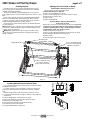
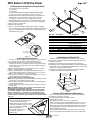
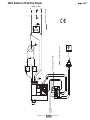
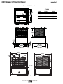
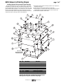
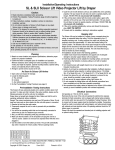
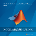
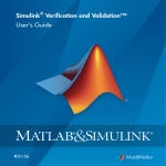
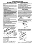
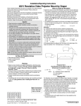
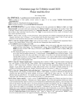
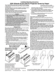
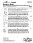
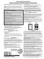
Installation/Operating Instructions
220V SLX Scissor Lift Video Projector Lift by Draper
These Installation/Operating Instructions are available in the official language of the
country where you purchase the product. Please contact your distributor to request a
copy.
Vous pourriez demander les instructions d’installation et d’opération traduises dans
la langue officielle du pays ou vous achetez le produit. Veuillez demander à votre
distributeur.
Die Gebrauchsanweisung für Installation und Konstruktion sind in der offiziellen
Sprache des Landes, indem Sie das Produkt gekauft haben, vorhanden. Fragen Sie die
jeweilige Verkaufs-Abteilung.
Caution:
① Read instructions completely before proceeding.
② Test lift prior to installation. Please Note: Packaging must be removed from lift
before testing.
③ Follow instructions carefully. Installation contrary to instructions invalidates warranty.
④ Do not obstruct operation of Scissor Lift SLX with fingers or any object. Serious
injury or damage could result.
⑤ Maximum lifting capacity is 159 kg.
⑥ Scissor Lift SLX is designed to accommodate ceiling suspended equipment.
Equipment should not be allowed to rest on optional ceiling closure during
operation (refer to section titled “Installing Projector”).
⑦ Entire bottom of unit must be unobstructed to permit proper operation. Sufficient
clearance must be allowed below projector or optional ceiling closure: 305cm for
Model SLX10, 427cm for Model SLX14, etc.
⑧ Unit must be installed level (use a carpenter’s level).
⑨ Unit operates on 220V AC.
⑩ Verify the show position when testing lift. Make required changes by referring to
adjustment instructions on page 4 of this document.
⑪ Draper does not recommend setting show position at the maintenance/service
position. For example, if you wish to have 244cm Show position, order a lift with at
least a 305cm maintenance position.
CAUTION: Before servicing unit, disconnect hardwired control and any remote control.
Note: Unit has been thoroughly inspected and tested at factory and found to be
operating properly prior to shipment.
④ Unit should be level, with weight shared more or less equally by all four
threaded mounting rods.
⑤ Bottom of unit must be unobstructed after installation. Sufficient clearance
must be allowed below projector or optional ceiling closure.
⑥ Do not use unit to support adjacent ceiling, light fixtures, etc.
⑦ Do not complete the ceiling below unit until electrical connections have
been completed and unit has been operated successfully.
⑧ We recommend that safety cables be attached to the Scissor Lift SLX for
added security (a sound installation practice with overhead equipment).
⑨ When the Scissor Lift SLX is to be installed in “other space used for
environmental air” the optional environmental air space housing must
be installed per instructions to isolate the lift from the “other space
used for environmental air.”
Electrical Connections
Unit operates on 220V AC.
Opening the electrical box exposes terminals for field connections. Unit is shipped
with internal wiring complete.Wire to connect unit to power supply should be
furnished by installer. Connections should be made in accordance with wiring
diagram, and wiring should comply with national and local electrical codes. All
operating switches should be “off” before power is connected.
Caution: Make sure electrical supply has been disconnected before
attempting to connect Scissor Lift to electricity.
Scissor Lift should be operated and checked prior to installing projector and/or
optional ceiling closure.
Low Voltage Control Switch shown below comes with 22.8 meters of cable and
should be plugged in to Control Panel on top frame of lift for control of the "Closed"
and "Show" positions. Momentary Key Switch shown below comes with 22.8
meters of cable and should be plugged in to Control Panel on top frame of lift for
control of the "Service" position.
LVC-S
SP-KSM
Service
Up & Show
Planning
① Based on screen location and projector specifications, determine proper
position for projector installation.
② Confirm that there is adequate space for installation and operation.
Minimum clearance above ceiling level varies according to Scissor Lift
model, plus height of projector, optional mounting bracket, optional ceiling
closure, and optional Environmental Air Space Housing.
③ Arrange to provide service access to the unit.
④ Maximum lifting capacity is 159 kg.
As Soon As Scissor Lift Arrives
① Open carton and inspect for damage.
② Locate the following parts:
A. The unit itself
B. Controls
C. Optional equipment: Environmental Air Space Housing, Universal
Projector Mount, closure panel or ceiling finish kit (all ship in separate
cartons).
③ Test lift prior to installation. Please Note: Packaging must be removed from
lift before testing.
Hanging Unit
Please note: If using Environmental Air Space Housing option, go to
Environmental Air Space Housing instructions on page 3.
The Scissor Lift may be installed in a variety of ways; recessed above the
ceiling, or suspended below the ceiling. The lift should be supported by four 12.7
threaded mounting rods. If ceiling recessed, the entire unit (including the projector)
should set approximately 38 mm above the finished ceiling in its “stored” position.
The threaded rods should pass through the corner mounting flanges and be
secured by nuts above and below. The unit should then be guy wired or blocked to
prevent swinging.
All installations should observe the following guidelines:
① If installing above a hard ceiling, optional Draper Access Panels are
available to allow access to the unit.
② Installer must ensure that all fasteners and supports are of adequate
strength to securely support Scissor Lift and projector.
③ Fastening methods must be suitable for mounting surface, and securely
anchored so that vibration or abusive pulling on unit will not weaken
installation.
Caution: Beware
of pinch points
®
Copyright © 2012 Draper Inc. Form 220VSLXScissorLift_Inst12
Printed in U.S.A.
UP
UP
OFF
OFF
DOWN
DOWN
Figure 1
Operation
Before operating or testing the unit, make sure the packaging has been
removed from the unit. This can be accomplished by removing the eight screws
(four per side) holding the packing frame to the lift. Once the packaging is all
removed, operate the lift in the "up" direction, so the lift's control encoder will
recognize it's "home" location. Until you do this, the Down function will not work.
You must also do this if the Scissor Lift ever loses or is disconencted from
the power.
When unit is first operated, be cautious! If unit fails to operate properly, press
“off” and recheck electrical connections before proceeding. Cycle unit down and up
several times to confirm satisfactory operation.
Caution: Do not pull on or touch safety belt when unit is in motion. If belt
locks, the cables will unspool.
Caution: Obstructing bottom pan may cause cables to unspool.
Standard Single Station Low Voltage Control (See Fig. 1) (CE Approved)—
One three-button switch with “up”, “down”, and “off” buttons. Lift starts up or
down when appropriate button is pressed, and may be stopped by pressing “off”
button. Factory set limit switches stop lift automatically when projector is in “show”
position. One momentary key switch lowers lift from “show” to “service” position.
Optional Multiple Station Control (Not CE Approved)—Optional, moves lift from
“stored” to “show” position only. Each switching station has a three-button switch
with “up”, “down”, and “off” buttons. Lift starts up or down when appropriate button
is pressed, and may be stopped by pressing “off” button. Factory set limit switches
stop lift automatically when projector is in “show” position.
Optional Key Operated Switch (Not CE Approved)—If ordered, the standard
LVC-S can be replaced with a second single station, momentary key-operated
three position (up/off/down) switch. Multiple Station Control required for this option.
Moves lift from “stored” to “show” position only.
Optional Infrared or Radio Frequency Remote Control (CE Approved)—If
ordered, a three-button transmitter is provided, with “up”, “down”, and “stop”
buttons. Unit starts up or down when appropriate button is pressed, and may be
stopped by pressing “off” button. Factory set limit switches stop unit automatically
when projector is in “show” position. Only controls "show" and "stored" positions.
Optional RS232 Control (CE Approved)—For Serial communication an R2D7
Serial Communications Interface is optionally available.
Low Voltage Trigger (CE Approved)—Input provided for Low Voltage Trigger from
projector (see diagram on page 4).
Please Note: Scissor Lift SLX must be installed in accordance with the requirements
of the Local Building Codes, the Canadian Electrical Code (CEC), CAN/CSA
C22.1 and the National Electric Code (NEC), NFPA 70, as required. An appropriate
disconnect device shall be provided as part of the building installation.
If you encounter any difficulties installing or servicing your Scissor Lift, call your dealer
or Draper, Inc. in Spiceland, Indiana, 765-987-7999, or fax 765-987-7142.
220V Scissor Lift SLX by Draper
page 2 of 7
Adjusting for Level or Center of Gravity
Installing Projector
Generally, the video projector should be suspended from the Projector
Pan according to projector manufacturer’s instructions and recommended
standard ceiling mounting hardware.
The Scissor Lift SLX has a grounded 220V AC power cord for projector
power supply. The power cord is laced down the back scissor and is “hot” at all
times.
Control cables should be laced through our Cable Management System.
Make sure to use flexible cables, and to allow enough cable at each turn
so cables do not stretch or kink. This will ensure that cords do not become
tangled and damaged during Scissor Lift SLX operation.
Unit and projection system should be operated, checked and adjusted as
necessary at this time.
NOTE: Immediately upon completion of the surrounding ceiling, units should
be operated to confirm that optional ceiling closure panel stops just short of
touching ceiling in closed position.
Warning: Keep fingers and other objects away from automatic ceiling
closure and scissor mechanisms when unit is operating. Serious injury or
damage could result.
①
②
③
④
⑤
⑥
Preferred Method—Adjusting Projector Pan
The Projector Pan can be moved forward or back.
Make sure Bottom Pan is supported.
Remove the Lifting Cable Bar (see Fig. 2).
Remove screws holding Projector Pan on Bottom Pan (see Fig. 2).
Move Bottom Pan forward or back.
Replace screws.
Replace Lifting Cable Bar.
Secondary Method—Adjusting Lifting Cable Bar
(if above does not work)
Run the unit to its "Service" position and make sure pan is level. Try and set
so that pan is not more than 19 mm out of level. However, the pan does
not have to be perfectly level, as long as the positioning is consistent
and repeatable in "Show" and "Closed" positions.
① Make sure Bottom Pan is supported.
② Remove screws holding Lifting Cable Bar to the Bottom Pan (see Fig. 2).
③ Move Lifting Cable Bar forward or back (see Fig. 2).
④ Replace screws.
⑤ Check level again. If still not level, repeat.
Attachment points
for Lifting Cables
Lifting Cable Bar
3
/8"-18 x 1" (25.4mm) hex head
cap screws for attaching Lifting
Cable Bar to Bottom Pan
¼"-20 x ¾" (19mm) hex head
cap screws for attaching
Projector Pan to Bottom Pan
Figure 2
Installing Optional Universal Projector Mount
If you ordered the unit with optional Universal Projector Mount pre-installed,
disregard these instructions.
If you did not order the mount pre-installed, you will need to install a new
Projector Pan, which includes the Universal Projector Mount's rectangular
plate.
Maximum weight capacity for the Universal Projector Mount is 11.7 kg.
① Lower unit until the Bottom Pan is resting on a tabletop or other stable and
sturdy surface.
② Remove Lifting Cable Bar from Bottom Pan (see Fig. 2).
③ Remove bolts holding Projector Pan to Bottom Pan (see Fig. 2).
④ Remove Projector Pan and set aside.
⑤ Place new Projector Pan with Universal Mount into place.
⑥ Re-attach Projector Pan to Bottom Pan.
⑦ Re-attach Lifting Cable Bar to Bottom Pan.
7"
21/16"
315/16"
12"
Figure 3
www.draperinc.com
(765) 987-7999
220V Scissor Lift SLX by Draper
page 3 of 7
Installing Projector Using Universal Projector Mount
①
②
③
④
⑤
The universal projector mount includes:
-2 x long arms
-4 x short arms
-4 x M3, 4 x M4, 4 x M5 and 4 x M6 mounting bolts (30mm in length)
-4 spacers (½" [13 mm], 5/8" [16 mm], ¾" [19 mm], 7/8" [22 mm])
Determine which size mounting bolts suit your projector, and set others
aside. They are no longer required. If your projector has only three
mounting holes, set aside one of the mounting arms (see Fig. 3).
Attach the appropriate mounting arms to the rectangular plate via center
bolt. Spread out the arms so each end is over one of the mounting holes.
Connect projector mounting arms.
Tighten the mounting bolts.
Use the ¼" (6.35 mm)-20 bolts and springs which hold the rectangular
plate to the bottom pan to adjust roll and tilt (the springs will ensure that the
projector is held still during motion). The center 5/16" (8 mm) bolt provides
Yaw adjustment (see Fig. 4).
8
Spring
¼" (6.35 mm)-20
Bolt and Washer
3
2
7
4
6
7
5
1
Item Qty
①
1
②
1
③
2
④
4
⑤
8
Detail: ¼" (6.35 mm)-20
bolts and Spring
9
Part Number
C028.546
C044.181.07SA
C002.845.07SA
C077.035.49
C013.050
⑥
8
C020.082
⑦
⑧
⑨
16
4
4
C018.027
C020.322
C018.045
Description
Frame, SLX Closure Trim
Panel, SLX Assembled Closure
Bracket, SLX Closure
Rod 3/8"-16 x 177/8" L Threaded , Zinc
Washer .375 I.D. x .875" O.D.
x .064" TK GRD 2 Zinc Flat
Screw, 10-16 X ½" 6 Lobe
Truss Head AB E-White
Nut, 3/8"-16 Hex GRD 2 NSF
Screw, 5/16"-18 x ¾" Long Grade 5 HH Zinc
Nut, 5/16"-18 Zinc Hex KEPS
Figure 5
Figure 4
Installing Optional Ceiling Closure
If your Scissor Lift SLX is equipped with optional ceiling closure, it can be used
as is, or in conjunction with a square of existing ceiling tile (see Fig. 5).
① If installing with ceiling tile, you may need to cut tile so that its overall
dimensions are the same as (or slightly less than) the closure panel. Place tile
into trim frame. Lay closure panel on top (back side) of ceiling tile, and tighten
screws to hold in place.
② Attach provided angle brackets to side of Bottom Panel of Scissor Lift SLX.
③ Attach 5/16" (8mm) threaded rods to angle bracket.
④ Run unit “up” until bottom pan stops at highest position. Mark position on 5/16"
rods even with ceiling level and cut to length (remove from pan if convenient).
⑤ Run unit “down” until bottom pan stops at “show” position.
⑥ Attach closure to lower end of 5/16" (8mm) rods by slipping into four corner slots
and secure with nuts above and below slots.
Caution: Make sure nuts are completely tightened.
⑦ Run unit “up” again to highest position. Measure distance by which panel fails to
reach required “closed” height for surrounding ceiling.
⑧ Run unit “down” then re-adjust mounting of 5/16" (8mm) rods in traveling grid to
raise panel required distance.
⑨ Test unit operation to confirm that panel will stop in closed position just before
touching ceiling.
Caution: DO NOT hang from, "ride" or pull down on the unit. This could
create a failure and cause damage and/or injury.
PLEASE NOTE: Immediately upon completion of the surrounding ceiling,
unit should be operated to confirm that optional ceiling closure panel by
Draper or by others stops 1/8" (3mm) short of touching ceiling in closed
position. If closure panel touches, the motor may continue operating after
the lift is closed. If it continues to cycle once the lift is closed, a motor failure
may occur.
For Additional Safety:
① Be sure the nuts that attach the threaded
rods to the closure panel are tight.
② Wrap a plastic wire tie around the mounting
tab and the threaded rod at all four corners
of the closure panel (see drawing).
Please Note: Do NOT use a
paper-covered or similar wire tie—
use only plastic wire ties for
maximum safety.
www.draperinc.com
Installing Optional Ceiling Trim Kit
The Scissor Lift SLX is available with a ceiling trim kit, which consists of
the lower section of the Environmental Air Space Housing and the optional
closure panel (see Fig. 6).
➀ Install Scissor Lift SLX as previously described in these instructions.
➁ Install bottom section of Environmental Air Space housing and Trim Ring in
opening. This can be accomplished by suspending with wire, or by mounting
directly to the ceiling joists (if space permits).
➂ Install projector and attach optional ceiling closure to Scissor Lift SLX,
according to the instructions included in this document.
Lower section of
Environmental Air
Space Housing
Trim Ring
Ceiling tile
(by others)
Figure 6
Scissor Lift SLX Inspection and Maintenance
Draper recommends inspecting the Scissor Lift SLX at least annually or
every 300 cycles—whichever comes first.
A recommended maintenance schedule includes:
-Cables: Check for fraying.
-Drive Chain: Check for rust, breaks, secure attachment.
-Fasteners along scissor arm assemblies: Make sure they are not loose. If
any are loose, hand tighten the nuts. (Please Note: there is no need to
tighten nut in the top scissor which slides back and forth in the side slot in
the lift. Tightening this fasteners assembly will cause the unit to lock up
and lead to damage to the unit.)
-Closure: Make sure threaded rod remains seated firmly in the closure
panel corners, and that nuts remain tight. If they are loose, tighten them.
(765) 987-7999
220V Scissor Lift SLX by Draper
page 4 of 7
Please Note:
LVT
RP/RQ
KEY
Low Voltage Trigger
(6-24 VDC)
(Polarity Independent)
Pin
123456
YGRB
Pin
123456
YGRB
Data cable connections must be made using electrically
straight 4-conductor modular cable (RJ14). If making
your own cables, this means colors do not cross over:
blue leads to blue, green to green, etc. (see diagram
below).
Pin
123456
YGRB
WALL
Controls plug into the data cable inputs on the Control Panel,
which is located on the Top Frame on the front side of the lift,
using RJ14 connectors.
For IR or RF Remote Control, use data cable with RJ14
connectors on both ends.
For serial control of "Show" position, use data cable with RJ14
connectors on both ends and an R2D7 Serial Control Interface.
Plug into the "RP/RQ" input.
RP/RQ
Function Indicator
Connecting Controls
RP/RQ Bus Ports for
remote controls such as
IR Eye, RF Receiver, LED
Wall Switch and RS232
LVC-S
SP-KSM
Red - Down
Black - Com
Black - Com
Blue - Up
Pin
123456
YGRB
Green
Black
DCU
Yellow
Pin
123456
YGRB
Green
Black
Yellow
Pin
654321
B R GY
To RS232 Port:
Yellow = Rx (Data from control system)
Green = Tx (Data to control system)
Red = Unused
Black = Gnd (Signal Ground)
Adjustments
Clear Show Position (Method 2)
① Press and hold Key in Down position to get lift to bottom limit.
② Release the Key.
③ Again, press and hold Key in the Down position.
④ Continue holding until lift starts moving up (approx. 5 sec, Key can
be released anytime after movement starts). The lift will move up for .7
seconds then stop. This indicates the Show Position is cleared.
Note that once the Show Position is cleared, the Key Switch no longer
works!
"Main" refers to commands sent via the wall switch or main channel
commands sent via IR or RF remote through the RP Bus.
CAUTION: Be sure all switches are in “off” position before adjusting limit
switch. Always be prepared to shut lift off manually when new adjustment is
being tested. Please refer to wiring diagram.
Limit switches for the Scissor Lift SLX are preset at the factory. The “Up”
limit switch is set for fully closed. The "Down" limit switch is set for the fully
down (maintenance) position for the size lift you have ordered. The limit switch
assembly is located inside the lift and behind the Lifting Cable Drum.
Set Show Position
(can only be set if it is cleared, i.e. it cannot be re-set)
① Use Main UP/DN to get lift to desired Show Position.
② Press and hold Key in the "down" position.
③ Continue holding until lift starts moving up (approx. 5 sec, Key can be
released anytime after movement starts). The lift will move up for 2
seconds, then stop for 1 second, then go down for 1 second and stop. This
action is used to measure the amount of coast that happens near the Show
Position.
④ The coast is now calculated and the Show Position set. The lift now goes
down to the Show Position, which should be where the process started.
The Up and Down limit switches shown in the drawing are for setting the "Up
and "Fully Down." These can be adjusted manually by loosening or tightening
the screws to increase or reduce the travel.
Down
Up
Limit
Switch
Clear Show Position (Method 1)
① Put the lift at the show position using the Main Down button.
② Press and hold Key in the Up position.
③ Continue holding until lift starts moving up (approx. 5 sec,
Key can be released anytime after movement starts).
The lift will move up for .75 seconds then stop. This
indicates the Show Position is cleared.
Note that once the Show Position is cleared, the Key
Switch no longer works! (See the operation above
where Show Position is not yet set.)
Down
Limit
Switch
A
Please Note: If the Scissor Lift loses or is disconnected
from the power, the "Down" function will not work until
you operate the lift in the "up" direction. This allows the
lift's control encoder to recognize it's "home" location.
www.draperinc.com
Up
(765) 987-7999
www.draperinc.com
(765) 987-7999
RD
WH
BK WH
RP/RQ Bus Ports for remote controls such as
Eye Port for IR Eye, RF Receiver, LED Wall Switch
and RS232.
RD
Key Switch
Wall Switch
WH
RD
RD
BN
WH
YL
BK
YL/GN
BN
RD
BK
WH
BK
RD
BK
Motor
Encoder
Low voltage wiring by others
Low Voltage Trigger (6-24 VDC)
DOWN Limit Switch
BN
UP Limit Switch
RD
RD
BL
BK
BL
WH
WH
WH
220V Outlet
N
Dashed wiring by electrician
BK
GN
WH
220V Scissor Lift SLX by Draper
page 5 of 7
220 Vac Supply
220V Scissor Lift SLX by Draper
page 6 of 7
Scissor Lift SLX Dimensions
Table A
973.14
mm
919.16
mm
Model
SLX10
SLX14
SLX17
SLX21
SLX24
SLX28
903.29mm
957.26mm
See
Table
A
3.175
mm
889mm
920.75mm
1008mm
1066.8mm
41.275
mm
900.1mm
941.39mm
1066.8mm
1060mm
1054mm
527mm
127mm
1231.9mm571.5mm
482.6
mm
www.draperinc.com
(765) 987-7999
Closed
Height
36cm
42cm
47cm
53cm
60cm
65cm
Extended
Height
232cm
432cm
538cm
648cm
754cm
866cm
220V Scissor Lift SLX by Draper
page 7 of 7
Installing Optional Environmental Air Space Housing
The Environmental Air Space Housing is shipped in pieces, and must be
assembled by the installer. The height of the Environmental Air Space Housing can be adjusted by moving the screws to different mounting holes in side
panels. Aluminum tape is provided to cover unused holes. It is recommended
that an access panel be installed in the ceiling to allow future access. The
optional environmental air space housing must be installed per instructions to
isolate the lift from the “other space used for environmental air.”
11
11
① Attach Environmental Air Space Housing top frame to top of Scissor Lift
SLX with bolts provided.
② Install top panel to Environmental Air Space Housing frame.
③ Attach assembly to overhead structure. Allow clearance between Environmental Air Space Housing top and structure for ease of future access.
④ Install side and end panels, and trim frame.
11
7
11
11
11
1
11
Sid
e
3
3
11
8
5
5
Front/Back
4
9
3
6
4
10
Do not use
electrical knockouts
on bottom sections
2
Item
①
②
③
④
⑤
⑥
⑦
⑧
⑨
⑩
⑪
Qty Part Number
Description
1 C028.544.02SA
Frame, SLX Plenum
1 C028.545.07SA
Frame, SLX Trim Ring
4
C044.178SA
Panel, SLX Plenum Side
4
C044.180SA
Panel, SLX Plenum End
2
C044.179SA
Panel, SLX Middle End
2
C044.177SA
Panel, SLX Plenum Middle Side
1
C095.123SA
Cover, SLX Plenum
28
C020.325
Screw, 8-32 x 3/8" Type 1 HWH
40
C018.051
Nut #8-32 Zinc Hex KEPS
12
C013.070 Washer, .188 I.D. x .5 O.D. x .07" TK Nylon Flat
24
C020.112
Screw, 8-32 x 3/8" Type F HWH
Caution: Be careful when handling Environmental Air Space
Housing Panels. The panels could have sharp edges.
www.draperinc.com
(765) 987-7999
9
3