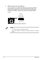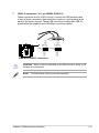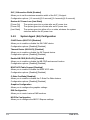
1
Industrial Motherboard
EMB-B75A
E7587
First Edition (V1)
August 2012
Copyright Notice
This document is copyrighted, 2012. All rights are reserved. The original
manufacturer reserves the right to make improvements to the products described
in this manual at any time without notice.
No part of this manual may be reproduced, copied, translated, or transmitted
in any form or by any means without the prior written permission of the original
manufacturer. Information provided in this manual is intended to be accurate and
reliable. However, the original manufacturer assumes no responsibility for its use,
or for any infringements upon the rights of third parties that may result from its use.
The material in this document is for product information only and is subject to
change without notice. While reasonable efforts have been made in the preparation
of this document to assure its accuracy, the original manufacturer assumes no
liabilities resulting from errors or omissions in this document, or from the use of the
information contained herein.
The original manufacturer reserves the right to make changes in the product
design without notice to its users.
Acknowledgments
All other products’ name or trademarks are properties of their respective owners.
•
AMI is a trademark of American Megatrends Inc.
•
Microsoft Windows® is a registered trademark of Microsoft Corp.
•
•
•
Intel®, Core™ are trademarks of Intel® Corporation.
ITE is a trademark of Integrated Technology Express, Inc.
IBM, PC/AT, PS/2, and VGA are trademarks of International Business
Machines Corporation.
The original manufacturer reserves the right to make changes in the product
design without notice to its users.
All other product names or trademarks are properties of their respective owners.
ii
Contents
Chapter 1:
Product overview
1.1
Package contents.......................................................................... 1-1
1.3
Specifications................................................................................ 1-2
1.2
Features......................................................................................... 1-1
Chapter 2:
Motherboard information
2.1
Before you proceed...................................................................... 2-1
2.3
Screw size...................................................................................... 2-4
2.2
2.4
2.5
2.6
2.7
Motherboard layout....................................................................... 2-2
2.3.1
2.3.2
2.4.1
2.4.2
Installing the CPU............................................................ 2-7
CPU heatsink and fan assembly installation.................... 2-9
System memory.......................................................................... 2-11
2.5.1
Installing a DIMM............................................................2-11
Jumpers....................................................................................... 2-12
Connectors.................................................................................. 2-14
2.7.1
Chapter 3:
Rear panel connectors................................................... 2-14
Internal connectors........................................................ 2-16
BIOS setup
BIOS setup program..................................................................... 3-1
3.1.1
BIOS menu screen........................................................... 3-2
3.1.3
Navigation keys................................................................ 3-3
3.1.2
3.1.4
3.1.5
Menu bar.......................................................................... 3-2
Menu items...................................................................... 3-3
Submenu items................................................................ 3-3
3.1.6
Configuration fields.......................................................... 3-3
3.1.8
Scroll bar.......................................................................... 3-3
3.1.7
3.2
Solder side....................................................................... 2-5
Central Processing Unit (CPU).................................................... 2-6
2.7.2
3.1
Component side............................................................... 2-4
3.1.9
Pop-up window................................................................ 3-3
General help.................................................................... 3-3
Main menu..................................................................................... 3-4
3.2.1
3.2.2
System Time [xx:xx:xx].................................................... 3-4
System Date [Day xx/xx/xxxx].......................................... 3-4
iii
Contents
3.3
Advanced menu............................................................................ 3-5
3.3.1
ACPI Setting.................................................................... 3-5
3.3.3
CPU Configuration........................................................... 3-5
3.3.5
SATA Configuration.......................................................... 3-6
3.3.7
Super IO Configuration.................................................... 3-7
3.3.2
3.3.4
3.3.6
3.4
3.5
3.6
3.7
3.3.8
Trusted Computing........................................................... 3-5
Digital IO.......................................................................... 3-6
USB Configuration........................................................... 3-7
H/W Monitor..................................................................... 3-8
Chipset........................................................................................... 3-8
3.4.1
3.4.2
PCH-IO Configuration...................................................... 3-8
System Agent (SA) Configuration.................................. 3-10
Boot menu................................................................................... 3-11
3.5.1
3.5.2
Boot Configuration..........................................................3-11
CSM parameters.............................................................3-11
Security menu............................................................................. 3-12
Administrator Password................................................................ 3-12
User Password.............................................................................. 3-13
Save & Exit menu........................................................................ 3-13
Save Changes & Reset................................................................. 3-13
Appendix
Notices........................................................................................................A-1
iv
Chapter 1
Product overview
1.1
Package contents
Check your industrial motherboard package for the following items.
1 x Industrial Motherboard
1 x Cable Kit
1 x I/O Shield
1 x DVD-ROM for manual (in PDF format) and drivers
NOTE: If any of the above items is damaged or missing, contact your
distributor or sales representative immediately.
1.2
•
•
•
•
•
•
•
•
Features
Intel Socket 1155 For 2nd Generation Core™ i7/Core™ i5/Core™ i3
Processors Up To 95W
®
Two 240-pin Dual Channel DDR3 1066/1333MHz (1600 MHz for 3rd
Generation Core™ Processors) DIMM Up To 16GB
Three Independent Display: VGA x 1 , HDMI x 3
10/100/1000Base-T x 2
SATA 6.0 Gb/s x 1, SATA 3.0 Gb/s x 2, USB3.0 x 4, USB2.0 x 10, COM x 2
PCI-Express[x16] x 1
Onboad TPM Function
EuP/ErP Compliance
Chapter 1: General information
1-1
1.3
Specifications
SYSTEM
Form factor
CPU
Mini-ITX
LGA1155 socket for Intel® 2nd Generation Core™ i7 / Core™ i5 /Core™ i3
processors
Supports Intel® 22nm CPU up to 95W
Supports Intel® Turbo Boost Technology 2.0
Memory
Chipset
I/O Chipset
Ethernet
BIOS
Wake on LAN
Watchdog Timer
H/W Status Monitor
Expansion slot
• The Intel® Turbo Boost Technology 2.0 support depends on the CPU types.
2 x DIMM (8GB per DIMM), max. 16GB, DDR3 1333 / 1066 (DDR3 1600 for
Ivy Bridge processors) MHz
Dual-channel memory architecture
Intel® B75
ITE IT8728F
Realtek® 8111F-VB-CG, 10/100/1000Base-TX
2 x RJ-45 ports
AMI Plug & Play SPI BIOS – 1 x 64MB ROM
Yes
1~255 steps by software program
Monitors CPU/system temperature
Monitors Vcore, 5V/3.3/5Vsb voltages
Monitors CPU/system fan speed
1 x PCI Express 3.0 x16 slot
Battery
Lithium battery
Power requirement
1 x 24-pin ATX connector
1 x 4-pin ATX 12V power connector
1 x CPU fan
Board size
Gross weight
1 x System fan with 4-pin wafer for Smart FAN support
6.7 in. x 6.7 in. (17.0 cm x 17.0 cm)
1.1 lb (0.5 Kg)
Operating
32oF~140oF (0oC~60oC)
temperature
Storage temperature -40oF~176oF (-40oC~80oC)
Operating humidity
0%~90% relative humidity, non-condensing
Power compliance
Compliant with Eup/ErP
Certificate
CE/FCC Class A
(continued on the next page)
1-2
EMB-B75A
DISPLAY
Chipset
Resolution
Intel® Ivy Bridge +B75
Up to 1920x1200@60Hz for CRT
Up to 1920x1080@60Hz for HDMI
Output interface
Maximum shared system memory up to 1748MB
1 x VGA port
3 x HDMI ports (1 x HDMI ports; 3 x DP to HDMI ports) on rear I/O
I/O
Storage
1 x SATA 6.0Gb/s port
Serial port
1 x RS-232/422/485 (Box header)
2 x SATA 3.0Gb/s ports
1 x RS-232 (Box header)
USB
2 x USB3.0 (Type A port ) on rear I/O
2 x USB3.0 (Box header)
2 x USB2.0 (Type A port) on rear I/O
DIO
TPM
RTC
Keyboard/Mouse
Audio
Ethernet
4 x USB2.0 (Pin header)
8-bit Digital I/O interface (4-in/4-out)
Onboard Infineon SLB9635 TT 1.2
Internal RTC
1 x PS/2 Keyboard on rear I/O
1 x PS/2 Mouse on rear I/O
Realtek ALC887-VD2-CG ,MIC-in/Line-in/ Line-out
2 x RJ-45 ports on rear I/O
Display
1 x VGA port on rear I/O
Others
1 x Front panel connector (Pin header)
3 x HDMI ports on rear I/O
NOTE: Specifications are subject to change without notice.
Chapter 1: General information
1-3
1-4
EMB-B75A
Chapter 2
Motherboard information
2.1
Before you proceed
Take note of the following precautions before you install motherboard components
or change any motherboard settings.
CAUTION!
•
Unplug the power cord from the wall socket before touching any
component.
•
Before handling components, use a grounded wrist strap or touch a safely
grounded object or a metal object, such as the power supply case, to avoid
damaging them due to static electricity.
•
Hold components by the edges to avoid touching the ICs on them.
•
Whenever you uninstall any component, place it on a grounded antistatic
pad or in the bag that came with the component.
•
Before you install or remove any component, ensure that the ATX power
supply is switched off or the power cord is detached from the power
supply. Failure to do so may cause severe damage to the motherboard,
peripherals, or components.
Main and Standby Power LEDs
The motherboard comes with one standby power LED and main power LED that
light up to indicate that the system is ON, in sleep mode, or in soft-off mode. This
is a reminder that you should shut down the system and unplug the power cable
before removing or plugging in any motherboard component. The illustration below
shows the location of the onboard LEDs.
LED2
ON
Standby Power
OFF
Powered Off
LED1
ON
Main Power
OFF
Powered Off
EMB-B75A Onboard LED
Chapter 2: Motherboard information
2-1
2.2
Motherboard layout
NOTE: Place four screws into the holes indicated by circles to secure the
motherboard to the chassis.
CAUTION! Do not overtighten the screws! Doing so can damage the
motherboard.
1
2
3
6
4 45
7
8
9
10 11
17.0cm(6.7in)
DEBUG1
USB3_23
USB89
USB1011
CLRTC1
COM2
COM1
_VSET1
COM1
Dio1
Super
I/O
HDMI2
SATA_PWR1
PS161
ATMODE
EPU
EATX_PWR2
VGA1
ASM
1442
HDMI1
Place this side
towards the rear
of the chassis
LGA1155
RTL
8111F
LAN2_USB2
Lithium Cell
CMOS Power
B75
12
F_PANEL
Intel®
CPU_FAN1
1
EATXPWR1
PS161
DDR3_B0_U1 (64bit, 240-pin module)
HDMI3
SYS_FAN1
DDR3_A0_U1 (64bit, 240-pin module)
SATA3G_1
SATA3G_2
SATA6G_1
17.0cm(6.7in)
KBMS1
LAN1_USB3
RTL
8111E
LED2
LED1
AUDIO
ALC
887
PCIEX16_1
16
2-2
13
BZ1
15
14
EMB-B75A
Connectors/Jumpers/Slots
1. ATX power connectors (24-pin EATX_PWR1, 4-pin EATX_PWR2)
2. SATA Power connector (SATA_POWER)
3. CPU and system fan connectors (4-pin CPU_FAN1, 4-pin SYS_FAN1)
4. Intel® B75 Serial ATA 6.0Gb/s connector (7-pin SATA6G_1)
5. Intel® B75 Serial ATA 3.0Gb/s connectors (7-pin SATA3G_1~2)
Page
2-16
2-23
2-17
2-19
2-19
6.
7.
8.
9.
10.
11.
12.
13.
14.
15.
16.
2-20
2-21
2-12
2-22
2-11
2-18
2-13
2-1
2-13
2-6
2-22
USB 3.0 connector (20-1 pin USB3_23)
USB 2.0 connectors (10-pin USB89, USB1011)
Clear RTC RAM (3-pin CLRTC)
Serial port connector (10-pin COM1, COM2)
DDR3 DIMM slots
System panel connector (10-1 pin F_PANEL)
COM1 Ring/+5V/+12V selection (COM1_VSET1)
Main and Standby Power LEDs (LED1, LED2)
AT Mode (ATMODE)
Intel® LGA1155 CPU socket
DIO connector (DIO1)
Chapter 2: Motherboard information
2-3
142.37
88.42
34.45
Component side
24.40
2.3.1
18.66
Screw size
7.46
8.42
2.3
171.58
168.54
162.31
161.51
152.94
142.42
141.58
125.35
124.30
111.79
104.61
103.66
92.74
89.12
81.37
74.96
55.31
52.05
48.25
46.94
41.19
35.99
30.00
20.23
13.54
8.86
12.29
4.86
0.00
2-4
160.92
127.85
131.31
170.00
150.04
78.00
51.34
30.27
9.70
0.00
36.92
103.94
107.23
107.46
149.04
82.30
79.79
51.15
27.60
29.90
30.14
36.49
36.61
43.60
0.00
3.48
4.59
10.96
36.92
EMB-B75A
6.26
14.79
142.43
Solder side
163.74
2.3.2
170.00
165.01
125.04
105.54
100.60
87.54
69.54
57.35
50.04
32.93
10.07
Chapter 2: Motherboard information
0.00
45.29
70.34
81.42
145.35
0.00
2-5
2.4
Central Processing Unit (CPU)
The motherboard comes with a surface mount LGA1155 socket designed for the
Intel® 2nd Generation Core™ i7 / Core™ i5 / Core™ i3 processors.
EMB-B75A CPU socket LGA1155
IMPORTANT: Unplug all power cables before installing the CPU.
CAUTION!
2-6
•
Upon purchase of the motherboard, ensure that the PnP cap is on
the socket and the socket contacts are not bent. Contact your retailer
immediately if the PnP cap is missing, or if you see any damage to the
PnP cap/socket contacts/motherboard components. The manufacturer will
shoulder the cost of repair only if the damage is shipment/transit-related.
•
Keep the cap after installing the motherboard. The manufacturer will
process Return Merchandise Authorization (RMA) requests only if the
motherboard comes with the cap on the LGA1155 socket.
•
The product warranty does not cover damage to the socket contacts
resulting from incorrect CPU installation/removal, or misplacement/loss/
incorrect removal of the PnP cap.
EMB-B75A
2.4.1
Installing the CPU
CAUTION! The LGA1156 CPU is incompatible with the LGA1155 socket. DO
NOT install a LGA1156 CPU on the LGA1155 socket.
1
A
B
2
Chapter 2: Motherboard information
3
2-7
4
C
A
B
5
2-8
EMB-B75A
2.4.2
CPU heatsink and fan assembly installation
CAUTION! Apply the Thermal
Interface Material to the CPU
heatsink and CPU before you
install the heatsink and fan if
necessary.
To install the CPU heatsink and fan assembly
A
1
B
B
2
A
3
Chapter 2: Motherboard information
4
2-9
To uninstall the CPU heatsink and fan assembly
1
2
A
B
B
A
2-10
EMB-B75A
2.5
System memory
2.5.1
Installing a DIMM
1
2
3
To remove a DIMM
B
A
Chapter 2: Motherboard information
2-11
2.6
1.
Jumpers
Clear RTC RAM (CLRTC)
This jumper allows you to clear the Real Time Clock (RTC) RAM in
CMOS. You can clear the CMOS memory of date, time, and system setup
parameters by erasing the CMOS RTC RAM data. The onboard button
cell battery powers the RAM data in CMOS, which include system setup
information such as system passwords.
1
2
CLRTC
Normal
(Default)
2
3
Clear RTC
EMB-B75A Clear RTC RAM
To erase the RTC RAM:
1. Turn OFF the computer and unplug the power cord.
2. Move the jumper cap from pins 1-2 (default) to pins 2-3. Keep the cap on
pins 2-3 for about 5~10 seconds, then move the cap back to pins 1-2.
3. Plug the power cord and turn ON the computer.
4. Hold down the <Del> key during the boot process and enter BIOS setup
to reenter data.
CAUTION! Except when clearing the RTC RAM, never remove the cap on
CLRTC jumper default position. Removing the cap will cause system boot
failure!
NOTES:
2-12
•
If the steps above do not help, remove the onboard battery and move the
jumper again to clear the CMOS RTC RAM data. After clearing the CMOS,
reinstall the battery.
•
You do not need to clear the RTC when the system hangs due to
overclocking. For system failure due to overclocking, use the CPU
Parameter Recall (C.P.R) feature. Shut down and reboot the system so the
BIOS can automatically reset parameter settings to default values.
EMB-B75A
2.
3.
AT Mode (ATMODE)
AT MODE
1-2
ATX MODE
2-3
COM1 Ring/+5V/+12V selection (COM1_VSET1)
+12V
+5V
RI
Com1_Vset1
+12V
+5V
RI
PIN 1
EMB-B75A COM VSET connectors
+12V
1-2
+5V
3-4
Ring
5-6
Chapter 2: Motherboard information
2-13
2.7
Connectors
2.7.1
Rear panel connectors
1
3
2
10
9
8
4 5
7
6
1.
PS/2 Mouse port (green). This port is for a PS/2 mouse.
2.
Video Graphics Adapter (VGA) port. This 15-pin port is for a VGA monitor
or other VGA-compatible devices.
3.
LAN (RJ-45) ports. These ports allow Gigabit connection to a Local Area
Network (LAN) through a network hub. Refer to the table below for the LAN
port LED indications.
LAN port LED indications
ACT/LINK LED
Status
Description
OFF
No link
ORANGE
Linked
BLINKING
Data activity
SPEED LED
Status
Description
OFF
10 Mbps
connection
ORANGE 100 Mbps
connection
GREEN
1 Gbps
connection
Activity Link
LED
Speed
LED
LAN port
4.
Line In port (light blue). This port connects the tape, CD, DVD player, or
other audio sources.
5.
Line Out port (lime). This port connects to a headphone or a speaker. In 4channel and 6-channel configurations, the function of this port becomes Front
Speaker Out.
6.
Microphone port (pink). This port connects a microphone.
NOTE: Refer to the audio configuration table on the next page for the function
of the audio ports in the 2, 4, or 6-channel configuration.
2-14
EMB-B75A
Audio 2, 4, 6-channel configuration
Port
Light Blue (Rear
panel)
2-channel
Line In
Lime (Rear panel) Line Out
Pink (Rear panel) Mic In
Lime (Front
panel)
7.
4-channel
Rear Speaker
Out
Front
Speaker Out
Mic In
6-channel
Rear Speaker
Out
Front
Speaker Out
Bass/Center
-
-
USB 3.0 ports. These two 9-pin Universal Serial Bus (USB) ports connect to
USB 3.0/2.0 devices.
NOTES:
•
DO NOT connect a keyboard / mouse to any USB 3.0 port when installing
Windows® operating system.
•
Due to USB 3.0 controller limitation, USB 3.0 devices can only be used
under Windows® OS environment and after the USB 3.0 driver installation.
•
USB 3.0 devices can only be used as data storage only.
•
We strongly recommend that you connect USB 3.0 devices to USB 3.0
ports for faster and better performance for your USB 3.0 devices.
8.
USB 2.0 ports. These two 4-pin Universal Serial Bus (USB) ports are
available for connecting USB 2.0/1.1 devices.
9.
HDMI ports. These ports are for High-Definition Multimedia Interface (HDMI)
connectors, and are HDCP compliant allowing playback of HD DVD, Blu-ray,
and other protected content.
10. PS/2 Keyboard port (purple). This port is for a PS/2 keyboard.
Chapter 2: Motherboard information
2-15
2.7.2
1.
Internal connectors
ATX power connectors (24-pin EATX_PWR1, 4-pin EATX_PWR2)
These connectors are for ATX power supply plugs. The power supply plugs
are designed to fit these connectors in only one orientation. Find the proper
orientation and push down firmly until the connectors completely fit.
EATX_PWR2
EATXPWR1
PIN 1
+12V DC
+12V DC
GND
GND
+3 Volts
+12 Volts
+12 Volts
+5V Standby
Power OK
GND
+5 Volts
GND
+5 Volts
GND
+3 Volts
+3 Volts
GND
+5 Volts
+5 Volts
+5 Volts
-5 Volts
GND
GND
GND
PSON#
GND
-12 Volts
+3 Volts
PIN 1
EMB-B75A ATX power connectors
IMPORTANT:
2-16
•
For a fully configured system, we recommend that you use a power supply
unit (PSU) that complies with ATX 12 V Specification 2.0 (or later version)
and provides a minimum power of 350 W.
•
DO NOT forget to connect the 4-pin ATX +12V power plug. Otherwise, the
system will not boot up.
•
We recommend that you use a PSU with higher power output when
configuring a system with more power-consuming devices. The system
may become unstable or may not boot up if the power is inadequate.
EMB-B75A
2.
CPU and system fan connectors (4-pin CPU_FAN1, 4-pin SYS_FAN1)
Connect the fan cables to the fan connectors on the motherboard, ensuring
that the black wire of each cable matches the ground pin of the connector.
PWM
SENSE
VCC
GND
SYS_FAN
PWM
SENSE
VCC
GND
CPU_FAN
EMB-B75A Fan connectors
CAUTION: Do not forget to connect the fan cables to the fan connectors.
Insufficient air flow inside the system may damage the motherboard
components. These are not jumpers! Do not place jumper caps on the fan
connectors!
NOTE: The CPU_FAN connector supports a CPU fan of maximum 2A (24 W)
fan power.
Chapter 2: Motherboard information
2-17
3.
System panel connector (10-1 pin F_PANEL)
This connector supports several chassis-mounted functions.
(NC)
HWRST#
GND
HD_LEDHD_LED+
PIN 1
RESET
GND
PANSWH#
PLEDPLED+
+HD_LED
PWR LED PWR BTN
F_PANEL
EMB-B75A System panel connector
•
•
•
•
2-18
System power LED (2-pin PLED)
This 2-pin connector is for the system power LED. Connect the chassis
power LED cable to this connector. The system power LED lights up when
you turn on the system power, and blinks when the system is in sleep mode.
Hard disk drive activity LED (2-pin +HDLED)
This 2-pin connector is for the HDD Activity LED. Connect the HDD Activity
LED cable to this connector. The IDE LED lights up or flashes when data is
read from or written to the HDD.
ATX power button/soft-off button (2-pin PWRBTN)
This 2-pin connector is for the system power button.
Reset button (2-pin RESET)
This 2-pin connector is for the chassis-mounted reset button for system
reboot without turning off the system power.
EMB-B75A
4.
Intel® B75 Serial ATA 3.0Gb/s connectors (7-pin SATA3G_1~2)
These connectors connect to Serial ATA 3.0 Gb/s hard disk drives and optical
drives via Serial ATA 3.0 Gb/s signal cables.
SATA3G_1
SATA3G_2
GND
RSATA_RXP1
RSATA_RXN1
GND
RSATA_TXN1
RSATA_TXP1
GND
GND
RSATA_RXP2
RSATA_RXN2
GND
RSATA_TXN2
RSATA_TXP2
GND
EMB-B75A SATA 3.0Gb/s connectors
NOTES:
5.
•
You must install Windows® XP Service Pack 3 or later version before using
Serial ATA hard disk drives.
•
When using hot-plug and NCQ, set the SATA Mode Selection item in the
BIOS to [AHCI]. See section 3.3.5 SATA Configuration for details.
Intel® B75 Serial ATA 6.0Gb/s connector (7-pin SATA6G_1)
ThIS connector connects to Serial ATA 6.0 Gb/s hard disk drives via Serial
ATA 6.0 Gb/s signal cables.
SATA6G_1
GND
RSATA_RXP1
RSATA_RXN1
GND
RSATA_TXN1
RSATA_TXP1
GND
EMB-B75A SATA 6.0Gb/s connector
NOTES:
•
You must install Windows® XP Service Pack 3 or later version before using
Serial ATA hard disk drives.
•
When using hot-plug and NCQ, set the SATA Mode Selection item in the
BIOS to [AHCI]. See section 3.3.5 SATA Configuration for details.
Chapter 2: Motherboard information
2-19
6.
USB 3.0 connector (20-1 pin USB3_23)
This connector is for the additional USB 3.0 ports. Connect the USB 3.0
bracket cable to this connector, then install the USB 3.0 bracket to the
rear side of the chassis. If your chassis support customized front panel
installation, with USB 3.0 header, you can have a front panel USB 3.0
solution.
+5V
USB3_RX_DN3
USB3_RX_DP3
GND
USB3_TX_DN3
USB3_TX_DP3
GND
S_USB_PN2_R
S_USB_PP2_R
GND
USB3_23
+5V
USB3_RX_DN2
USB3_RX_DP2
GND
S_U3TXDN4
S_U3TXDP4
GND
S_U3RXDP4
S_U3RXDN4
PIN 1
EMB-B75A USB3.0 Front panel connector
NOTES:
2-20
•
The USB 3.0 module is purchased separately.
•
Due to Intel® limitations, the USB3_34 only supports Windows® 7 operating
system.
EMB-B75A
USB 2.0 connectors (10-1 pin USB89, USB1011)
GND
GND
S_USB_PP11_R
S_USB_PN11_R
+5V
These connectors are for USB 2.0 ports. Connect the USB module cable
to any of these connectors, then install the module to a slot opening at the
back of the system chassis. These USB connectors comply with USB 2.0
specification that supports up to 480 Mbps connection speed.
GND
GND
S_USB_PP9_R
S_USB_PN9_R
+5V
PIN 1
USB1011
+5V
S_USB_PN8_R
S_USB_PP8_R
GND
GND
USB89
PIN 1
+5V
S_USB_PN10_R
S_USB_PP10_R
GND
GND
7.
EMB-B75A USB2.0 connectors
CAUTION! Never connect a 1394 cable to the USB connectors. Doing so will
damage the motherboard!
NOTE: The USB module cable is purchased separately.
Chapter 2: Motherboard information
2-21
Serial port connectors (10-1 pin COM1, COM2)
These connectors are for serial (COM) ports. Connect the serial port module
cable to this connector, then install the module to a slot opening at the back
of the system chassis.
DCD
TXD
GND
RTS
RI
PIN 1
RXD
DTR
DSR
CTS
COM1
RXD
DTR
DSR
CTS
COM2
PIN 1
DCD
TXD
GND
RTS
RI
8.
EMB-B75A Serial port connectors
NOTE: The COM module is purchased separately.
DIO connector
DIO_I#2 (GP47)
DIO_I#4 (GP16)
DIO_O#2 (GP34)
DIO_O#4 (GP12)
GND
9.
PIN 1
DIO_I#1 (GP22)
DIO_I#3 (GP64)
DIO_O#1 (GP36)
DIO_O#3 (GP35)
+V5S
DIO1
EMB-B75A DIO connector
2-22
EMB-B75A
10. SATA power connector (SATA_POWER)
EMB-B75A SATA_POWER connector
Chapter 2: Motherboard information
2-23
2-24
EMB-B75A
Chapter 3
BIOS setup
3.1
BIOS setup program
Use the BIOS Setup program to update the BIOS or configure its parameters. The
BIOS screens include navigation keys and brief online help to guide you in using
the BIOS Setup program.
Entering BIOS Setup at startup
To enter BIOS Setup at startup:
•
Press <Delete> during the Power-On Self Test (POST). If you do not press
<Delete>, POST continues with its routines.
Entering BIOS Setup after POST
To enter BIOS Setup after POST:
•
Press <Ctrl>+<Alt>+<Del> simultaneously.
•
Press the power button to turn the system off then back on. Do this option only
if you failed to enter BIOS Setup using the first two options.
•
Press the reset button on the system chassis.
NOTE: Using the power button, reset button, or the <Ctrl>+<Alt>+<Del> keys
to force reset from a running operating system can cause damage to your data
or system. We recommend to always shut down the system properly from the
operating system.
IMPORTANT:
•
The default BIOS settings for this motherboard apply for most conditions
to ensure optimum performance. If the system becomes unstable after
changing any BIOS settings, load the default settings to ensure system
compatibility and stability. Select any of the load default settings under the
Save & Exit Menu. See section 3.8 Save & Exit Menu.
•
The BIOS setup screens shown in this section are for reference purposes
only, and may not exactly match what you see on your screen.
Chapter 3: BIOS setup
3-1
3.1.1
BIOS menu screen
Menu items
Main
Menu bar
Configuration fields
General help
Aptio Setup Utility - Copyright (C) 2011 American Megatrends, Inc.
Advanced
Chipset
Boot
Security
Save & Exit
BIOS Information
EMB-B75A R0.4(EM75A04) (05/21/2012
BIOS Vendor
Core Version
Compliancy
American Megatrends
4.6.5.3
UEFI 2.3; PI 1.2
Set the Date. Use Tab
to switch between
Date elements.
System Date [Mon 12/14/2009]
System Time [23:35:31]
Access Level
Administrator
:
:
Enter:
+-
F1:
F2:
F4:
ESC
:
Select Screen
Select Item
Select
Change Opt.
General Help
Previous Values
Save and Exit
Exit
Version 2.14.1219. Copyright (C) 2011, American Megatrends, Inc.
Navigation keys
3.1.2
Menu bar
The menu bar on top of the screen has the following main items:
Main
Advanced
Chipset
Boot
For changing the basic system configuration.
For changing the advanced system settings.
For changing the chipset configuration.
For changing the system boot configuration.
Security
For selecting the exit options and loading default settings.
Save &
Exit
For selecting the exit options and loading default settings.
To select an item on the menu bar, press the right or left arrow key on the keyboard
until the desired item is highlighted.
3-2
EMB-B75A
3.1.3
Navigation keys
At the bottom right corner of a menu screen are the navigation keys for that
particular menu. Use the navigation keys to select items in the menu and change
the settings.
NOTE: Some of the navigation keys differ from one screen to another.
3.1.4
Menu items
The highlighted item on the menu bar displays the specific items for that menu. For
example, selecting Main shows the Main menu items.
The other items on the menu bar have their respective menu items.
3.1.5
Submenu items
A solid triangle before each item on any menu screen means that the item has a
submenu. To display the submenu, select the item and press <Enter>.
3.1.6
Configuration fields
These fields show the values for the menu items. If an item is user- configurable,
you can change the value of the field opposite the item. You cannot select an
item that is not user-configurable.A configurable field is enclosed in brackets, and
is highlighted when selected. To change the value of a field, select it then press
<Enter> to display a list of options.
3.1.7
Pop-up window
Select a menu item then press <Enter> to display a pop-up window with the
configuration options for that item.
3.1.8
Scroll bar
A scroll bar appears on the right side of a menu screen when there are items that
do not fit on the screen. Press the <Up> / <Down> arrow keys or <Page Up>
/<Page Down> keys to display the other items on the screen.
3.1.9
General help
At the top right corner of the menu screen is a brief description of the selected
item.
Chapter 3: BIOS setup
3-3
3.2
Main menu
When you enter the BIOS Setup program, the Main menu screen appears, giving
you an overview of the basic system information.
Refer to section 3.1.1 BIOS menu screen for information on the menu screen
items and how to navigate through them.
Main
Aptio Setup Utility - Copyright (C) 2011 American Megatrends, Inc.
Advanced
Chipset
Boot
Security
Save & Exit
BIOS Information
RO.9 (EM75AT09) (08/15/2012)
BIOS Vendor
Core Version
Compliancy
American Megatrends
4.6.5.3
UEFI 2.3; PI 1.2
System Date [Thu 01/22/2009]
System Time [23:35:31]
Access Level
Administrator
Set the Date. Use Tab
to switch between
Date elements.
: Select Screen
: Select Item
Enter: Select
+-: Change Opt.
F1: General Help
F2: Previous Values
F3: Optimized Defaults
F4: Save and Exit
ESC: Exit
Version 2.14.1219. Copyright (C) 2011, American Megatrends, Inc.
3.2.1
System Time [xx:xx:xx]
Allows you to set the system time.
3.2.2
System Date [Day xx/xx/xxxx]
Allows you to set the system date.
3-4
EMB-B75A
3.3
Advanced menu
The Advanced menu items allow you to change the settings for the CPU and
other system devices.
Be cautious when changing the settings of the Advanced menu items. Incorrect
field values can cause the system to malfunction.
Main
Aptio Setup Utility - Copyright (C) 2011 American Megatrends, Inc.
Advanced
Chipset
Boot
Security
Save & Exit
ACPI Setting
Trusted Computing
CPU Configuration
Digital IO
SATA Configuration
USB Configuration
Super IO Configuration
H/W Monitor
3.3.1
System ACPI
Parameters.
ACPI Setting
The items in this menu allows you to configure the system ACPI parameters.
ACPI Sleep State [S3 only (Suspend to...]
Allows you to select the ACPI sleep state that the system will enter when the
SUSPEND button is pressed. Configuration options: [Suspend Disabled] [S1
only(CPU Stop Clock] [S3 only(Suspend to RAM)]
3.3.2
Trusted Computing
The items in this menu allows you to configure the Trusted Computing settngs.
Security Device Support [Disabled]
Allows you to enable or disable BIOS support for security device. O.S. will not
show Security Device. TCG EFI protocol and INT1A interface will not be available.
Configuration options: [Disabled] [Enabled]
3.3.3
CPU Configuration
The items in this menu show the CPU-related information that the BIOS
automatically detects.
Hyper-threading [Enabled]
Enabled for Windows XP and Linux (OS optimized for Hyper-Threading
Technology) and Disabled for other OS (OS not optimized for Hyper-Threading
Technology). When Disabled, only one thread per enabled core is enabled.
Chapter 3: BIOS setup
3-5
Intel(R) Virtualization Tech [Enabled]
Enables or disables Intel® Virtualization Technology. Virtualization enhanced by
Intel® Virtualization Technology allows a platform to run multiple operating systems
and applications in independent partitions. With virtualization, one computer
system can function as multiple virtual systems.
Configuration options: [Enabled] [Disabled]
3.3.4
Digital IO
The items in this menu allow you to set the GPIO values.
DIO_P#1~P#8 [Input]
Allows you set GPIO as input or output. Configuration options: [Input] [Output]
DIO_P#1~P#8 Direction [Low]
This item appears when DIO_P#1~P#5 is set as [Output].
Configuration options: [High] [Low]
3.3.5
SATA Configuration
While entering Setup, the BIOS automatically detects the presence of SATA
devices. The SATA Port items show Empty if no SATA device is installed to the
corresponding SATA port.
SATA Controller(s) [Enabled]
Allows you to enable or disable SATA devices.
Configuration options: [Enabled] [Disabled]
The following item appear when you set the SATA Controller(s) item to
[Enabled].
SATA Mode Selection [IDE]
Allows you to set the SATA configuration.
[IDE]
[AHCI]
Set to [IDE] when you want to use the Serial ATA hard disk drives as
Parallel ATA physical storage devices.
Set to [AHCI] when you want the SATA hard disk drives to use the
AHCI (Advanced Host Controller Interface). The AHCI allows the
onboard storage driver to enable advanced Serial ATA features that
increases storage performance on random workloads by allowing the
drive to internally optimize the order of commands.
IDE Legacy/Native Mode Selection [Native]
Allows you to select the SATA mode selection.
Configuration options: [Native] [Legacy]
3-6
EMB-B75A
3.3.6 USB Configuration
The items in this menu allow you to change the USB-related features.
The USB Devices item shows the auto-detected values. If no USB device is
detected, the item shows None.
Legacy USB Support [Enabled]
[Enabled]
[Disabled]
[Auto]
Enables the support for USB devices on legacy operating systems
(OS).
The USB devices can be used only for the BIOS setup program.
Allows the system to detect the presence of USB devices at
startup. If detected, the USB controller legacy mode is enabled. If
no USB device is detected, the legacy USB support is disabled.
USB3.0 Support [Enabled]
[Enabled]
[Disabled]
3.3.7
Enables the USB 3.0 (XHCI) Controller support.
Disables the function.
Super IO Configuration
The items in this menu allow you to configure the system super IO chip settings.
Serial Port 1/Port 2 Configuration
Allow you to configure the Serial Port 1/Port 2 settings.
Serial Port [Enabled]
Enables or disables the Serial COM port.
Configuration options: [Enabled] [Disabled]
Change Settings [Auto]
Allows you to select an optimal setting for the Super IO device.
Configuration options: [Auto] [IO=3F8h; IRQ=4] [IO=3F8h; IRQ=3,4,5,6,7,8,9,10,11,12]
[IO=2F8h; IRQ=3,4,5,6,7,8,9,10,11,12] [IO=3E8h; IRQ=3,4,5,6,7,8,9,10,11,12]
[IO=2E8h; IRQ=3,4,5,6,7,8,9,10,11,12]
Device Mode [RS-232]
Allows you to change the Serial Port mode.
Configuration options: [RS-232] [RS-422] [RS-485]
EUP Function [Enabled]
Allows you to enable or disable the EUP function.
Configuration options: [Disabled] [Enabled]
Chapter 3: BIOS setup
3-7
3.3.8
H/W Monitor
The items in this menu allows you to monitor the hardware status.
CPU Fan/SYS Fan Control [Enabled]
Allows you to enable or disable CPU Fan/System Fan Control.
[Enabled]
Fan will run based on the user-defined settings.
[Disabled]
Fan will always run at full speed.
The following two items appear when you set the CPU Fan/SYS Fan Control
item to [Enabled].
Fan Control Mode [Manual Mode]
Allows you to set the Fan Control configuration.
[Manual Mode]
[Automatic Mode]
Fan speed depends on PWM Duty.
Fan speed depends on the CPU temperature.
PWM Duty
Allows you to enter the value for PWM Duty.
Configuration options: [0 ~ 255]
3.4
Chipset
The Chipset menu allows you to change the advanced chipset settings. Select an
item then press <Enter> to display the sub-menu.
3.4.1
PCH-IO Configuration
PCIE Express Configuration
Allows you to configure the PCI Express settings.
USB Configuration
Allows you to configure the USB settings.
PCH Azalia Configuration
Allows you to configure the PCH Azalia settings.
3-8
EMB-B75A
BIOS Security Configuration
Allows you to configure the BIOS Security settings.
Power Mode [Enabled]
Allows you to select the power supply type.
Configuration options: [ATX Type] [AT Type]
Resume on PCIE Wake [Enabled]
Allows you to enable or disable PCIE devices to generate a wake event.
Configuration options: [Enabled] [Disabled]
Resume on PCI PME [Enabled]
Allows you to enable or disable the PCI PME wake function.
Configuration options: [Enabled] [Disabled]
Resume on Ring [Enabled]
Allows you to enable or disable Ring to generate a wake event.
Configuration options: [Enabled] [Disabled]
DeepSx Power Policies [Disabled]
Allows you to enable or disable the DeepSx mode.
Configuration options: [Enabled] [Disabled]
Display Logic [Enabled]
Allows you to enable or disable the PCH Display logic.
Configuration options: [Enabled] [Disabled]
CLKRUN# Logic [Enabled]
Allows you to enable or disable the CLKRUN# logic to stop the PCI clocks.
Configuration options: [Enabled] [Disabled]
SB CRID [Enabled]
Allows you to enable or disable the SB Compatible Revision ID.
Configuration options: [Enabled] [Disabled]
High Precision Timer [Enabled]
Allows you to enable or disable the Precision Event Timer.
Configuration options: [Enabled] [Disabled]
Chapter 3: BIOS setup
3-9
SLP_S4 Assertion Width [Enabled]
Allows you to set the minimum assertion width of the SLP_S4 signal.
Configuration options: [1-2 seconds] [2-3 seconds] [3-4 seconds] [4-5 seconds]
Restore AC Power Loss [Last State]
[Power On]
[Power Off]
[Last State]
3.4.2
The system goes into on state after an AC power loss.
The system goes into off state after an AC power loss.
The system goes into either off or on state, whatever the system
state was before the AC power loss.
System Agent (SA) Configuration
CHAP Device (B0:D7:F0 [Disabled]
Allows you to enable or disable the SA CHAP device.
Configuration options: [Enabled] [Disabled]
Thermal Device (B0:D4:F0) [Disabled]
Allows you to enable or disable the SA Thermal device.
Configuration options: [Enabled] [Disabled]
Enable NB CRID (B0:D4:F0) [Disabled]
Allows you to enable or disable the NB CRID workaround function.
Configuration options: [Enabled] [Disabled]
BDAT ACPI Table Support [Disabled]
Allows you to enable or disable the BDAT ACPI table.
Configuration options: [Enabled] [Disabled]
C-State Pre-Wake [Disabled]
Allows you to enable or disable the C-State Pre-Wake feature.
Configuration options: [Enabled] [Disabled]
Graphics Configuration
Allows you to configure the graphics settings.
DMI Configuration
Allows you to control various DMI functions.
NB PCIe Configuration
Allows you to configure the NB PCI Express settings.
3-10
EMB-B75A
Memory Configuration
Allows you to configure the memory settings.
Memory Thermal Configuration
Allows you to configure the Memory Thermal settings.
GT-Power Management Control
Allows you to configure the Power Management Control settings.
3.5
Boot menu
The Boot menu items allow you to change the system boot options.
3.5.1
Boot Configuration
Quiet Boot [Enabled]
Enables or disables the Quiet Boot option.
Configuration options: [Enabled] [Disabled]
3.5.2
CSM parameters
The items in this menu allows you to configure the CSM settings.
Launch CSM [Always]
Allows you to control the CSM launch. Configuration options: [Always] [Never]
Boot option filter [UEFI and Legacy]
This option controls what devices the system can boot to.
Configuration options: [UEFI and Legacy] [Legacy only] [UEFI only]
Launch PXE OpROM policy [Do not launch]
Controls the launch of UEFI and Legacy PXE OpROM.
Configuration options: [Do not launch] [UEFI only] [Legacy only]
Launch Storage OpROM policy [Legacy only]
Controls the launch of UEFI and Legacy Storage OpROM.
Configuration options: [Do not launch] [UEFI only] [Legacy only]
Chapter 3: BIOS setup
3-11
Launch Video OpROM policy [Legacy only]
Controls the launch of UEFI and Legacy Video OpROM.
Configuration options: [Do not launch] [UEFI only] [Legacy only]
Other PCI device ROM priority [Legacy OpROM]
These items specify the boot device priority sequence from the available devices.
Configuration options: [Legacy OpROM] [UEFI OpROM]
3.6
Security menu
The Security menu items allow you to change the system security settings.
Administrator Password
If you have set an administrator password, we recommend that you enter the
administrator password for accessing the system. Otherwise, you might be able to
see or change only selected fields in the BIOS setup program.
To set an administrator password:
1.
Select the Administrator Password item and press <Enter>.
2.
From the Create New Password box, key in a password, then press
<Enter>.
3.
Confirm the password when prompted.
To change an administrator password:
1.
Select the Administrator Password item and press <Enter>.
2.
From the Enter Current Password box, key in the current password, then
press <Enter>.
3.
From the Create New Password box, key in a new password, then press
<Enter>.
4.
Confirm the password when prompted.
To clear the administrator password, follow the same steps as in changing an
administrator password, but press <Enter> when prompted to create/confirm the
password. After you clear the password, the Administrator Password item on top of
the screen shows Not Installed.
3-12
EMB-B75A
User Password
If you have set a user password, you must enter the user password for accessing
the system. The User Password item on top of the screen shows the default Not
Installed. After you set a password, this item shows Installed.
To set a user password:
1.
Select the User Password item and press <Enter>.
2.
From the Create New Password box, key in a password, then press
<Enter>.
3.
Confirm the password when prompted.
To change a user password:
1.
Select the User Password item and press <Enter>.
2.
From the Enter Current Password box, key in the current password, then
press <Enter>.
3.
From the Create New Password box, key in a new password, then press
<Enter>.
4.
Confirm the password when prompted.
To clear the user password, follow the same steps as in changing a user password,
but press <Enter> when prompted to create/confirm the password. After you clear
the password, the User Password item on top of the screen shows Not Installed.
3.7
Save & Exit menu
The Save & Exit menu items allow you to load the optimal default values for the
BIOS items, and save or discard your changes to the BIOS items.
Save Changes & Reset
This option allows you to save the changes and exit the Setup program.
Discard Changes & Exit
This option allows you to exit the Setup program without saving your changes.
When you select this option or if you press <Esc>, a confirmation window appears.
Select Yes to discard changes and exit.
Chapter 3: BIOS setup
3-13
Restore Defaults
This option allows you to load the default values for each of the parameters on the
Setup menus. When you select this option or if you press <F3>, a confirmation
window appears. Select Yes to load the default values.
Save as User Defaults
This option allows you to save the current changes as the user’s default values.
Restore User Defaults
This option allows you to load the user’s default values.
3-14
EMB-B75A
Appendix
Notices
Federal Communications Commission Statement
This device complies with Part 15 of the FCC Rules. Operation is subject to the
following two conditions:
• This device may not cause harmful interference.
•
This device must accept any interference received including interference that
may cause undesired operation.
This equipment has been tested and found to comply with the limits for a
Class B digital device, pursuant to Part 15 of the FCC Rules. These limits are
designed to provide reasonable protection against harmful interference in a
residential installation. This equipment generates, uses and can radiate radio
frequency energy and, if not installed and used in accordance with manufacturer’s
instructions, may cause harmful interference to radio communications. However,
there is no guarantee that interference will not occur in a particular installation. If
this equipment does cause harmful interference to radio or television reception,
which can be determined by turning the equipment off and on, the user is
encouraged to try to correct the interference by one or more of the following
measures:
• Reorient or relocate the receiving antenna.
•
Increase the separation between the equipment and receiver.
•
Consult the dealer or an experienced radio/TV technician for help.
•
Connect the equipment to an outlet on a circuit different from that to which the
receiver is connected.
WARNING! The use of shielded cables for connection of the monitor to the
graphics card is required to assure compliance with FCC regulations. Changes
or modifications to this unit not expressly approved by the party responsible for
compliance could void the user’s authority to operate this equipment.
EMB-B75A
A-1
A-2
EMB-B75A