1
WTI Part No. 13027
Rev. F
CMS-16 / CMS-8
Console Management Switches
Firmware Version 4.0 and Higher
User's Guide
Warnings and Cautions:
No Serviceable Parts Inside;
Authorized Service Personnel Only
Do not attempt to repair or service this device yourself. Internal
components must be serviced by authorized personnel only.
• Shock Hazard - Do Not Enter
Nameplate Power Warning
This device should only be operated with the type of power
source indicated on the instrument nameplate. If you are not
sure of the type of power service available, consult your local
power company.
• Connect unit only to a properly measured supply. Use
only three wire cord which is provided with the unit.
Rack Mount Installation
When installing this device in an instrument rack, the following
factors must be accounted for:
1. Enclosed Racks: Enclosed racks must provide adequate
ventilation. Make certain that the rack is not overly
crowded and note that each unit in the rack generates its
own heat. An enclosed rack should have louvered sides
and a fan to circulate cooling air. The maximum
temperature for the equipment in this environment is 45° C.
When mounting the unit in an enclosed rack with a
ventilation fan at the top of the rack, note that excessive
heat generated by devices at the bottom of the rack can be
drawn upward and into the ventilation slots of units located
at the top. Make certain to provide adequate ventilation for
equipment installed at the bottom of the rack.
2. Open Racks: Make certain that the rack frame does not
block the ventilation slots on the instrument cover. If the
device is installed on sliders, check the unit when seated
all the way into the rack to make certain that ventilation
slots are not blocked.
i
CMS-16 / CMS-8 User's Guide
Ventilation
Slots in the instrument cover are provided to allow ventilation
for heat dissipation. To ensure safe, reliable operation, these
openings must not be covered or blocked.
Disconnect Power
If any of the following events are noted, immediately disconnect
the unit from the outlet and contact qualified service personnel:
1. If the power cord becomes frayed or damaged.
2. If liquid has been spilled into the device or if the device
has been exposed to rain or water.
ii
Table of Contents
1.
2.
Introduction . . . . . . . . . . . . . . . . . . . . . . . . . . . . . . . . . . . . . . . . . . . . 1-1
Unit Description . . . . . . . . . . . . . . . . . . . . . . . . . . . . . . . . . . . . . . . . 2-1
3.
4.
Getting Started . . . . . . . . . . . . . . . . . . . . . . . . . . . . . . . . . . . . . . . . . 3-1
Hardware Installation . . . . . . . . . . . . . . . . . . . . . . . . . . . . . . . . . . . 4-1
2.1.
2.2.
4.1.
4.2.
4.3.
4.4.
4.5.
4.6.
5.
Connecting Power to the CMS Unit . . . . . . . . . . . . . . . . . . . . . . 4-1
4.1.1. AC Powered Units. . . . . . . . . . . . . . . . . . . . . . . . . . . . . . 4-1
4.1.2. DC Powered Units. . . . . . . . . . . . . . . . . . . . . . . . . . . . . . 4-2
Configure Option Switches . . . . . . . . . . . . . . . . . . . . . . . . . . . . . 4-2
4.2.1. Default Baud Rate (Sw1, Sw2, Sw3) . . . . . . . . . . . . . . 4-3
4.2.2. Default Handshake (Sw4, Sw5) . . . . . . . . . . . . . . . . . . 4-3
4.2.3. Default Response Message Format (Sw6) . . . . . . . . . 4-4
4.2.4. Default Command Echo (Sw7) . . . . . . . . . . . . . . . . . . . 4-4
Initialize Unit to Default Settings . . . . . . . . . . . . . . . . . . . . . . . 4-4
Connecting the Network Cable . . . . . . . . . . . . . . . . . . . . . . . . . . 4-5
Connecting Devices to the CMS . . . . . . . . . . . . . . . . . . . . . . . . . 4-5
Application Example. . . . . . . . . . . . . . . . . . . . . . . . . . . . . . . . . . . 4-6
Configuration . . . . . . . . . . . . . . . . . . . . . . . . . . . . . . . . . . . . . . . . . . 5-1
5.1.
5.2.
5.3.
5.4.
5.5.
5.6.
5.7.
6.
Front Panel . . . . . . . . . . . . . . . . . . . . . . . . . . . . . . . . . . . . . . . . . . . 2-1
Back Panel . . . . . . . . . . . . . . . . . . . . . . . . . . . . . . . . . . . . . . . . . . . 2-2
Access to the CMS Command Mode . . . . . . . . . . . . . . . . . . . . . 5-1
System SetUp Ports . . . . . . . . . . . . . . . . . . . . . . . . . . . . . . . . . . . . 5-2
Password Functions . . . . . . . . . . . . . . . . . . . . . . . . . . . . . . . . . . . . 5-3
5.3.1. The Supervisor Password. . . . . . . . . . . . . . . . . . . . . . . . 5-3
5.3.2. The Port Passwords . . . . . . . . . . . . . . . . . . . . . . . . . . . . . 5-4
Defining the Site ID and Supervisor Password . . . . . . . . . . . . 5-5
Port Configuration . . . . . . . . . . . . . . . . . . . . . . . . . . . . . . . . . . . . . 5-6
5.5.1. Configuration Conventions . . . . . . . . . . . . . . . . . . . . . . 5-6
5.5.2. Port Modes . . . . . . . . . . . . . . . . . . . . . . . . . . . . . . . . . . . . 5-7
5.5.3. RS232 Port Configuration Menus . . . . . . . . . . . . . . . . 5-8
5.5.4. Network Port Configuration Menu . . . . . . . . . . . . . . 5-15
5.5.5. Implementing IP Security . . . . . . . . . . . . . . . . . . . . . . 5-19
Copying Parameters to Several RS-232 Ports . . . . . . . . . . . . 5-21
Save User Selected Parameters . . . . . . . . . . . . . . . . . . . . . . . . . 5-23
The Status Screens . . . . . . . . . . . . . . . . . . . . . . . . . . . . . . . . . . . . . . 6-1
6.1.
6.2.
6.3.
6.4.
The
The
The
The
Port Status Screen (/S) . . . . . . . . . . . . . . . . . . . . . . . . . . . . . 6-1
Port Diagnostics Screen (/SD). . . . . . . . . . . . . . . . . . . . . . . 6-3
Network Status Screen (/SN) . . . . . . . . . . . . . . . . . . . . . . . 6-5
Port Parameters Screens (/W) . . . . . . . . . . . . . . . . . . . . . . 6-7
iii
CMS-16 / CMS-8 User's Guide
7.
Operation . . . . . . . . . . . . . . . . . . . . . . . . . . . . . . . . . . . . . . . . . . . . . . 7-1
7.1.
7.2.
7.3.
7.4.
8.
Any-to-Any Mode . . . . . . . . . . . . . . . . . . . . . . . . . . . . . . . . . . . . . 7-1
7.1.1. Port Connection and Disconnection . . . . . . . . . . . . . . . 7-1
7.1.2. Defining Hunt Groups . . . . . . . . . . . . . . . . . . . . . . . . . . 7-6
Passive Mode . . . . . . . . . . . . . . . . . . . . . . . . . . . . . . . . . . . . . . . . . 7-7
Buffer Mode . . . . . . . . . . . . . . . . . . . . . . . . . . . . . . . . . . . . . . . . . . 7-8
7.3.1. Reading Data from Buffer Mode Ports . . . . . . . . . . . . 7-8
7.3.2. Port Buffers . . . . . . . . . . . . . . . . . . . . . . . . . . . . . . . . . . . 7-9
Modem Mode . . . . . . . . . . . . . . . . . . . . . . . . . . . . . . . . . . . . . . . . 7-10
Telnet Capabilities . . . . . . . . . . . . . . . . . . . . . . . . . . . . . . . . . . . . . . 8-1
8.1.
8.2.
8.3.
8.4.
Network Port Numbers . . . . . . . . . . . . . . . . . . . . . . . . . . . . . . . . . 8-1
The Direct Connect Feature . . . . . . . . . . . . . . . . . . . . . . . . . . . . 8-2
Inbound Telnet Connections . . . . . . . . . . . . . . . . . . . . . . . . . . . . 8-6
Outbound Telnet Connections . . . . . . . . . . . . . . . . . . . . . . . . . . . 8-7
9. Saving and Restoring Configuration Parameters . . . . . . . . . . 9-1
10. Upgrading CMS Firmware . . . . . . . . . . . . . . . . . . . . . . . . . . . . . 10-1
11. Command Reference Guide . . . . . . . . . . . . . . . . . . . . . . . . . . . . . 11-1
11.1.
11.2.
11.3.
11.4.
Command
Command
Command
Command
Conventions . . . . . . . . . . . . . . . . . . . . . . . . . . . . . . . . 11-1
Response . . . . . . . . . . . . . . . . . . . . . . . . . . . . . . . . . . 11-2
Summary . . . . . . . . . . . . . . . . . . . . . . . . . . . . . . . . . . 11-3
Set . . . . . . . . . . . . . . . . . . . . . . . . . . . . . . . . . . . . . . . . 11-4
Appendices:
A. RS232 Port Interface . . . . . . . . . . . . . . . . . . . . . . . . . . . . . . . . . Apx-1
B. Specifications . . . . . . . . . . . . . . . . . . . . . . . . . . . . . . . . . . . . . . . . Apx-2
C. Customer Service . . . . . . . . . . . . . . . . . . . . . . . . . . . . . . . . . . . . Apx-3
List of Figures
2.1.
2.2.
2.3.
3.1.
3.2.
4.1.
4.2.
5.1.
5.2.
5.3.
5.4.
5.5.
6.1.
6.2.
6.3.
6.4.
6.5.
A.1.
iv
Instrument Front Panel (Model CMS-16 Shown) . . . . . . . . . . . . . . 2-1
Instrument Back Panel (Model CMS-16) . . . . . . . . . . . . . . . . . . . . . 2-2
Instrument Back Panel (Model CMS-8) . . . . . . . . . . . . . . . . . . . . . . 2-2
The Port Status Screen (Model CMS-16, Defaults Shown) . . . . . . 3-2
The Supervisor Level Help Screen . . . . . . . . . . . . . . . . . . . . . . . . . . . 3-3
Terminal Block Assembly (DC Units Only) . . . . . . . . . . . . . . . . . . . 4-2
CMS Application Example (Model CMS-16 Shown) . . . . . . . . . . . 4-6
Port Configuration Menu (Port 2 Shown) . . . . . . . . . . . . . . . . . . . . . 5-8
Port Parameters Menu (Modem Mode) . . . . . . . . . . . . . . . . . . . . . . 5-10
Network Parameters Menu (Supervisor Mode Only) . . . . . . . . . . 5-15
IP Security Menu . . . . . . . . . . . . . . . . . . . . . . . . . . . . . . . . . . . . . . . . . 5-19
The Copy Port Parameters Menu . . . . . . . . . . . . . . . . . . . . . . . . . . . 5-21
Port Status Screen (Supervisor Mode, Defaults Shown) . . . . . . . . 6-2
Port Diagnostics Screen (Sample Values Shown) . . . . . . . . . . . . . . 6-3
Network Status Screen (CMS-16 Shown) . . . . . . . . . . . . . . . . . . . . . 6-5
Port Parameters Screen (RS232 Port Shown) . . . . . . . . . . . . . . . . . . 6-7
Port Parameters Screen (Network Port Shown) . . . . . . . . . . . . . . . . 6-8
RS232 Port Interface . . . . . . . . . . . . . . . . . . . . . . . . . . . . . . . . . . . . Apx-1
1. Introduction
CMS Series Console Port Management Switches provide secure,
in-band and/or out-of-band access to RS232 console ports and
maintenance ports on UNIX servers, routers and other network
equipment. System Administrators can access remote devices in
order to change configuration parameters, connect users to
restricted ports, collect buffered data, and perform a variety of
other administrative functions.
Versatile Connectivity
Up to 16 different devices can be connected to the CMS-16
without the need to select a common baud rate or parity (the
CMS-8 can be connected to up to eight different devices). Each
port can be individually configured for specific baud rates,
parity, handshaking, and various other parameters and options.
Easy Set-Up and Operation
Configuration of the CMS is simple. A menuing system is used
to select parameters, and enable options. The CMS can easily
adapt to the requirements of almost any data communications
application.
Limited Command Access
The CMS is ideal for situations that require limited access to
important command functions. Two security levels allow each
port to function as a Supervisor Port or User Port, depending on
the password entered at login. Supervisor Ports are allowed to
change configuration, display status, and connect to any other
port; User ports are only allowed to connect to the ports provided
by their password. Each individual port can be assigned its own
unique, user-defined password, up to sixteen characters long.
Non-Volatile Memory
If AC power to the unit is lost or interrupted, the CMS’s
non-volatile memory will retain user-defined parameters and port
connections.
1-1
CMS-16 / CMS-8 User's Guide
Modem and Telnet Communication
The CMS can be controlled by a local PC that communicates
with the unit via cable, or controlled remotely via external
modem or telnet connection. Your terminal emulation or telnet
program is used to send commands to connect ports or display
status.
Configuration Backup
Once you have configured the CMS to fit your application,
parameters and options can be saved to an ASCII text file on
your PC. This allows you to quickly restore user-selected
parameters if the unit configuration is accidentally altered or
deleted. Saved parameters can also be uploaded to other CMS
units. This allows rapid set-up when several units will be
configured with identical or similar parameters.
CMS-16 and CMS-8 Units
This User's Guide discusses both the CMS-16 and CMS-8
Console Management Switches. Throughout this User's Guide,
both units are referred to as "CMS". The CMS-16 includes
sixteen RS-232 ports, and the CMS-8 includes eight RS-232
ports. All other features function identically.
Typographic Conventions
^ (e.g. ^X)
COURIER FONT
[Bold Font]
< >
[ ]
1-2
Indicates a control character. For example,
the text "^X" (Control X) indicates the
[Ctrl] key and the [X] key must be pressed
simultaneously.
Indicates characters typed on the keyboard.
For example, /E or /P 02.
Text set in bold face and enclosed in
square brackets, indicates a specific key.
For example, [Enter] or [Esc].
Indicates required keyboard entries:
For Example: /P <n>.
Indicates optional keyboard entries.
For Example: /W [n].
2. Unit Description
2.1.
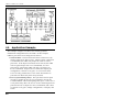
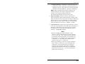
Front Panel
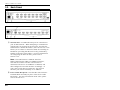
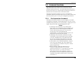
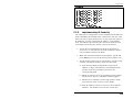
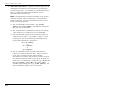
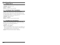
Figure 2.1: Instrument Front Panel (Model CMS-16 Shown)
À CLEAR: Restarts the CMS operating program without
changing user-selected parameter settings or breaking
port connections.
Á ON: Lights when AC Power is applied.
 SET: Used to Initialize the CMS to defaults specified by
the SetUp Switches. To initialize, press and hold both the
SET and CLEAR buttons, release only the CLEAR button,
wait for the Port LEDs to flash, and then release the
SET button.
Notes:
· During initialization, all port LEDs will flash ON
three times.
· During initialization, all command-selected
parameters will be cleared, and the CMS will
revert to the default parameters specified by the
Option Switches.
à RDY: (Ready) Flashes to indicate unit is operational.
Ä NET: Lights when a Network Connection is present.
Å ACTIVITY LEDs: Light to indicate data activity at the
corresponding port. The CMS-16 includes sixteen Activity
LEDs, and the CMS-8 includes eight Activity LEDs
2-1
CMS-16 / CMS-8 User's Guide
2.2.
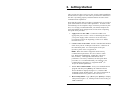
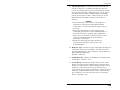
Back Panel
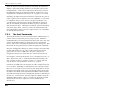
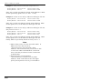
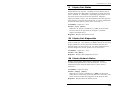
Figure 2.2: Instrument Back Panel (Model CMS-16)
Figure 2.3: Instrument Back Panel (Model CMS-8)
À Network Port: An RJ45 Ethernet port for connection to
your TCP/IP network. When attempting to communicate
with the unit via network for the first time, note that the
CMS features a default IP address (192.168.168.168). This
allows you to connect to the unit without first defining an
IP address (providing that the unit is being contacted by
another node on the same subnet.) For more information
on configuring the Network Port, please refer to
Section 5.5.4.
Note: The CMS features a 10BaseT Interface.
When connecting the CMS to a 100BaseT interface,
note that most router switches will autosense to
determine if the device is 100BaseT or 10BaseT, and
then configure the network interface accordingly. If
your router switch does not autosense, the network
interface port must be manually set to 10BaseT.
Á Power Cable Receptacle: Note that DC units include a
Terminal Block Assembly in place of the Power Cable
Receptacle. For more information on DC units, please
refer to Section 4.1.2.
2-2
Unit Description
 Power Switch
à RS232 PORTS: For connection to console ports on target
devices. Standard DB9 connectors configured as DTE
ports. The RS232 ports are similar to a serial port on a PC.
When connecting a modem, use a standard serial cable.
When connecting a PC or other DTE device use a null
modem cable.
· Ports 1 and 2 are System Setup Ports. Note that
Supervisor Level command access cannot be disabled at
these ports.
· Ports 1 and 2 can either be connected to a PC or modem.
Connection to a modem allows control by a remote PC.
Ä Option/SetUp Switches: A bank of eight DIP switches,
which set the default baud rate, handshake, message type,
and duplex mode. Switch functions are described in detail
in Section 4.2.
2-3
CMS-16 / CMS-8 User's Guide
2-4
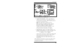
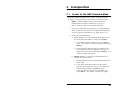
3. Getting Started
This section provides a brief overview of basic CMS capabilities,
and describes a simple test that can be performed to determine if
the unit is operating properly and demonstrate the unit's basic
communication capabilities.
Note that this Quick Start procedure is included only to provide a
quick demonstration of basic CMS capabilities. In order to take
full advantage of the complete range of features provided by this
unit, it is strongly recommended that you should complete the
entire Installation and Configuration sections after completing
the Quick Start procedure.
1. Apply Power to the CMS: Connect the CMS to an
appropriate power source. Prior to connecting the unit to
your power supply, make certain to review the safety
precautions listed at the beginning of this User's Guide,
and in Section 4.1.
2. Connect a PC to the CMS: Attach a standard null modem
cable from your PC COM port to the Port 1 connector on
the CMS back panel. For a description of the port
interface, please refer to Appendix A.
Note: When the CMS is shipped from the factory,
communication parameters are set as follows: 9600
bps, RTS/CTS Handshaking, 8 Data Bits, One Stop
Bit, No Parity. Although the CMS allows these
parameters to be easily redefined, for this Quick Start
procedure, it is recommended that you configure your
communications program (e.g. HyperTerminal â ) to
accept the default parameters.
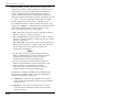
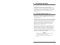
3. Access the Command Mode: Start your communications
program and then press [Enter]; the CMS Port Status
Screen should be displayed (Figure 3.1) and the CMS
command prompt should appear. For more information on
command mode access, please refer to Section 5.1.
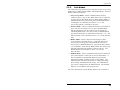
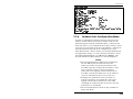
4. Review Help Menu: Type /H and press [Enter] to display
a help menu (Figure 3.2), which provides a basic listing of
CMS commands.
3-1
CMS-16 / CMS-8 User's Guide
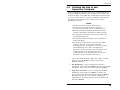
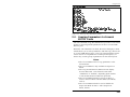
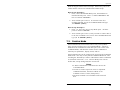
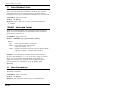
PORT STATUS:
Version 4.00,
Site ID: WESTERN_TELEMATIC_CALIFOR_IRVINE
PORT |
NAME
|
PASSWORD
| STATUS | MODE | BUFFER COUNT
-----+------------------+------------------+--------+--------+-------------01 | (undefined)
| (undefined)
| Free | Any
|
0
02 | (undefined)
| (undefined)
| Free | Any
|
0
03 | (undefined)
| (undefined)
| Free | Any
|
0
04 | (undefined)
| (undefined)
| Free | Any
|
0
05 | (undefined)
| (undefined)
| Free | Any
|
0
06 | (undefined)
| (undefined)
| Free | Any
|
0
07 | (undefined)
| (undefined)
| Free | Any
|
0
08 | (undefined)
| (undefined)
| Free | Any
|
0
|
|
|
|
|
09 | (undefined)
| (undefined)
| Free | Any
|
0
10 | (undefined)
| (undefined)
| Free | Any
|
0
11 | (undefined)
| (undefined)
| Free | Any
|
0
12 | (undefined)
| (undefined)
| Free | Any
|
0
13 | (undefined)
| (undefined)
| Free | Any
|
0
14 | (undefined)
| (undefined)
| Free | Any
|
0
15 | (undefined)
| (undefined)
| Free | Any
|
0
16 | (undefined)
| (undefined)
| Free | Any
|
0
Enter /H for command menu.
CMS>
Figure 3.1: The Port Status Screen (Model CMS-16, Defaults Shown)
5. Configure Network Port: In order to communicate with
the CMS via the network port, an IP Address, Subnet
Mask, and Gateway Address must be assigned to the unit .
At the CMS command prompt, type /N and press [Enter]
to display the Network Port Configuration Menu.
a) Note that the CMS features a default IP address
(192.168.168.168.) This allows you to initially
communicate with the unit via network (providing that
you are contacting the CMS from another node on the
same subnet), without first accessing the CMS
command mode in order to define an IP address.
However, when the CMS is installed in a working
network environment, it is recommended to define an
appropriate IP Address, Subnet Mask, and Gateway
Address as described in the steps that follow.
b) Settings for network parameters depend on the
configuration of your individual network. Please
contact your network administrator in order to
determine the appropriate settings for the IP Address,
Subnet Mask, and Gateway Address.
c) To assign network parameters, key in the number for
the desired parameter, press [Enter] and then follow
the instructions in the submenu. For example, to define
the IP Address, type 1 and press [Enter].
3-2
Getting Started
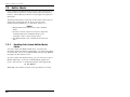
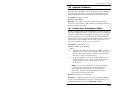
COMMAND MENU:
DISPLAY
/S[P]
/SD
/W[P] [n]
/J
/SN[P]
/H
Port Status
Port Diagnostics
Port Parameters (Who)
Site ID
Network Status
Command Menu (Help)
CONTROL
<Enter>
Enter Command Mode
/X
Exit Command Mode
/C <n> [n]
Connect - Local [Remote]
/D <n | Nn |...| *> Disconnect Port(s)
/E <n | ... | *>
Erase Buffer
/U
Send Parameter File
/T
Reset Network Interface
CONFIGURATION
/F
System Parameters
/P [n] Port Parameters
/N
Network Configuration
/I
Default and Test
/UF
Upgrade Firmware
/CP
Copy Port Parameters
+--------------------+
| P
Show Passwords |
| n
Port# or name |
| *
"all"
|
| |
"or"
|
| <> Required entry |
| [] Optional entry |
| Nn Telnet Port#
|
+--------------------+
/D, /E, /I, /T commands: add /Y to bypass "Sure (y/n)?"
CMS>
Figure 3.2: The Supervisor Level Help Screen
6. Connect Network Cable: Connect your 10BaseT or
100BaseT network interface to the CMS Network Port.
The Network Port is an RJ45, 10BaseT Ethernet jack, for
connection to a TCP/IP network.
Note: The CMS features a 10BaseT Interface.
When connecting to a 100BaseT interface, note that
most router switches will autosense to determine if
the device is 100BaseT or 10BaseT, and then
configure the network interface accordingly. If your
router switch does not autosense, the network
interface port must be manually set to 10BaseT.
7. Network Access: Telnet to the CMS's IP address. For
example, if the IP address is "1.2.3.4", on a UNIX system,
the Telnet command would be invoked as follows:
$ telnet 1.2.3.4 [Enter]
After the telnet connection is established, the CMS should
display the Port Status Menu, and the CMS command
prompt should appear, indicating that you have
successfully accessed the CMS command mode via the
Network Port.
This completes the introductory overview of the CMS. Please
proceed to Sections 4 and 5 for complete installation and
configuration procedures.
3-3
CMS-16 / CMS-8 User's Guide
3-4
4. Hardware Installation
4.1.
Connecting Power to the CMS Unit
The CMS is available in both AC and DC powered versions.
When connecting AC or DC power to the CMS, proceed as
follows:
CAUTIONS:
· This device should only be operated with the
type of power source indicated on the
instrument nameplate. If you are not sure of the
type of power service available, please contact
your local power company.
· Reliable earthing (grounding) of this unit must
be maintained. Particular attention should be
given to supply connections when connecting to
power strips, rather than directly to the branch
circuit.
4.1.1.
AC Powered Units
Plug the supplied power cable into the receptacle on the CMS
back panel, and then connect the power cable to an appropriate
grounded AC outlet. The CMS features a self adjusting power
supply that automatically adapts to power supplies between 90
and 250 VAC. Press the Power Switch ON. The ON LED should
light and the RDY LED should begin to flash.
4-1
CMS-16 / CMS-8 User's Guide
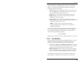
Figure 4.1: Terminal Block Assembly (DC Units Only)
4.1.2.
DC Powered Units
The DC terminal block features two bus inputs as shown in
Figure 4.1. This allows the user to connect only one DC power
source, or connect two DC power sources where the second
source functions as a backup. When connecting the CMS to your
DC power source, first remove the protective cover from the
terminal block, attach the wires from the -48V DC power source
to the screw terminals, connect your ground line to the labeled
ground screw, and then replace the protective cover.
4.2.
Configure Option Switches
When the CMS is shipped from the factory, the Option Switches
are configured for 9600 baud, 8 Bits-No Parity, RTS/CTS
handshaking, verbose command response, and command echo
ON (all switches Down). These settings are compatible with
most applications. If the default settings are not compatible with
your application, change the switch settings as follows.
The Option Switches should be configured to match the
parameters your control device will use when communicating
with the CMS. This will ensure access to command functions,
even if the unit is initialized to default parameters.
Notes:
· If the Option Switch configuration is changed, new
parameters will not take effect until the unit is
initialized as described in Section 4.3.
· Operating parameters (baud rate, parity, etc.) can
be selected for each port using the /P command as
described in Section 5.5. The /P command can
select different parameters for each CMS port.
· When the CMS is initialized, parameters will
return to settings specified by the Option Switches.
4-2
Hardware Installation
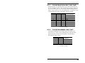
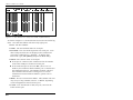
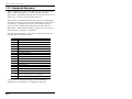
4.2.1.
Default Baud Rate (Sw1, Sw2, Sw3)
Option Switches one through three select the default baud rate
for all CMS RS232 Ports. The default baud rate must match the
rate your control device will use when communicating with the
CMS. If the control device will communicate via modem, select
a default baud rate that is compatible with the modem.
1
SW
2
3
Default Baud Rate
D
D
D
9600*
U
D
D
300
D
U
D
1200
U
U
D
2400
D
D
U
19.2K
U
D
U
38.4K
D
U
U
57.6K
U
U
U
115.2K
* = Factory Setting
4.2.2.
Default Handshake (Sw4, Sw5)
The default handshake format must match the format your
control device will use when communicating with the CMS.
Option Switches 4 and 5 can select RTS/CTS (hardware),
XON/XOFF, Both or None.
Switch
4
5
Default
Handshake
D
D
RTS/CTS *
U
D
XON/XOFF
D
U
Both
U
U
None
* = Factory Setting
4-3
CMS-16 / CMS-8 User's Guide
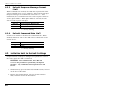
4.2.3.
Default Response Message Format
(Sw6)
When commands are invoked, the CMS can respond with either
verbose (English text) or terse (numeric / abbreviated) messages.
Response messages are summarized in Section 11.2. After
installation, the /P command can also set the response format to
"none" (Quiet Mode). When Quiet Mode is selected, the unit
will not send response messages.
Switch 6
D
Default Response Message Type
Verbose (English Text) *
U
Terse (abbreviated / numeric)
* = Factory Setting
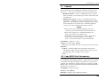
4.2.4.
Default Command Echo (Sw7)
Switch Seven enables or disables the Command Echo. When
enabled, characters sent to the CMS will be echoed back to the
control device.
Switch 7
D
Default Command Echo
Enable*
U
Disable
* = Factory Setting
4.3.
Initialize Unit to Default Settings
If Option Switch settings are changed, new parameters will not
take effect until the CMS is initialized.
CAUTION: After initialization, the CMS will
revert to the parameters specified by the Option
Switches. Any command-selected parameters will
be lost.
1. Simultaneously press the SET and CLEAR buttons, located
on the face of the CMS.
2. Release the CLEAR button, wait for the Port LEDs to
flash, and then release the SET button.
4-4
Hardware Installation
4.4.
Connecting the Network Cable
The CMS Network Port is an RJ45, 10BaseT Ethernet Jack, for
connection to a TCP/IP network. Connect your 10BaseT or
100BaseT network interface to the CMS-32 Network Port.
The CMS features a default IP Address (192.168.168.168.)
Providing that you are communicating with the unit from a node
on the same subnet, this allows you to initially contact the CMS
without first accessing the CMS command mode to define an IP
address.
Note however, that when installing the CMS in a working
network environment, it is strongly recommended to assign the
IP Address, Gateway Address, and Subnet Mask as described in
Section 5.5.4.
Note: The CMS features a 10BaseT Interface.
When connecting the CMS to a 100BaseT interface,
note that most router switches will autosense to
determine if the device is 100BaseT or 10BaseT, and
then configure the network interface accordingly. If
your router switch does not autosense, the network
interface port must be manually set to 10BaseT.
4.5.
Connecting Devices to the CMS
1. Determine which CMS port will be used for connection to
the new device (e.g. Port 3).
2. Use an appropriate DB9 cable to connect the RS232 serial
port on the device to a DB9 port on the CMS.
a) External Modems and other DCE Devices: Use a
standard serial modem cable.
b) PCs and other DTE Devices: Use a standard null
modem cable.
3. Access the CMS command mode and then select
communication parameters for each CMS port as described
in Section 5.5.
4-5
CMS-16 / CMS-8 User's Guide
Figure 4.2: CMS Application Example (Model CMS-16 Shown)
4.6.
Application Example
The example in Figure 4.2 shows one of many possible
installation configurations for the CMS. In this example,
CMS-16 ports have been configured as follows:
· Network Port: The Network Port allows telnet access by
remote Supervisors and/or Users. When a telnet connection
is established, the CMS will prompt the caller to enter a
password. If the Supervisor Password is entered, the CMS
will recognize Supervisor Level Commands; if a Port
password is entered, the CMS will only recognize User
Level Commands. Supervisors are allowed to adjust port
configuration, connect to any port, or review unit status.
Users are only permitted to review status and connect to
ports that are allowed by their Port password.
· Port 1 (System SetUp Port): This port has been left open
in order to permit on-site service personnel to access the
Command Mode without disrupting other ports. Since Port 1
is a System SetUp Port, the service tech is allowed password
protected access to Supervisor Level commands, and is able
to connect to any port, change configuration, or display unit
status.
4-6
Hardware Installation
· Port 2 (Modem Port): An external modem has been
installed at Port 2. This port has also been configured for
Modem Mode, which allows definition of a modem reset
string, initialization string, and hang-up string. When a
caller contacts the CMS unit via modem, a password prompt
will be displayed. If the Supervisor Password is entered, the
CMS will permit access to Supervisor Level Commands; if a
Port password is entered, the CMS will only recognize User
Level Commands. Supervisors are allowed to adjust port
configuration, connect to any port, or review unit status.
Users are only allowed to review status and connect to the
ports allowed by their Port Password.
· Ports 5, 7, and 9 (User Ports): The Port Password
“COLOCATION1” has been assigned to these three ports.
If the CMS is contacted via the Network Port or Modem
Port, and this password is entered at log in, User’s will only
be able to review status and connect to the devices attached
to Ports 5, 7, and 9.
· Ports 12, 14, and 16 (User Ports): The Port Password
“COLOCATION2” has been assigned to these three ports. If
the CMS is contacted via the Network Port or Modem Port,
and this password is entered at log in, User’s will only be
able to review status and connect to the devices attached to
Ports 12, 14, and 16.
Note that in this example, Ports 3 through 16 could also be a
mixture of ports connected to external modems, and ports
connected to devices such as file servers or archives. This would
allow remote users to dial in and access a specific file server or
archive after entering a valid Port Password at log in.
4-7
CMS-16 / CMS-8 User's Guide
4-8
5. Configuration
5.1.
Access to the CMS Command Mode
When the CMS Command Mode is active, commands can be
invoked to select parameters, and connect or disconnect ports.
Note: Command Mode cannot be accessed from a
Buffer Mode Port, Passive Mode Port, or any port
that is currently connected to another CMS port.
1. Start your communications program (e.g. HyperTerminal).
Make certain the CMS and your communications program
are set for the same parameters (e.g. baud, parity, etc.).
2. Access the Command Mode.
a) Local Access: To access command mode from a local
PC connected to the CMS via cable, press [Enter].
i.
If you have already hit other keys, press [Enter]
twice. There must be no other characters preceding
[Enter].
ii. If the Supervisor Password has been defined, the
password prompt will be displayed. Key in your
Supervisor or Port password and press [Enter]. The
"CMS>" prompt will appear.
b) Modem Access: To access the command mode via
modem, proceed as follows:
i.
Dial the number for the external modem connected
to the CMS.
ii. If you have defined the Supervisor Password, a
prompt will be displayed. Key in your Supervisor
or Port password and press [Enter]. If the
Supervisor Password has not been defined, just
press [Enter]. The "CMS>" prompt will appear.
5-1
CMS-16 / CMS-8 User's Guide
c) Network Access: The CMS includes a default IP
Address (192.168.168.168), which allows you to
contact the unit from any network node on the same
subnet. When the CMS is installed in a working
network environment, it is recommended that you
redefine the IP Address, Subnet Mask and Gateway
Address as described in Section 5.5.4. To contact the
CMS via network, proceed as follows:
i.
Telnet to the CMS’s IP Address. For example, if the
IP Address is “1.2.3.4”, on a UNIX system, the
Telnet command would be invoked as follows:
$ telnet 1.2.3.4 [Enter]
ii. Note that if the Telnet connection is refused, this
may mean that either the IP Security feature (see
Section 5.5.5) has denied the connection, or the unit
is operating on a 100BaseT network that does not
autosense for 10BaseT devices (see Section 4.4).
iii. If the Supervisor Password has been defined, the
password prompt will be displayed. Key in your
Supervisor or Port password and press [Enter]. The
CMS will display the Port Status Screen, and then
the "CMS>" prompt will appear.
Note: In addition to standard telnet connections to
ports 23, 2001, and 3001, the CMS also allows telnet
users to specify an optional telnet port number in order
to connect to a specific RS-232 port. Telnet users can
also connect using either standard telnet protocol, or
"raw socket mode". For more information regarding
other telnet port numbers, please refer to Section 8.2.
5.2.
System SetUp Ports
Ports 1 and 2 are designated as System SetUp Ports, and will
always permit password protected access to Supervisor Level
commands, even if the unit is reset to default parameters.
In order to ensure that access to command functions is always
available, Ports 1 and 2 cannot be configured as Buffer Mode or
Passive Mode Ports. Buffer and Passive Mode Ports are not able
to access the Command Mode. In addition, Ports 1 and 2 always
permit password protected access to Supervisor commands; the
Supervisor Mode cannot be disabled at these two ports.
5-2
Configuration
5.3.
Password Functions
The CMS features three different types of passwords; the
Supervisor Password, the Port (User) Passwords, and the
Outbound Telnet Passwords. The Outbound Telnet Password is
discussed in Section 8.4, and the Supervisor Password and User
Passwords are discussed in the sections that follow.
The Supervisor Password allows access to configuration
commands, and Port Passwords allow users to create connections
between specific ports or view port configuration parameters.
5.3.1.
The Supervisor Password
The Supervisor Password allows access to higher level CMS
configuration commands, which administrators can use to select
communication parameters, set up IP Security, assign port access
rights, and perform other system management tasks.
Notes:
· If the Supervisor Password is not defined, then
Supervisor Level commands will be available to all
ports, and port access and configuration functions
will not be password protected. If you wish to
prevent user ports from changing unit
configuration, or connecting to restricted ports, the
Supervisor Password must be defined.
· If the Supervisor Password is defined, the CMS
will display a password prompt when you attempt
to access command mode. Any RS232 port that
has not been assigned a Port Password, can then
only be accessed using the Supervisor Password.
· If the CMS is reset to default parameters, all ports
will revert to the default state, where Supervisor
Level commands are available to all ports, without
password protection.
· When defining a Supervisor Password, it is
strongly recommended that you record the
password for future use. If you forget or lose your
Supervisor Password, you will not be able to
access Supervisor Level Commands. In this case,
the only way to access the Supervisor Mode, is to
reinitialize the CMS to default values as described
in Section 4.3.
5-3
CMS-16 / CMS-8 User's Guide
After the Supervisor Password has been defined, the CMS will
display a password prompt whenever you attempt to access the
command mode. If the correct Supervisor Password is entered,
the CMS then starts up in Supervisor Mode. Supervisor Level
commands are summarized in Section 11.3 of this User’s Guide.
Normally, the Supervisor Password can be entered at any port in
order to gain access to Supervisor Level commands. If you wish
to completely deny a port’s access to Supervisor Mode (even
with the Supervisor Password), the Port Parameters menus (/P
and /N) can disable the Supervisor Mode at ports 3 and above,
and the Network Port. The Supervisor Mode cannot be disabled
at System SetUp Ports 1 and 2, or at the one inbound Network
Port which always allows access to Supervisor Level commands,
as described in Section 8.1.
5.3.2.
The Port Passwords
The Port Passwords (or User Passwords) allow administrators to
restrict access to a specific port or group of ports. When the
command mode is accessed with a Port Password, users may only
connect to the RS232 Ports to which they have been granted
access, and review configuration parameters for those ports. Port
Passwords do not grant access to CMS configuration commands.
The port configuration menus are used to assign a Port Password
to each individual port. In order to allow a Port Password to
grant access to several CMS ports, the same password is
assigned to each port to which the user will be allowed access.
For example, if the Port Password “test” is assigned to ports 3, 4,
and 6, then when “test” is entered at the Password Prompt, the
user will only be able to connect to ports 3, 4, and 6, and will
only be able to view parameters for ports 3, 4, and 6.
If desired, all CMS ports can function as either a Supervisor Port
or a User Port, depending on which password is entered at login.
However, if you wish to prevent a port from being able to access
the Supervisor Mode at all (even with the Supervisor Password),
the Supervisor Mode can be disabled at the RS232 Ports and the
Network Port using the Port Configuration menus as described in
Section 5.5. Note however, that the Supervisor Mode cannot be
disabled at RS232 Ports 1 and 2, or at the one network port that
always allows access to Supervisor Level commands (see
Section 8.1.)
5-4
Configuration
5.4.
Defining the Site ID and
Supervisor Password
Before configuring individual ports, the Site ID and Supervisor
Password should be defined. The Site ID is used to denote the
location or name of the CMS unit, and the Supervisor Password
is used to restrict access to sensitive commands. Both the Site
ID and Supervisor Password are defined via the System
Parameters menu (/F).
Notes:
· The Site ID cannot include double quotes.
· The Supervisor Password cannot include an
asterisk, forward slash, spaces, or double quotes.
· Both the Site ID and Supervisor Password will be
cleared if the CMS is initialized to default settings.
· The Supervisor Password cannot be the same as an
existing Port Password.
· The System Parameters Menu is only available in
Supervisor Mode.
· The Supervisor Password is case sensitive. Make
certain to note the exact password entered,
including the case of each letter. It is also strongly
recommended to write down your Supervisor
Password. If the password is lost or forgotten, you
will not be able to access Supervisor Level
commands unless you initialize the unit and clear
all parameters as described in Section 4.3.
1. Access the command mode. When the “CMS>” prompt
appears, type /F [Enter] to display the System
Parameters Menu.
2. Site ID Message: (Up to 32 characters; Default =
undefined) Type 1 and press [Enter], the Site I.D. Prompt
will appear. Key in the desired text and press [Enter] .
3. Supervisor Password: (Up to 32 characters; Default =
undefined) Type 2 and press [Enter], a prompt will
appear. Key in the desired password then press [Enter].
The CMS will prompt you to confirm spelling and
capitalization. Key in the password a second time, and
then press [Enter].
5-5
CMS-16 / CMS-8 User's Guide
5.5.
Port Configuration
5.5.1.
Configuration Conventions
When responding to prompts, invoking commands, and selecting
items from the port configuration menus, note the following:
· To select an item from a Port Configuration menu, key in the
number for the item and press [Enter].
· To clear an item in a Port Configuration menu, enter the
number for the desired item and press [Enter]. When the
prompt appears, press [Space] and then press [Enter].
· The Port Name cannot include the forward slash character
( /), double quotes ("), the asterisk character (*), or
blank spaces.
· Port Names must begin with an alphabetic character; Port
Names cannot begin with a number, punctuation character or
symbol.
· A Port cannot be named “N1” through "N19", these names
are reserved for the logical Network Ports.
· Refer to the instructions in each screen for additional
functions available under that screen.
· To exit a menu or prompt without changing its current value,
press [Esc].
· Passwords and port names are case sensitive. When defining
passwords and port names, note the exact text, including the
case of each character.
· The “Who” command (/W) can be used to display currently
selected parameters for your resident port. Note that when
the Network port has been accessed using a Port Password
(User Mode), the /W command will only display the settings
for the Sequence Disconnect, the selected Logoff Character
and the current status of the "Accept Break" feature and the
"Discard <LF> After <CR>" option.
· If you are configuring the CMS unit via modem, modem
communication parameters will not be changed until after
you exit from command mode and disconnect from the
CMS unit.
· If you are configuring the CMS via network, network
communication parameters will not be changed until all
telnet connections to the CMS have been terminated
(including the connection that was used to enter the new
parameters.)
5-6
Configuration
5.5.2.
Port Modes
The CMS offers four different port operation modes; Any-to-Any
Mode, Passive Mode, Buffer Mode, and Modem Mode. The Port
Modes function as follows:
· Any-to-Any Mode: Allows communication between
connected ports. Any-to-Any Mode Ports can be connected
to other Any-to-Any Mode, Passive Mode, Buffer Mode, or
Modem Mode Ports by accessing the Command Mode and
invoking the /C command (see Section 7.1.1). The
Any-to-Any Mode is available to all ports.
· Passive Mode: Allows communication between connected
ports, but does not allow access to the Command Mode.
Passive Mode Ports can be connected by accessing the
Command Mode from a free Any-to-Any or Modem Mode
port and invoking the /C command (see Section 7.1.1). The
Passive Mode is not available to Ports 1 or 2 or the Network
Port.
· Buffer Mode: Allows collection and storage of data
received from connected devices. Collected data can be
retrieved by accessing the Command Mode from a free
Any-to-Any or Modem Mode Port, and issuing the Connect
(/C) Command. Note that the Buffer Mode also allows passthrough communication with the connected device. The
Buffer Mode is not available to Ports 1 or 2 or the
Network Port.
· Modem Mode: Allows communication between connected
ports and simplifies connection to an external modem. A
port configured for the Modem Mode can perform all
functions normally available in Any-to-Any Mode. The
Modem Mode also allows definition of a Hang-Up String,
Reset String, and Initialization String. Any CMS RS232
port can be configured for the Modem Mode. The Modem
Mode is not available at the Network Port.
For more information on Port Modes, please refer to Section 7.
5-7
CMS-16 / CMS-8 User's Guide
PORT PARAMETERS #02:
1.
2.
3.
4.
5.
6.
7.
8.
9.
10.
11.
12.
13.
14.
Port Name:
Password:
Baud Rate:
Bits/Parity:
Stop Bits:
Handshake Mode:
Port Mode:
74. DTR Output:
Supervisor Mode:
Logoff Character:
Sequence Disconnect:
Timeout Disconnect:
Response Type:
Command Echo:
Accept Break:
PORT_02
(defined)
9600
8-None
1
RTS/CTS
Any-to-Any
Pulse
Permit
^X
One Character
Off
Verbose
On
On
15. Direct Connect:
Telnet Port:
Raw Port:
On - Password
2102
3102
Enter: "<" previous port,
">" next port,
<ESC> exit ...
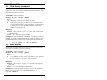
Figure 5.1: Port Configuration Menu (Port 2 Shown)
5.5.3.
RS232 Port Configuration Menus
The Port Configuration Menus are used to select options for each
of the CMS RS232 ports. Parameters selected via these menus
will stay in effect until the unit is initialized or the /P command
is used to reconfigure the port. After initialization, parameters
will revert to the defaults specified by the Option Switches.
To select port parameters, proceed as follows:
1. Access the Command Mode. If the password prompt is
displayed, key in your Supervisor Level Password.
2. Type /P, followed by the number of the port to be
configured, and press [Enter]. For example, to configure
Port 2, type /P 2 [Enter]. The Port Configuration menu
will appear (Figure 5.1).
a) If the /P Command is entered at an RS232 port without
including the port number in the command line (e.g. /P
[Enter]), the configuration menu for your resident port
will be displayed.
b) If the /P Command is entered at the Network port,
without including the port number in the command line,
this will produce an "Invalid Parameter" response.
c) The /P command is only available in Supervisor Mode.
5-8
Configuration
The Port Configuration menu offers the following options:
1. Port Name: (Up to 16 characters, Default = undefined).
Notes:
· The Port Name cannot include the forward slash
character (/), double quotes ("), the asterisk
character (*), or blank spaces.
· Port Names must begin with an alphabetic
character; Port Names cannot begin with a number,
punctuation character or symbol.
· A Port cannot be named “N1” through "N19", these
names are reserved for the logical Network Ports.
2. Password: (Up to 16 characters) Defines the Port
Password for this port. Note that identical Port Passwords
are generally assigned to several ports. When this
password is entered at the login prompt, the user will then
have access to all ports that share this password.
(Default = undefined).
Notes:
· The Port Password is not displayed by the Port
Parameters menu. When the Port Password has
been defined, the field for this item will read
“defined”. To display Port Passwords, invoke the
/SP or /WP commands as described in Section 6.
· The CMS will not allow you to define a Port
Password that is the same as the existing
Supervisor Password.
3. Baud Rate: Selects the baud rate for the port. Can be set
to any standard rate from 300 bps to 115.2K bps.
(Default = Selected By Option Switches 1, 2, and 3)
4. Bits/Parity: (Default = 8-None).
5. Stop Bits: (Default = 1).
6. Handshake Mode: Selects the handshake format for this
port; XON/XOFF, RTS/CTS (hardware), Both, or None.
(Default = RTS/CTS).
5-9
CMS-16 / CMS-8 User's Guide
PORT PARAMETERS #02:
1.
2.
3.
4.
5.
6.
7.
8.
9.
10.
11.
12.
13.
14.
Port Name:
Password:
Baud Rate:
Bits/Parity:
Stop Bits:
Handshake Mode:
Port Mode:
71. Reset String:
72. Init String:
73. Hang-Up String:
Supervisor Mode:
Logoff Character:
Sequence Disconnect:
Timeout Disconnect:
Response Type:
Command Echo:
Accept Break:
PORT_02
(defined)
9600
8-None
1
RTS/CTS
Modem
ATZ
AT&C1&D2S0=1
(undefined)
Permit
^X
One Character
15 Min
Verbose
On
On
15. Direct Connect:
Telnet Port:
Raw Port:
On - Password
2102
3102
Enter: "<" previous port,
">" next port,
<ESC> exit ...
Figure 5.2: Port Parameters Menu (Modem Mode)
7. Port Mode: Defines the operation mode for this port.
Note that Ports 1 and 2 cannot be configured for Passive
Mode or Buffer Mode. (Default = Any-to-Any Mode).
When Any-to-Any, Passive, or Buffer Mode is selected, the
unit will display the DTR Output prompt (Figure 5.1).
This prompt is not displayed when Modem Mode is
selected.
74. DTR Output: Determines how the DTR line will react
when this port disconnects. The DTR line can be held
low, high, or pulsed for 0.5 seconds and then held high.
In the default state, the DTR line will pulse for 0.5
seconds and then remain high. For more information,
please refer to Appendix A. (Default = Pulse).
When Port Mode (menu Item 7) is set to Modem Mode, the
menu will include additional prompts (see Figure 5.2),
which are used to define the following:
71. Reset String: If necessary, this prompt can be used to
re-define the modem reset string. The Reset String is
sent prior to the Initialization string. (Default = ATZ).
72. Initialization String: Defines a command string that
is sent to initialize a modem to settings required by
your application. (Default = AT&C1$D2S0=1).
5-10
Configuration
73. Hang-Up String: Although the CMS will pulse the
DTR line in order to hang-up an attached modem, the
Hang-Up string is often useful for controlling modems
that do not use the DTR line. (Default = undefined).
Note: When communicating with the CMS unit via
modem, parameters will not be changed until after
you have exited from command mode and
discontinued the modem connection to the unit.
8. Supervisor Mode: Permits or denies port access to
Supervisor Mode. When enabled (Permit), and the valid
Supervisor Password is entered, the port will be allowed to
invoke Supervisor Level commands. If disabled (Deny),
the port may not enter Supervisor Mode, even when the
Supervisor Password is entered. (Default = Permit).
9. Logoff Character: Defines the Logoff Character for this
port. The Logoff Character determines the command(s) or
character(s) that must be issued at this port in order to
disconnect from a second port (Resident Disconnect).
(Default = ^X ([Ctrl] plus [X]))
Note:
· When redefining the Logoff Character, make
certain to select a character that does not normally
occur in your data. This will prevent the unit from
accidentally disconnecting ports in the middle of a
data transfer. For example, if the Logoff Character
is defined as "s", then the ports will disconnect
whenever the letter "s" is detected.
· The Logoff Character cannot be used to terminate a
telnet "Direct Connection" or an outbound Telnet
connection. Direct Connections are terminated
using the telnet program's disconnect command.
And outbound Telnet connections are terminated as
described in Section 8.4.3. For more information,
please refer to Section 8.
5-11
CMS-16 / CMS-8 User's Guide
10. Sequence Disconnect: Enables/Disables and configures
the Resident Disconnect command. This prompt offers the
option to either disable the Sequence Disconnect, select a
one character format, or select a three character format.
(Default = One Character). Note the following:
n When a Resident Connection is initiated, the CMS will
send a message which lists the connected ports, and
displays the one character or three character disconnect
command required in order to terminate the connection.
n The One Character Disconnect sequence is intended for
situations where the destination port should not receive
the disconnect command. When the Three Character
format is selected, the disconnect sequence will pass
through to the destination port prior to breaking the
connection.
n When the Three Character format is selected, the
Resident Disconnect Sequence will use the format
"[Enter]LLL[Enter]", where L is the selected Logoff
Character.
n When the One Character format is selected, resident
connections are terminated by entering the selected
Logoff Character only. There is no need to press [Enter]
before and after the Logoff Character when the One
Character format is selected.
5-12
Configuration
11. Timeout Disconnect: Enables and selects the Timeout
Period for this port. If enabled, and the port does not
receive or transmit data for the specified Timeout Period,
the port will disconnect. When the port is set for Any-toAny Mode, Passive Mode, or Buffer Mode, the default
setting for this item is “OFF”. When the port is set for
Modem Mode, the default setting for this item is 15
minutes.
Notes:
· The Timeout Disconnect value is also applied to
telnet Direct Connections and outbound Telnet
connections. For more information, please refer to
Section 8.
· The Timeout Disconnect is also applied to nonconnected ports that are left in Command Mode. If
the timeout feature is enabled, and no additional
data activity is detected, an unconnected port will
exit from command mode when the Timeout
Disconnect value expires.
· When two connected ports time out and are
disconnected, both ports will also exit from
Command Mode.
12. Response Type: Selects the type of messages that this port
will send in response to commands. The user can select
Verbose (English Text), Terse (Numeric / Abbreviation), or
Quiet Mode (No Response).
(Default = Verbose).
13. Command Echo: Enables or Disables the command echo
for this port. (Default = On).
14. Accept Break: Determines whether the port will accept
breaks received from the attached device, and pass them
along to a connected port. When enabled, breaks received
at this port will be passed to any port that this port is
connected to, and sent along to the device connected to the
other port. When disabled, breaks will be refused at this
port, and hence, not sent to the other port or connected
device. (Default = Yes)
5-13
CMS-16 / CMS-8 User's Guide
15. Direct Connect: Enables/Disables and configures the
telnet Direct Connect feature at this port. Direct Connect
allows users to access the CMS unit and automatically
create a connection between the Network Port and a
specific CMS RS232 port by including the appropriate
telnet port number in the telnet connect command (e.g. Port
5 = 2105). For more information on the Direct Connect
feature, please refer to Section 8.2. (Default = Off)
To configure the Direct Connect feature at this port, type
15 and press [Enter]. A submenu will be displayed, which
offers three different Direct Connect options: "Off",
"On - No Password" and "On - Password".
• Off: Telnet users will not be able to employ the Direct
Connect feature to connect to this port.
• On - No Password: Telnet users will be able to employ
the Direct Connect feature to connect to this port without
entering a password.
• On - Password: Telnet users will be able to employ the
Direct Connect feature to connect to this port, but they
will be required to enter a password before the
connection is established.
Notes:
· If "On - Password" is selected and the Supervisor
Mode is disabled (Deny) at the Network Port, then
the Port Password must be entered in order to
establish a direct connection with this port.
· If "On - Password" is selected and the Supervisor
Mode is enabled (Permit) at the Network Port, then
either the Supervisor Password or the Port
Password may be entered in order to connect to
establish a direct connection with this port.
In addition to enabling, disabling, and configuring the
Direct Connect feature, Item 15 also lists both Direct
Connect port numbers for this port.
a) Telnet Port: The telnet port number that is used to
create a Direct Connection to this port using standard
telnet protocol.
b) Raw Port: The telnet port number that is used to
create a Direct Connection to this port using "Raw
Socket" protocol.
5-14
Configuration
NETWORK CONFIGURATION:
NETWORK PARAMETERS
1. IP Address:
2. Subnet Mask:
3. Gateway Address:
4. IP Security
65.106.93.107
255.255.255.0
65.106.93.97
Off
TELNET PORT PARAMETERS
11. Supervisor Mode (except 2001):
12. Logoff Character:
13. Sequence Disconnect:
14. Timeout Disconnect:
15. Response Type:
16. Command Echo:
17. Accept Break:
18. Discard <LF> after <CR>:
19. Password:
Permit
^X
One Character
Off
Verbose
On
On
Off
(undefined)
*: These parameters are installed when all Telnet connections are inactive.
Enter: #<CR> to change,
<ESC> exit ...
Figure 5.3: Network Parameters Menu (Supervisor Mode Only)
5.5.4.
Network Port Configuration Menu
In order to communicate with the CMS via network, the IP
Address, Subnet Mask, and Gateway Address must first be
defined using the Network Parameters Menu. If desired, this
menu also allows you to implement IP Security features, which
can restrict access based on the user’s IP Address. Settings for
network parameters depend on the configuration of your
individual network. Please contact your network administrator
for appropriate settings. To select network parameters, access
the CMS Command Mode, type /N and press [Enter]. The
Network Parameters Menu (Figure 5.3) will be displayed.
Notes:
· The Network Parameters Menu selects parameters
for all CMS logical Network Port Ports (the
CMS-16 provides 19 logical Network Ports, and
the CMS-8 provides 9 logical Network Ports.) The
only exception is Item 11 (Supervisor Mode),
which will not be applied to Network Port N9 on
the CMS-8, and Network Port N17 on the CMS-16
(for more information, please see Section 8.1.)
· Although new parameters can be specified via
network connection, new parameters will not be
applied until all telnet connections to the CMS
(including the connection that was used to enter the
parameters) are terminated.
· The Network Parameters menu is only available in
Supervisor Mode.
5-15
CMS-16 / CMS-8 User's Guide
The Network Parameters menu offers the following options:
1. IP Address: Defines the IP Address for the CMS unit.
Type 1 press [Enter], and follow the instructions in the
submenu. (Default = 192.168.168.168).
2. Subnet Mask: Defines the Subnet Mask for the CMS unit.
Type 2 press [Enter], and follow the instructions in the
submenu. (Default = undefined)
3. Gateway Address: Defines the Gateway Address for the
CMS unit. Type 3 press [Enter], and follow the
instructions in the submenu. (Default = undefined).
4. IP Security: Sets up the IP Security feature as described
in Section 5.5.5.
11. Supervisor Mode (Port 23): Permits or denies access to
the Supervisor Mode. When enabled (Permit), and the
valid Supervisor Password is entered, this port may then
issue Supervisor level commands. If disabled (Deny), the
port may not enter Supervisor Mode, even when the
Supervisor Password is entered. (Default = Permit).
Note: In order to ensure that remote administrators
will always be able to access Supervisor Level
commands via network, the Supervisor Mode will not
be disabled at Port N17 on the CMS-16, and Port N9
on the CMS-8 (for more information, please refer to
Section 8.1.)
12. Logoff Character: Defines the Logoff Character for the
Network Port. The Logoff Character determines the
command(s) or character(s) that must be issued at this port
in order to disconnect from a second port (Resident
Disconnect). (Default = ^X ([Ctrl] plus [X])).
Note: The Logoff Character cannot be used to
terminate a telnet "Direct Connection" or outbound
Telnet connection. For more information, please
refer to Section 8.
5-16
Configuration
13. Sequence Disconnect: Enables/Disables and configures
the Resident Disconnect command. This prompt offers the
option to either disable the Sequence Disconnect, select a
one character format, or a three character format.
(Default = One Character). Note the following:
· When a Resident Connection is initiated, the CMS will
send a message which lists connected ports, and displays
the one character or three character disconnect command
that will be required in order to terminate the connection.
· The One Character Disconnect is intended for situations
where the destination port should not receive the
disconnect command. When the Three Character format
is selected, the disconnect sequence will pass through to
the destination port prior to breaking the connection.
· When Three Character format is selected, the Resident
Disconnect uses the format “[Enter]LLL[Enter]”, where
L is the selected Logoff Character.
· When the One Character format is selected, resident
connections are terminated by entering the selected
Logoff Character only. There is no need to press [Enter]
before and after the Logoff Character when the One
Character format is selected.
14. Timeout Disconnect: Enables and selects the Timeout
Disconnect for the Network Port. If enabled, and the port
does not receive or transmit data for the specified time
period, the port will disconnect. (Default = 5 Minutes).
Note: The Timeout Disconnect value is also applied
to Telnet Direct Connections and outbound Telnet
connections. For more information, please refer to
Section 8.
15. Response Type: Selects the type of messages that the port
will send in response to commands. The user can select
Verbose (English Text), Terse (Numeric / Abbreviation), or
Quiet Mode (No Response). (Default = Verbose).
16. Command Echo: Enables or Disables the command echo
for the Network Port. (Default = On).
5-17
CMS-16 / CMS-8 User's Guide
17. Accept Break: Determines whether the port will accept
breaks received from the attached device, and pass them
along to a connected port. When enabled, breaks received
at this port will be passed to any port that this port is
connected to, and sent along to the device connected to the
other port. When disabled, breaks will be refused at this
port. (Default = Yes)
18. Discard <LF> after <CR>: If desired, this option can be
used to discard the Line Feed character that is often
produced by telnet software. When this parameter is
enabled, the <LF> character sent after the <CR> will not
be forwarded to the serial port that the telnet connection is
in session with. When the status of this parameter is
changed the new setting will take effect immediately, thus
changing all current, active connections. This parameter
applies to all CMS telnet connections. (Default = Off)
19. Password: Defines the optional password for outbound
Telnet connections. Note that if this password is not
defined, then only the Supervisor Mode be able to initiate
an outbound Telnet connection. For more information on
outbound telnet connections, please refer to Section 8.4.
(Default = undefined).
Notes:
· The outbound Telnet password can either be set to
match any User Mode password, or it can be
different from existing User Mode Passwords.
· If the outbound Telnet password is the same as a
User Mode password, then only that user may
initiate an outbound Telnet connection.
· If the outbound Telnet password is different from
all User Mode passwords, then any user can initiate
an outbound Telnet connection, but they must first
logoff from the CMS command mode, and then relogin using the currently defined outbound Telnet
password.
5-18
Configuration
IP SECURITY:
1.
2.
3.
4.
5.
6.
7.
8.
9.
10.
Security Mask #1:
Mask #1 Action:
Security Mask #2:
Mask #2 Action:
Security Mask #3:
Mask #3 Action:
Security Mask #4:
Mask #4 Action:
Security Mask #5:
Mask #5 Action:
Enter:
(undefined)
Permit
(undefined)
Permit
(undefined)
Permit
(undefined)
Permit
(undefined)
Permit
#<CR> to Select Menu,
<ESC> for Previous Menu ...
Figure 5.4: IP Security Menu
5.5.5.
Implementing IP Security
The CMS can be configured to restrict unauthorized IP addresses
from establishing an inbound telnet connection to the unit. This
allows the user to grant Telnet access to only a specific group of
IP addresses, or block a particular IP address. In the default
state, the CMS accepts incoming IP connections from all hosts.
To configure the IP Security feature, proceed as follows:
1. Access the Network Parameters menu as described in
Section 5.5.4. Note that the Network Parameters menu is
only available in Supervisor Mode.
2. When the Network Parameters menu appears, type 4 and
press [Enter] to access the IP Security menu (Figure 5.4).
3. The IP Security Menu lists five IP Security “masks” along
with the selected permit/deny action for each mask.
a) Each Security Mask prompt defines a specific IP
address or range of IP addresses. Each Mask Action
prompt selects the permit/deny action for the
corresponding mask.
b) Masks are listed in order of ascending priority; Mask 1
has the lowest priority, and Mask 5 has the highest.
c) Masks have a cumulative effect; high priority masks
supersede the effect of lower priority masks.
d) Each IP Address consists of a series of four eight bit
numbers. The number 255 is used as a wild card.
5-19
CMS-16 / CMS-8 User's Guide
Example 1: Deny access to all hosts except 192.1.1.5:
Security Mask #1: 255.255.255.255
Security Mask #2: 192.1.1.5
Mask #1 Action: Deny
Mask #2 Action: Permit
Since 255 is a wild card, Mask #1 blocks all IP Addresses. Mask
#2 then specifically grants access to 192.1.1.5 only.
Example 2: Allow access only by addresses that begin with 192:
Security Mask #1: 255.255.255.255
Security Mask #2: 192.255.255.255
Mask #1 Action: Deny
Mask #2 Action: Permit
Since 255 is a wild card, Mask #1 blocks all IP addresses Mask
#2 then grants access to all addresses that begin with 192.
Example 3: Allow access only by addresses that begin with 192,
deny access to 192.1.1.5.
Security Mask #1: 255.255.255.255
Security Mask #2: 192.255.255.255
Security Mask #3: 192.1.1.5
Mask #1 Action: Deny
Mask #2 Action: Permit
Mask #3 Action: Deny
Since 255 is a wild card, Mask #1 blocks all IP addresses. Mask
#2 then grants access to all addresses that begin with 192.
Finally, Mask #3 specifically blocks access by 192.1.1.5.
Note:
· Mask #5 has priority over the four other masks. If
Mask #5 is set to deny access by
“255.255.255.255” (all wild cards), all IP
addresses will be blocked, and you will not be able
to access the CMS Command Mode via network.
Access will only be allowed via the Console Port
or Modem Port.
· When using the wild card address
“255.255.255.255” to block access by all IP
addresses, make certain that at least one higher
priority mask permits access by your IP address.
5-20
Configuration
COPY PORT PARAMETERS:
1.
2.
3.
4.
5.
6.
7.
8.
9.
10.
11.
12.
13.
14.
Port Name:
Password:
Baud Rate:
Bits/Parity:
Stop Bits:
Handshake Mode:
Port Mode:
74. DTR Output:
Supervisor Mode:
Logoff Character:
Sequence Disconnect:
Timeout Disconnect:
Response Type:
Command Echo:
Accept Break:
15. Direct Connect:
(note: ports 1 & 2 will NOT have restricted values changed.)
Enter: parameter # <CR> to define parameter value to copy to all ports,
-<CR> to remove all values set,
X<CR> to exit WITHOUT copy,
<ESC> to copy to ports and exit ...
Figure 5.5: The Copy Port Parameters Menu
5.6.
Copying Parameters to Several
RS-232 Ports
The /CP command (Copy Port Parameters) provides a convenient
means for selecting similar parameters for all or several CMS
RS-232 ports.
When the /CP command is invoked, the unit will display a menu
which allows you to select parameters, and then copy them to all
or several CMS RS-232 ports. The Copy Port Parameters menu
can be used to set all parameters for the specified port(s), or
define only a select group of parameters for the desired ports.
Notes:
· The /CP command will not copy parameters to the
Network Port.
· The /CP command is only available in Supervisor
Mode.
· The Copy Port Parameters Menu will not display
the Port Password. This field will read either
“undefined” or “defined”, depending upon whether
or not the Port Password has been specified.
· The /CP command cannot be used to set Ports 1
and 2 to Passive Mode or Buffer Mode (Port Mode,
Item 7).
· The /CP command cannot be used to disable the
Supervisor Mode at Ports 1 and 2 (Supervisor
Mode, Item 8).
5-21
CMS-16 / CMS-8 User's Guide
To select common parameters for all or several CMS RS-232
ports, proceed as follows:
1. Access the CMS command mode. If the password prompt
is displayed, key in your Supervisor Level Password.
2. At the CMS command prompt, invoke the /CP command,
the menu shown in Figure 5.5 will be displayed.
a) All Ports: To copy parameters to all CMS ports,
type /CP [Enter].
b) Range of Ports: To copy parameters to a range of
CMS ports, type /CP m-n [Enter]. Where m and n
are CMS port numbers that specify the desired range.
For example, to copy parameters to ports 3 through 7,
type /CP 3-7 and press [Enter].
c) Several Ports: To copy parameters to several CMS
ports, type /CP m,n,x [Enter]. Where m, n and x
are the numbers for the desired ports. For example to
copy parameters to ports 3, 5, and 7, type
/CP 3,5,7 [Enter].
d) Combination: To invoke the /CP command in a
manner where a range of CMS ports is specified, along
with several other ports outside the range, type /CP
m,n,x-z [Enter]. Where m, n, x, and z are CMS
port numbers. For example to copy parameters to CMS
ports 3 and 5 plus CMS ports 7 through 9, type
/CP 3,5,7-9 [Enter].
3. Selecting Parameters: To select parameters to be copied,
key in the number for the desired parameter, press [Enter],
and then follow the instructions in the submenu. Note that
it is not necessary to define all port parameters; for
example, the /CP command could be used to select only the
Baud Rate for all specified ports.
Note: The /CP command will only copy the
parameters currently displayed by the Copy Port
Parameters menu. Although the Port Password is not
displayed, the selected password will be copied if the
field for this item reads “defined”.
5-22
Configuration
4. Clear Menu: After defining several parameters, if you
wish to clear the /CP menu and start again, type - (dash)
and press [Enter], the menu will be reset.
5. Exit Without Copy: To exit from the Copy Parameters
menu without copying selected parameters to all RS232
ports, type X and then press [Enter]. The CMS will exit
from the Copy Parameters menu and return to the command
prompt.
6. Copy Parameters: When you have finished selecting
parameters, press [Esc] to copy the selected parameters to
all CMS RS-232 Ports and exit from the Copy Port
Parameters menu.
5.7.
Save User Selected Parameters
Although this step is optional, it is strongly recommended to
save all user-defined parameters to an ASCII file. This will
allow quick recovery in the event of accidental deletion or
reconfiguration of port parameters. Section 9 describes the
procedure for saving configuration parameters to an ASCII file.
5-23
CMS-16 / CMS-8 User's Guide
5-24
6. The Status Screens
The Status Screens display the connection status and
communication parameters for the CMS RS-232 ports and the
Network Port. There are four different types of status screens;
The Port Status Screen (/S), the Port Diagnostics Screen (/SD),
the Network Status Screen (/SN), and the Port Parameters
Screens (/W).
6.1.
The Port Status Screen (/S)
The Port Status Screen lists the general status of the CMS’s
RS-232 ports. To display the Port Status Screen, access the
command mode and type /S [Enter], the screen will appear as
shown in Figure 6.1.
Although both Supervisors and Users can display the Port Status
Screen, the screen will appear slightly different, depending upon
whether the command mode was accessed with the Supervisor
Password or a Port Password. When a Port Password (User
Mode) is entered at login, the Port Status Screen will only
display the status of those ports that share the same Port
Password that was entered at login.
When the Supervisor Mode is active, the Port Status Screen
offers the option to either display or suppress Port Passwords.
Normally, when the /S command is invoked, the Password
column will read either “defined” or “undefined”, depending
upon whether or not the password for each port has been
specified. To display the Port Status Screen with Port Passwords
included, type /SP and then press [Enter].
Notes:
· When the /SP command is invoked, passwords will
be displayed in place of port names.
· The /SP command option is not available in User
Mode.
6-1
CMS-16 / CMS-8 User's Guide
PORT STATUS:
Version 4.00,
Site ID: WESTERN_TELEMATIC_CALIFOR_IRVINE
PORT |
NAME
|
PASSWORD
| STATUS | MODE | BUFFER COUNT
-----+------------------+------------------+--------+--------+-------------01 | (undefined)
| (undefined)
| Free | Any
|
0
02 | (undefined)
| (undefined)
| Free | Any
|
0
03 | (undefined)
| (undefined)
| Free | Any
|
0
04 | (undefined)
| (undefined)
| Free | Any
|
0
05 | (undefined)
| (undefined)
| Free | Any
|
0
06 | (undefined)
| (undefined)
| Free | Any
|
0
07 | (undefined)
| (undefined)
| Free | Any
|
0
08 | (undefined)
| (undefined)
| Free | Any
|
0
|
|
|
|
|
09 | (undefined)
| (undefined)
| Free | Any
|
0
10 | (undefined)
| (undefined)
| Free | Any
|
0
11 | (undefined)
| (undefined)
| Free | Any
|
0
12 | (undefined)
| (undefined)
| Free | Any
|
0
13 | (undefined)
| (undefined)
| Free | Any
|
0
14 | (undefined)
| (undefined)
| Free | Any
|
0
15 | (undefined)
| (undefined)
| Free | Any
|
0
16 | (undefined)
| (undefined)
| Free | Any
|
0
Enter /H for command menu.
Figure 6.1: Port Status Screen (Supervisor Mode, Defaults Shown)
As shown in Figure 6.1, the Port Status Screen lists the following
items. Note that the CMS-8 will show only eight ports.
· Port: The Port Number.
· Name: The user-defined name for each port.
· Password: The user-defined password for each port. Note
that actual passwords are not displayed; this column will
read either “undefined” or “defined”. To display Port
Passwords, type /SP [Enter] (Supervisor Mode Only).
· Status: The connect status of each port.
U If the port is connected, this column will list the number
of the other CMS port connected to this port.
U If the connected port is listed as "Nn" (where "n" is a
number), this indicates that the RS232 port is connected to
the CMS Network port. The numbers indicate which of
the available telnet sessions is being used. For more
information on Network Port Numbers, please refer to
Section 8.1.
· Mode: The user-selected Port Mode. This column will read
Any (Any-to-Any), Modem, Passive, or Buffer, depending
on the configuration selected for the port.
· Count: Lists the amount of data (in bytes) stored in the
buffer for this port.
6-2
The Status Screens
PORT DIAGNOSTICS:
Version 4.00,
Site ID: WESTERN TELEMATIC INC.
PORT |
NAME
| STATUS | BAUD | COM | HS | MODE | BUF | CTS
-----+------------------+--------+--------+-----+------+--------+-------+---01+ | SUPER
| *C-N1 | 19.2K | 8N1 | RTS | Any
| 32536 | H
02+ | DSLAM 1
| Free | 57.6K | 8N1 | RTS | Any
|
0 | L
03+ | DSLAM 2
| Free | 9600 | 8N1 | RTS | Any
|
0 | L
04+ | DSLAM 3
| C-15 | 9600 | 8N1 | RTS | Any
|
0 | L
05+ | SUN 1
| Free | 9600 | 8N1 | RTS | Any
|
0 | L
06+ | SUN 2
| Free | 115.2K | 8N1 | RTS | Any
|
0 | L
07 | SUN 3
| Free | 9600 | 8N1 | RTS | Any
|
0 | L
08+ | ROUTER CONS 1
| Free | 9600 | 8N1 | RTS | Any
|
0 | L
|
|
|
|
|
|
|
|
09+ | ROUTER CONS 2
| C-16 | 9600 | 8N1 | RTS | Any
|
0 | L
10+ | ROUTER CONS 3
| Free | 9600 | 8N1 | RTS | Any
|
0 | L
11 | LINUX 1
| Free | 9600 | 8N1 | RTS | Any
|
0 | L
12 | LINUX 2
| Free | 9600 | 8N1 | RTS | Any
|
0 | L
13+ | DSU/CSU 1
| Free | 9600 | 8N1 | RTS | Any
|
0 | L
14+ | DSU/CSU 2
| Free | 9600 | 8N1 | RTS | Any
|
0 | L
15 | TERM SERVER
| C-04 | 9600 | 8N1 | RTS | Any
|
0 | L
16 | MODEM
| C-08 | 9600 | 8N1 | RTS | Modem |
0 | H
Enter /H for command menu.
Figure 6.2: Port Diagnostics Screen (Sample Values Shown)
6.2.
The Port Diagnostics Screen (/SD)
The Port Diagnostics Screen provides more detailed information
about each port, including the port name and communication
parameters. To display the Port Diagnostics Screen, access the
command mode and type /SD [Enter], the screen will appear as
shown in Figure 6.2. Note that the CMS-8 Port Diagnostics
Screen will show only eight ports.
Like the Port Status Screen, the Port Diagnostics Screen is also
available to both Supervisors and Users, and will appear slightly
differently, depending upon whether the command mode was
accessed with the Supervisor Password or a Port Password
(User Mode).
In User Mode, the Port Diagnostics Screen will display only the
status of those ports that share the same Port Password entered at
login. Ports that are protected by other passwords will not
be displayed.
Note: The /SD command does not offer the option
to display passwords.
6-3
CMS-16 / CMS-8 User's Guide
As shown in Figure 6.2, the Port Diagnostics Screen lists the
following items:
· Port: The Port Number. Note that if this column contains a
plus sign (+), this indicates that the port will be allowed to
access the Supervisor Mode if the appropriate Supervisor
Password is entered at login.
· Name: The user-defined name for each port.
· Status: The connect status for each port.
U When the port is connected, this column will list the
number of the other port that is connected to this port. If
this column contains an asterisk, this indicates that the
port has accessed the Command Mode.
U If the connected port is listed as "Nn" (where "n" is a
number), this indicates that the RS232 port is connected to
the CMS Network port. The numbers indicate which of
the available telnet sessions is being used. For more
information on Network Port Numbers, please refer to
Section 8.1.
· Baud: The baud rate selected for each port.
· COM: The Data Bits, Parity, and Stop Bits selected for
each port. For example, “8N1” indicates Eight data bits, No
parity, and One stop bit.
· HS: The handshaking (flow control) mode for each port.
· Mode: The user-selected Port Mode. This column will read
Any (Any-to-Any), Modem, Passive, or Buffer, depending
on the configuration selected for each port.
· BUF: Lists the amount of data (in bytes) currently stored in
the buffer for this port.
· CTS: The High/Low status of the CTS line at the RS232
interface.
6-4
The Status Screens
NETWORK STATUS:
NIC Installed: Yes
MAC Address:
00-40-05-70-96-ae
PORT|TCP PORT|STATUS| PASSWORD USED |PORT|TCP PORT|STATUS| PASSWORD USED |
---------------------------------------------------------------------------N 1 |
23|Active|*************** |N11 | (none)| Free |
|
N 2 | (none)| Free |
|N12 | (none)| Free |
|
N 3 | (none)| Free |
|N13 | (none)| Free |
|
N 4 | (none)| Free |
|N14 | (none)| Free |
|
N 5 | (none)| Free |
|N15 | (none)| Free |
|
N 6 | (none)| Free |
|N16 | (none)| Free |
|
N 7 | (none)| Free |
|N17 | (none)| Free |
|
N 8 | (none)| Free |
|N18 | (none)| Free |
|
N 9 | (none)| Free |
|N19 | (none)| Free |
|
N10 | (none)| Free |
|
|
|
|
|
CMS>
Figure 6.3: Network Status Screen (CMS-16 Shown)
6.3.
The Network Status Screen (/SN)
This screen lists parameters for the Network Port. To display the
Network Status Screen, type /SN and press [Enter]. The
Network Status Screen is only available in Supervisor Mode.
Note that the CMS-16 will allow up to seventeen simultaneous
inbound Telnet connections plus two outbound connections, and
the CMS-8 will allow up to nine simultaneous inbound Telnet
connections, plus two outbound connections.
Normally, the /SN command will not display passwords that were
entered in order to initiate each telnet session, and the Telnet
Connection column will read "Active" or "Free" for each of the
available logical TCP ports. However, if the /SN command line
includes the "P" option (e.g. /SNP), the Network Status screen
will also list the login password entered for each telnet session.
When the /SNP command is invoked, the Supervisor Password
will not be displayed; the Telnet Connection column will read
"Supervisor" instead of listing the actual Password.
As shown in Figure 6.3, the Network Status Screen lists the
following information:
· NIC Installed: If your CMS unit includes a Network Card,
this item will read “Yes”.
· MAC Address: The permanent physical address assigned to
the Network Card.
· Port: The Network Port Number for each logical TCP Port.
For more information on Network Port Numbers, please
refer to Section 8.1.
6-5
CMS-16 / CMS-8 User's Guide
· TCP Port: The logical TCP port number to which each
telnet session is connected.
U Normally, when a telnet session has been established, this
field will list port number 23, 2001, or 3001.
U If the telnet Direct Connect function has been employed to
connect to a CMS port using normal telnet protocol, this
column will list the virtual TCP port number. For
CMS-16 units, this number will range from 2101 to 2116.
For CMS-8 units, this number will range from 2101 to
2108. For more information on the Direct Connect
function, please refer to Section 8.
U If the telnet Direct Connect function has been employed to
connect to a CMS port using raw socket mode, this
column will list the virtual TCP port number. For
CMS-16 units, this number will range from 3101 to 3116.
For CMS-8 units, this number will range from 3101 to
3108. For more information on the Direct Connect
function, please refer to Section 8.
· Status: The status for each TCP port.
U If the Status Column reads "Active", this indicates that the
corresponding port has accessed the CMS command mode.
U If this telnet session is connected to a CMS RS232 Port,
this column will read "C-nn", where "nn" indicates the
connected RS232 Port for each Telnet session. For
CMS-16 units, "nn" will be a number between 01 and 16.
For CMS-8 units, "nn" will be a number between 01
and 08.
· Password Used: The password that was used to log-on to
each Telnet session. Normally, this column will display a
series of asterisks in place of each password. However, if
the /SNP command option is used, this command will
display the actual Port Password used for each session. Note
that Supervisor Passwords are never displayed; when the
/SNP option is used, this column will display "Supervisor"
in place of the actual password.
6-6
The Status Screens
PORT PARAMETERS #05:
1.
2.
3.
4.
5.
6.
7.
8.
9.
10.
11.
12.
13.
14.
Port Name:
Password:
Baud Rate:
Bits/Parity:
Stop Bits:
Handshake Mode:
Port Mode:
74. DTR Output:
Supervisor Mode:
Logoff Character:
Sequence Disconnect:
Timeout Disconnect:
Response Type:
Command Echo:
Accept Break:
PORT_05
(defined)
9600
8-None
1
RTS/CTS
Any-to-Any
Pulse
Permit
^X
One Character
Off
Verbose
On
On
15. Direct Connect:
Telnet Port:
Raw Port:
On - Password
2105
3105
Figure 6.4: Port Parameters Screen (RS232 Port Shown)
6.4.
The Port Parameters Screens (/W)
The /W (Who) command displays more detailed information
about an individual CMS port. Rather than listing connection
information for all ports like the Port Status Screens, the Port
Parameters screen lists all defined parameters for a specific port.
The /W command is available in both Supervisor Mode and Port
(User) Mode. Note however, that when you log in with a Port
password, the CMS will only display information for ports that
are "owned" by the password entered at login.
The /W command can be applied to either an RS232 Port or the
CMS Network Port. Figure 6.4 shows the screen that is
displayed when the /W command is applied to an RS232 Port,
and Figure 6.5 shows the screen displayed when the command is
applied to the Network Port.
If Supervisor Mode is active, the /W command offers the option
to display the Port Password for each RS232 port. Normally, the
Password field will read either “defined” or “undefined”,
depending upon whether or not the password for that port has
been specified. To display the Port Parameters Screen with the
Port Password, type /WP, followed by the desired RS232 port
number, and then press [Enter]. Note that the /WP command
option is not available in User Mode, and will not display the
Supervisor Password.
6-7
CMS-16 / CMS-8 User's Guide
NETWORK CONFIGURATION:
NETWORK PARAMETERS
1. IP Address:
2. Subnet Mask:
3. Gateway Address:
4. IP Security
65.106.93.117
255.255.255.0
65.106.93.97
Off
TELNET PORT PARAMETERS
11. Supervisor Mode (except 2001):
12. Logoff Character:
13. Sequence Disconnect:
14. Timeout Disconnect:
15. Response Type:
16. Command Echo:
17. Accept Break:
18. Discard <LF> after <CR>:
Permit
^X
One Character
5 Min
Verbose
On
On
Off
CMS>
Figure 6.5: Port Parameters Screen (Network Port Shown)
The /W command uses the following format:
/W[P] xx [Enter]
Where:
P
Is the command option to display port passwords. Note
that when this option is included (e.g. /WP 5), the Port
Parameters Screen will display the Port Password, if
defined. (Supervisor Mode Only).
xx
is the desired port number. If the letter “N” is entered in
place of a port number, the /W command will display
parameters for the Network Port.
Note: When the command mode is accessed via the
Network Port using a Port (User) password, the /W
command will only display the Sequence Disconnect,
Logoff Character, and the status of the Accept Break
item.
6-8
7. Operation
7.1.
Any-to-Any Mode
Any-to-Any Mode Ports can be connected to other Any-to-Any,
Passive, Buffer, or Modem Mode Ports by accessing Command
Mode and issuing the /C Command. All ports can be configured
for the Any-to-Any Mode. Note that the Network Port is always
configured for Any-to-Any Mode.
7.1.1.
Port Connection and Disconnection
The CMS provides communication between devices without the
requirement that both devices use the same communication
parameters. This allows you to connect devices that use
dissimilar baud rates, parity, handshake, and etc.. The CMS
converts data rates and other parameters, eliminating the need to
select common parameters for all connected devices.
7.1.1.1.
Connecting Ports
Two different types of connections can be made between CMS
ports; Resident Connections and Third Party Connections.
· Resident Connections: Your resident port issues a /C
command to connect to a second port. For example, Port 4
issues the /C command to connect to Port 5.
· Third Party Connections: (Supervisor Mode Only) Your
resident port issues a /C command to create a connection
between two other ports. For example, Port 1 is your
resident port, and Port 1 issues a command to connect Port 2
to Port 3.
Notes:
· Third Party Connections can only be initiated from
a port with Supervisor Level command capability.
· The RS232 Ports cannot employ the /C command
to initiate a connection to the Network Port.
· If a port has accessed Command Mode using the
Port Password (User Mode), then that port will
only be able to connect to other ports that share the
same port password.
7-1
CMS-16 / CMS-8 User's Guide
To Connect ports, proceed as follows:
1. Access the Command Mode.
2. Invoke the /C command to connect the desired ports.
a) Resident Connect: To connect your resident port to
another port, type /C xx [Enter]. Where xx is the
number or name of the port you want to connect. The
CMS will display the numbers of the connected ports,
along with the command sequence that will be required
in order to disconnect the two ports.
Example: To connect your resident port to Port 8, type
/C 8 [Enter].
b) Third Party Connect: (Supervisor Mode Only) To
connect any two ports (other than your resident port),
type /C xx XX [Enter]. Where xx and XX are two
port names or numbers. The CMS will display the
numbers of the two connected ports.
Example: To connect Port 5 to Port 6, invoke the
following command at a port with Supervisor Level
command capability: /C 5 6 [Enter].
Notes:
· Resident Connections: RS232 Ports are not
allowed to initiate a Resident Connection to the
Network Port.
· Third Party Connections: RS232 Ports are not
allowed to connect another port to the network
port. For example, Port 1 is not allowed to connect
Port 3 to the Network Port.
When the /C command specifies the port name, it is only
necessary to enter enough letters to differentiate the desired port
from other ports. Type an asterisk (*) to represent the remaining
characters in the port name. For example, to connect your
resident port to a port named "SALES", the connect command
can be invoked as /C S*, providing no other port names begin
with the letter "S".
7-2
Operation
7.1.1.2.
Disconnecting Ports
There are three different methods for disconnecting ports, the
Resident Disconnect, the Third Party Disconnect, and the No
Activity Timeout. Providing the Timeout feature is enabled, a
No Activity Timeout will disconnect resident ports or
third party ports.
Note: Option 74 in the Port Parameters Menu
determines how the DTR signal will react when the
port disconnects. The DTR signal can either be held
low, held high, or pulsed and then held high.
1. Resident Disconnect: Disconnects your resident port from
another port. For example, if you are communicating via
Port 3, and Port 3 is connected to Port 4, a Resident
Disconnect would be used to disassociate the two ports.
The CMS offers two different Resident Disconnect
command formats; the One Character Format and the Three
Character Format (for more information, please refer to
Section 5.5.3.):
Note: The Resident Disconnect methods discussed here
cannot be used to terminate a Telnet "Direct Connection"
or an outbound Telnet connection. Direct Connections are
terminated using the Telnet program's disconnect
command, and outbound connections are terminated by
invoking the ^] (Control plus Right Bracket) command.
For more information, please refer to Sections 8.2 and 8.4.
a) One Character (Default): When the One Character
Disconnect Sequence is selected, simply enter the
selected Logoff Character once (Default = ^X ([Ctrl]
plus [X])). Note that it is not necessary to enter a
carriage return before or after the Logoff Character.
b) Three Characters: Uses the format
“[Enter]LLL[Enter]”, where L is the selected Logoff
Character. For example, if the Logoff Character is
defined as "+", then the three character disconnect
sequence would be [Enter]+++[Enter].
c) If the default Resident Disconnect Sequence is not
compatible with your application, both the command
format and Logoff Character can be redefined via the
Port Configuration menus, as described in Section 5.5.
7-3
CMS-16 / CMS-8 User's Guide
2. Third Party Disconnect: (Supervisor Mode Only) The /D
command is issued from your resident port to disconnect
two third party ports. For example, if your Resident Port is
Port 1, a Third Party Disconnect would be used to
disconnect Port 3 from Port 4.
Note: The Third Party Disconnect method can be used to
terminate a Telnet "Direct Connection" or an outbound
Telnet connection. For more information, please refer to
Section 8.2 and Section 8.4.
a) The /D command uses the format: /D xx XX
[Enter], where xx and XX are the numbers of the ports
that you wish to disconnect.
b) The /D (Disconnect) command can only be invoked by
a port with access to Supervisor Level commands.
c) The /D command can specify both connected ports, or
either of the two ports. For example, if Port 1 is your
resident port, any of the following commands can be
used to disconnect Port 3 from Port 4:
/D 3 4 [Enter]
or
/D 3 [Enter]
or
/D 4 [Enter]
d) The /D command can also be used to disconnect a
remote user from the Network Port. This is useful in
cases where a remote user has unsuccessfully
disconnected via telnet, and you do not wish to wait for
the CMS to timeout in order to free up the TCP port for
other users. To disconnect a TCP port, type /D Nn and
then press [Enter]. Where Nn is one of the CMS's
available logical TCP ports (e.g. /D N2 [Enter]). For
more information, please refer to Section 8.1
7-4
Operation
3. No Activity Timeout: Providing the Timeout feature is
enabled at either connected port, the No Activity Timeout
can disconnect Resident Ports, or Third Party Ports.
Note: The No Activity Timeout also applies to
Telnet "Direct Connections" and outbound Telnet
connections. For more information regarding, please
refer to Section 8.2 and Section 8.4.
a) RS232 Ports: To configure the Timeout Feature for the
RS232 Ports, invoke the /P command to display the
Port Configuration Menu for the desired port as
described in Section 5.5.3. Option 11 enables and
defines the Timeout Feature.
b) Network Port: To configure the Timeout Feature for
the Network Port, invoke the /N command to display
the Network Port Configuration Menu as described in
Section 5.5.4. Option 15 enables and defines the
Timeout Feature
c) When the Timeout Feature is enabled, the port will
automatically disconnect if no data is received for the
defined Timeout Period.
Notes:
· When two connected ports time out, both ports will
exit command mode after disconnecting.
· The Timeout value also applies to unconnected
ports that are left in Command Mode. When an
unconnected port is left in Command Mode, and no
additional data activity is detected, the port will
automatically exit Command Mode when its
defined timeout value elapses.
7-5
CMS-16 / CMS-8 User's Guide
7.1.2.
Defining Hunt Groups
A Hunt Group creates a situation where the CMS will scan a
group of ports and connect to the first available port in the
group. Hunt Groups are created by assigning identical or similar
names to two or more ports. Hunt Groups can be defined using
Any-to-Any, Passive, Buffer, or Modem Mode Ports. Note that
the Network Port cannot be included in Hunt Groups.
1. Access the Command Mode. If the password prompt is
displayed, enter the Supervisor Password.
2. Invoke the /P command to access the Port Configuration
Menu for the desired Port(s) as described in Section 5.5.3.
For example, to configure Port 4, type /P 4 [Enter].
3. From the Port Configuration Menu, select item 1 to define
the Port Name.
4. Repeat steps 2 and 3 above to assign identical names to the
other ports in the Hunt Group. For example, a series of
ports in a group could all be named "SERVER".
5. To connect to the next available port in the hunt group,
invoke the /C command using the port name to specify the
desired group. For example, /C SERVER [Enter].
6. Your port will be connected to the first available port in the
group. If all ports are presently connected, the CMS will
respond with the "BUSY" message.
7. It is only necessary to enter enough letters of the port name
to differentiate the Hunt Group ports from other ports.
Type an asterisk (*) to represent the remaining characters
in the port name. For example, to connect your resident
port to the first available port in a group of ports named
"SALES1", "SALES2", and "SALES3", the connect
command can be invoked as /C S* [Enter], providing no
other port names begin with the letter "S".
7-6
Operation
Hunt Group port names must be unique. Otherwise, ports with
similar names will also be included in the Hunt Group.
Hunt Group Example 1:
1. Ports 1 and 2 are Modem Mode ports, and modems are
installed at both ports. Port 1 is named "MODEM1" and
Port 2 is named "MODEM2".
2. Your resident port is Port 4. To connect to the first
available Modem, access the Command Mode and type
/C MODEM* [Enter].
Hunt Group Example 2:
1. Ports 3, 4, and 5 are Any-to-Any Mode ports. All three
ports are named "SERVER".
2. Your resident port is Port 1, and you want to connect Port 2
to the first available server, access the Command Mode and
type /C 2 SERVER [Enter].
7.2.
Passive Mode
Passive Mode Ports function the same as Any-to-Any Mode
Ports, but do not allow access to Command Mode. A Passive
Mode Port can communicate with other ports, but cannot enter
Command Mode, and therefore cannot invoke commands to
redefine port parameters, display status, and etc.
Passive Mode Ports can be connected by accessing the Command
Mode from a free Any-to-Any Mode or Modem Mode Port, and
invoking the Third Party Connect or Resident Connect Command
as described in Section 7.1.1.2. Passive Mode ports will not
buffer data, except during baud rate conversion.
Notes:
· A Passive Mode Port is not allowed to access the
Command Mode.
· In order to ensure supervisor access to important
command functions, the Passive Mode is not
available to Ports 1 and 2 (SetUp Ports).
· The Passive Mode is not available at the Network
Port.
7-7
CMS-16 / CMS-8 User's Guide
7.3.
Buffer Mode
Ports configured as Buffer Mode ports will collect data from the
connected device and store it in the CMS's statically allocated
memory. Each CMS port features a fixed length, fixed position
data buffer.
The Buffer Mode allows collection of data from various devices
without the requirement that all devices use the same
communication parameters (e.g. baud rate, parity, etc.).
Notes:
· Buffer Mode Ports cannot access the Command
Mode.
· In order to ensure supervisor access to important
command functions, the Buffer Mode is not
available to Ports 1 and 2 (SetUp Ports).
· The Buffer Mode is not available at the Network
Port.
7.3.1.
Reading Data from Buffer Mode
Ports
To retrieve data from Buffer Mode Ports, you must first
determine which port buffers contain data. To check port buffers
for stored data, access the Command Mode and type /S [Enter]
to display the Port Status Screen.
To retrieve data from buffer memory, go to a free Any-to-Any or
Modem Mode Port, access the Command Mode (Supervisor
Level), and issue the /C command using the following format:
/C xx [Enter]
Where xx is the number or name of the port buffer to be read.
7-8
Operation
If the port's buffer is empty, the CMS will send a message which
reads "Connected xx, Buffer Empty"; where "xx" is the port
number. If the buffer contains data, the CMS will display a
prompt that offers four options:
· Next Screen: To scroll through data one screen at a time,
press the [Space] bar. Each time the space bar is pressed,
the next full screen of data will be sent.
· Scroll All: To send all data without pausing, press [1].
· Skip/Connect: To connect to the buffer port without
sending stored data, press [2].
· Erase/Connect: To connect to the buffer port and erase
stored data, press [3]. Note that buffered data will be erased
immediately and will not be sent.
Note: All four of these options also allow passthrough communication with the device connected to
the Buffer Mode port.
To clear data from the buffer, use the Erase/Connect option, or
go to a free Any-to-Any or Modem Mode Port with Supervisor
Level command capability, and issue the /E (Erase Buffer)
command using the following format:
/E xx [Enter]
Where xx is the number or name of the port buffer to be cleared.
7.3.2.
Port Buffers
The Status Screen lists the amount of Buffer Memory currently
used by each port. The CMS uses buffer memory in two
different ways, depending on the user-selected port mode.
· Any-to-Any, Passive, and Modem Mode Ports: When two
ports are communicating at dissimilar baud rates, the buffer
memory prevents data overflow at the slower port.
· Buffer Mode Ports: Stores data received from connected
devices. The user issues a connect command (/C) from an
Any-to-Any Mode or Modem Mode port to retrieve data.
If the Status Screen indicates an accumulation of data, the /E
(Erase Buffer) command can be invoked to clear the buffer.
7-9
CMS-16 / CMS-8 User's Guide
7.4.
Modem Mode
In addition to allowing data transfer, the Modem Mode also
provides additional functions specifically related to modem
communication. A Modem Mode Port can perform all functions
normally available in Any-to-Any Mode. The Modem Mode is
available to all CMS ports except the Network Port.
When the Modem Mode is selected, the port configuration menu
(command /P) will display three additional prompts, which allow
the user to re-define the modem reset string, initialization string,
and hang-up string.
When the Modem Mode is selected for a port with Supervisor
Level command access, the Supervisor Password should be
defined. This will discourage unauthorized access to higher
command functions.
When a call is received, the unit will prompt the caller to enter a
password. The CMS allows three attempts to enter a valid
password. If the correct password is not entered in three
attempts, or if the user does not respond to the password prompt
within 30 seconds, the modem will disconnect.
The password can be defined and enabled by invoking the /P
command as described in Section 5.5.
Notes:
· When a Modem Mode Port exits Command Mode,
or the DCD line is lost while the Command Mode
is active, the CMS will pulse the DTR line to the
modem. The unit will then send the user-defined
modem command strings to make certain the
modem is properly disconnected and reinitialized.
· When an external modem is installed at a CMS
port, other ports can use the modem for calling out.
To call out, invoke the /C command to connect to
the port, and then access the modem as you
normally would.
7-10
8. Telnet Capabilities
8.1.
Network Port Numbers
Whenever an inbound Telnet session connects to a CMS RS232
Port, or an outbound Telnet connection is initiated from a CMS
RS232 Port, the Port Status Screen and Port Diagnostics Screen
will indicate that the RS232 port is presently connected to Port
"Nn" (where "N" indicates a network connection, and "n" is a
number that lists the logical Network Port being used.) This
"Nn" number is referred to as the logical Network Port Number.
The CMS-16 will list Network Port Numbers one through
nineteen (seventeen ports reserved for inbound Telnet
connections, plus two ports reserved for outbound Telnet) and
the CMS-8 will list Network Port Numbers one through eleven
(nine ports reserved for inbound Telnet connections, plus two
ports reserved for outbound Telnet.)
In addition, both the CMS-8 and the CMS-16 include one
inbound logical Network Port, where Supervisor Level
commands cannot be disabled. This ensures that, providing the
Supervisor Password is entered, remote administrators will
always be able to access Supervisor Level commands via Telnet.
Logical Network Port Numbers for both CMS units are
summarized in the tables below:
CMS-16
Network Port No.
N1 - N16
N17
N18 - N19
Description
Inbound Telnet Connections.
Inbound Telnet Connection; Supervisor
Level Command Access cannot be disabled.
Outbound Telnet Connections.
CMS-8
Network Port No.
N1 - N8
N9
N10 - N11
Description
Inbound Telnet Connections.
Inbound Telnet Connection; Supervisor
Level Command Access cannot be disabled.
Outbound Telnet Connections.
8-1
CMS-16 / CMS-8 User's Guide
8.2.
The Direct Connect Feature
The Direct Connect feature allows you to initiate a Telnet session
with the CMS and make an immediate connection to a specific
RS232 Serial Port of the users' choice, without first being
presented with the command interface. This allows you to
connect to a discrete TCP port mapped directly to one of the
CMS RS232 Ports.
Direct Connect employs unique, pre-assigned TCP port numbers
for each RS232 Port. The user connects to the RS232 Port of
choice by including the associated TCP port number in the Telnet
connect command line.
The Direct Connect feature can be individually configured at
each CMS RS232 Port. In addition, Direct Connect allows you
to communicate with the CMS using either Standard Telnet
protocol, or Raw Socket Mode. Direct Connect can be used with
any of the available RS232 Port modes (Any to Any, Buffer,
Modem, and Passive).
8.2.1.
Standard Telnet Protocol and Raw
Socket Mode
The Direct Connect feature offers the option to communicate
with the CMS unit using either Standard Telnet Protocol or Raw
Socket Mode. The TCP Port number included in the Telnet
connect command line determines which protocol is used.
When Standard Telnet Protocol is used, the CMS will respond to
all IACs. When Raw Socket Mode is used, data is always sent
"As Is", and command echo is always enabled.
Note: Telnet ports 23, 2001, and 3001 allow normal
access to the CMS command mode. However, port
3001 will transfer data using raw socket mode.
8-2
Telnet Capabilities
8.2.2.
Configuration
The Direct Connect Function is configured on a per port basis
using the RS232 Port Configuration Menus (/P nn), item 15,
"Direct Connect". The following options are available:
1. Direct Connect OFF: Direct Connect disabled at this
RS232 Port. (Default)
2. Direct Connect ON - NO PASSWORD: The Direct
Connect feature is enabled at this port, but no password is
required in order to connect to the port.
a) When the Telnet connection is established, the user is
immediately connected directly to the specified port,
and the client is notified at the TCP level.
b) This option is intended for situations where security is
provided by the attached device.
3. Direct Connect ON - PASSWORD: The Direct Connect
feature is enabled at this port, but the user must enter a
password before a Direct Connection is established with
this port.
a) Upon login, the CMS will send a message which lists
the Site ID Message, the number and name of this port,
and the TCP Port number that was entered in order to
initiate the connection.
b) The CMS will prompt the user to enter a password. If a
valid User password or Supervisor password is entered,
the CMS will then return a message that confirms the
connection and again lists the name and number of
this port.
c) If a valid User password or Supervisor password is not
entered in 30 seconds or three attempts, the port will
then timeout and disconnect.
8-3
CMS-16 / CMS-8 User's Guide
Notes:
· Password protection for the Direct Connect feature
will only function if the Supervisor Level
Password has been defined (see Section 5.4.)
· If the Supervisor Mode has been disabled at the
Network Port (Network Configuration Menu, Item
11 = "Deny"), then the Port Password must be
entered in order to establish a connection to this
port. If the Port Password is not defined, the
connection will be refused.
· If the Supervisor Mode is enabled at the Network
Port (Network Configuration Menu, Item 11 =
"Permit"), then either the Supervisor Password or
the Port Password may be entered in order to
establish the direct connection.
8.2.3.
Connecting to an RS232 Port using
Direct Connect
The Direct Connect TCP port numbers are as follows:
1. Standard Telnet Connections: When standard Telnet
Protocol is used, the CMS will respond to all IACs.
a) CMS-8 Units: TCP port numbers 2101 through 2108
correspond to RS232 Ports 1 through 8 respectively.
b) CMS-16 Units: TCP port number 2101 through 2116
correspond to RS232 Ports 1 through 16 respectively.
2. Raw Socket Mode Connections: When Raw Socket Mode
is used, data is always sent "As Is", and command echo is
always enabled.
a) CMS-8 Units: TCP port numbers 3101 through 3108
correspond to RS232 Ports 1 through 8 respectively.
b) CMS-16 Units: TCP port numbers 3101 through 3116
correspond to RS232 Ports 1 through 16 respectively.
8-4
Telnet Capabilities
When establishing a Direct Connection to RS232 Port "x", the
corresponding TCP port number must be used. If conditions are
acceptable (e.g. Target RS232 Port must be free and properly
configured), an immediate connection will be made, with one
possible exception; password entry may first be required
depending on current password configuration settings.
Note: When a Direct Connect attempt fails because
the RS232 Port is busy, the call is immediately
rejected at the TCP level.
Connection Example
1. Assume that Port 8 has been configured as described in
Section 8.2. If the IP address for the CMS unit is
"1.2.3.4", and you wish to establish a standard Telnet
protocol connection with CMS port 8 (TCP Port Number
2108), then on a UNIX system, the connect command
would be invoked as follows:
$ telnet 1.2.3.4 2108 [Enter]
2. When the Telnet connect command is sent, the CMS will
respond as follows:
a) The CMS will send the site ID, RS232 Port Number and
Name, Telnet Port number and the Password Prompt (if
required) as shown below:
CMS: [site id]
Port: [RS232 Port number and name]
Telnet Port: 21XX or 31XX (Where XX = the
RS232 Port No.)
Enter Password: (if required)
b) Once a connection is established, the "Connected"
message is sent, and the cursor returns to the left hand
side of the screen.
8-5
CMS-16 / CMS-8 User's Guide
8.2.4.
Terminating a Direct Connect Session
To terminate a Direct Connect session, use the client Telnet
program's "disconnect" feature. The following will occur
immediately upon a client initiated disconnect:
1. The Network port is disconnected from the RS232 Port.
2. The Network session is terminated.
3. The RS232 Port is put to sleep.
Notes:
· The Sequence Disconnect Command, which is
defined via the Port Configuration menus (CMS
User's Guide, Section 5.5) cannot be used to
terminate a Direct Connection.
· Any CMS port that has accessed the Command
Mode using the Supervisor Level Password can
terminate a direct connection at another port by
issuing the /D command as described in
Section 7.1.1.2.
· Acknowledgment of data received by the CMS
network port does not indicate that the data has
been completely sent out the serial port. Data may
still be queued in the CMS buffers. Any data
queued in the CMS at the time of a client initiated
disconnect is discarded, and is not passed through
to the attached device.
8.3.
Inbound Telnet Connections
The CMS-16 will support up to seventeen simultaneous inbound
Telnet connections; the CMS-8 will support up to nine
simultaneous inbound Telnet connections.
8-6
Telnet Capabilities
8.4.
Outbound Telnet Connections
The CMS allows you to initiate a maximum of two simultaneous
outbound Telnet sessions from the CMS Command Mode. This
feature is available in both the Supervisor Mode and User Mode.
8.4.1.
Password Protection
In order to restrict User level access to the outbound Telnet
function, a password can be defined via the Network Port
Configuration Menu (/N), Item 19. Note that if this password is
not defined, then only the Supervisor Mode will be able to
initiate an outbound Telnet connection.
The outbound Telnet password can either be set to match a User
Mode password, or it can be different from existing User Mode
passwords.
· If the outbound Telnet password is the same as a User Mode
password, then only that user (and the Supervisor) will be
allowed to initiate an outbound Telnet connection.
· If the outbound Telnet password is different from all User
Mode passwords, then any user can initiate an outbound
Telnet connection, but they must first logoff from the CMS
command mode, and then re-login using the currently
defined Outbound Telnet password.
Note also, that there is no separate prompt for the Outbound
Telnet Password; the Outbound Telnet function is only available
when either the Supervisor Password or Outbound Telnet
Password is entered when you login to the CMS Command Mode.
8-7
CMS-16 / CMS-8 User's Guide
8.4.2.
Command Syntax
When an outbound Telnet session is initiated, the following
command syntax is used:
/TELNET <ip_address> [port] [RAW]
Where:
ip_address is the desired IP address (required.)
port
is the desired port number
(optional, default = 23.)
RAW
initiates the Telnet connection in Raw
Socket Mode (optional, default = standard
Telnet mode.)
Notes:
· The outbound Telnet command is always available
when you have accessed the CMS command mode
using the Supervisor level password.
· An outbound Telnet connection cannot be initiated
by a user who has accessed the CMS command
mode via an inbound Telnet connection.
· Outbound Telnet connections do not reduce the
number of available inbound network connections.
8-8
Telnet Capabilities
8.4.3.
Terminating an Outbound
Telnet Session
The CMS offers three different ways to terminate an outbound
Telnet session: the "^]" command, the "/D" command, and the
network port timeout disconnect feature.
1. The ^] Command: (User Mode and Supervisor Mode) To
terminate an outbound Telnet connection that you initiated
at your network node, type ^] (press the Control Key plus
the right bracket key) and then press [Enter].
2. The /D Command: (Supervisor Mode Only) To terminate
an outbound Telnet connection that was initiated at another
CMS RS232 port, access the CMS command mode using
the Supervisor Level password (either from another CMS
RS232 port, or via the Network Port), and then type:
/D [/Y] <x> [x] [Enter]
Where:
/Y (Optional) suppresses the "Sure?" prompt.
x
Is the number or name of the desired CMS port(s)
or the "Nn" format Network Port Number (see
Section 8.1) for the Telnet session that you wish
to terminate.
3. Timeout Disconnect: The CMS Network Port's timeout
disconnect feature will also terminate an outbound Telnet
session. Providing that the Timeout Disconnect feature is
enabled, outbound Telnet sessions will be automatically
terminated If the CMS determines that no data has been
transferred for the duration of the currently defined timeout
period. The timeout disconnect feature is configured and
enabled via the Network Port Configuration Menu (/N) as
described in Section 5.5.4.
Note: Although this feature can only be configured
and enabled from the Supervisor mode, the Timeout
Disconnect will be applied to outbound Telnet
sessions that were initiated from the Supervisor
Mode, and outbound Telnet sessions that were
initiated from the User Mode.
8-9
CMS-16 / CMS-8 User's Guide
8-10
9. Saving and Restoring
Configuration Parameters
After the CMS has been properly configured, parameters can be
downloaded and saved as an ASCII text file. Later, if the
configuration is accidentally altered, the file with the saved
parameters can be uploaded to automatically reconfigure the unit
without the need to manually assign each parameter.
Saved parameters can also be uploaded to other CMS units. This
allows rapid set-up when several units will be configured with
the same parameters.
The “Save Parameters” procedure can be performed from any
terminal emulation program (e.g. HyperTerminal, ProComm,
etc.), that allows downloading of ASCII files.
9.1.
Sending Parameters to a File
1. Start your terminal emulation program (e.g.
HyperTerminal) and access the CMS Command Mode. If
the password prompt is displayed, enter the Supervisor
Password.
2. When the CMS command prompt appears, type /U and
press [Enter]. The CMS will prompt you to configure your
terminal emulation program to receive an ASCII download.
a) Set your terminal emulation program to receive an
ASCII format download, and the specify a name for a
file that will receive the saved parameters (e.g.
CMS.PAR).
b) Disable the Line Wrap function for your terminal
emulation program. This will prevent command lines
from being broken in two during transmission.
3. When the terminal emulation program is ready to receive
the file, return to the CMS Save Parameter File menu, and
press [Enter] to proceed with the download. CMS
parameters will be saved on your hard drive in the file
specified in Step 2 above.
9-1
CMS-16 / CMS-8 User's Guide
4. The CMS will send a series of ASCII command lines which
specify the currently selected CMS parameters. The last
line of the file should end with a “/G-00” command.
When the download is complete, press [Enter] to return to
the "CMS>" command prompt.
9.2.
Restoring Saved Parameters
This section describes the procedure for using your terminal
emulation program to send stored parameters to the CMS.
1. Start your terminal emulation program and access the CMS
Command Mode; if the password prompt is displayed, enter
the Supervisor Password.
2. Configure your terminal emulation program to upload an
ASCII text file.
3. Upload the ASCII text file with the saved CMS parameters.
If necessary, key in the file name and directory path.
4. Your terminal emulation program will send the ASCII text
file to the CMS. When the terminal program is finished
with the upload, make certain to terminate the Upload
mode.
Notes:
· If the CMS detects an error in the parameters file,
it will respond with the “Invalid Parameter”
message. If an error message is received, carefully
check the contents of the parameters file, correct
the problem, and then repeat the Upload procedure.
· When the configuration file is sent to the CMS via
Telnet, the IP Address, Subnet Mask, and Gateway
Address will not be changed until all Telnet
connections to the unit are terminated (including
the connection that was used to send the saved
parameters file.)
5. If the parameter upload procedure is successful, the CMS
will send a confirmation message, and then return to the
"CMS>" command prompt. Type /S and press [Enter], the
CMS Status Screen will be displayed. Check the Status
Screen to make certain the unit has been configured with
the saved parameters.
9-2
10. Upgrading CMS Firmware
When new, improved versions of the CMS operating firmware
become available, the “Upgrade Firmware” function can be used
to update the CMS unit. Updates can be uploaded via Setup
Ports One and Two, or via the Network Port.
Note:
· All other ports will be disabled during the
firmware upgrade procedure.
· If the upgrade includes new parameters or features
which were not included in the previous firmware
version, these new parameters will be set to their
default values.
1. Obtain the update file. Firmware modifications can either
be mailed to the customer on a 3.5" diskette, or
downloaded from WTI via modem. Place the diskette in
your diskette drive and/or copy the file to your hard drive.
2. Access the CMS command mode. If the password prompt
is displayed, key in the Supervisor Password. The Upgrade
Firmware feature is only available in Supervisor Mode.
3. When the CMS command prompt appears, type /UF and
then press [Enter]. The CMS will display a screen which
offers the following options:
a) Continue Upload and Keep Current Parameters: To
proceed with the upgrade, while retaining current, userdefined parameters, type 1 and press [Enter]. All
parameter settings will be restored when the upgrade is
complete.
b) Continue Upload and Default System: To proceed
with the upgrade, and reset parameters to default
settings, type 2 and press [Enter]. When the upgrade
is complete, all parameters will be set to default values.
Note: When the upgrade is performed via the
Network Port, the CMS will not default the IP
Address, Subnet Mask, or Gateway Address. This
allows the telnet connection to be reestablished after
the upgrade procedure is complete.
10-1
CMS-16 / CMS-8 User's Guide
c) Abort Upload: To cancel the upgrade and return to the
command prompt, type 3 and press [Enter].
4. Use your communication program’s (e.g. HyperTerminal's)
upload function to transfer the upgrade firmware to the
CMS unit. Select ASCII file format, and then specify the
filename and directory location where the firmware
upgrade file resides.
Note: The Upload function will time-out after one
minute of inactivity. If the function times out, type 1
and press [Enter] to continue, or press [Esc] to abort.
5. If the upload is successful, the CMS will prompt the user to
continue the upgrade or abort.
a) Upgrade: To continue with the upgrade, type 1 and
press [Enter]. CMS will erase the previous firmware,
move new firmware from data flash to program flash
memory, calculate and store the new checksum, and
reboot. Do not attempt to reconnect to the CMS until
the RDY indicator blinks to indicate the process is
complete.
b) Abort: To abort the procedure, type 2 and
press [Enter].
6. Incomplete Upload: If the upload is interrupted, timesout, or if the file is corrupted during transfer, the CMS will
display a screen which asks for user confirmation before
proceeding. To proceed, type 1 and press [Enter], then
return to Step 4 above.
7. Emergency Recovery: In the rare event that the CMS
operating system becomes corrupted during installation,
front panel indicators will blink five times and the unit will
automatically switch to Emergency Recovery Mode.
Please contact WTI Customer Service for further
instructions.
When firmware upgrades are available, WTI will provide the
necessary files via modem or mailed diskette. At that time, an
updated Users Guide or addendum will also be available.
10-2
11. Command Reference Guide
11.1. Command Conventions
The commands described in this section conform to the following
conventions:
· Slash Character: Most CMS commands begin with the
Slash Character (/).
· Apply Command to All Ports: When the asterisk character
is entered as the argument of the /D command (Disconnect
Port), or the /E command (Erase Buffer) the command will
be applied to all ports. For example, to erase all port
buffers, type /E * [Enter].
· Port Name Wild Card: It is not always necessary to enter
the entire port name. Port names can be abbreviated in
command lines by entering the first character(s) of the name
followed by an asterisk (*). For example, a port named
"SERVER" can be specified as "S*". Note however, that
this command would also be applied to any other port name
that begins with the letter "S".
· Suppress "Sure?" Prompt: When the /D (Disconnect
Port), /E (Erase Buffer), or /I (Default and Test Unit)
commands are invoked, the /Y option can be included in the
command line to override the "Are you Sure (y/n)?" prompt.
For example, to disconnect Port 8 without displaying the
"Sure?" prompt, type /D/Y 8 [Enter].
· Enter Key: All commands are invoked by pressing [Enter].
· Command Mode: CMS Ports will only recognize
commands when the Command Mode has been activated.
The Command Mode can be accessed from a free Any-toAny or Modem Mode Port. To access the Command Mode,
proceed as described in Section 5.1.
· Connected Ports: When two ports are connected, most
CMS commands will not be recognized by either of the
connected ports. The only exception is the Resident
Disconnect Sequence (Default = ^X ([Ctrl] plus [X])).
· Configuration Menus: To exit from a configuration menu,
you must press [Esc].
11-1
CMS-16 / CMS-8 User's Guide
11.2. Command Response
When commands are sent to the CMS, the unit can respond with
either verbose (English Text) or terse messages (numeric /
abbreviated). The default message type for all ports can be set to
either terse or verbose using Option Switch Six.
After the unit is installed and configured, the port configuration
commands (/P and /N) can specify an individual response format
for each port. In addition to the Terse and Verbose response
modes, the port configuration commands can also select the
Quiet Mode. When the Quiet Mode is selected, the port will not
send messages in response to commands.
The table below summarizes the various response messages for
both the Terse and Verbose modes.
Terse
0
Verbose
OK
0
RAM Test Passed
1
Connected *
2
Busy
3
Disconnected
4
Invalid Command
5
Are You Sure (Y/N) ?
6
Invalid Parameter
7
Invalid Syntax
8
Invalid Access
9
Enter Site ID:
A
Aborted
B
Enter Password:
C
Invalid Password
D
RAM Test Failed at *
E
Inactivity Timeout, Disconnected
F
Data in Buffer from Previous Connection ...
Re-Enter Logoff Sequence to Purge Buffer.
Asleep
G
* These verbose Response Messages include additional
information not provided by terse Response Messages.
11-2
Command Reference Guide
11.3. Command Summary
Function
Exit Command Mode
Command Syntax
/X [Enter]
Help Menu
/H [Enter]
/J [Enter]
/S[P] [Enter]
/SD [Enter]
/SN[P] [Enter]
/W[P] [n] [Enter]
Display Site ID
Display Port Status
Display Port Diagnostics
Display Network Status
Display Port
Parameters (Who)
Set System Parameters
Set Network Port
Parameters
Set RS232 Port
Parameters
Copy RS232 Port
Parameters
Connect
Resident Disconnect Ï
Third Party Disconnect Ð
Erase Buffer
Reset Network Port
Default & Test
Outbound Telnet
Save Parameters
Upgrade Firmware
Command Availability
Supervisor
User
X
X
X
X
X
X
X ÊË
XÊ
XÊ
XÊ
XÌ
X
/F [Enter]
/N [Enter]
X
/P <x> [Enter]
X
/CP [Enter]
/CP [ x,y,z ] [Enter]
/CP [ x-z ] [Enter]
/C <x> [x] [Enter]
^X
/D[/Y] <x> [x] [Enter]
/D[/Y] * [Enter]
/D Nn [Enter] Ñ
/E[/Y] <x> [x] [Enter]
/E[/Y] * [Enter]
/T [Enter]
/I[/Y] [Enter]
/TELNET < IP > [ port ]
[ raw ] [Enter]
/U [Enter]
/UF [Enter]
X
XÍ
X
X
XÎ
X
X
X
X
X
X
X
XÒ
X
X
Ê
Supervisor Mode displays parameters for all ports; User Mode only displays
parameters for ports allowed by the Port Password.
Ë
Ì
To display Port Passwords, include the P Option. (Supervisor Only).
Í
A port with "User" command capability can only view its own parameters. A
User Port cannot view parameters for other ports.
Î
Ï
For the /SN command only, the "P" Option will display the passwords that were
used to login to the CMS Network Port.
A User Port
cannot perform a Third Party Connect.
Resident Disconnect: Disconnects your resident port from another port. The
disconnect sequence can be redefined via the Port Configuration Menus.
Ð
Third Party Disconnect: Disconnects two or more nonresident ports. Must be
issued from a third port with Supervisor command capability.
Ñ
Ò
Disconnects a TCP Port, where
Nn is the desired CMS TCP Port.
Only available in User Mode if the User (port) password matches the Outbound
Telnet Password, or if the User logs in using the Outbound Telnet Password.
11-3
CMS-16 / CMS-8 User's Guide
11.4. Command Set
This Section provides more detailed information on all CMS
commands, sorted alphabetically by command.
[Enter]
Enter Command Mode
In order to set parameters or connect ports, you must first access
the command mode as described in Section 5.1. When the
Command Mode is inactive (port asleep), the port will only
respond when the [Enter] key is pressed without any characters
preceding it. If the Supervisor Password (command /F) has been
defined, the unit will require a password before allowing access
to Command Mode.
Availability: Supervisor / User
Format: [Enter] (Press [Enter] twice if other characters have
already been typed).
Response: The Port Status Screen will be displayed, followed
by the "CMS>" command prompt.
^X
Resident Disconnect Sequence
The Resident Disconnect Sequence is issued to disconnect your
resident port from another port. For example, if you are
communicating via Port 3, and Port 3 is connected to Port 4, the
Resident Disconnect Sequence would be used to disconnect Port
3 from Port 4. Although the default Resident Disconnect
Sequence is ^X ([Ctrl] plus [X]), the command format and
Logoff Character can also be redefined via the Port
Configuration Menus as described in Section 5.5.3. Note that a
three character disconnect command can also be selected.
Note: The Resident Disconnect Sequence cannot be
used to terminate a telnet "Direct Connection" or
outbound Telnet connection. For more information,
please refer to Section 8.
Availability: Supervisor / User
Format (Default): ^X
Response:
Verbose: The CMS will send the “Disconnected” message,
followed by the Port Status Screen.
Terse: 3
11-4
Command Reference Guide
/C
Connect
Establishes a bi-directional connection between two ports. For
more information and command line examples, please refer to
Section 7.1. There are two different types of port connections:
· Resident Connect: If the /C command specifies one port
name or number, your resident port will be connected to the
specified port.
· Third Party Connect: If the /C command specifies two
port names or numbers, the unit will connect the two ports
indicated. A Third Party Connect command must be issued
from a third port with “Supervisor” command capability.
"User" ports cannot initiate a Third Party Connect.
Notes:
· Ports with "User" command capability can only
connect to ports that share the same Port Password.
· Ports with “Supervisor” command capability are
allowed to connect to all other ports.
· RS232 Ports are not allowed to create a Third Party
connection to the Network Port. For example,
Port 1 cannot connect Port 3 to the Network Port.
Availability: Supervisor / User
Format: /C <x> [x] [Enter]
Where x is the number or name of the port(s) to be connected.
Response:
Verbose: Connected xx, when a Resident Connection is
initiated, the CMS will also display the currently selected
Resident Disconnect Sequence for your port.
Terse: 1
/CP Copy RS232 Port Parameters
Allows quick set-up when all or several CMS RS232 ports will
be configured with similar parameters. When the /CP command
is invoked, the CMS will display a menu that is used to select
common port parameters, which can then be copied to all CMS
RS232 ports. For more information and other command options,
please refer to Section 5.6.
Availability: Supervisor Only
Format: /CP [Enter]
Response: Displays Copy Parameters Menu
11-5
CMS-16 / CMS-8 User's Guide
/D
Third Party Disconnect
Invoke the /D command at your resident port to disconnect two
other ports. The /D command cannot be used to disconnect your
resident port. To disconnect your resident port, issue the
Resident Disconnect Sequence.
Availability: Supervisor Only
Format: /D[/Y] <x> [x] [Enter]
Where:
/Y (Optional) suppresses the "Sure?" prompt.
x
Is the number or name of the port(s) to be disconnected.
To Disconnect all ports, enter an asterisk. To disconnect
a Telnet session, enter the "Nn" format Network Port
Number (see Section 8.1).
Response:
Verbose: "Are you Sure (y/n)?", if Y, unit will respond with
"Disconnected".
Terse: 5, if Y, unit will respond with 3.
Example: To disconnect Port 2 from Port 3 without the "Sure?"
prompt, access the Command Mode from a third port with "All"
command capability and type one of the following commands:
/D/Y 2 [Enter] or /D/Y 3 [Enter]
/E
Erase Buffer
Erases data from the buffer for a specified port or several ports.
Note that erased data cannot be recovered.
Availability: Supervisor Only
Format: /E[/Y] <x> [x] [Enter]
Where:
x
is the number or name of the port buffer(s) to be cleared.
To erase buffers for all ports, enter an asterisk.
/Y (Optional) Suppresses the "SURE? (Y/N)" prompt.
Response:
Verbose: "Are You Sure (y/n)?", if Y, the unit will respond
with "OK".
Terse: 5, if Y, the unit will respond with 0.
Example: To clear the buffer for Port 3, access the Command
Mode from a port with "All" command capability, and
type /E 3 [Enter].
11-6
Command Reference Guide
/F
Set System Parameters
Displays a menu which is used to define the Site ID message and
Supervisor Password. When the Supervisor Password is defined,
the CMS will display a password prompt before allowing access
to command mode. For more information, refer to Section 5.4.
Note: Make certain to record your Supervisor
Password for future reference. If the Supervisor
Password is lost or forgotten, you will not be able to
access Supervisor Level commands.
Availability: Supervisor Only
Format: /F [Enter]
Response: Displays System Parameters Menu
/H
Help
Displays a Help Screen, which lists all CMS commands along
with a brief description of each command.
Availability: Supervisor / User
Format: /H [Enter]
Response: Displays Help Screen. Note that the User Level Help
Screen does not include Supervisor Level Commands.
/I
Default and Test
Tests internal memory and initializes the unit with the default
parameters specified by the Option Switches.
CAUTION: When /I is invoked, the CMS will
revert to the parameters specified by the Option
Switches. Command selected parameters will be
lost.
Availability: Supervisor Only
Format: /I[/Y] [Enter]
Where /Y is a command option used to suppress the
"Sure?" prompt.
Response:
Verbose: "Are You Sure (y/n)?", if Y, memory test and
initialization begins.
Terse: 5, if Y, memory test and initialization begins.
11-7
CMS-16 / CMS-8 User's Guide
/J
Display Site ID
Displays the user-defined Site I.D. message.
Availability: Supervisor / User
Format: /J [Enter]
Response: Displays Site I.D. Message
/N
Set Network Port Parameters
Displays a menu which is used to define communication
parameters for the Network Port. Also allows access to the IP
Security function, which can be used to restrict network access
by unauthorized IP addresses. For more information on selecting
network parameters, please refer to Section 5.5.4.
Availability: Supervisor Only
Format: /N [Enter]
Response: Displays Network Parameters Menu
/P
Set RS232 Port Parameters
Displays a menu which allows the user to select options and
parameters for the selected RS232 port. Section 5.5.3 describes
the procedure for defining port parameters.
Availability: Supervisor Only
Format: /P [x] [Enter]
Where x is the number or name of the port to be configured. If
the port number or name is not specified, the CMS will display
the configuration menu for your resident port.
Response: The Port Parameters Menu is displayed.
11-8
Command Reference Guide
/S
Display Port Status
Displays the Port Status Screen, which lists current conditions
and parameters for all ports. Normally, the Port Status Screen
will not display Port Passwords; the Password column will read
either “defined” or “undefined”, depending upon whether or not
the password for each port has been specified. When the
Supervisor Mode is active, the /SP command offers the option to
either display or suppress Port Passwords. For more information
on the Port Status Screen, please refer to Section 6.1.
Availability: Supervisor / User
Format: /S[P] [Enter]
When the “P” option is included (e.g. /SP), the Port Status
Screen will lists the password for each port, if defined.
(Supervisor Mode Only).
Response: Displays Port Status Screen
/SD Display Port Diagnostics
Provides more detailed information regarding the operational
status of each port. Note that in User Mode, this screen will only
display parameters for the ports that are allowed by the Port
Password that was entered at log in. For More information on
the Port Diagnostics Screen, please refer to Section 6.2.
Availability: Supervisor / User
Format: /SD [Enter]
Response: Displays Port Diagnostics Screen
/SN Display Network Status
Displays the Network Status Screen, which lists current
conditions and parameters for the Network Port. For more
information on the Network Status Screen, please refer to
Section 6.3.
Availability: Supervisor Only
Format: /SN[P] [Enter]
When the "P" option is included (e.g. /SNP), the Network
Status Screen will list the passwords that were entered by each
telnet connection when they logged in to the Network Port.
Response: Displays Network Status Screen
11-9
CMS-16 / CMS-8 User's Guide
/T
Reset Network Port
Resets the NIC card, and breaks the network connection to the
unit. Note that when this command is invoked, the network
connection will be reset without warning, and must then be
reestablished in order to communicate with the unit via Network.
Availability: Supervisor Only
Format: /T [Enter]
Response: None (NIC Card is reset, Network Connection
is broken)
/TELNET
Outbound Telnet
Initiates an outbound telnet session from the CMS command
mode. For more information on outbound Telnet connections,
please refer to Section 8.4.
Availability: Supervisor/User
Format: /TELNET <ip> [port] [raw] [Enter]
Where:
ip
is the target IP address (required.)
port is the desired TCP port number
(optional, default = 23.)
raw
initiates the Telnet connection in Raw Socket Mode
(optional, default = standard Telnet mode.)
Example: To establish an outbound Telnet connection to a
device at the IP address "1.2.3.4", port 2001, using raw socket
mode, access the CMS command mode using either the
Supervisor password or currently defined outbound Telnet
password, and type /TELNET 1.2.3.4 2001 raw
[Enter].
/U
Save Parameters
Sends CMS configuration parameters to an ASCII text file as
described in Section 9.
Availability: Supervisor Only
Format: /U [Enter]
Response: The CMS will send a series of command lines.
11-10
Command Reference Guide
/UF Upgrade Firmware
When new versions of the CMS operating firmware become
available, this command is used to update the existing firmware
as described in Section 10. Note that this command will only
function at the Network Port and at Setup Ports One and Two.
Availability: Supervisor Only
Format: /UF [Enter]
Response: The CMS will display a menu which offers the
options to retain existing CMS parameters, default parameters, or
abort the upgrade procedure.
/W
Display Port Parameters (Who)
Displays configuration of an individual port, but does not allow
the user to change parameters. Ports with User Level command
capability cannot display parameters for other ports. Normally,
the Port Parameters screen will not include the Port Password.
Note however, that when the Supervisor Mode is active, the /WP
option can be used to display the password for the target port.
For more information, please refer to Section 6.4.
Availability: Supervisor / User
Format: /W[P] [x] [Enter]
Where:
P
When the “P” option is included (e.g. /WP 5), the Port
Parameters screen will list the password for each port, if
defined. Note that the Supervisor Password will not be
displayed. (Supervisor Mode Only).
x
Is the port number or name. To display parameters for
the Network Port, enter an “N”. If the "x" argument is
omitted, parameters for your resident port will
be displayed.
Note: In Port (User) Mode only, if the /W command
is applied to the Network Port, the Port Parameters
Screen will only list the setting for the Sequence
Disconnect, the selected Logoff Character, and the
status of the Accept Break option.
Response: Displays port parameters.
Example: To display parameters for a port named "SERVER",
access the Command Mode from a port with Supervisor Level
command capability, and type /W SERVER [Enter].
11-11
CMS-16 / CMS-8 User's Guide
/X
Exit Command Mode
Exits Command Mode, When issued at the Net Port, also ends
the telnet session. Note that exiting from Command Mode will
not terminate port connections.
· Any-to-Any Mode: Exits Command Mode.
· Modem Mode: Disconnects and resets modem, hang-up
message is sent, hardware line to modem drops for 500 ms,
and reset message is sent.
Availability: Supervisor / User
Format: /X [Enter]
Response: Disconnected
11-12
A. RS232 Port Interface
Figure A.1: RS232 Port Interface
DCD and DTR hardware lines function as follows:
1. When connected:
a) If either port is set for Modem Mode, the DTR output at
either port reflects the DCD input at the other end.
b) If neither port is set for Modem Mode, DTR output is
held high (active).
2. When not connected:
a) If the port is set for Modem Mode, upon disconnect
DTR output is pulsed for 0.5 seconds and then
held high.
b) If the port is not set for Modem Mode, DTR output is
controlled by the DTR Output option (Parameters
Menu, Option 74). Upon disconnect, Option 74 allows
DTR output to be held low, held high, or pulsed for 0.5
seconds and then held high.
Apx-1
CMS-16 / CMS-8 User's Guide
B. Specifications
Network Interface: 10Base-T Ethernet, RJ45,
multi-session telnet.
RS232 Port Interface:
Model CMS-16: 16 RS232 serial inputs use DB9 connectors
configured as DTE ports.
Model CMS-8: 8 RS232 serial inputs use DB9 connectors
configured as DTE ports.
Data Rate: 300 to 115.2K bps (all standard rates).
Coding: Asynchronous, 7/8 bits ASCII, Even, Odd, No Parity,
1, 2 Stop Bits.
Flow Control: XON/XOFF, RTS/CTS, Both, or None.
Timeout: No activity timeout disconnects port. 1, 5, 10, 15, 30
seconds, 1, 5, 15, 30, 90 minutes.
Memory: Stores Parameters and captured data. Non-volatile
512K SRAM buffer memory. Statically allocated.
Break: Send or Inhibit Break
Option Switch: 8 position DIP switch, selects default settings
for baud rate, flow control, response message format, and
command echo .
LEDs: Power On, Ready, Net, Data Activity for Ports 1-16
(CMS-16) or Ports 1 - 8 (CMS-8).
Operating Temperature: 0°C to 45°C (32°F to 113°F)
Power:
AC Version: IEC-32 Inlet, 115/230 VAC, 50/60 Hz, 5 watts
DC Version: Terminal Strip (#6-32), -48 VDC, 0.2 Amp Max.
Size:
Model CMS-16: 2.8" (7.1 cm) x 17" (43.2 cm) x 6.8"
(17.3 cm) (H x W x D)
Model CMS-8: 1.75" (4.4 cm) x 17" (43.2 cm) x 6.8"
(17.3 cm) (H x W x D)
Weight: 8 lbs. shipping weight
Humidity: 10 to 90% RH, Non-Condensing
Venting: Side vents are used to dissipate heat generated within
the unit. When mounting the unit in an equipment rack, make
certain to allow adequate clearance for venting.
Apx-2
Appendices
C. Customer Service
Customer Service hours are from 8:00 AM to 5:00 PM, PST,
Monday through Friday. When calling, please be prepared to
give the name and make of the unit, its serial number and a
description of its symptoms. If the unit should need to be
returned for factory repair it must be accompanied by a Return
Authorization number from Customer Service.
WTI Customer Service
5 Sterling
Irvine, California 92618
Local Phone: (949) 586-9950
Toll Free Service Line: 1-888-280-7227
Service Fax: (949) 457-8138
Email: [email protected]
Apx-3
CMS-16 / CMS-8 User's Guide
Trademark and Copyright Information
WTI and Western Telematic are trademarks of Western Telematic
Inc.. All other product names mentioned in this publication are
trademarks or registered trademarks of their respective
companies.
Information and descriptions contained herein are the property of
Western Telematic Inc.. Such information and descriptions may
not be copied, disseminated, or distributed without the express
written consent of Western Telematic Inc..
© Copyright Western Telematic Inc. 2002.
Printed in the United States of America.
April, 2002
Part Number: 13027, Revision: F
Trademarks Used in this Manual
HyperTerminal is a registered trademark of Hilgraeve, Inc.
ProComm and ProComm Plus are registered trademarks of
Datastorm Technologies, Inc.
Apx-4
Index
#
100BaseT Networks
2-2, 4-5
A
Accept Break
ACTIVITY Indicator
Any-to-Any Mode
Application Example
Asterisk Character
5-13, 5-18
2-1
5-7, 5-10,
7-1 to 7-6
4-6 to 4-7
11-1
B
Back Panel Components
2-2
Baud Rate
Default
4-3
Port
5-9
Bits / Parity
5-9
Breaks
5-13, 5-18
Buffer Memory
7-8
Buffer Mode
5-7, 5-10, 7-8 to 7-9
Buffered Data
7-8 to 7-9, 11-6
C
Cables
Carriage Returns
Clear Buffer
CLEAR Button
Command Conventions
Command Echo
Default
Command Help
Command Mode
Access
Exit
Local Access
Modem Access
Network Access
Command Response
Default
Configuration
Restore
Save
Connect
Resident
Third Party
4-5
5-18
7-9, 11-6
2-1, 4-4
11-1
5-13, 5-17
4-4
11-7
11-1 to 11-7
5-1
11-12
5-1
5-1
5-2
5-13, 11-2
4-4
5-1 to 5-23
9-2
9-1
7-2
7-2
Connect Command
11-5
Connecting Devices
4-5
Connecting Ports
7-1 to 7-2, 11-5
Copy Parameters 5-21 to 5-23, 11-5
Customer Service
Apx-3
D
DC Power Input
4-2
DCD Signal
Apx-1
DCE Devices
Installation
4-5
Default
Baud Rate
4-3
Command Echo
4-4
Handshake
4-3
Response Message
4-4
Default and Test
11-7
Default Parameters
2-3
DIP Switches
2-3
Direct Connect
5-14, 8-2 to 8-6
Configuration
8-3
Password
5-14
Terminating
8-6
Disconnect
Resident
7-3
Third Party
7-4
Disconnect Sequence
5-11 to 5-12,
7-3, 11-6
One Character
5-12
Three Character
5-12
Disconnecting Ports
7-3, 7-5,
11-4, 11-6
Telnet Port
7-4
Discrete TCP Port
5-14, 8-2 to 8-6
Display Port Parameters
11-11
Displaying Port Passwords 6-2, 6-7,
11-9, 11-11
Download Parameters
9-1 to 9-2
DTE Devices
Installation
4-5
DTR Output
5-10, 7-3, Apx-1
Duplex Mode
4-4, 5-13, 5-17
Index-1
CMS-16 / CMS-8 User's Guide
E
N
Emergency Recovery Mode
10-2
Erase / Connect
7-9
Erase Buffer
7-9, 11-6
Exit Command Mode
11-12
Exit Without Copy
5-23
I
2-1
2-2, 5-2, 7-1 to 7-2,
11-8
Accept Break
5-18
Command Echo
5-17
Configuration
5-15
Gateway Address
5-16
IP Address
5-16
IP Security
5-16
Logoff Character
5-16
Reset
11-10
Response Type
5-17
Sequence Disconnect
5-17
Status
11-9
Subnet Mask
5-16
Supervisor Mode
5-16
Timeout Disconnect
5-17
Network Port Numbers
8-1
Network Status Screen
6-5
Next Screen
7-9
No-Activity Timeout
7-5
Inbound Telnet Connection
8-6
Initialization
2-1, 4-4
Initialization String (Modem)
5-10
Installation
4-1 to 4-7
Interface
Apx-1
IP Address
5-16, 11-8
Default
2-2
IP Security
5-16, 5-19 to 5-20
ON Indicator
2-1
One Character Logoff 5-12, 5-17, 7-3
Operation
7-1 to 7-10
Option Switches
2-3, 4-2 to 4-4
Outbound Telnet
8-7 to 8-8, 11-10
Password
5-18, 8-7
Overview
3-1 to 3-3
F
Firmware Upgrade
10-1 to 10-2,
11-11
Flow Control
4-3, 5-9
Front Panel Components
2-1
G
Gateway Address
5-16, 11-8
H
Handshake
Default
Hang-Up String
Help Screen
Hunt Groups
5-9
4-3
5-11
11-7
7-6
L
Line Feed
5-18
Local Access
5-1
Logical Port Numbers
8-1
Logical TCP Ports
5-15 to 5-16,
6-2 to 6-5, 7-4, 11-8
Logoff Character 5-11 to 5-12, 5-16
Logoff Sequence
5-11 to 5-12,
7-3, 11-6
M
Modem
Hang-Up String
5-11
Initialization String
5-10
Installation
4-5
Reset String
5-10
Modem Access
5-1
Modem Mode
5-7, 5-10, 7-10,
Apx-1
Index-2
NET Indicator
Network Port
O
P
Parameters
Restore
9-2
Save
9-1
Passive Mode
5-7, 5-10, 7-7
Password
Direct Connect
5-14
Outbound Telnet
5-18
Port
5-3
Supervisor
5-3
Port Buffers
7-9
Port Configuration
5-6 to 5-23
Port Connection
7-1 to 7-2, 11-5
Port Diagnostics Screen
6-3 to 6-4,
11-9
Port Disconnection
7-3, 7-5,
11-4, 11-6
Port Groups
7-6
Index
Port Interface
Apx-1
Port Modes
5-7, 5-10
Port Name
5-6, 5-9, 7-6, 11-1
Port Parameters
Copy
5-21
Display
11-11
Network Port
11-8
RS232 Ports
11-8
Save
11-10
Port Parameters Screen
6-7
Port Password 5-3 to 5-11, 6-2, 6-7,
11-9, 11-11
Port Status Screen
6-1 to 6-2, 11-9
Power Cable Receptacle
2-2
Power Switch
2-3
Q
Quick Set Up
Quiet Mode
3-1 to 3-3
5-13
R
Raw Socket Mode
RDY Indicator
Reset Network Port
Reset String
Resident Connect
Resident Disconnect
5-14, 8-2
2-1
11-10
5-10
7-1 to 7-2
5-11 to 5-12,
7-3, 11-4
Response Message Format
5-13
Default
4-4
Response Messages
11-2
Response Type
5-13, 5-17
Restart
2-1
RS232 Ports
2-3, 5-8 to 5-11, 11-8
Accept Break
5-13
Baud Rate
5-9
Bits and Parity
5-9
Command Echo
5-13
DCD and DTR Signals
5-10,
Apx-1
DTR Output
5-10
Handshake Mode
5-9
Interface
Apx-1
Logoff Character
5-11
Modem Hang-Up String
5-11
Modem Init. String
5-10
Modem Reset String
5-10
Port Mode
5-10
Port Name
5-9
Port Password
5-9
Response Type
5-13
RS232 Ports (Continued)
Sequence Disconnect
Stop Bits
Supervisor Mode
Timeout Disconnect
RTS / CTS Handshake
5-12
5-9
5-11
5-13
4-3, 5-9
S
Saving Parameters 9-1 to 9-2, 11-10
Scroll Mode
7-9
Sequence Disconnect
5-11 to 5-17
SET Button
2-1, 4-4
Set Up Switches
4-2
Site I.D. Message
5-5
Define
11-7
Display
11-8
Site ID Message
5-5
Skip / Connect
7-9
Specifications
Apx-2
Standard Telnet Protocol
8-2
Status Screens
6-1 to 6-8
Stop Bits
5-9
Subnet Mask
5-16, 11-8
Supervisor Mode
5-11, 5-16, 7-1
Supervisor Password 5-3, 5-5, 5-11,
11-7
Sure? Prompt
11-1
System Parameters Menu
5-5, 11-7
System SetUp Ports
2-3, 5-2, 5-4
T
TCP Ports
5-15 to 5-16, 6-2 to 6-5,
7-4, 11-8
Technical Support
Apx-3
Telnet
8-1 to 8-8, 11-10
Inbound
8-6
Outbound
5-18
Password
5-18
Telnet Access
5-2, 5-19 to 5-20
Telnet Command
8-7 to 8-8, 11-10
Telnet Direct Connect
5-14,
8-2 to 8-6
Telnet Port Numbers
5-14, 8-1
Telnet Ports
5-15 to 5-16,
6-2 to 6-5, 7-4, 11-8
Disconnect
7-4, 8-6
Terminal Block Assembly
4-2
Terse Response
4-4, 5-13, 11-2
Third Party Connect
7-1 to 7-2
Third Party Disconnect
7-4, 11-6
Index-3
CMS-16 / CMS-8 User's Guide
Three Character Logoff
Timeout Disconnect
5-12, 5-17,
7-3
5-13, 5-17, 7-5
U
Upgrade Firmware
Upload Parameters
User Mode
User Password
Index-4
10-1 to 10-2,
11-11
9-1 to 9-2
7-1
5-3 to 5-4
V
Verbose Response
4-4, 5-13, 11-2
W
Who Command
Wild Card
6-7, 11-11
11-1
X
XON / XOFF Handshake
4-3, 5-9
5 Sterling ·
Irvine ·
California 92618
(949) 586-9950 ·
Toll Free: 1-800-854-7226
Fax: (949) 583-9514 ·
http://www.wti.com