1
FUZZYSCAN FAMILY
Quick Start Guide
BARCODE SCANNER
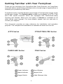
Getting Familiar with Your FuzzyScan
Thank you for choosing Cino FuzzyScan Bar Code Scanner. All FuzzyScan
scanners deliver world-class performance for a broad range of applications to
unleash your productivity with ease.
FuzzyScan family includes A series area imager, F series linear imager and L
series laser imager. The Antimicrobial models are available for A770, L780
and F780 series scanners which are equipped with Disinfectant-ready
Housing and Vibrator. More over, the option of Vibrator is available for all
other series upon request. For more details, please visit our web site or
contact your supplier.
This document provides an easy reference for installation and operation
purpose. The complete documentation is available at www.cino.com.tw.
A770 Series
F790/F780/L780 Series
F680/L680 Series
F560 Series
Power Indicator
Scan Window
Status Indicator
Beeper Hole
Trigger Switch
Cable Release Hole
1
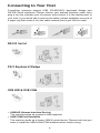
Connecting to Your Host
FuzzyScan scanners support USB, PS/2(DOS/V) Keyboard Wedge and
RS-232 Serial interfaces. Please choose your desired interface cable, then
plug it into the interface port of scanner and connect it to the desired port of
your host. If you would like to remove the cable, please straighten one end of
a paper clip then insert it into the cable release hole to pull out the cable.
RS232 Serial
PS/2 Keyboard Wedge
USB HID & USB COM
y USB HID (Human Interface Device)
The scanner works as a generic USB keyboard.
y USB COM Port Emulation
The scanner works as a legacy RS232 serial device. Please note that you
have to install the USB Virtual COM software driver before using.
2
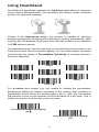
Using SmartStand
SmartStand is specifically designed for hand-free applications to maximize
user’s comfort and productivity. You can adjust the scanner holder to desired
position for optimized scanning.
Thanks to the Auto-sense design, the scanner is capable of switching
between presentation scanning and hand-held scanning automatically while
working with SmartStand. But please note that this function is not available
for F560 series scanners.
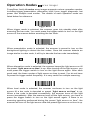
In presentation mode, the bar code may not be detected by the scanner in an
environment with very dim ambient lighting. You can select higher sensitivity
level through the setting of Presentation Sensitivity to increase scanner’s
detection sensitivity.
Level 3
Level 1
Level 6
Level 4
Level 2
Level 7
Level 5 ◆
For A series area imager, you can enable or disable the presentation
background lighting of scanner according to the ambient light condition in
presentation mode. When the ambient light is dim or dark, you can enable
this function to turn on the scanner’s LED illumination at a dim level. This is
helpful for scanner to detect the motion of scene.
Presentation Background Lighting
On ◆
Presentation Background Lighting
Off
3
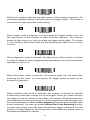
Operation Modes
area imager
FuzzyScan family A series array imager supports various operation modes,
including trigger, presentation, alternative, level, force, toggle, diagnostic, low
power and multiple read modes. The details of each operation mode are
listed below for reference.
Trigger Mode
When trigger mode is selected, the scanner goes into standby state after
scanning the bar code. You must press the trigger switch to turn on the light
source of the scanner before scanning the bar code.
Presentation Mode
When presentation mode is selected, the scanner is preset to turn on the
background lighting to detect the bar codes. Once the scanner detects an
image similar to a bar code, it will try to decode the bar code immediately.
Alternative Mode
When alternative mode is selected, the scanner keeps the light source on till
the preset “light source on time” is up. After turning off the light source, you
must press the trigger switch to turn on the light source again. After each
good read, the timer counter of light source on time is reset. You do not have
to press the trigger switch frequently. It is very useful for multiple scanning.
Level Mode
When level mode is selected, the scanner continues to turn on the light
source till a bar code is decoded or preset “light source on time” is up.
When a bar code is decoded successfully, the scanner turns off the light
source immediately. After the scanner turns off the light source, you have to
press the trigger switch to turn on the light source again. If there is no
scanning operation performed during the preset “light source on time”, the
scanner will turn off the light source after the preset light source on time is up.
4
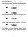
Force Mode
When force mode is selected, the light source of the scanner is forced on for
continued operation without having to press the trigger switch. This mode is
convenient for high speed bar code reading.
Toggle Mode
When toggle mode is selected, you must press the trigger switch to turn on
the light source of the scanner to start scanning operation. The scanner
keeps the light source on until you press the trigger switch again. This mode
is very similar to alternative mode but without the preset light source on time
concern.
Diagnostic Mode
When diagnostic mode is selected, the light source of the scanner is forced
on without regard for other programmable parameters, such as reread delay,
redundancy, and so on.
Low Power Mode
When low power mode is selected, the scanner goes into idle state after
scanning the bar code. You must press the trigger switch to wake up the
scanner for operation.
Multiple Read Mode
When multiple read mode is selected, the scanner is allowed to decode
multiple bar codes with a single pull of the trigger. When you press and hold
the trigger to aim at a series of bar codes, the scanner will decode each bar
code and beep for each good read. For more precise bar code decoding, you
are recommended to enable Center Alignment function while multiple read
mode is selected. You also can enable Unique Bar Code Reporting function
to report only unique bar code when the scanner trigger is pressed. For the
setting of Center Alignmen and Unique Bar Code Reporing, please refer to
Programming Manual for details.
5
Operation Modes
linear & laser imager
Both F series linear imager and L series laser imager of FuzzyScan family
support various operation modes, including trigger, presentation, alternative,
level, flash, force, toggle, diagnostic and low power modes. But please note
that the laser aiming line of L series is not performed under force, flash,
toggle or diagnostic mode to ensure the longer working life of laser imager.
Trigger Mode
When trigger mode is selected, the scanner goes into standby state after
scanning the bar code. You must press the trigger switch to turn on the light
source of the scanner before scanning the bar code.
Presentation Mode
When presentation mode is selected, the scanner will turn on the light source
and start scanning operation automatically if it detects an image similar to a
bar code. In case the scanner can’t detect a bar code, it will turn off the light
source when the preset light source on time is up.
Alternative Mode
When alternative mode is selected, the scanner keeps the light source on till
the preset “light source on time” is up. After turning off the light source, you
must press the trigger switch to turn on the light source again. After each
good read, the timer counter of light source on time is reset. You do not have
to press the trigger switch frequently. It is very useful for multiple scanning.
Level Mode
When level mode is selected, the scanner continues to turn on the light
source till a bar code is decoded or preset “light source on time” is up.
When a bar code is decoded successfully, the scanner turns off the light
source immediately. After the scanner turns off the light source, you must
press the trigger switch to turn on the light source again. If there is no
scanning operation performed during the preset “light source on time”, the
scanner will turn off the light source after the preset light source on time is up.
6
Flash Mode
When flash mode is selected, the scanner flashes the light source without
having to press the trigger switch. If the scanner detects an image which is
similar to a bar code, it forces on the light source automatically and scans the
bar code.
Force Mode
When force mode is selected, the light source of the scanner is forced on for
continued operation without having to press the trigger switch. This mode is
convenient for high speed bar code reading.
Toggle Mode
When toggle mode is selected, you must press the trigger switch to turn on
the light source of the scanner to start scanning operation. The scanner
keeps the light source on until you press the trigger switch again. This mode
is very similar to alternative mode but without the preset light source on time
concern.
Diagnostic Mode
When diagnostic mode is selected, the light source of the scanner is forced
on without regard for other programmable parameters, such as reread delay,
redundancy, and so on.
Low Power Mode
When low power mode is selected, the scanner goes into idle state after
scanning the bar code. You must press the trigger switch to wake up the
scanner for operation.
7
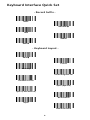
Keyboard Interface Quick Set
- Record Suffix -
None
RETURN ◆
TAB
SPACE
ENTER
- Keyboard Layout -
USA ◆
France
Germany
United Kingdom-UK
Canadian French
Spain (Spanish)
Spain (Latin America)
Nertherlands
Japan
Sweden/Finland
8
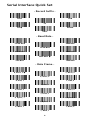
Serial Interface Quick Set
- Record Suffix -
None
TAB
LF
CR ◆
SPACE
CRLF
- Baud Rate –
115.2K BPS
4800 BPS
19.2K BPS
57.6K BPS
2400 BPS
9600 BPS ◆
38.4 BPS
1200 BPS
- Data Frame -
8, None, 1 ◆
7, None, 2
8, None, 2
8, Odd, 1
7, Odd, 2
7, Odd, 1
8, Even, 1
7, Even, 2
7, Even, 1
8, Space, 1
7, Space, 2
7, Space, 1
8, Mark, 1
7, Mark, 2
7, Mark, 1
9
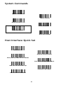
System Commands
System Information
Master Default
PowerTool Host Link
User Default
Factory Default
Save User Default
Host Interface Quick Set
RS232 Serial
Keyboard Replacement
PS/2 (DOS/V) KBW Standard Mode
PS/2 (DOS/V) KBW Turbo Mode
USB HID Standard Mode ◆
USB HID Turbo Mode
USB Com Port Emulation
10
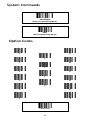
System Commands
PROGRAM
(Enter Programming Mode)
END
(Exit Programming Mode)
Option Codes
0
A
6
1
B
7
2
C
8
3
D
9
4
E
5
F
FIN (Finish)
11
Keyboard Interface Control
Command
Keyboard Layout
Record Suffix
Parameter Selection
Option Code
USA ◆
France
Germany
United Kingdom-UK
Canadian French
Spain
Sweden/Finland
Portugal
Norway
Latin America
Italy
Netherlands
Denmark
Belgium
Switzerland-Germany
Iceland
Japan
Czech
00
01
02
03
04
05
06
07
08
09
10
11
12
13
14
15
16
17
None
RETURN ◆
TAB
SPACE
ENTER
User define character
0
1
2
3
4
5
Preamble
None ◆
1-15 characters
FIN
[00-7F], [FIN]
Postamble
None ◆
1-15 characters
FIN
[00-7F], [FIN]
Intermessage Delay
None ◆
1-99 (x5) msec.
FIN
(2 digits)
Intercharacter Delay
None ◆
1-99 (x5) msec.
FIN
(2 digits)
Interfunction Delay
None ◆
1-99 (x5) msec.
FIN
(2 digits)
Caps Lock Control
“Caps Lock Off’’ State ◆
“Caps Lock On’’ State
Auto Detect
0
1
2
“Caps Lock On, Caps Off” ◆
“Caps Lock On, Shift Off”
0
1
Enable ASCII 00-31 as KB function code output ◆
Enable ASCII 00-31 as Ctrl-xx output
0
1
Key Pad Emulation
Disable key pad emulation ◆
Enable numeric output as key pad output
0
1
Upper/Lower Case
Normal case ◆
Inverse case
Upper case
Lower case
0
1
2
3
Caps Lock Release Control
Function Key Emulation
12
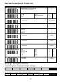
Serial Interface Control
Command
Parameter Selection
STX/ETX Control
Option Code
Disable STX/ETX transmission ◆
Enable STX/ETX transmission
Record Suffix
None
CR ◆
LF
CRLF
0
1
TAB
SPACE
User define character
0
1
2
3
4
5
6
Preamble
None ◆
1-15 characters
FIN
[00-7F], [FIN]
Postamble
None ◆
1-15 characters
FIN
[00-7F], [FIN]
Handshaking Protocol
None ◆
RTS/CTS
ACK/ NAK
Xon/Xoff
0
1
2
3
Intermessage Delay
None ◆
1-99 (x5) msec.
FIN
(2 digits)
Intercharacter Delay
None ◆
1-99 (x5) msec.
FIN
(2 digits)
Interfunction Delay
None ◆
1-99 (x5) msec.
FIN
(2 digits)
Serial Response Time-out
None
200 msec.
500 msec. ◆
800 msec.
1 sec.
2 sec.
NAK Retry Count
3 times ◆ 0~255 times
0
1
2
3
4
5
3 sec.
4 sec.
5 sec.
8 sec.
10 sec.
15 sec.
6
7
8
9
A
B
FIN
(3 digits)
Message String Breakdown
Keyboard interface output (PS/2, DOS/V, USB HID)
Preamble
Data Length
Prefix ID
Scanned Data
Suffix ID
Postamble
Record Suffix
1-15 char.
2-4 digits
1 or 3 char.
Variable
1 or 3 char.
1-15 char.
1 char.
Serial interface output (RS-232, USB COM Port Emulation)
STX
1 char.
Preamble Data Length
1-15 char.
2-4 digits
Prefix ID
1 or 3 char.
Scanned Data Suffix ID
Variable
13
Postamble
1 or 3 char. 1-15 char.
ETX
Record Suffix
1 char.
1 char.
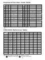
Keyboard Function Code Table
No. ANSI ASCII
No. ANSI ASCII
Key Function
Ctrl Output
Key Function
Ctrl Output
00
NUL
00H
RESERVED
Ctrl + @
16
DLE
10H
F7
Ctrl + P
01
SOH
01H
CTRL (Left)
Ctrl + A
17
DC1
11H
F8
Ctrl + Q
02
STX
02H
ALT (Left)
Ctrl + B
18
DC2
12H
F9
Ctrl + R
03
ETX
03H
SHIFT
Ctrl + C
19
DC3
13H
F10
Ctrl + S
04
EOT
04H
CAPS LOCK
Ctrl + D
20
DC4
14H
F11
Ctrl + T
05
ENQ
05H
NUM LOCK
Ctrl + E
21
NAK
15H
F12
Ctrl + U
06
ACK
06H
ESC
Ctrl + F
22
SYN
16H
INS (Insert) (Edit)
Ctrl + V
07
BEL
07H
F1
Ctrl + G
23
ETB
17H
DEL (Delete) (Edit)
Ctrl + W
08
BS
08H
BACK SPACE
Ctrl + H
24
CAN
18H
HOME (Edit)
Ctrl + X
09
HT
09H
TAB
Ctrl + I
25
EM
19H
END (Edit)
Ctrl + Y
10
LF
0AH
F2
Ctrl + J
26
SUB
1AH
PAGE UP (Edit)
Ctrl + Z
11
VT
0BH
F3
Ctrl + K
27
ESC
1BH PAGE DOWN (Edit)
12
FF
0CH
F4
Ctrl + L
28
FS
1CH
UP (Edit)
13
CR
0DH
ENTER (CR)
Ctrl + M
29
GS
1DH
DOWN (Edit)
Ctrl + ]
14
SO
0EH
F5
Ctrl + N
30
RS
1EH
LEFT (Edit)
Ctrl + 6
15
SI
0FH
F6
Ctrl + O
31
US
1FH
RIGHT (Edit)
* see note
Ctrl + [
Ctrl + \
The last character in the Ctrl Output column is varied for different countries.
HEX/ASCII Reference Table
H
0
1
2
3
4
5
6
7
0
NUL
DLE
SPACE
0
@
P
`
p
1
SOH
DC1
!
1
A
Q
a
q
2
STX
DC2
"
2
B
R
b
r
3
ETX
DC3
#
3
C
S
c
s
L
4
EOT
DC4
$
4
D
T
d
t
5
ENQ
NAK
%
5
E
U
e
u
6
ACK
SYN
&
6
F
V
f
v
7
BEL
ETB
'
7
G
W
g
w
8
BS
CAN
(
8
H
X
h
x
9
HT
EM
)
9
I
Y
i
y
A
LF
SUB
*
:
J
Z
j
z
{
B
VT
ESC
+
;
K
[
k
C
FF
FS
,
<
L
\
l
|
D
CR
GS
-
=
M
]
m
}
E
SO
RS
.
>
N
^
n
~
F
SI
US
/
?
O
_
o
DEL
Example: ASCII “A”→ HEX “41” ; ASCII “a”→ “61”
: High Byte of HEX Value
: Low Byte of HEX Value
14
www.cino.com.tw
FuzzyScan Barcode Scanner Quick Start Guide
International Edition, Rev. C1
P/N: YMAUB00010040R0
Disclaimer
Cino makes no warranty of any kind with regard to this publication, including, but not limited to, the
implied warranty of merchantability and fitness for any particular purpose. Cino shall not be liable for
errors contained herein or for incidental consequential damages in connection with the furnishing,
performance, or use of this publication. This publication contains proprietary information that is protected
by copyright. All rights are reserved. No part of this publication may be photocopied, reproduced or
translated into any language, in any forms, in an electronic retrieval system or otherwise, without prior
written permission of Cino. All product information and specifications shown in this document may be
changed without prior notice.
© COPYRIGHT CINO GROUP • PC WORTH INT’L CO., LTD. ALL RIGHT RESERVED.
Warranty
Cino warrants its products against defects in workmanship and materials from the date of shipment,
provided that the product is operated under normal and proper conditions. The warranty provisions and
durations are furnished by different warranty programs. The above warranty does not apply to any
product which has been (i) misused; (ii) damaged by accident or negligence; (iii) modified or altered by the
purchaser or other party; (iv) repaired or tampered by unauthorized representatives; (v) operated or stored
beyond the specified operational and environmental parameters; (vi) applied software, accessories or
parts are not supplied by Cino; (vii) damaged by circumstances out of Cino’s control, such as, but not
limited to, lightning or fluctuation in electrical power. Any defective product must follow the warranty
program and RMA procedures to return Cino for inspection.
Regulatory
Part 15 Subpart B
CNS13438
EN55022, EN55024
EN61000-3-2, EN61000-3-3, EN60950-1
EN61000-6-3, EN61000-6-2
AS/NZS CISPR 22:2009 Class B
KN22, KN24 (KN61000-2,-3, -4,-5, -6,-8,-11)
V-3/2011.04, TECHNICAL REQUIREMENTS,
Class B ITE
LED Eye Safety
IEC62471 Exempt group
Laser Eye Safety
IEC60825-1 Class 1