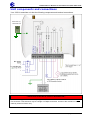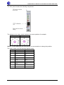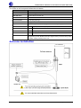
1
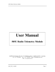
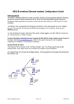
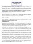
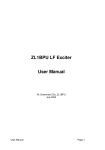
Quick Start Guide ELPRO 105U-L-T Wireless I/O Transmitter Unit man_105U-L-T_QuickStart_v1-8.doc ELPRO 105U-L-T Wireless I/O Transmitter Unit Quick Start Guide About this document This document is the ELPRO 105U-L-T Wireless I/O Transmitter Unit Quick Start Guide and contains the following sections: Section Read this section if you want to … Basic steps for using your unit Learn the basic steps for installing and using your unit. Factory default configuration Understand how the transmitter sends information to the receiver. Unit components Understand the different parts of your unit. Antenna installation Learn how to install an antenna with your unit. Resetting factory defaults Reset your unit to the original factory default settings. Linking transmitter and receiver units Link your units to work as a dedicated pair. Safety information Understand important safety information related to your unit. NOTE: You must read this information before installing your unit. Specifications Know technical information about your unit. For more information, see the next sections. Basic steps for using your unit This document describes how to configure your unit using the default factory configuration that lets you easily setup your network as a simple send/receive network using a dedicated pair of transmitter and receiver units. The basic steps for using your unit are: 1. Connect the antenna, power supply and transducer signals using the instructions in this document. Power supply and transducer connection is described in the section Unit components and connections. Antenna connection is described in the section Antenna installation. For more information, see the 105U-L Installation Manual. 2. Reset the transmitter and receiver units to the factory default configurations. 3. Link the transmitter and receiver units to work as a dedicated pair. 4. Bench test your configuration before deploying. NOTE: You can also configure your network using a user-defined customised configuration that lets you set specific information about your network. For more information on setting a userdefined customised configuration, see the 105U-L User Manual on the enclosed CD. Factory default configuration When you configure the units using the configuration in this document, the inputs from the transmitter are sent to the outputs at the receiver as follows: 105U-L-T(Transmitter) Sends 105U-L-R (Receiver) Digital Input 1 Digital Output 1 Digital Input 2 Digital Output 2 Analogue Setpoint Digital Output 3 Analogue input (4-20 mA) Analog output Thermocouple Input (Not used) Communication Failure (Comes on if no messages from 105U-LT) Setpoint Output (Local indication) System OK (On if system OK) ELPRO 105U-L-T Wireless I/O Transmitter Unit System OK (On if system OK) Version 1.8 page 2 of 8 ELPRO 105U-L-T Wireless I/O Transmitter Unit Quick Start Guide Unit components and connections Your 105U-L transmitter unit has the following components and terminal connections: Earth Wire Lug underneath Unit **IMPORTANT ELECTRICAL SAFETY INFORMATION** In order to comply with Electrical Safety Regulations, this module must be installed in an Electrical AND Fire enclosure. This enclosure may be a single or multiple enclosures. Access to the module is to be made by a Service Person only. ELPRO 105U-L-T Wireless I/O Transmitter Unit Version 1.8 page 3 of 8 ELPRO 105U-L-T Wireless I/O Transmitter Unit Quick Start Guide The front panel contains the following components: The triangle on the rotary switch indicates the current position, for example: Position 0 Position 1 NOTE: To avoid damaging the rotary switch, use a screwdriver to change the position. The rotary switch uses the following setpoint levels: Position Lower level (mA) Upper level (mA) 1 4.8 6.4 2 6.4 8.0 3 8.0 9.6 4 9.6 11.2 5 11.2 12.8 6 12.8 14.4 7 14.4 16.0 8 16.0 17.6 9 17.6 19.2 ELPRO 105U-L-T Wireless I/O Transmitter Unit Version 1.8 page 4 of 8 ELPRO 105U-L-T Wireless I/O Transmitter Unit Quick Start Guide The LEDs on the front panel indicate the unit status: LED Status Indicates None No power supply. OK LED Green Current status of the unit OK. OK LED Red Fault condition detected in unit. TX Led Flashes Transmitting Message. PG LED on Configuration Cable Connected. Input LED ON Input LEDS (i.e. D1,D2, SP, AZ.) light when the corresponding input is active. All LEDs medium flash D1 Digital Input 1 is active (Low). D2 Digital Input 2 is active. SP Analog Setpoint is active. AZ Analog Input is zero mA Medium speed flash (1.6HZ) indicates the module is half-way through the configuration process. Medium flash also happens when you set the rotary switch to position 0 when powering on the unit. Antenna installation ELPRO 105U-L-T Wireless I/O Transmitter Unit Version 1.8 page 5 of 8 ELPRO 105U-L-T Wireless I/O Transmitter Unit Quick Start Guide Resetting your unit to factory defaults To reset the default factory configuration: 1. Set the RSSI rotary switch to position 0 using a screwdriver. 2. Power on the 105U-L transmitter. 3. The 105U-L transmitter flashes all LEDs at medium flash (i.e. 1.6 Hz). NOTE: If the LEDs do not flash, you must repeat steps 1 and 2 until the LEDs flash before continuing. 4. Set the RSSI rotary switch to another position (i.e. position 1) within 5 seconds. 5. Set the RSSI rotary switch to position 0 within another 5 seconds. 6. The 105U-L transmitter lights all LEDs for 2 seconds before returning to normal operation. NOTE: If the LEDs do not light for 2 seconds, you must repeat the process from step 1 until the LEDs light before continuing. 7. You can now link the transmitter and receiver units. Linking your transmitter and receiver units You must reset the transmitter unit to factory defaults (to disable encryption) before linking the transmitter and receiver units. For more information, see the previous section. NOTE: You must complete the linking process in 60 seconds. To link the transmitter and receiver units: 1. Press and hold down the RSSI Pushbutton on the receiver. 2. Power on the receiver while holding down the RSSI Pushbutton 3. Release the RSSI Pushbutton as soon as the Receiver LEDS flash (within 5 seconds of powering the receiver). 4. The receiver will flash all LEDs for a maximum 60 seconds while it tries to link to the transmitter. 5. Power on the transmitter. The transmitter sends a special “Link” message to allow the receiver to recognise the transmitter. 6. When the units link, the receiver lights all LEDs for 2 seconds before returning to normal operation. NOTE: If the receiver LEDs continue flashing within the 60 seconds, the units are not linked and you should retry the linking process by powering the transmitter off and on again. If you exceed the 60 seconds, you must restart the linking process from step 1. 7. You can now bench test your configuration before deploying. ELPRO 105U-L-T Wireless I/O Transmitter Unit Version 1.8 page 6 of 8 ELPRO 105U-L-T Wireless I/O Transmitter Unit Quick Start Guide Safety information Thank you for selecting the 105U-L transmitter for your telemetry needs. We trust it will give you many years of valuable service. To ensure your 105U-L transmitter enjoys a long life, double-check ALL your connections with the user’s manual before powering on the unit. WARNING: Incorrect termination of supply wires may cause internal damage and will void warranty. Unit specifications Input/output Number Additional information Digital inputs 2 Analog inputs 1 Thermocouple inputs 1 Power supply 1 Transmitter 1 Dry-contact digital inputs slow-pulsed at 10Hz. All inputs are suitable for voltage free contacts (e.g. mechanical switches) or NPN transistor devices (e.g. electronic proximity switches). NOTE: PNP transistor device inputs are NOT suitable. 0-20mA differential input; 16-bit resolution, 0.1% accuracy, 10 ohm input impedance. J, K or T type thermocouple with on-board cold-junction compensation. Cold junction compensation accuracy ±1º over ambient temp range: -40º to +70ºC. 9-30 VDC 1 Amp CSA certified Class 2 power supply. For use in Class I Div 2 explosive areas, the power supply must be approved for Class I Div 2 use. WARNING: Explosion hazard - do not disconnect while circuit is live unless area is known to be non-hazardous. 5 mW or 500 mW DFSK Fixed Frequency Transmitter. Frequency 868.525 MHz 500 mW - 5km out of plant, 1km obstructed environment. 869.875MHz 5 mW – 1km out of plant. 300m obstructed environment ELPRO 105U-L-T Wireless I/O Transmitter Unit Version 1.8 page 7 of 8 ELPRO 105U-L-T Wireless I/O Transmitter Unit Quick Start Guide Document information Quick Start Guide ELPRO 105U-L-T Wireless I/O Transmitter Unit Version 1.8 ELPRO contact details Address > 9 /12 Billabong Street Stafford, QLD 4053 Telephone > + 61 (0)7 3352 4533 Fax > + 61 (0)7 3352 4577 Email > [email protected] Website > www.elprotech.com Copyright Copyright © 2006 ELPRO Technologies Pty Ltd. All rights reserved. Limited lifetime warranty, disclaimer and limitation of remedies ELPRO products are warranted to be free from manufacturing defects for the “serviceable lifetime” of the product. The “serviceable lifetime” is limited to the availability of electronic components. If the serviceable life is reached in less than three years following the original purchase from ELPRO, ELPRO will replace the product with an equivalent product if an equivalent product is available. This warranty does not extend to: - Failures caused by the operation of the equipment outside the particular product's specification, or - Use of the module not in accordance with this User Manual, or - Abuse, misuse, neglect or damage by external causes, or - Repairs, alterations, or modifications undertaken other than by an authorized Service Agent. ELPRO’s liability under this warranty is limited to the replacement or repair of the product. This warranty is in lieu of and exclusive of all other warranties. This warranty does not indemnify the purchaser of products for any consequential claim for damages or loss of operations or profits and ELPRO is not liable for any consequential damages or loss of operations or profits resulting from the use of these products. ELPRO is not liable for damages, losses, costs, injury or harm incurred as a consequence of any representations, warranties or conditions made by ELPRO or its representatives or by any other party, except as expressed solely in this document. ELPRO 105U-L-T Wireless I/O Transmitter Unit Version 1.8 page 8 of 8