1
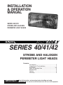
INSTALLATION
& OPERATION
MANUAL
SERIES 40/41/42
STROBE AND HALOGEN
PERIMETER LIGHT HEADS
SERIES 40/41/42
STROBE AND HALOGEN
PERIMETER LIGHT HEADS
Contents:
Introduction ......................................................... 2
Unpacking & Pre-Installation .............................. 2
Installation ........................................................ 3-4
Parts & Exploded View ....................................... 5
Maintenance ....................................................... 6
Options ............................................................... 6
Warranty ............................................................. 8
IMPORTANT:
Read all instructions and warnings before installing and using.
INSTALLER: This manual must be delivered to the end user of this equipment.
Introduction
The 40/41/42 Series Perimeter Light Heads are designed for the emergency vehicle market. The light heads are
to be connected to the Code 3® 475, 460, 235, or 440 Strobe Power Supplies (Strobe Model 40) or +12 VDC
output electromechanical or solid state flasher units (Halogen Models 41, 42), with the optional cable assemblies. These light heads with unique faceted shape are designed for optimum lighting at all angles. The Strobe
Model 40 meets and exceeds the SAE J1318 and California Title XIII output requirements for directional gaseous discharge lamps. The Halogen Model 42 with the 65W Transverse filament lamp assembly (S95285) exceeds the requirements of KKK-A-1822E.
Consisting of a lens, lamp assembly, reflector assembly, optional bezel and mounting fasteners, the Series 40,
41 and 42 Light Heads are easy to install. The design allows for interchangeability between the 40 Series Strobe
Light Heads and the 41/42 Series Halogen Light Heads giving the user freedom to customize the vehicle’s
lighting system.
!
WARNING!
The use of this or any warning device does not insure that all drivers can or will observe or react
to an emergency warning signal. Never take the right-of-way for granted. It is your
responsibility to be sure you can proceed safely before entering an intersection, driving against
traffic, responding at a high rate of speed, or walking on or around traffic lanes.
The effectiveness of this warning device is highly dependent upon correct mounting and wiring.
Read and follow the manufacturer’s instructions before installing or using this device. The
vehicle operator should insure daily that all features of the device operate correctly. In use, the
vehicle operator should insure the projection of the warning signal is not blocked by vehicle
components (i.e.: open trunks or compartment doors), people, vehicles, or other obstructions.
This equipment is intended for use by authorized personnel only. It is the user’s responsibility
to understand and obey all laws regarding emergency warning devices. The user should check
all applicable city, state and federal laws and regulations.
Public Safety Equipment, Inc., assumes no liability for any loss resulting from the use of this
warning device.
Proper installation is vital to the performance of this warning device and the safe operation of
the emergency vehicle. It is important to recognize that the operator of the emergency vehicle
is under psychological and physiological stress caused by the emergency situation. The
warning device should be installed in such a manner as to: A) Not reduce the output
performance of the system, B) Place the controls within convenient reach of the operator so
that he can operate the system without losing eye contact with the roadway.
Emergency warning devices often require high electrical voltages and/or currents. Properly
protect and use caution around live electrical connections. Grounding or shorting of electrical
connections can cause high current arcing, which can cause personal injury and/or severe
vehicle damage, including fire. Do not touch the strobe light tubes, the strobe light head
assemblies or the strobe power supply while the system is in operation. Wait 10 minutes after
turning off the power from system before touching any internal components. Always wear hand
and eye protection when handling strobe or halogen lamps. The lamps are pressurized and
breakage could result in injury from flying gas.
PROPER INSTALLATION COMBINED WITH OPERATOR TRAINING IN THE PROPER USE
OF EMERGENCY WARNING DEVICES IS ESSENTIAL TO INSURE THE SAFETY OF
EMERGENCY PERSONNEL AND THE PUBLIC.
Unpacking And Pre-Installation
Carefully remove the light head from its protective packaging. Inspect the unit for transit damage (broken lamp
assembly, etc). Report any damage to the carrier and keep the shipping carton. Verify that four #6 x 1-1/2”
screws per lighthead are included. The optional three wire cable comes in a 15, 20 or 25 foot length. Both ends
have Amp #60619-1 sockets attached to each wire. The cable comes with a parts bag consisting of 2 AMP #1480303-0 Mate-N-Lock socket housings and 1 #8 noninsulated ring terminal. Verify that these items are also
included.
2
Installation
2.000 MINIMUM
INTERIOR WALL OF VEHICLE OR
NEAREST OBSTACLE DIRECTLY BEHIND
LIGHT HEAD
EXTERIOR WALL OF VEHICLE
FIGURE 1
!
WARNING!
FIGURE 2
SHIELD WIRE
(CUT FLUSH)
RED WIRE - HIGH VOLTAGE
BLACK WIRE - GROUND (EARTH)
WHITE WIRE - TRIGGER
FIGURE 3
3
This is a full size template.
Do not use a facsimile or
copied reproduction. Do
not use this template if the
largest dimension in each
direction is not within +/-.010.
1.
Select the desired mounting location for the strobe light head assembly.
2.
Verify 2 inches minimum free clearance behind the mounting surface, see Figure 1.
3.
Cut the opening and drill the holes, use Figure 2 template or the trim bezel if your light head is so equipped.
4.
With one end of the cable at the light head mounting location, route the three wire cable to the Power
Supply.
5.
At the light head end of the cable, insert the 3 AMP sockets into the AMP socket housing as shown in
Figure 3. Cut the shield wire flush with the jacket. (Strobe Lamp Assembly shown. Procedure is the same
for Halogen Lamp Assembly.)
6.
Allow 3 inches minimum slack at the light head to facilitate lamp assembly replacement. Secure the cable.
7.
At the power source end of the cable determine if the cable length is acceptable. If a shorter length is
required, coil the cable and tie with an electrical tie.
8.
Insert the 3 AMP sockets into the AMP socket housing as shown in Figure 4.
9.
Crimp the #8 ring terminal to the shield wire and attach to nearest grounded structure. (Strobe Model 40
Only.)
WHITE WIRE - TRIGGER(Model 40 only)
BLACK WIRE - GROUND (EARTH)
RED WIRE - HIGH VOLTAGE
(STROBE)
12/24 VDC(HALOGEN)
THIS END TO POWER
SUPPLY
FIGURE 4
SHIELD WIRE (Model 40 Only)
For 40, 41 or 42 series models with optional bezel snap the reflector into the bezel making sure the
reflector's "TOP" aligns with the bezel's 7023 product number. To insure proper sealing between the
bezel and the mounting surface, align the supplied bezel gasket with the details in the back of the bezel.
10.
Test the lamp assembly (strobe or halogen) by connecting the reflector assembly to the cable and the
cable to the power source per the instructions with the power source.
11.
Push the assembled AMP Mate-N-Lock connectors through the cut out in the vehicle.
12.
Verify the '7021' product number on the reflector is on the top. Verify the "TOP" lens engraving is on the
top. Mount the reflector and lens by installing the four screws.
!
Light head must be mounted so that back side of reflector and bulb insertion area is enclosed
and shielded from weather.
WARNING!
4
Parts & Exploded Views
5
9
6
4
3
7
8
FIGURE 5
2
1
Parts List
Ref No.
Description
Part No.
1
Lens
T02270
T02271
T02272
T02273
T02274
T02275
2
Filter Half
(2 shown)
T02282 (Red)
T02283 (Blue)
T02284 (Amber)
3
Reflector
T07021
4
Gasket
T05328
5
Lamp Assembly
6
Trim Bezel
7
#6 Sheet Metal Screw, 1.75 long
8
Rope Gasket
T07005
9
Bezel Gasket
T03884
(Strobe)
(Halogen)
(Green)
(Clear)
(Red)
(Blue)
(Amber)
(Din Blue)
T07008
S82110(12v 50w red dot)
S95285(12v 65w
Transverse black dot-For
KKK-A-1822E Model 42
only)
S85347(24v 50w upgrade
purple dot)
S82120(12v 35w blue dot)
T07023
T07028
5
Maintenance
Lamp Assembly Replacement
!
High voltages and /or temperatures are present inside the unit. Disconnect from power and
wait 10 minutes prior to servicing or troubleshooting. Use hand and eye protection when
changing halogen lamps or flashtubes as they are pressurized and accidental breakage can
result in flying glass. Lamps are extremely hot! Allow to cool completely before attempting to
remove. Gloves and eye protection should be worn handling halogen lamps or flashtubes as
they are pressurized and accidental breakage can result in flying glass.
WARNING!
1.
2.
3.
4.
5.
6.
7.
8.
Turn off power to the power supply and allow the lamp assembly to cool for 10 minutes.
Remove the lens by unscrewing the four mounting screws.
Carefully grasp the base of the lamp assembly and twist counterclockwise 1/8 turn. Pull straight out.
Disconnect the lamp assembly from the cable.
Insert the replacement lamp assembly into the reflector. Twist clockwise 1/8 turn until you feel the
locking features of the socket engage.
Test the lamp assembly by connecting the lamp assembly to the cable. Switch the power source on.
After verifying the tube is good, turn off the power source.
Push the assembled AMP Mate-N-Lock connectors through the cut out in the vehicle for the reflector.
Verify the "7021" product number on the reflector is on the top. Verify “TOP” lens engraving is on the top
of the lens. Mount the reflector and lens by installing the four screws.
Lens Cleaning
1.
2.
3.
4.
Remove the lens by unscrewing the four mounting screws.
Using plain water and a soft cloth, or Code 3 lens polish and a very soft paper towel or facial tissue
clean both surfaces of the lens.
Because plastic scratches easily, cleaning is recommended only when necessary (about every six
months).
Do not subject the lenses to car washes that use brushes, as these will scratch the lenses.
!
If attempting to clean the reflector, use only a mild glass cleaner and a very soft cloth. Do not
attempt to use any wax type products as these will burn onto the reflector and impair effectiveness.
WARNING!
Options
The 40/41/42 Series Strobe and Halogen Perimeter Lighting Product Group includes the following models:
Single Products
Strobe
40
40BZ
Strobe tube assembly, reflector and lens
choice of six lens colors: amber, blue, clear, din blue, green and red.
Clear lens can be specified with optional inserted half lenses. Available in amber, blue, and red.
Strobe tube assembly, bezel, reflector and lens
choice of six lens colors: amber, blue, clear, din blue, green and red.
Clear lens can be specified with optional inserted half lenses. Available in amber, blue, and red.
Halogen
41
41BZ
Halogen lamp assembly, reflector and lens choice of six lens colors: amber, blue, clear, din blue, green
and red. Clear lens can be specified with optional inserted half lenses. Available in amber, blue, and
red.
Halogen lamp assembly, bezel, reflector and lens choice of six lens colors: amber, blue, clear, din blue,
green and red. Clear lens can be specified with optional inserted half lenses. Available in amber, blue,
and red.
6
Scene Lighting
41-08
41-12
41-15
41-26
41Z08
41Z12
41Z15
41Z26
Halogen lamp assembly, reflector and clear lens with an eight degree scene light filter.
Halogen lamp assembly, reflector and clear lens with a twelve degree scene light filter.
Halogen lamp assembly, reflector and clear lens with a fifteen degree scene light filter.
Halogen lamp assembly, reflector and clear lens with a twenty-six degree scene light filter.
Halogen lamp assembly, reflector, bezel and clear lens with an eight degree scene light filter.
Halogen lamp assembly, reflector, bezel and clear lens with a twelve degree scene light filter.
Halogen lamp assembly, reflector, bezel and clear lens with a fifteen degree scene light filter.
Halogen lamp assembly, reflector, bezel and clear lens with a twenty-six degree scene light filter.
KKK-A-1822E
42
42BZ
Halogen lamp assembly (S95285, 65W Transverse), reflector and lens choice of three lens colors:
amber, clear and red.
Halogen lamp assembly (S95285, 65W Transverse), bezel, reflector and lens choice of three lens
colors: amber, clear and red.
Case Products
40K
Case of ten model 40 strobe light heads, all of the same color
40BZK Case of ten model 40 strobe light heads with bezels, all of the same color
41K
Case of ten model 41 halogen light heads, all of the same color
41BZK
Case of ten model 41 halogen light heads with bezels, all of the same color
41-08K
Case of ten model 41-08 halogen scene light modules.
41-12K
Case of ten model 41-12 halogen scene light modules.
41-15K
Case of ten model 41-15 halogen scene light modules.
41-26K
Case of ten model 41-26 halogen scene light modules.
41Z08K
Case of ten model 41Z08 halogen scene light modules with bezel.
41Z12K
Case of ten model 41Z12 halogen scene light modules with bezel.
41Z15K
Case of ten model 41Z15 halogen scene light modules with bezel.
41Z26K
Case of ten model 41Z26 halogen scene light modules with bezel.
41BZK
Case of ten model 41 halogen light heads with bezels, all of the same color
41-08K
Case of ten model 41-08 halogen scene light modules.
41-12K
Case of ten model 41-12 halogen scene light modules.
41-15K
Case of ten model 41-15 halogen scene light modules.
41-26K
Case of ten model 41-26 halogen scene light modules.
41Z08K
Case of ten model 41Z08 halogen scene light modules with bezel.
41Z12K
Case of ten model 41Z12 halogen scene light modules with bezel.
41Z15K
Case of ten model 41Z15 halogen scene light modules with bezel.
41Z26K
Case of ten model 41Z26 halogen light heads, all the same color.
42K
Case of ten model 42 KKK-A-1822E halogen light heads, all of the same color.
42BZK
Case of ten model 42 KKK-A-1822E halogen light heads with bezels, all of the same color.
Upgrades:
CA upgrade to 55 watt twist lock bulb from 50 watt for
41, 41BZ, 41K, 41BZK.
7
WARRANTY
This product was tested and found to be operational at the time of manufacture. Provided
this product is installed and operated in accordance with the manufacturer's recommendations,
Public Safety Equipment guarantees all strobe reflector assemblies and all other parts and
components, for a period of 1 year from the date of purchase or delivery, whichever is later.
Units demonstrated to be defective within the warranty period will be repaired or replaced at the
factory service center at no cost.
Use of a lamp or other electrical load of a wattage higher than installed or recommended
by the factory, or use of inappropriate or inadequate wiring or circuit protection causes this
warranty to become void. Failure or destruction of the product resulting from abuse or unusual
use and/or accidents is not covered by this warranty. Use of non-PSE components and
assemblies may cause damage to the system and/or personal injury, and voids all warranties
on PSE systems and components.
PSE shall in no way be liable for other damages including consequential, indirect or
special damages whether loss is due to negligence or breach of warranty.
PSE MAKES NO OTHER EXPRESS OR IMPLIED WARRANTY INCLUDING,
WITHOUT LIMITATION, WARRANTIES OF FITNESS OR MERCHANTABILITY, WITH
RESPECT TO THIS PRODUCT.
PRODUCT RETURNS
In order to provide you with faster service, if you are going to return a product for
repair or replacement*, please contact our factory to obtain a Return Goods Authorization
Number (RGA number) before you ship the product to Code 3, Inc. Write the RGA number
clearly on the package near the mailing label. Be sure you use sufficient packing materials
to avoid damage to the product being returned while in transit.
*Code 3, Inc. reserves the right to repair or replace product at its discretion. Code 3, Inc. assumes no responsibility or liability for expenses
incurred for the removal and/or reinstallation of products requiring service and/or repair.
NEED HELP? Call our Technical Assistance Hotline - (314) 996-2800
Code 3, Inc.
10986 N. Warson Road
St. Louis, Missouri 63114-2029—USA
www.code3pse.com
Code 3 is a registered trademark of Code 3, Inc. a subsidiary of Public Safety Equipment, Inc.
Revision 8, 01/2006 - Instruction Book Part No. T07696
©2002-6 Code 3, Inc. Printed in USA