1
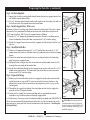
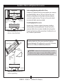
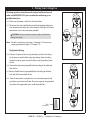
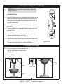
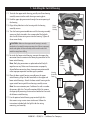
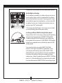
Tribeca Owner’s Guide and Installation Manual English Form# M6001-01 20140904 ©2014 Casablanca Fan Co. Welcome Your new Casablanca® ceiling fan is an addition to your home or office that will provide comfort and performance for many years. This installation and operation manual gives you complete instructions for installing and operating your fan. We are proud of our work. We appreciate the opportunity to supply you with the best ceiling fan available anywhere in the world. Before installing your fan, for your records and warranty assistance, record information from the carton and Casablanca nameplate label (located on the top of the fan motor housing). Cautions and Warnings Table Of Contents Preparing the Fan Site . . . . . . . . . . . . . . . . . . 3 1 • Getting Ready . . . . . . . . . . . . . . . . . . . . . . 6 2 • Installing the Ceiling Bracket . . . . . . . . 7 3 • Assembling and Hanging the Fan . . . . 8 4 • Wiring Your Ceiling Fan . . . . . . . . . . . . . 9 5 • Installing the Canopy . . . . . . . . . . . . . . . 10 6 • Assembling the Blades . . . . . . . . . . . . . . 11 7 • Installing the Switch Housing . . . . . . . . 12 8 • Operating and Cleaning Your Ceiling Fan . . . . . . . . . . . . . . . . . . . . . . . . . . . . . . . . 13 9 • Troubleshooting . . . . . . . . . . . . . . . . . . . . 14 • READ THIS ENTIRE MANUAL CAREFULLY BEFORE BEGINNING INSTALLATION. SAVE THESE INSTRUCTIONS. • Use only Casablanca replacement parts. • To reduce the risk of personal injury, attach the fan directly to the support structure of the building according to these instructions, and use only the hardware supplied. • To avoid possible electrical shock, before installing your fan, disconnect the power by turning off the circuit breakers to the outlet box and associated wall switch location. If you cannot lock the circuit breakers in the off position, securely fasten a prominent warning device, such as a tag, to the service panel. • All wiring must be in accordance with national and local electrical codes and ANSI/NFPA 70. If you are unfamiliar with wiring, use a qualified electrician. • To reduce the risk of personal injury, do not bend the blade attachment system when installing, balancing, or cleaning the fan. Never insert foreign objects between rotating fan blades. • To reduce the risk of fire, electrical shock, or motor damage, do not use a solid-state speed control with this fan. Use only Casablanca speed controls. • This product conforms to UL STD 507 and is certified to STD C22.2 No. 113. • Wash your hands after your fan installation is complete. © 2014 Casablanca Fan Company 2 M6001-01 • 09/04/14 • Casablanca Fan Company Preparing the Fan Site Step 1 - Choose the Fan Site Proper ceiling fan location and attachment to the building structure are essential for safety, reliable operation, maximum efficiency, and energy savings. Choose a fan site where: • No object can come in contact with the rotating fan blades during normal operation. • e fan blades are at least 7 feet above the floor and the ceiling is at least 9 feet high. • e fan blades have no obstructions to airflow, such as walls or posts, within 30 inches of the fan blade tips. • e fan is directly below a joist or support brace that will hold the outlet box and the full weight of the fan. 30” From Wall or Nearest Obstruction Checklist for Existing Fan Site 7’ Minimum Blades to Floor 9’ Minimum Ceiling Height Suitable Existing Fan Site If you want to use an existing fan site, complete the following checklist to determine if the site is acceptable and safe for your new Casablanca fan. If you cannot check off every item, prepare a new fan site as described on this page. Fan Support System • Fan attaches directly to building structure. • Fan support system will hold full weight of the fan and light kit. Ceiling Hole • e outlet box clearance hole is directly below the joist or support brace. Outlet Box • e outlet box is an UL-approved octagonal 4” x 1-1/2” outlet box (or as specified by the support brace manufacturer). • e outlet box is secured to the joist or support brace by wood screws and washers through the inner holes of outlet box. • e outer holes of the outlet box are aligned with joist or support brace. • e bottom of the outlet box is recessed a minimum of 1/16” into ceiling. Wiring • e electrical cable is secured to outlet box by an approved connector. • Six inches of lead wires extend from outlet box. If your existing fan site is suitable, skip ahead to Section 2 • Installing the Ceiling Bracket. Fan Support System Fan Support System Outlet Box Wiring 3 M6001-01 • 09/04/14 • Casablanca Fan Company Preparing the Fan Site (continued) Step 2 - Cut the Ceiling Hole 2-1. Locate the site for the ceiling hole directly below the joist or support brace that will hold the outlet box and fan. 2-2. Cut a 4” diameter hole through the drywall or plaster of the ceiling. You will use the hole to install the support brace and outlet box. Step 3 - Install a Support Brace, If Necessary Determine if there is a ceiling joist directly above the ceiling hole. If the joist is there, determine if it is positioned to allow you to recess the outlet box a minimum of 1/16” into the ceiling. If NOT, install a support brace as follows: 3-1. Attach a 2” x 4” support brace between two joists. Position it to allow you to recess the bottom of the outlet box a minimum of 1/16” into the ceiling. 3-2. Check the support brace to ensure it will support the full weight of the fan and light kit. Steps 2 – 3 Step 4 - Install the Outlet Box 4-1. Obtain a UL-approved octagonal 4” x 1-1/2” outlet box, plus two #8 x 1-1/2” wood screws and washers, available from any hardware store or electrical supply house. 4-2. Orient the outlet box so that both the inner and outer holes in the box align with the joist or support brace. 4-3. Drill pilot holes no larger than the minor diameter of the wood screws (5/64”) through the inner holes of the outlet box. 4-4. Attach the outlet box directly to the support brace or joist with two #8 x 1-1/2” Step 4 wood screws and washers. e bottom of the outlet box must be recessed a minimum of 1/16” into the ceiling. Step 5 - Prepare the Wiring 5-1. Make sure the circuit breakers to the fan supply line leads and associated wall switch location are turned off . If you cannot lock the circuit breakers in the off position, securely fasten a prominent warning device, such as a tag, to the service panel. 5-2. read the fan supply line through the outlet box so that the fan supply line extends at least 6” beyond the box. 5-3. Attach the fan supply line to the outlet box with an approved connector, available at any hardware store or electrical supply house. Step 5 5-4. Make certain the wiring meets all national and local standards and ANSI/NFPA 70. CAUTION: All wiring must be in You have now successfully prepared your ceiling fan site. For instructions to install accordance with national and local your ceiling fan, go to your fan manual and continue with Section 2 • Installing the electrical codes and ANSI/NFPA 70. If Ceiling Bracket. you are unfamiliar with wiring, use a qualified electrician. 4 M6001-01 • 09/04/14 • Casablanca Fan Company Installer’s Choice and Optional Accessories Understanding Mounting and Installer’s Choice Support Brace Standard Mounting Style Ceiling Outlet Box Considering Optional Accessories Consider using Casablanca’s optional accessories, including a wall-mounted or remote speed control. To install and use the accessories, follow the instructions included with each product. For quiet and optimum performance of your Casablanca fan, use only Casablanca speed controls. Standard Mounting hangs from the ceiling by a downrod (included). For ceilings higher than 9 feet, you can purchase Casablanca extension downrods. All Casablanca fans use sturdy 3/4” diameter pipe to assure stability and wobble-free performance. Support Brace Ceiling Outlet Box 8 Angled Mounting Style Casablanca’s 2-position mounting system provides you maximum installation flexibility and ease. You can install your fan in one of two ways, depending on ceiling height and your preference: standard or angled mounting. The steps in this manual include instructions for both mounting methods. CAUTION: To reduce the risk of personal injury, attach the fan directly to the support structure of the building according to these instructions, and use only the hardware supplied. 12 Angled Mounting recommended for a vaulted or angled ceiling. 5 M6001-01 • 09/04/14 • Casablanca Fan Company 1 • Getting Ready To install a ceiling fan, be sure you can do the following: • Locate the ceiling joist or other suitable support in ceiling. • Drill holes for and install wood screws. • Identify and connect electrical wires. • Lift 40 pounds. If you need help installing the fan, your Casablanca fan dealer can direct you to a licensed installer or electrician. Gathering the Tools You will need the following tools for installing the fan: • Electric drill with 9/64” bit • Standard screwdriver (magnetic tip recommended) • Phillips-head screwdriver (magnetic tip recommended) • Wrench or pliers • Ladder (height dependent upon installation site) Checking Your Fan Parts Carefully unpack your fan to avoid damage to the fan parts. Refer to the included Parts Guide. Check for any shipping damage to the motor or fan blades. If any parts are missing or damaged, contact your Casablanca dealer or call Casablanca Technical Support Department at 888-227-2178. Installing Multiple Fans? If you are installing more than one fan, keep the fan blades and blade irons (if applicable) in sets, as they were shipped. Preparing the Fan Site Before you begin installing the fan, follow all the instructions in “Preparing the Fan Site.” Proper ceiling fan location and attachment to the building structure are essential for safety, reliable operation, maximum efficiency, and energy savings. WARNING! To avoid possible electrical shock, make certain that electricity is turned off at the circuit breaker or fuse box before attempting any installation or repair procedure. 6 M6001-01 • 09/04/14 • Casablanca Fan Company 2 • Installing the Ceiling Bracket CAUTION: To avoid possible electrical shock, before installing your fan, disconnect the power by turning off the circuit breakers to the outlet box and associated wall switch location. If you cannot lock the circuit breakers in the off position, securely fasten a prominent warning device, such as a tag, to the service panel. Isolator Ceiling Bracket 2-1. Note: The ceiling bracket may be mounted to an existing ceiling-fan-rated outlet box. If the outlet box is not ceiling-fan-rated, Drill two pilot holes into the wood support structure. The pilot holes should be 9/64” in diameter and through the outermost holes in the outlet box. 2-2. Your fan comes with four neoprene noise isolators. Position the isolators between the ceiling bracket and the ceiling by inserting the raised areas on each isolator into the holes in the ceiling bracket. Step 2-2 2-3. Align the slotted holes in the ceiling bracket with the pilot holes you drilled in the wood support structure. Note: The isolators should be flush against the ceiling. 2-4. Place a flat washer on each of the two 3” wood screws and pass the screws through the slotted holes in the ceiling bracket into the pilot holes you drilled. Tighten the screws into the 9/64” pilot holes; do not use lubricants on the screws. Do not over tighten. Flat Washer 3” Wood Screw 7 M6001-01 • 09/04/14 • Casablanca Fan Company Steps 2-3 – 2-5 3 • Assembling and Hanging the Fan WARNING: Fan may fall if not assembled as directed in these installation instructions. Steps 3-1 – 3-4 Downrod You can assemble your fan for standard or angled mounting as shown in steps below. 3-1. Unbundle the wires from the fan. 3-2. Feed the wires from the fan through the downrod. Note: Make sure all the wires are on the same side of the metal dowel pin inside the downrod. 3-3. Loosen the square head setscrew on the adapter in order to install the downrod. 3-4. Insert the downrod into the adapter. Tighten by turning the downrod assembly at least 4-5 full turns until it stops. Note: When the downrod assembly is fully installed, 2-3 threads on the pipe will still be visible; this is normal. Securely retighten the setscrew with a wrench or pliers. Canopy Setscrew Adapter WARNING: If the setscrew is not tightened securely, the fan may fall. 3-5. (Optional) - The wires can be cut (shortened), but leave at least 8” extending from the top of the downrod. 3-6. Raise the fan and place the downrod ball into the ceiling bracket. For angled ceilings, point opening toward peak Step 3-6 Ceiling Bracket Downrod Ball 8 M6001-01 • 09/04/14 • Casablanca Fan Company 4 • Wiring Your Ceiling Fan All wiring must be in accordance with national and local electrical codes and ANSI/NFPA 70. If you are unfamiliar with wiring, use a qualified electrician. CEILING OM FR 4-1. Make sure the power is still off at the breaker box. green or bare (grounding) 4-2. To connect the wires, hold the bare metal leads together and place a wire connector over them, then twist clockwise until tight. For all wire connections use the wire connector provided. OM FAN FR green wire with yellow stripe green wire with yellow stripe CAUTION: Be sure no bare wire or wire strands are visible after making connections. Note: For dual switch wiring, skip steps 4-3 through 4-6. Continue on next page; performing steps 4-7 through 4-11. O CEIL ING BR Step 4-3 and 5-3 CEILING OM FR black (ungrounded) white (grounded) 4-6. After all connections are made, turn wire connectors upward and push them up into the outlet box. Be sure to separate the grounded wires from the ungrounded wires inside the outlet box. Steps 4-4 -4-5 black FRO blue white Wire Connector 9 M6001-01 • 09/04/14 • Casablanca Fan Company M KE FR 4-3. Connect the green or bare wire (grounding) wire from the ceiling to the green wire with yellow stripe (grounding) from the ceiling bracket and to the green wire with yellow stripe (grounding) from the fan. 4-4. Connect the white wire (grounded) from the ceiling to the white wire from the fan. 4-5. Connect the black wire (ungrounded) from the ceiling to the black wire and the blue wire from the fan. T Single Switch Wiring: M FA N AC 4 • Wiring Your Ceiling Fan (continued) CAUTION: Be sure no bare wire or wire strands are visible after making connections. CE OM ILING FR Dual Switch Wiring: black (ungrounded) black/white (ungrounded) white (grounded) black blue white 4-7. Connect the green or bare wire (grounding) from the ceiling to the green wire with yellow stripe (grounding) from the ceiling bracket to the green wire with yellow stripe (grounding) from the fan. See image on previous page. 4-8. Connect the white wire (grounded) from the ceiling to the white wire from the fan. 4-9. Connect the black wire (ungrounded) from the ceiling to the black wire from the fan. 4-10. Connect the blue wire from the fan to the black wire with white stripe (ungrounded) from the wall switch. 4-11. After all connections are made, turn wire connectors upward and push them up into the outlet box. Be sure to separate the grounded wires from the ungrounded wires inside the outlet box. FRO M FA N Steps 4-8 - 4-10 5 • Installing the Canopy 5-1. Raise the canopy over the ceiling bracket and align the two holes of the canopy and the ceiling bracket. 5-2. Insert and tighten the canopy screws securely. Hanger Bracket Canopy Screw Canopy Screw Canopy Step 5-1 Steps 5-2 10 M6001-01 • 09/04/14 • Casablanca Fan Company 6 • Assembling the Blades 6-1. Using the provided Allen wrench, attach each blade to the blade iron using three barrel nuts and three decorative screws as shown. Blade Iron Barrel Nut Note: You have the option to install the blade above or below the blade iron. In either instance, you may place the decorative screws and barrel nuts facing up or down. 6-2. Remove the two orange shipping rings from motor by lifting up on the edge of the rings. 6-3. Align the five holes in the blade iron ring and the decorative ring with the five holes in the bottom of the motor and partially install the five blade mounting screws. 6-4. Once all five of the screws are partially installed, tighten them securely. Decorative Screw Step 6-1 Allen Wrench Shipping Ring Blade Iron Ring Step 6-2 Note: The blades on this fan have been treated with Dust Armor protection, making the blades less likely to attract dust and dirt. Use a dry or slightly damp lint free cloth to clean the blades. Do not use a furniture polish or any other cleaners that leave any residue, as they will damage the protective Dust Armor on the blades. Decorative Ring Blade Mounting Screw Steps 6-3 - 6-4 11 M6001-01 • 09/04/14 • Casablanca Fan Company 7 • Installing the Switch Housing 7-1. To attach the upper switch housing, partially install two housing assembly screws into the switch housing mounting plate. 7-2. Feed the upper plug connector through the center opening of the housing. 7-3. Align the keyhole slots in the housing with the housing assembly screws. 7-4. Turn the housing counterclockwise until the housing assembly screws are firmly situated in the narrow end of the keyhole slots. Install the remaining screw into the housing. Tighten all three screws firmly. Upper Switch Housing Housing Assembly Screw Steps 7-1 – 7-4 CAUTION: Make sure the upper switch housing is securely attached to the switch housing mounting plate. Failure to properly attach and tighten all three assembly screws could result in the switch housing fixture falling. 7-5. To attach the lower switch housing, connect the upper plug connector from the motor to the lower plug connector in the lower switch housing. Note: Both plug connectors are polarized and will only fit together one way. Make sure the connectors are properly aligned before connecting them. Incorrect connection could cause improper operation and damage the product. Housing Assembly 7-6. Place the lower switch housing assembly over the upper Screw switch housing. Align the side screw holes in the upper and lower switch housings. Attach the lower switch housing to the upper switch housing with three housing assembly screws. Note: You can customize your Casablanca fan with a number of accessory light kits. To install an optional light kit, remove the logo cap by removing the two screws located on the inside of the lower switch housing. 7-7. Use the optional switch housing cap to attach light kits that mount using a center stem attachment. Follow the instructions included with the light kit for the wiring, mounting, and assembly. Lower Switch Housing Steps 7-5 – 7-6 Step 7-7 12 M6001-01 • 09/04/14 • Casablanca Fan Company 8 • Operating and Cleaning Your Ceiling Fan 8-1. Turn on electrical power to the fan. 8-2. The fan pull chain controls power to the fan. The pull chain has five settings in sequence: High, Medium, Low, Extra Low and Off. • Pull the chain slowly to change settings. • Release slowly to prevent the chain from recoiling into the blades. • The chain uses a breakaway connector that separates if the chain is jerked. If this happens, simply reinsert the chain into the connector. 8-3. The light pull chain controls the power to the light fixture. The chain has two settings: ON and OFF. 8-4. Ceiling fans work best by blowing air downward (counterclockwise In warm weather, use downward air flow pattern blade rotation) in warm weather to cool the room with a direct breeze. In winter, having the fan draw air upward (clockwise blade rotation) will distribute the warmer air trapped at the ceiling around the room without causing a draft. 8-5. For cleaning finishes, use a soft brush or lint-free cloth to prevent scratching. A vacuum cleaner brush nozzle can remove heavier dust. Remove surface smudges or accumulated dirt and dust using a mild detergent and a slightly dampened cloth. You may use an artistic agent, but never abrasive cleaning agents as they will damage the finish. 8-6. Clean wood finish blades with a furniture polishing cloth. Occasionally, apply a light coat of furniture polish for added protection and beauty. Clean painted and high-gloss blades in the same manner as the fan finish. To Change Airflow Direction Turn the fan off and let it come to a complete stop. Slide the reversing switch on the fan to the opposite position. Restart fan. Reversing Switch 13 M6001-01 • 09/04/14 • Casablanca Fan Company In cold weather, use upward air flow pattern 9 • Troubleshooting Problem: Nothing happens; fan does not move. 1.Turn power on, replace fuse, or reset breaker. 2.Loosen canopy, check all connections according to the wiring the fan section. 3.Remove the shipping bumpers. Problem: Noisy operation. 1.Tighten the blade assembly screws and blade iron armature screws until snug. 2.Check to see if the blade is cracked. If so, replace all the blades. Problem: Excessive wobbling. 1.If your fan wobbles when operating, use the enclosed balancing kit and instructions to balance the fan. 2.Tighten all blade iron screws. 3.Turn power off, support fan very carefully, and check that the hanger ball is properly seated. If you need parts or service assistance, please call 1-888-227-2178 or visit us at our website at http://www.CasablancaFanCo.com. Casablanca Fan Company 7130 Goodlett Farms Pkwy. #400 Memphis, Tennessee 38016 AUTHORIZED SERVICE CENTERS For the most updated listing of Casablanca Authorized Service Centers, visit www.CasablancaFanCo.com/servicecenters or call toll free 1-888-227-2178. 14 M6001-01 • 09/04/14 • Casablanca Fan Company Casablanca fans have the power to cut your cooling costs up to 40%. Beat the High Cost of Cooling The air movement created by a Casablanca ceiling fan lets you set your thermostat higher and still stay comfortable. Every degree you raise the thermostat saves up to 7% on energy costs. So, you can cut back on expensive air conditioning ... and save up to 40%* on cooling. In winter, your Casablanca fan recirculates warm air and saves up to 10%* on heating bills. * On average at low speed settings. Your savings may vary based on climate, building type and thermostat setting. Save Energy and Money While Protecting the Environment Congratulations! You’re saving energy and money while protecting the environment by purchasing this ENERGY STAR qualified Casablanca ceiling fan! With this purchase, you are doing your part to protect the environment. In 2010, ENERGY STAR qualified ceiling fans are projected to cut air pollution by more than 500 million pounds! Your new ceiling fan has earned the ENERGY STAR label because it meets high energy efficiency specifications set by the Environmental Protection Agency (EPA). ENERGY STAR labeled ceiling fans save energy because they have more efficient fan motors and air delivery due to more aerodynamic blade configurations. Ceiling fan models bearing the ENERGY STAR label move air 14 - 20% more efficiently than typical ceiling fan models. For more information on ENERGY STAR visit www.energystar.gov. 15 M6001-01 • 08/22/14 • Casablanca Fan Company