1
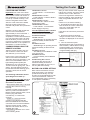
N A T U R A L L Y C O O L E R
Installation and Operating Manual
EXV Series
Evaporative Air Coolers
1
Index
INDEX
SAFETY.........................................................................................................1
OPERATING INSTRUCTIONS
Thermostat Range.........................................................................................2
Using the SENSORTOUCH Remote Control...................................................3
Using the SENSORTOUCH Wall Control.........................................................7
Maintenance.................................................................................................. 9
Pre-Assembly Inspection............................................................................... 10
INSTALLATION INSTRUCTIONS
Installation Details..........................................................................................11
Water Installation........................................................................................... 12
Electrical Installation...................................................................................... 13
SENSORTOUCH Wall Control........................................................................13
SENSORTOUCH Remote Control...................................................................14
Testing the cooler...........................................................................................16
Installation Checklist...................................................................................... 18
TROUBLE SHOOTING .................................................................................19
APPENDIX A - Wiring Diagrams.....................................................................21
1
Safety
SAFETY INSTRUCTIONS
Important Safety Instructions and
Warnings
WARNING: The warnings and safety
instructions in this manual must be
followed to reduce the risk of fire,
electric shock or injury, and to provide
reasonable safety and efficiency in
using this Evaporative Air Cooler. The
operator is responsible for following
the warnings and instructions in this
manual and on the cooler.
Read this entire manual before
proceeding to install the cooler.
Restrict the use of this cooler to
persons who read, understand and
can follow the warnings and
instructions in this manual and on
the cooler. NEVER ALLOW
CHILDREN TO OPERATE THE
COOLER.
Failure to observe these warnings
and instructions will void
manufacturer's warranties and will
discharge the manufacturer of all
liability.
CAUTION!
ALWAYS disconnect the cooler
from the power supply before
commencing maintenance
procedures.
During maintenance procedures,
NEVER use a naked flame for any
inspection or cleaning purpose as a
fire could be caused by a flame
coming into contact with the cooler
materials.
Avoid Dangerous Situations:
Protect the cooler from all sources
of ignition because polymers and
cooling pads will burn.
NEVER use a water hose to squirt
the interior of the cooler for cleaning
as residual water could damage
electrical components and create the
risk of fire and /or electric shock to
the user after re-assembly.
INSTALLATION, REPAIR AND
OPERATION
! All installation and repair work
must conform to local electrical, water
supply and environmental codes,
rules and regulations and applicable
national standards.
! All installation, maintenance and
repair work must be done by a
licensed and qualified electrician
and/or a qualified, experienced
heating, ventilating, air
conditioning technician. All such
work must be effected with factory
authorized spare parts only.
! Disconnect electrical power at the
fuse or circuit breaker box before
installation commences. ALWAYS
turn OFF the isolating switch
(disconnect) located on the electronic
module inside the cooler BEFORE
commencing any maintenance
! Use only the power supply voltage
shown on the motor/cabinet
nameplate.
! Do not install or service the air
cooler during rain, high wind or severe
weather conditions.
! Keep children, bystanders and
animals at a safe distance, a minimum
of 30ft (10m) away from working
areas.
! Dress safely. Wear non-skid shoes
when working at high levels and roofs.
Do not wear loose clothing or personal
accessories while installing or
servicing the air cooler as they may
become caught in moving parts.
! Keep loose hair, loose clothing,
fingers and all other parts of the body
away from openings and moving
parts.
! Check the cooler for worn, loose,
missing, or damaged parts before
operation.
! If you work with power tools, wear
protective eyewear and gloves.
! Take care when lifting or raising the
air cooler to its final location. Use safe
equipment and never attempt to lift the
cooler alone. Always have assistance.
Otherwise you might damage the
cooler or the building or injure
yourself.
! Ground Fault Circuit Interrupter
(GFCI) protection should be provided
on the circuit supplying this air cooler.
Receptacles are available with built-in
GFCI protection.
! Air coolers installed on roofs must
not have the waste water directed
onto the roof as stains will occur.
Connect the cooler drain outlet to a
gutter or drain pipe using a suitable
hose.
! Always use the correct tools.
! WARNING! the packaging plastic
on this cooler can be a safety hazard.
Dispose of carefully.
! Never drill holes in the pan or walls
of the cooler.
! Avoid dangerous situations. Do not
use the cooler in the presence of
flammable liquids or gasses to avoid
creating fire or explosion. This air
cooler is NOT flame retardant. A fire
may result from contact with a flame
or from an electrical short.
! Use of wrong replacement parts
creates risk of severe electric shock
and fire which may result in serious
property damage, personal injury or
death.
1
WATER PUMP
The water pump is supplied with this
cooler and is factory fitted into its
correct location.
Ensure that it is properly secured and
upright as intended.
There is no need to adjust the water
flow since the cooler is designed to
operate with maximum cooling at low
air velocities.
Water pump replacement
Factory authorized pumps are fitted
with thermal overload protection.
Water pumps may seize up and
overheat, creating a fire risk. Pumps
that have thermal overload protection
are designed to shut off the pump if the
motor overheats.
Factory Authorized water pump
Seeley "Tornado" pump (part no.
095851)
“Power Clean" Style Timed Pumps
Under no circumstances are "Power
Clean" style timed pumps to be
used in any Breezair evaporative air
cooler. Use of these devices or any
other non-approved device will cause
serious damage to the special safety
circuits of this cooler. Failure to follow
this instruction will VOID ALL
WARRANTY and may create severe
risk of electric shock and fire!
FAN MOTOR
This cooler is supplied with a fan motor
made by the cooler manufacturer.
USE ONLY THE AUTHORIZED FAN
MOTOR SUPPLIED.
Failure to follow this instruction will
VOID ALL WARRANTY and may
create severe risk of electric shock
and fire!
Factory Authorized Fan Motor
Seeley Variable Speed motors:
550W (3/4HP) motor part # 095118
750W (1HP) motor part # 095125
The fan motor is equipped with inbuilt
overheating protection that will reset
automatically on cool-down to a safe
temperature. This may take up to 45
minutes.
CIRCUIT BREAKER
PROTECTION
This cooler is fitted with circuit breaker
protection for the fan motor and pump.
thermostat range
1
Thermostat Range
REMOTE CONTROL
AUTO
COOL
PM
FAN
SPEED
ECONOMY
ILL239-D
2
2
ILL1140-A
SENSORTOUCH
SENSORTOUCH
Remote Thermostat Control
(remote control)
Wall Mounted Thermostat Control
(wall control)
®
SENSORTOUCH Remote Control
1
Using the SENSORTOUCH Remote Control
3
SETTING THE CLOCK
MANUAL MODE
Set the clock on the remote control before
proceeding with any other programming.
Once either COOL or VENT has been
selected, the remote control will maintain a
constant fan speed. This is indicated by the
bar graph in the centre of the display.
The clock can only be set with the remote
control switched OFF. Hold the
button
down for over 2 seconds, until the hour flashes.
The clock can be set to either 12 or 24 hours
(see page 6). If the clock is set to 12 hours
make sure that the AM/PM displayed on the
screen is correct. AM/PM will change with
adjustment of the hour.
PM
To decrease or increase the fan speed
required, press either the
or
buttons.
AUTO MODE
The remote control contains a thermostat. In
AUTO mode the cooler is controlled
automatically, based on your pre-selected
comfort level. The cooler will adjust the fan
speed, switch between COOL and VENT and
turn itself off. However, the sequence and
regularity at which these settings change will
differ with each operation of the cooler.
ILL1104-A
Use the
and
buttons to change
the hour. To change minutes, press the
button again. Change the minutes using the
and
buttons.
To lock in the time setting, and enter the OFF
state, press the
button. The display will
stop flashing.
As the remote control senses room conditions,
the comfort control settings will be influenced
by heat from direct sunlight or electrical
appliances. Likewise placing the remote
control in cupboards or drawers or under
cooling vents will affect the cooler’s operation.
To set the AUTO mode press the
until AUTO is displayed.
button
TURNING ON THE COOLER
The remote control is switched on and off using
the
button. The memory will store and
use the settings from when the cooler was last
used. Once the remote control is on, you can
choose between MANUAL, AUTO and AUTO
TIMER modes by pressing the
button.
AUTO
PM
FAN
SPEED
ILL1105-A
MANUAL MODE
With the remote control ON, press the
button until MANUAL is shown in the top left
corner of the display.
MANUAL
VENT
FAN
SPEED
Ten levels of comfort are available with the
remote control. While in AUTO mode pressing
the
and
buttons will adjust the
level of required comfort. The display will show
your selection by indicating a level between 1
and 10. WARMER or COOLER will be
displayed on the screen as settings are
changed.
AUTO TIMER MODE
ILL1109-A
The
button is used to select VENT
(where fresh air is being delivered without
being cooled) or COOL.
3
®
AUTO TIMER mode can be selected by using
the
button. Once the AUTO TIMER
mode is selected the cooler will only operate
during the programmed time period.
Using the SENSORTOUCH Remote Control
AUTO TIMER MODE
Programming the timer must be performed
before AUTO TIMER can be activated. This
can be done while in any mode, even when it is
OFF. There are 7 steps involved in setting the
AUTO TIMER.
SENSORTOUCH Remote Control
NOTE: After pressing the
button the
display will revert back to the previous setting if
no buttons are pressed within 4 seconds.
(4) Setting the OFF time minutes
Press the
button. The minutes
displayed will start flashing and the word OFF
will appear. Then use the
and
buttons to change the minute setting.
AUTO
TIMER
OFF
To program the timer use the following
sequence:
(1) Setting the ON time hour
Begin by pressing the
button. The hour
displayed will start flashing and the word ON
will appear on the screen. Then use the
and
buttons to change the hour value.
AUTO
TIMER
ILL1115-A
(5) Setting the comfort level
Press the
button and the comfort level
number (1 to 10)
displayed will start flashing. Then use the
and
buttons to change this setting.
ON
AUTO
TIMER
ILL1112-A
(2) Setting the ON time minutes
Press the
button. The minutes displayed
will start flashing and the word ON will appear (6) Setting ECONOMY
To select economy press the
on the screen. Then use the
and
it is displayed on the screen.
buttons to change the minute setting.
AUTO
TIMER
ON
ILL1113-A
(3) Setting the OFF time hour
Press the
button. The hour displayed
will start flashing and OFF will be displayed.
Then use the
and
buttons to
change the hour.
AUTO
TIMER
OFF
ILL1114-A
4
4
®
ILL1116-A
button so that
(7) Activating AUTO TIMER
Now that you have programmed the settings
for AUTO TIMER they will be stored in the
remote control’s memory until you change
them. Press the
button until AUTO TIMER
is displayed on the screen. Your cooler will
now only operate during the programmed time
period.
NOTE: To change any AUTO TIMER settings
when the remote control is switched off, the
button needs to be pressed and
released within 1 second. To change settings
when the remote control is turned on press the
button until the desired number is
flashing.
Using the SENSORTOUCH Remote Control
5
During this operation the word PRE-COOL will
be displayed on the remote control’s screen.
Selecting the ECONOMY mode limits the
maximum available cooling or ventilation and
reduces the power used by up to 20%. The
MANUAL
COOL
ECONOMY function can be used in either
AUTO or MANUAL modes. To select this mode
FAN
press the
button so that ECONOMY
SPEED
appears on the display.
ECONOMY MODE
PM
PRE-COOL
ECONOMY
MANUAL
ILL1142-A
SENSORTOUCH Remote Control
COOL
PM
FAN
SPEED
ECONOMY
ILL1125-A
DRAIN MODE
NOTE: PRE-COOL mode will not be activated
if VENT is selected on the remote control or
the cooler is used again shortly after having
been turned off.
WATER MANAGER
The Breezair remote control is fitted with the
Pressing the
button opens the drain
WaterManager ® feature which automatically
valve in the cooler and empties the water in the monitors the quality of the water in the cooler.
tank. This will leave the tank clean and dry and
turn the cooler off.
The WaterManager® drains the existing water
in the cooler to allow it to be replaced with
fresh water, only when it is needed. Therefore,
you may notice your cooler draining water
occasionally. How often the WaterManager ®
performs this operation depends upon the
quality of the water supply and the rate of
evaporation.
DRAIN TANK
ILL1107-A
If the cooler has not been used for 3 days or 3
hours, depending on the DIP switch setting see page 6, the tank will automatically be
drained to ensure the system remains clean.
In areas of poor water quality, the
WaterManager ® will operate more often as it
tries to maintain the optimum water quality in
the cooler. This maximizes the cooling effect
and life of the cooling pads.
The remote control has a unique feature
attached to the WaterManager ® that allows
Your remote control is designed to allow for the you to specify either high or low salinity
settings. The low salinity setting is used in
saturation of the cooler’s cooling pads before
specific circumstances only. We recommend
the fan is switched on. This function, referred
talking with your dealer before adjusting this
to as PRE-COOL mode, is enabled at DIP
setting.
switch D (refer to page 6). Once it is enabled
the cooler, when first switched on, will operate
as follows:
MANUAL
PRE-COOL MODE
COOL
(1)...... If the pan is empty the drain system will
be closed. The pan will then be filled.
(2)...... The water inlet system allows water to
fill the pan, until the water level reaches the
lower pins of the water probe. After a 30
second delay, the pump will turn on and
saturate the cooling pads.
(3)...... After the pump has been running for 2
minutes the fan will start.
5
®
FAN
SPEED
ECONOMY
ILL1111-A
Using the SENSORTOUCH Remote Control
The high salinity setting is designed to operate
the cooler at a maximum safe salinity level to
maintain a normal working life. It also results in
a minimum usage of water.
AUTO
6
COOL
PM
FAN
SPEED
MANUAL
BATTERY LOW
COOL
ILL1106-A
PM
FAN
SPEED
SENSORTOUCH Remote Control
ECONOMY
6
ILL1110-A
NOTE: High salinity outlet water should not be
used on salt sensitive grass or plants. It has a
high salt content.
®
The current WaterManager setting is
displayed by holding down the
button and
pressing the
button. The setting can be
changed by holding down the
button and
pressing either the
or
button for
HI and LO respectively.
The factory default WaterManager® setting is
HI. For areas operating with bore water, DIP
switch F should be switched to off (see page
6). This will disable the salinity measuring
circuit and simply drain water from the tank
every 65 minutes of operation.
POWER FAILURE RECOVERY
After a power disruption is restored, the cooler
will automatically restart within 10 minutes, if
the remote control has remained “ON” during
the power failure.
To change the batteries remove the cover from
the back of the remote control. Pull out the old
batteries and replace them all with the new
ones. Do not mix new batteries with old
batteries.
The remote control has 2 minutes of back-up
power to retain its memory while the batteries
are being changed.
DIP SWITCHES
There are 2 rows of DIP switches located
under the battery cover on the remote control.
WARNING: Do not alter DIP switches 1 to 8
on top row and 7 & 8 on bottom row as the
cooler will cease to work.
1 2 3 4 5 6 7 8
ON
OFF
1 2 3 4 5 6 7 8
ON
OFF
EXAMPLE ONLY
ILL217-H
BATTERIES
If the batteries are installed when the display is
completely blank, the display will remain blank
for 5 seconds. After 5 seconds the display will
show “Id” for 1 second, then display the clock.
The remote control is now ready to use.
The remote control requires 3 AAA batteries.
The use of good quality alkaline batteries is
recommended. Under normal conditions a set
of batteries will operate for 18 months.
Do not use rechargeable batteries as their
voltage rating is too low for the remote control.
When the batteries are getting low on power,
BATTERY LOW is displayed on the screen (the
cooler may also switch off while the display
remains ON). This indicates that the batteries
have only a small amount of life remaining.
®
Definition of DIP switch positions (first 6 in
bottom row only) are as follows:
BOTTOM ROW
(1)...... Reserved for later use.
(2)...... OFF, 24 hour clock.
ON, 12 hour clock.
(3)...... OFF, 1.0, 3/4HP Motor.
ON, 1/2HP Motor
(4)...... OFF, no pre-cool.
ON, pre-cool.
(5)...... OFF, drains 3 days after power off.
ON, drains 3 hours after power off.
(6)...... OFF, drains every 65 minutes of
operation.
ON, activates water salinity circuit
(WaterManager® ).
Using the SENSORTOUCH Wall Control
Wall Control
STARTING YOUR COOLER
The
button turns the air cooler on and
off.
There are two modes of operation to choose
from, Automatic mode or Manual mode. When
the air cooler is turned on, it will start in the
mode of operation it was in when last turned
off. If your air cooler has been off for more
than (about) 10 minutes, when you start it,
“Preparing to Start” may flash on the display as
shown. This shows that the water pump will
operate to saturate the cooling pads for a few
minutes, before the fan is turned on. This
ensures that when the fan starts, only cool air
enters the building.
7
In Manual mode the cooling level can be
manually adjusted.
In Manual mode, press
to choose
between circulating cool air or uncooled air.
When “Cool” is displayed, fresh cool air will
circulate into the building. When “Vent” is
displayed as shown, fresh uncooled air will
circulate through the building.
Press
to increase the fan speed and
circulate more air. Press
to decrease
the fan speed and circulate less air. Press
once to change the speed by one increment.
Hold the button down to change the speed
more quickly.
MANUAL COOL DISPLAY
MANUAL VENT DISPLAY
ILL1123-A
ILL1122-A
SENSORTOUCH
ILL1122-A
TIMED AUTOMATIC START
AUTOMATIC MODE
The
button is used to select Automatic
mode or Manual mode. When “Auto” is
displayed the cooler is under Automatic control
and will operate according to the temperature
sensed at the wall control.
When the air cooler is turned on, it will read the
temperature and set the cooler operation
accordingly. If the temperature increases at the
wall control, then the fan speed will increase.
As the temperature decreases the fan speed
will decrease until the cooler turns off.
Press
or
to overide the automatic
cooling level setting and adjust your room
temperature.
AUTOMATIC MODE DISPLAY
You can set the air cooler so that it will turn on
after a set number of hours.
.
1. To set the delayed start time, press
with the cooler turned OFF. “Starting in” will be
displayed as shown with the last mode of
operation (Manual or Automatic).
2. If you want the air cooler to turn on in
Automatic mode with the previous settings,
then press
until “Auto” is displayed.
Alternatively, if you want the air cooler to turn
on in Manual mode, press
until “Man” is
displayed, then press
and then
or
to set the required fan speed.
3. To set the time until the start, press
4. Then press
or
to adjust the
time. The cooler can start up to 24 hours in
advance.
5. Press
again to initiate the timed
automatic start. The timed start will not repeat.
ILL1124-A
MANUAL MODE
7
To switch to Manual mode, press
until
“Man” appears in the display. button until MAN
is shown on the display.
®
ILL1117-A
SENSORTOUCH
Wall Control
Using the SENSORTOUCH Wall Control
TIMED AUTOMATIC STOP
DRAIN VALVE
You can also set the air cooler so that it will
turn off after a set number of hours.
1.To set a delayed stop time, press
with
the cooler RUNNING. ”Stopping in” will display.
2.Press
or
to adjust the number
of hours before the air cooler will stop. The
maximum delay setting is 24 hours.
3. Press
again to begin the timed stop.
This air cooler is supplied with an automatic
drain that performs two primary functions:
ILL1119-A
USING THE COOLER
Now that you have read these instructions,
press the
button to turn your air cooler
on. If the air cooler has not operated for a while
“Preparing to Start” will flash on the display
(see page 7). The pre cool cycle will begin and
will take only a few minutes to complete. After
this time, the fan will start automatically, and
you can enjoy the comfort of cool fresh air!
AIR TOO COLD
1. It opens and closes automatically to control
salt concentrations in the tank.
2. It opens to drain all water and keep your
tank dry during prolonged “off” cycles.
Your cooler will automatically change some of
the water during operation when the water
salinity becomes too high. This ensures the
water is always fresh and helps maintain your
cooler in good condition to ensure optimum
cooling performance. This is called “salinity
sensor” method. Alternatively and if necessary,
the air cooler can be set to change some water
after a set time of cooling operation. The
frequency of the automatic drain function may
have been adjusted by your installer. This is
called “timed drain” method.
You can select either method of water
replacement with the following steps.
1.When the cooler is OFF, press and hold
2.While still pressing
, press
.
3. A number will display which corresponds to
the selected salinity control method as shown
in the table below.
Press
or
to change the
displayed number to the desired salinity control
method.
With the cooler running in Automatic mode, you
4.Press
to set your selection.
may find that you are too cold or that the air
.
cooler is blowing too much air. Press
Salinity Control Method
Display Number
to reduce the amount of cooling.
If you are too cold with the cooler running in
00
STANDARD
Salinity Sensor
Manual mode, then press
to reduce the
fan speed. You can also circulate fresh
01
Timed Drain
uncooled air by pressing
until “Vent”
displays.
When the air cooler is not operated for 72
hours, the drain valve will open automatically
AIR NOT COLD ENOUGH
to empty all water from the cooler. If
You may find that with the air cooler running in
necessary, you can adjust this delay time with
Automatic mode, you are not cool enough.
the following steps.
Simply press
to increase cooling.
If you are not cool enough with the air cooler
running in Manual mode, then press
to increase the fan speed. Ensure that cooled
air is circulating by pressing
until “Cool”
displays.
You can experiment with the settings on
your wall control. This is the best way to
decide what suits your needs.
8
8
®
1.When the cooler is off, press and hold
2.While still pressing
, press
.
.
3.A number will display indicating the current
water drain delay time according to the table.
Using the SENSORTOUCH Wall Control
Display Number
Drain Delay Time
00
01
02
03
04
4 hours
1 Day
2 Days
3 Days
4 Days
Press
STANDARD
or
delay time.
4.
Press
•
Wall Control
SENSORTOUCH
Turn off power switch inside the cooler.
(Fig. A)
Check and clean the lid water spreaders
(Fig. C)
C
to select your desired
to set your selection.
ILL1383-A
DRAIN MODE
At any time when the wall control is OFF, you
can manually drain the cooler by pressing and
holding
and
for 1 second. The
display will show “dr” to confirm the operation
has activated.
MAINTENANCE
•
•
•
Thoroughly clean the tank and pump filter.
Gently wash the pads to remove any dust.
If freezing conditions can occur at any
time, a drain down facility must be
provided at the lowest point of the water
supply pipe.
Re-fit the pad frames.
•
WARNING! Maintenance must be carried
out by an authorized service agent. Power PRE SEASON SERVICE
to the cooler must be disconnected before •
Turn off the main power supply to the air
pad frames are removed or you may risk
cooler
personal injury.
•
Remove the pad frames as shown.
•
Ensure the power switch in the cooler is off.
•
Gently wash the pads to remove any dust
build up during the winter period. If the
pads are in poor condition, replace them.
A
IMPORTANT! Do not damage the pads with
high pressure water spray.
•
Turn on the power switch inside the cooler.
•
Turn on the water and then the main power.
WARNING! If the supply cord is damaged, it •
Re-fit the pad frames and run the cooler.
must be replaced by a special cord
available from the manufacturer or it’s
The pads supplied have been selected to
service agent.
give the highest possible cooling
performance. WHEN REPLACING PADS DO
NOT USE ALTERNATIVES. The
Note that some regulating authorities require
servicing to be conducted at specific intervals. manufacturer is not responsible for the
performance, damage to, or safety of the air
END OF SEASON SERVICE
cooler when alternative pads are used.
• Turn off the power supply to the air cooler. Using poor quality or incorrect pads may
• Turn off the water supply to the air cooler.
cause water carry-over that might enter
• Remove the pad frames as shown. (Fig. B) electrical components creating an electric
shock or fire hazard.
HEALTH REGULATIONS
B
1
3
REMOVAL OF PAD FRAMES
2
ILL187-E
9
•
9
®
To remove a pad frame, insert a flat screw
driver tip into the slot as shown and lever until
disengagement occurs. Take hold of the pad
frame and pull it towards you until the internal
side clips disengage. Pivot the pad frame
outwards and lift up. Take care not to damage
the pad. Repeat these steps for the remaining
pad frames. (Fig. B)
1
Pre-Assembly Inspection
PRE-ASSEMBLY INSPECTION
! Check that the correct cooler has been supplied. The cooler should have the following parts:(Check the parts are inside the cooler by removing a cooling pad frame.)
10
11
1
Installation Details
UNPACKING THE COOLER
Cut and remove the shrink wrap from
around the cooler. Using 2 people,
carefully lift the cooler up and away
from it’s skid (Fig 1).
1
REMOVING PAD FRAMES
Firstly remove the corner clips, which
are located above the top louvre and
third louvre from the bottom on all
corner joins. The clips will require a
screw driver to aid removal.
Each frame is clipped into the cooler
and is removed by use of a medium
sized screwdriver. Insert the
screwdriver into the small slots at the
top of the frame and lever upwards
until the clips disengage. The frame
is now free to be lifted out of the
cooler cabinet (Fig.2).
Keep the cooler away from heater
flues, exhaust vents (especially
kitchens) and sources of ignition.
Avoid dangerous situations.
Allow for adequate, SAFE access
around the cooler for maintenance,
especially for pad cleaning, water
connections, electrical connections,
drain connections.
It is mandatory that water cannot enter
the building as a result of poor sealing
(caulking or flashing) of the various
penetrations into the building (ducts,
necks, water pipes, electrical
conduits).
The cooler must be mounted at least
10ft (preferably 15ft) away from the
closest element of any TV antenna.
Make sure the cooler is not between
the antenna and the transmission
tower that is providing the television
signal to the home. Ensure that all
antenna cables are at least 10ft from
the cooler.
2
3
MOUNTING THE AIR
COOLER.
REPLACING PAD FRAMES
Ensure the pad frame is the correct
way up by checking that the louvres
face upwards. Fit the frame in at the
bottom along the edge of the pan and
rotate it in at the top. Take care not to
damage the Chillcel as the frame
approaches the plastic water
spreader under the top panel. Then
two sharp hits by hand should locate
the frame into its correct location
under the top panel. Replace the pad
frame clips at the corners
COOLER LOCATION
Check the proposed cooler location
first, to ensure it is structurally
capable of supporting the weight of
the cooler. Polymer coolers are lightweight but they require adequate
support. The largest cooler in the
EXV range is about 185 lbs (84 Kgs).
Always locate the cooler where there
is a plentiful supply of clean fresh air,
and not in a recess or close to the
ground where the air may be dusty or
polluted.
Handling and installing the cooler is
always much easier if you remove
the pad frames first.
NOTE! It is recommended that a strip
of foam or sealant is applied to the
upper flange on the roof jack before
securing the cooler to provide an
airtight seal.
Ensure that the top of the roof jack is
level, then check the lip of the pan for
level when the cooler is in position on
the roof jack. (Fig. 5)
5
RAISING COOLER TO IT’S
FINAL LOCATION
HANDLE WITH CARE. DO NOT DROP.
For lifting or pulling the cooler, always
apply the ropes around the full cabinet
or the fan housing and NEVER tie
them to any of the four corner posts.
WARNING! Take care when moving
the cooler that nothing is allowed to
penetrate into the discharge
opening (such as the end of a
ladder), as damage may occur to the
internal cooler components. If a
ladder is used as a slide for the
cooler to be pulled onto a roof or
platform, we strongly recommend
the cooler be turned upside-down
first. Protect the lid from scratching.
6
SLIDE UNIT ON ITS LID
TO AVOID DAMAGE TO
CUTOFF PLATE
New installation, roof jacks
Use 24 G or stronger metal roof jack.
The cooler may then be attached
directly to the jack.
Replacement installation, roof
jacks
Roof Jack recommended wall
thickness should be 24 G steel or
stronger. The supplied roof jack
adaptor may be required to attach the
cooler to the existing roof jack.
ILL939-A
For assembly of the roof jack adaptor,
see Fig. 4.
4
After placing the cooler on the roof jack
check that water spreaders and other
internal components are all securely in
place.
Attach the cooler to the roof jack from
inside the cooler (Fig. 7), using 1¼"
long self-tapping screws. Use a
minimum of six (6) screws. In high
wind areas or when not using leg
supports use a minimum of eight (8)
screws, 3 per side and 2 at the front.
Installation Details
12
INSTALLING THE INLET
SOLENOID VALVE
7
Fit the inlet solenoid valve under the
pan as shown (Fig 14).
Insert the solenoid valve cable through
the hole (behind the drain valve) and
connect the plugs to the solenoid
valve. (Fig. 13) Make sure the cable is
fitted to the groove underneath the
pan. The electrical cable leads may be
connected to the solenoid valve either
way around.
The sump of the pan is designed to
be located on the low side of the roof
(Fig. 8)
11
The support legs are not full weight
bearing and are only intended for
additional support in case of high
winds, etc.
8
SECURING LEG SUPPORTS
After levelling and securing the cooler
onto the roof jack you are ready to fix
the four leg supports. The telescopic
leg supports (with feet attached) slide
up and down inside the four cooler
corner posts.
By removing the screw from the lower
end of the corner post you enable the
leg support to slide down to roof level.
Refer figs 9, 10 & 11 for the
procedure for adjusting and securing
the leg supports.
WATER INSTALLATION
A permanent water supply is required
to be connected to the water inlet
solenoid valve assembly that is
supplied with the cooler. The float
valve then controls the water level in
the pan automatically. (Fig. 12)
The permanent water supply
connection point is located underneath
the pan, and is attatched to the flexible
hose and tube assembly. (Fig 14, item
“F”)
13
Use thread seal tape between
solenoid hose assembly and brass
½” BSP to 1/4” compression
adaptor or 1/2” BSP Nut.
If freezing conditions can occur at
any time, a drain down facility must
be provided at the lowest point of
the water supply pipe.
14
12
9
10
Install a manual water shut-off valve
near the point of entry of the water
supply to the cooler, in the permanent
water supply. In areas subject to
winter freezing, install a drain down
feature. DO NOT FIT SHUT OFF
VALVES DIRECTLY ONTO THE
FLOAT VALVE NIPPLE OR
SOLENOID VALVE.
WARNING!
Flush foreign matter from water supply
pipe before final connection to the
flexible hose, to avoid damage to the
water solenoid and float valve.
A = Solenoid.
B = Nut & Gland (connects to float valve)
C = Nut (connects flexible hose to Solenoid)
D = Tube Assy (solenoid to float valve)
E = Nut (connects Solenoid to tube assy)
F = Flexible hose assy
G = Solenoid cover
H = Solenoid power leads (In Unit).
I = Float Valve Nipple ½”BSP
J = ½”BSP to 1/4” Compression Fitting
Or
1/2” BSP Nut & Olive
ILL1228-E SIA2008
Installation Details
after making connections and clamping
the conduit cable.
INSTALLING THE DRAIN KIT
It is a requirement of Seeley
International - Never drain the
water directly on to the roof (This
applies to all types of control/drain
systems).
Ensure that all electrical connections
are tight. Loose connections will cause
overheating that may lead to machine
damage or fire.
Assemble drain valve as shown (Fig
15).
Make sure that the o-ring is fitted
before placing the drain valve into the
hole. Screw the nut up tightly by
hand underneath the cooler. Do not
over-tighten. Now connect the cable
(Fig 15, item B) to the electronic
module.
The drain adaptor allows the
attachment of a ¾" drain hose to run
water to a waste point. Attach it to the
drain valve fitting underneath the pan
by using the drain nut. (Fig. 16)
17
16
OPERATING ADJUSTMENTS
Water level:
The water level in the cooler is
important. Adjust the level at the float
valve inside the cooler. Rotate the
large plastic float CCW or CW to
change the level. CW will lower the
level; CCW will raise the level. (Fig.
17)
NEVER ADJUST THE WATER
LEVEL WITH THE COOLER
RUNNING because the residual
water in the pads and pipes will
cause the water to over flow when it
runs back into the pan.
Water level should be about ¼"
above the float valve support shelf.
(Fig. 18)
Replace all covers on completion of the
work, using only the screws supplied.
Do not tamper with factory wiring.
Before leaving the job, a trained,
licensed technician must check that the
cooler is operating correctly.
18
ELECTRICAL INSTALLATION
The cooler requires a 115V, 60Hz power
supply.
The electronic module is factory
sealed; do not attempt to open it;
there are no field serviceable parts
inside
The electronic module contains plug
receptacles for fan motor, water pump,
and other optional features if used.
15
13
Sub-circuit wiring must be rated at
cooler rated amperes or higher, and
must be protected by a suitable fuse
or circuit breaker. Sub-circuit cables
are to be double insulated all the way
into the main power termination box.
WARNING! When retro-fitting the
cooler to an existing installation
always turn off the electrical power at
the source of the wiring. DO NOT
TAKE RISKS! Turn off and tape over
the circuit breaker or remove the fuses
and keep them with you until the job is
complete. Set cooler, isolator switch,
wall switch, motor and pump to "off".
Be sure to tell other occupants of the
building what you are doing.
WARNING! Check to be sure that the
voltage rating of the cooler matches
your electrical system voltage.
This cooler contains an electronic
module with main power supply
termination box separated and
connected via a cable and plug
assembly.
The main power termination box is
provided to facilitate easy wiring
connections. Cable glands are
provided for ½" ID conduit. (Fig. 19)
Running the Wall Control Cable
Plug the Wall Control cable to point Fig
22 “Receiver” on the electronic
controller. Run the cable to the roof
space and then to the controller via the
mains power cable entry point and plug
to the rear of the Wall Control.
19
65’
20
SENSORTOUCH Wall Control
21
The electrical installation must be
carried out by a licensed and qualified
electrician.
INSTALLING THE MAIN
POWER CABLES
The point of entry into the cabinet of
the cooler is by knockouts in the pan.
Seal the gap between the conduit and
knock-out hole with silicone sealant
SENSORTOUCH
ILL1140-A
Wall Mounted Thermostat Control
(wall control)
Installation Details
RECEIVER
Receptor
INLET DRAIN
Entrada Valvula
del agua de drenaje
22
WATER PROBE
Sonda del agua
PUMP
Bomba
MINIMUM SPEED
ADJUST
Ajuste de la velocidad
DIAGNOSTIC
LED’S
LED’s de diagnóstico
NOTE: SPLASH COVER NOT SHOWN FOR CLARITY.
Nota: Para mayor claridadno se muestra la tapa protectora. .
CONNECTOR
ORIENTATION
(side view)
Orientación del
conectador
(vista lateral) ILL1392-A
MOTOR POWER (AMPS)
Important: Install all the pad frames
except the one on the motor side.
Ensure that all intended doors,
windows or other means of exhaust
are open in the building, and that all
outlet grilles are open fully.
WARNING:
Beware of rotating fan, belt and
pulleys whilst making adjustments
to motor speed, pulley or belt
tension settings. Ensure the cooler
is switched OFF via the electronic
module’s isolation switch whilst
working inside the cooler.
Set the cooler running at the highest
speed for about 10 minutes, or until
the motor has reached its normal
operating temperature (hot!).
Motor load must be checked
without the pump running.
Clip your ammeter onto the free cable
in the main termination box. (Fig. 23)
This should be done by a trained
licensed electrician.
If the measured amps are less than
the nameplate amps the adjustable
motor pulley sheave must be altered
to increase the fan speed, thereby
delivering the full capability of the
cooler to your installation.
The measured amps must be equal
or close to, but never more than the
nameplate amps. (see heading
"Pulley (Sheave) Adjustment")
If the measured amps are greater than
the motor nameplate amps the fan
MUST be slowed down by adjusting
the motor pulley sheave in the
opposite manner. Failure to do this
will cause overheating in the motor
and may cause the motor’s thermal
protector to trip.
Replace all covers when adjustments
are completed using the screws
provided
PULLEY (SHEAVE)
ADJUSTMENT
The motor pulley is adjustable in order
to set the motor amperes at the
correct (nameplate) level, and thus
provide the owner with full machine
cooling capacity.
DO NOT USE THE PULLEY
ADJUSTMENT TO SET BELT
TENSION.
The adjustment is made with the
cooler switched OFF. Never attempt
this procedure with the cooler
operating.
Remove the drive belt.
To increase the fan speed (and
therefore the motor amps), the two
halves of the pulley must be closer
together, ie: turn the adjustable half
clockwise. (Fig. 24)
To decrease the fan speed (and
therefore the motor amps), the two
halves of the pulley must be further
apart, ie: turn the adjustable half
counter-clockwise. (Fig. 24)
The outer half of the pulley is on a
thread and can be moved in or out by
removing the locking cap and then
turning the outer half by hand in the
desired direction.
When an adjustment is made, replace
the locking cap, aligning the screw
hole with the nearest hole in the
adjustable half. Lock it into place with
the securing screw. Refit the belt, reset
the belt tension, then run the cooler
and check the amps. Repeat the
process until the amp level is set.
You can start and stop the cooler for
this procedure by using the isolating
switch inside the cooler.
BELT TENSION
Belt tension is important. If it is too
tight there will be excessive belt and
bearing wear. If it is too loose there will
be belt slip, excessive belt wear and
loss of cooler performance.
There are two adjuster bolts with
locking nuts attached to the motor
mounting.
The tension should be adjusted so that
the deflection on one side of the belt is
5/8" to 13/16". To make the
adjustment, loosen the locking nuts
and screw the bolts in or out as
required to change the belt tension.
Re-tighten the locking nuts.
It is important to recheck the motor
amps again after re-setting the belt
tension.
Correct belt tension ensures the belt
will not slip. Check the temperature of
the belt by hand after each adjustment,
by turning off the cooler and holding
one side of the belt in your hand. If the
belt is warm to touch, it is slipping!
Continue to tighten until it runs cool.
(Fig. 25)
23
For convenience, the rated motor
current, in amps, is printed on a
small label attached near the cable
fork (in addition to the normal
motor nameplate label located at
the back of the motor).
Check the measured amps against
the motor nameplate amps.
25
24
A = Fixed Sheave
B = Grub Screw
C = Adjustable Sheave
D = Locking Cap
E = Locking Cap Screw
14
SENSORTOUCH Remote Control
Running the Receiver Cable
26
REMOTE CONTROL
AUTO
COOL
PM
FAN
SPEED
ECONOMY
Plug the receiver cable to point Fig 22
“Receiver” on the electronic controller.
Run the cable to the attic space or
below the ceiling to the receiver
location and plug the 6 pin end (with
sticker) to the receiver. (Fig 30)
Aim to secure the receiver away
from the ductwork, but as near as
possible to the location of the
remote control.
SENSORTOUCH
Remote Thermostat Control
(remote control) ILL239-D
LOCATING THE REMOTE
CONTROL
The remote control should be placed
approximately 5 feet (1.5 meters)
above the floor, in the most used
room in the home. This will give the
optimum temperature sensing and
operating position for the user.
Placement is critical for correct
functioning of the thermostat
(incorporated in the remote control).
The following points must be taken
into consideration:
• Avoid direct sunlight exposure.
• Avoid mounting on external walls.
• Avoid mounting the remote control
near heat sources such as stoves
and televisions.
• Do not locate in the direct airflow
of the duct outlets.
• Do not locate in strong drafts or in
dead spots such as cupboards /
drawers.
INSTALLING THE RECEIVER
Note: The following section
describes installation of the
receiver, which requires
positioning of the receiver external
to the cooler, inside the attic or
below the ceiling. The supplied
receiver lead is 16’ (5.0m) long,
sufficient to reach into the attic or
below the ceiling, from the cooler
electronic module.
27
15
1.
Fix the top screw to
the wall, without
tightening completely.
2.
Fix the second screw
through the lower oval
hole, without
tightening completely.
3.
Straighten and align
the mounting bracket,
tighten screws to hold
the bracket in it’s
correct position.
For installations where the roof is
framed in steel, position the receiver
between the metal joists keeping the
antenna as far away from metal joists
as possible and directing the antenna
perpendicular (right angle) to the joists
will give the best results.
For most installations, mounting the
receiver to the roof rafter as shown
(Fig 29) will provide satisfactory
performance.
28
16’
30
A = The 6 pin plug (the end with the
"RECEIVER" sticker attached)
connects into the socket on the
underside of the receiver.
Important:
The orientation and position of the
receiver may affect the receiver's
performance. Other factors that may
also influence performance are:
(1)..Shielding from metal in the attic
lying between the receiver and
Remote Control. This may include
Sisalation/sarking (foil sheets), and
ductwork.
(2)..Reflections from metal around the
receiver.
(3)..Interference from nearby
transmitters (e.g. mobile phone, AM
radio, Television, RF security systems).
ILL665-D
REMOTE CONTROL
AUTO
COOL
PM
FAN
SPEED
ECONOMY
SENSORTOUCH Remote Control
Other Options for Mounting
Receiver
The standard installation arrangement
will satisfy the majority of applications.
However you may find difficult cases
as follows:
Signal Problems
For signal problems in houses with a
metal roof, position the receiver as
close as possible to the metal roof
with the antenna pointing directly
away from the roof (Fig 29).
Flat Roof Installation
Where the installation is on a building
with a flat roof and the attic space is
less than 4’ (1.2 meters) deep,
alternative mounting locations may
need to be found for the receiver.
For example, install the receiver below
the ceiling in the top of a nearby
cupboard.
Do not wrap any excess receiver
cable around the receiver. Do not
extend the receiver cable.
SETTING THE ADDRESS CODE
The Breezair electronics module will
automatically recognize the remote
control connection, provided the
address code has been correctly set.
This is simply achieved by fitting the
batteries into the remote control within
4 minutes after turning on the main
power at the electronics module.
The screen will stay blank for 5
seconds then display “Id” for 1 second.
The communication address code will
take a few seconds to set, then the
remote control can be turned on. (Fig.
31)
If communication cannot be achieved,
the power to the cooler will need to be
turned off, and the batteries need to be
removed from the remote control. Wait
until the screen goes completely blank,
then repeat the above procedure.
29
31
A = Metal Roofing.
B = Wood or Metal Beam.
C = Receiver (Mount as close as
possible to the metal roof).
Testing the Cooler
1
LOCATION AND TESTING
Important! One of the most critical
parts of the installation is the location
of the remote control and receiver. If
this combination of components are
not set up / located correctly, it can
result in chargeable service calls.
After the cooler has been installed,
place the remote control in the
selected wall position and operate the
cooler.
Switch the cooler to high speed and
switch on and off 20 times at
approximately 3 second intervals. 1
missed transmission in 20 is
acceptable, 2 missed transmissions is
not. This procedure is done to check
that the location you have chosen is
not prone to interference or blocks the
radio transmission. If the operation is
intermittent, try another location.
COMMISSIONING USING THE
REMOTE CONTROL
Take the remote control to the roof
and control the Cooler from there.
This will save you a lot of time.
Power up the cooler using the on/off
switch on the Electronics Module.
Test motor and pump operation. Look
at the front of the Module where 2
light emitting diodes (LEDs) are
situated (Fig. 32). The left LED is
“tricolour” and can glow green, red or
amber. The right LED is red only. If
the left LED is double flashing green,
everything is OK, this is normal
operation.
The following information allows
quick diagnosis at start up The "Tricolour (left) LED" acts as a
general diagnostic indicator, and
will function as follows:
• Green double flash every 2 seconds
indicates the control is running
normally.
If it does not glow at all, then there is
either no power to the Electronics
Module (check isolating switch, circuit
breaker, plug and socket
connections), or a failure has
occurred.
• Amber for 1 second (remote
controls only) indicates that the
Electronics Module has received a
command at an incorrect ID address.
(See the remote control - setting
address code section above, to re
establish the code)
• Red flashing indicates one or more
of the following faults:
1 Red Flash indicates
....Fault Code #1 – Communication
Failure.
2 Red Flashes indicates
....Fault Code #2 – Failure to Detect
Water at Probes.
4 Red Flashes indicates
...Fault Code #4 – Failure to Clear
Probes during drain.
7 Red Flashes indicates
....Fault Code #7 - Incorrect Main
Power Supply Frequency.
The "Red (bottom) LED" indicates
the status of the WaterManager
measurement circuit and will
function as follows:
1 Flash indicates
....WaterManager is operating and the
measured salinity is below the set
point.
2 Flashes indicates
....WaterManager is operating and the
measured salinity is above the set
point.
3 Flashes indicates
....The Salinity Control Method = Drain
every 65 minutes.
4 Flashes indicates
....Incorrect Salinity Control Method
selected.
Continuously On indicates:
The probes are open circuit, or
measured salinity is less than
20us/cm (the water is very pure, ie
has very little salt content).
MOTOR LOW SPEED SETTING
EXV coolers will function across a
wide speed range. The minimum
speed has been factory set, and
should not require adjustment under
normal circumstances. However,
some adjustment may be necessary
to suit specific installations.
32
16
After you have set the motor amps and
belt tension correctly, check the speed
variation of the cooler. When the
control is changed from maximum to
minimum settings, there should be an
easily recognizable difference in fan
speed.
If there is not, check the following:
! That windows and doors are open.
Rule of thumb is to have 2 times the
area of the outlet grille open for
exhaust in each room.
If the above is correct then proceed as
follows:
! Set the fan speed to minimum
using the remote control, so that only
two bars are displayed on the remote
control.
! Turn the minimum speed
adjustment knob (Fig 33) clockwise or
anti-clockwise, until the belt is running
at approximately one revolution per
second (this equates to a fan speed
of approximately 600 rpm).
SPEED
ADJUSTMENT
33
Testing the Cooler
1
DIP SWITCHES
There are 2 rows of DIP switches
located under the battery cover on the
remote control.
WARNING: Do not alter DIP
switches 1 to 8 on top row and
7 & 8 on bottom row as the
cooler will cease to work.
1 2 3 4 5 6 7 8
ON
OFF
1 2 3 4 5 6 7 8
ON
OFF
EXAMPLE ONLY
ILL217-H
Definition of DIP switch positions (first
6 in bottom row only) are as follows:
(1)
Reserved for later use.
(2)
OFF, 24 hour clock.
ON, 12 hour clock.
(3)
OFF, 1.0, 3/4HP Motor.
ON, Not Used
(4)
OFF, no pre-cool.
ON, pre-cool.
(5)
OFF, drains 3 days after
power off.
ON, drains 3 hours after
power off.
(6)
OFF, drains every 65 minutes
of operation.
ON, activates water salinity
circuit (WaterManager).
TESTING THE COOLER
Once you are satisfied that the cooler
is installed and commissioned
correctly, it is important to run the
cooler and ensure that everything is
working as it should.
Try turning the cooler on and off with
the remote control in all of the rooms
in the house. This will make sure that
the receiver is located correctly.
Check that the cooler runs quietly and
with a balanced distribution of air to
all outlets.
Make sure there are no water leaks.
Initiate a drain of the pan by pressing
the
drain button on the remote
control or
&
button
together on Wall Control.
Check the drain fittings and pipes,
making sure there are no leaks.
17
Installation Checklist
1
Owners Name:______________________
18
Cooler level and secure.
__________________________________
All roof work properly sealed.
Telephone:_________________________
Address:___________________________
Ductwork and air distribution checked and outlets correctly set.
__________________________________
All wiring complete.
__________________________________
Dealer:____________________________
Control switch correctly installed.
__________________________________
Motor and pump correctly plugged into sockets.
Installer:___________________________
__________________________________
Drain/overflow fitting correctly installed.
Date Installed:_______________________
Water level and float adjustment checked.
Model No.:__________________________
Serial No.:__________________________
Pump runs and water evenly distributed to all cooling pads.
Motor Type:_________________________
All control functions checked.
Motor Power:_________________________
REMOTE CONTROL DIP
SWITCHES
Owner instructed on correct operating procedure and supplied with
operating instructions.
Record the dip switch settings for this
cooler below (if applicable)
WARNING: Do not alter DIP
switches 1 to 8 on top row and 7
& 8 on bottom row as the cooler
will cease to work.
Signed by Installer: …………………………………………………
Dated: ………………………………………………………………
1 2 3 4 5 6 7 8
ON
OFF
1 2 3 4 5 6 7 8
ON
OFF
EXAMPLE ONLY
ILL217-H
Definition of DIP switch positions (first 6
in bottom row only) are as follows:
(1)
Reserved for later use.
(2)
OFF, 24 hour clock.
ON, 12 hour clock.
(3)
OFF, 1.0, 3/4HP Motor.
ON, Not Used
(4)
OFF, no pre-cool.
ON, pre-cool.
(5)
OFF, drains 3 days after power
off.
ON, drains 3 hours after power
off.
(6)
OFF, drains every 65 minutes
of operation.
ON, activates water salinity
circuit (WaterManager).
SERVICE ENQUIRIES:
Contact your local Dealer or Installer
for assistance.
Installation Troubleshooting
1
PROBLEM
Inadequate Cooling
Noisy cooler.
Pump fails to operate.
Fan fails to start.
PROBABLE CAUSE
19
SUGGESTED REMEDY
Under-sized cooler.
Replace with larger cooler.
Under-sized ducts.
Replace with larger ducts.
Clogged or dirty cooling pads.
Clean or replace pads.
Dry pads or lack of water while cooler
is operating.
Check water distribution system for
possible obstruction in hoses. Check
pump.
Insufficient air discharge openings or
inadequate exhaust from building,
causing high humidity and discomfort.
Make sure there is adequate provision
for exhausting stale air from building
(open windows and doors).
Excessive resistance from poorly
located backdraft damper.
Remove backdraft damper and
substitute manual slide damper.
Excessive ambient humidity (see also
item above re inadequate exhaust).
On days during summer when
ambient humidity is high the cooler will
not reduce the temperature as much
as on drier days. There is no remedy
except to shut off the pump.
Belt slipping
Tighten belt by re-adjusting the motor
position. Replace belt if worn.
Fan running too slow.
Check motor amps. If below
nameplate amps, re-adjust motor
pulley to increase fan speed.
Fan out of balance due to dirt. etc.
Clean the fan.
Air distribution system creating too
much back pressure, or changes of
direction too sudden, or grilles too small.
Have contractor re-evaluate his design;
use bends instead of elbows; change
grille sizes.
Pump circuit breaker tripped.
Check pump for faults. Replace if
necessary.
Pump motor failure.
Replace pump.
Main power circuit breaker tripped or
fuse blown.
Check cause of overload. Reset circuit
breaker or replace fuse. Adjust motor
amp setting if necessary.
Fan motor burned out.
Replace motor.
Belt or pulley loose
Check and tighten pulley and belt
Belt broken
Replace belt
Low system voltage.
Consult with power supply authority.
Check fault condition via the tri-colour
LED on electronic module.
Rectify fault as indicated and restart the
cooler. (Refer Pg. 15-16)
Controller failed.
Replace controller.
Installation Troubleshooting
1
PROBLEM
Pump runs but no water circulation.
Pump runs but pads lack water.
Continuous overflow of water.
Water being blown into the
building.
Unpleasant odour.
Belt slipping or wearing
excessively.
PROBABLE CAUSE
20
SUGGESTED REMEDY
Insufficient water in pan.
Adjust float level.
Water hoses blocked.
Check and clean out blockage.
Pump strainer blocked.
Clean pump strainer.
Float valve adjustment not correct.
Adjust float valve.
Heavy pad deposits.
Clean or replace pads.
Auto Drain Valve malfunctioning
Check and remedy function.
Loosen water hose connections.
Tighten all connections.
Water hose broken.
Replace any cracked or broken hoses.
Cover not fitted on float valve.
Install correct cover on float valve to
prevent spray.
Pads not fitted correctly into pad
frames.
Make sure pads properly installed.
Water level too low, causing pump to
create fountain that is being sucked
into air stream.
Increase water level.
Incorrect or damaged pads fitted.
Replace with manufacturer's
recommended pads.
New cooler pads.
Drain pan, refill, run pump for a while.
Algae in pan water.
Drain pan, clean thoroughly with strong
cleansing agent, refill, change pads.
Cooler located near source of
unpleasant odour.
Remove source of odour or relocate
cooler.
Pads remain wet after shut down.
Run fan on "vent" for 10 minutes after
cooling cycle to dry pads out.
Heavy pad deposits.
Clean or replace pads.
Belt loose.
Tighten belt.
Pulleys out of line.
Align pulleys.
Worn belt.
Replace belt.
Worn or warped pulleys.
Replace and re-align pulleys.
Moisture on belt.
Stop any water leaks.
Appendix A - Wiring Diagram
1
65’
SENSORTOUCH
Wall Control
16’
ILL665-D
REMOTE CONTROL
AUTO
COOL
PM
FAN
SPEED
ECONOMY
SENSORTOUCH
Remote Control
21
TM
Seeley International (Americas)
Phone: 602-353-8066
Fax: 602-353-8070
Toll Free: 1-800-926-6824
www.convaircooler.com
Evaporative Air Cooling Manual. Seeley International Pty Ltd, Adelaide, South Australia. ACN 054 687 035.
As the policy of the company is one of continuous product improvement, all specifications are subject to change without notice.
847078-A
US 0710