1
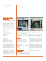
ARDUINO
MATERIA 101
user MANUAL
Revision 02
24 NOVEMBER 2014
2
User Manual
Arduino Materia 101
WELCOME TO 3D PRINTING
ARDUINO.CC/MATERIA101
© 2011-2015 Arduino LLC. All rights reserved.
The Arduino name and logo are trademarks of Arduino, registered in the US
and in the rest of the world.
Other product and company names mentioned herein are trademarks of their
respective companies.
Materia 101 is designed by Sharebot for Arduino.
00
3
User Manual
Arduino Materia 101
INDEX
05
06
07
Technical Support
Technical Specifications
Warning: Temperature
18
04 – Configuring the printer
19
Loading the filament
19
Preparing the printing bed
19
Learning to set up the plate
19
Calibration
20
Regulating final leg of axis Z
08
01 – Preliminary Operations
20
Calibrating axes X and Y
09
The anatomy of the Arduino Materia 101
20
09
Opening the package
Recovering of scraps and usage of
M99 (software calibration)
09
The printers position
20
Squaring off axes X and Y (hardware calibration)
10
Assembling the spool-holder
21
Putting in tension the extruder’s rubber bands
10
Unblocking the extruder
22
05 – Our first print from a SD Card
23
SD card
23
Printing profiles
23
Starting the print
23
Stopping the print
24
Modifying printing parameters
24
Detaching the 3D printed object
25
06 – Creating G-Code files
26
Slic3r
26
Configuring Slic3r
26
Loading the model to print
26
Basic parameters of Slic3r
27
Slicing
28
07 – Materials and printing plate
29
How ABS behaves
29
How PLA behaves
29
How other materials behave
11
02 – The 3D printing Process
12
Model
12
Downloading from internet
12
From a 3D model to a printing file
12
A good STL, a good slicing, a good print
13
Printing file
13
Storing the files
15
03 – LCD panel
16
Informative mode
16
The control knob
16
Access to principal menu
16
1° level active printer
17
1° level printer in print
17
“Prepare” Menu
17
“Tune” Menu
4
User Manual
Arduino Materia 101
31
08 – Consideration about
model orientation
32
Orientation
32
Just one object?
32
Support structures
33
Printing Details
35
09 – Everyday maintenance
36
Cleaning the printer
36
Printing bed
36
Feeding mechanism
36
Nozzle
36
Lubrification
36
Tightening the belts
36
Correct ventilation
37
Updating the firmware
5
User Manual
Arduino Materia 101
TECHNICAL
SUPPORT
If you have any problems in using our printers, the
procedure to be followed is as follows:
— Check the manual and guides available on the web site;
— Contact the dealer from which you purchased the machine;
— Contact technical support by filling out the
form beside remember to fill in all fields.
Our technicians will get in touch with you within 3 working days.
In case your printer should re-enter in the factory to be repaired,
our technical support will give as sign a file number to return
and we will provide all the additional information required.
Attention: the package should be the original
one, penalty forfeiture of the guarantee.
Upon receiving your printer, our technicians will assess whether the
problem stems from a failure, in this case the repair under warranty
will be carried out for free, or by improper use of the printer or by
an improper use of material not approved by Arduino: in the latter
case we will provide you with a quote to request your consent to
repair. For out-of-warranty printers may be required a quote for
the inspection. Troubleshooting is a very important task for us and
we think is necessary to share experiences, problems and solutions.
Because of that please give priority to the use of the forum that
will also allow others to take advantage of our and your efforts.
If you are interested in customized assistance
programs please contact [email protected]
6
User Manual
Arduino Materia 101
TECHNICAL
SPECIFICATIONS
Printing technology:
Fused Filament Fabrication
Mono extruder printing volume:
140 x 100 x 100 mm +/- 5mm
Theorical positioning resolution axes X and Y:
0,06 mm
Positioning resolution axis Z:
0,0025 mm
Extruder hole diameter:
0, 35 mm
Filament to be extruded diameter:
1,75 mm
PLA best extruding temperatures:
200-230°
Tested and supported printing filament:
PLA
Experimented printing filaments:
Cristal Flex, PLA Termosense, Poliuretano
Termoplastico (TPU), PLA Sand, PLA Flex, PET
External Dimensions:
310 x 330 x 350 mm w
Weight:
10 kg
Consuption:
65 watt
Electronic PCB Arduino Mega 2560 with Open Source Firmware
Marlin (link to be decided).
LCD Screen of 20 x 4 with an encoder menu of navigation
Presetted printing values for PLA.
Extruder block with regulation pressure upon filament.
7
User Manual
Arduino Materia 101
ATTENtion
TEMPERATURe
The fusion and extrusion system of the thermoplastic filament
requires a heated end up to temperatures of 250 degrees
and more. The contact, even for a very limited time, with the
heated part causes burns. You must avoid to put your hands
or other body parts in the printing area when printing and
for minutes after the printing process is over. The current
temperature of the extruder is indicated on the LCD screen.
01
8
User Manual
Arduino Materia 101
Preliminar Operations
Your Arduino Materia 101
is equipped with a series
of accessories that
allow you to make it
immediately operative.
9
User Manual
Arduino Materia 101
Anatomy of Arduino
Materia 101
Your professional 3D printer Arduino Materia
101 is a tool of precision, ideated, developed
and assembled in Italy by qualified staff.
Before leaving the factory it was submitted
to a quality control and to a quality test
that guarantees its operation. It’s very
important, before you can use the printer,
knowing all the technical terms used in
this handbook and identify all the specific
components that form a Arduino Materia 101.
2
5
4
3
Fig. 2:
1. Extruder
2. Extruder cable
3. Filament inlet hole
4. Fan for cooling printed material
5. Print bed adjustment screws
Opening the package
Your Arduino Materia 101 is equipped with
a series of accessories that allow you to
make it immediately operative; there is
no software because it is open source and
constantly updated. To download the latest
version, please visit the Arduino website.
With care and without damaging the
packaging, remove the various elements
that hold the printer inside the cardboard
box. Then lift the printer out of the box by
grabbing it by the internal metal frame.
2
4
3
1
1
Fig. 1
Fig. 1:
1. Z axis carriage
2. Glass print bed
3. Clips for print bed
4. Print bed adjustment screws
5. LCD panel
6. ON/OFF switch
5
5
6
IMPORTANT: Do not pull the soft black cord
on the left side that goes to the extruder;
it is a power cord and NOT a handle.
Continue taking the rest of the parts from
box and check if the parts correspond with
the list below.
Warning:
Do not throw away the original
package. You could use it if you have
to repackage the printer or move it.
In the package you will find:
— Assembly kit for spool-holderi
— Power cable
— SD Card with a few objects pre-loaded for you
— USB cable
— Spray
— Glass printing bed
WHERE TO PLACE
THE PRINTER
For proper operation, the printer must work
in a clean and dust-free environment with an
ambient temperature between 5°C and 35°C
Fig. 2
It is also preferable to use a location
away from drafts or air conditioning.
The power switch is located on the front of
the printer. On the bottom of the printer
there is a air intake for the fan that cools the
electronics. This must be left unobstructed.
Remember that the filament (plastic wire)
is usually delivered on a spool and that this
should be put on the spool holder, included
in the package. The recommended position
is behind the printer, on the same level
as the printer, but there are alternative
positions possible if there are any walls or
shelves near the machine. The important
thing is that the wire is easily accessible. You
can even put multiple spools on the spool
holder without any hindrance or prevention
of the filament reaching the extruder. For
this reason, the printer must be placed
in a position that has at least 35 cm of
space in the back or on one of the sides.
10
User Manual
Arduino Materia 101
Assembling the
SPOOL-HOLDER
To assemble the spool-holder please
see chapter 3, figures 9, 10 and 11 of
the assembly manual. Remember that
the wire must run unhindered and
facing the direction of the extruder.
Unblocking the extruder
To avoid damage during transport, the extruder
is secured with clamps. The clamps must
be carefully cut and removed to allow the
extruder to move freely. DO NOT feed the
printer until you have done this step, otherwise
you will damage the motors and mechanics.
Remove all the packaging
inside the machine.
02
11
User Manual
Arduino Materia 101
THE 3D Printing Process
Before you start
printing with your
Arduino Materia 101, it is
important to understand
how you arrive at a
finished object.
12
User Manual
Arduino Materia 101
Before you start printing with your
Arduino Materia 101, it is important to
understand how you arrive at a finished
object. This allows you not only to know
what you need to do to give form and
substance to your ideas, but to identify
any constraints and limitations of the
technology used by the printer.
In the table (Fig.1, page 17) the steps required
make successful 3D print are summarized.
Model
It all starts with creating or downloading
a three-dimensional model of the object
that you want to print. The creation is
done through one of the many modeling
programs available over the internet as
freeware, shareware or software for a fee.
There are many and each of them has
different characteristics. In this respect it is
worth noting that you can have different
modeling requirements and this is reflected
in the variety of applications. Some are
more suited to mechanical design, artistic
modeling, and others for architectural design.
Remember that 3D modeling is primarily
used to create objects that either a machine
can make or for 3d rendering of a 2D
animation or picture. In the first case, the
object is designed to be made in the physical
world and should therefore be subject to
certain limitations that are taken for granted
in the “real world”. For example that a cube
needs 6 sides to be a cube. In the latter,
the aim is to create an image or animation,
nothing more: the model might then be
flawless as a image, but might be physically
impossible to print.
When you choose the program that you want
to use for your models, you must ensure
that it is able to create a file suitable for the
production of a physical object (especially
3D printing). The programs that are made
for rendering and animation might not be
suitable for making 3d printed objects.
Downloading from
internet
The net offers many ready-made 3D models,
but there is a difference between the models
that “look good” and those that “print well”.
A good indicator of an object that is
printable is if it is offered in the STLformat (sites that share or sell printable
objects often use this format).
If there is no STL-file, it is likely that
the intended use of the object is
something besides 3d printing and
the results can not be guaranteed.
From a 3D model to
a printing file
The real “secret” of three-dimensional
printing is the transformation of the
three-dimensional object into a sequence
of two-dimensional slices that, through
overlapping, reconstruct the object. Imagine
a series of slices of bread: The stack rebuilds
the loaf from which they were cut from.
In the case of 3D-printing every slice may
consist of two-dimensional shapes not
connected together, because it is their
addition to the layers below and above
that will amount to a finished object.
Thanks to this breakdown, the objects can be
as complex as desired. The printer will draw
one layer after another without overlap. A
layer shaped like a square or a doodle have
the same difficulty for the printer.
The postprocessing-program takes a bunch
of parameters and applies them in the
process of cutting the 3d model into 2d
slices. This process is simply called “slicing”
and programs that do this are called “slicers”.
To be able to this in a proper manner the
slicer needs a mesh of surfaces shaped like
triangles in 3d space. The mesh has to be
closed and not have any surfaces missing.
The triangle faces should be correctly
oriented, not confusing the “insides” with
the “outsides”. Sometimes the model is
incorrectly made. If it is a small issue, for
example a missing triangle, the program
might be able to fix the issue. Otherwise,
the resulting errors might prevent the
correct reproduction of the object.
A good STL,
a good slicing,
a good print
The STL file is the starting point for the
entire procedure, so anything you do
not want to print should be removed
from the file (hidden objects, etc.).
The 3D drawing must be a solid, not what
only appears to be a solid. Similarly, the
design must be as clean and precise as
possible. Articles must have an inside and
an outside that are well defined so that the
surfaces perfectly match each other without
leaving holes. Most 3D design software gives
you the possibility to carry out an analysis
of borders to check for holes.
The 3D drawing must be oriented in such
a way as to have a face adjacent to the
XY plane of your drawing software. In
other words, the design should not “float
in a vacuum”, otherwise the machine
13
User Manual
Arduino Materia 101
will not print. If you are working on a STL
downloaded from the internet or given to
you by a client, there is free software for
checking and correcting STL-files, such
as Netfabb. The “slices” are printed in a
specific format (called G-code). This format
is nothing more than a set of instructions
for moving the instrument (cutter, laser
or extruder head) along a path (X, Y, and Z
axes). Each slice contains the commands
to move the extruder on the x and y-axis
and extrude the molten plastic to create
one layer after another and finally make
a whole object. At the end of each layer,
the G-code tells the machine to lower the
z-axis just enough to add a new layer.
Materia 101 3d printer and might damage
the printer if you try and print them.
The file also sets temperatures for the
extruder and the heated printing bed,
tying the file not only to the printer
but also to the material being used.
As you shall see in the following pages,
with the LCD Panel, it is possible to modify
some parameters when printing. Arduino
Materia 101 offers you the possibility to
edit the G-code in order to adapt it to
different materials without having to redo
the process of slicing. See table on page 17.
Storing the files
Every 3D object can be transformed
with the process of slicing in a variety
of G-code files, each different from
the others depending on the slicing
parameters being used. For example:
the slices have the inside full, empty or
partially empty, or the walls are made
with one, two, three or more passes.
Even the thickness of each layer is one of
the parameters. The same object can be
printed full, empty, with 100 or 200 slices
and more or less robust and stiff despite
all versions having a similar appearance.
Printing file
The G-code files containing instructions for
moving the various mechanical parts of the
printer according to the specific parameters
and settings have a limited compatibility
between different printers. The STL file of
the template can be used by anyone with a
3D printer to create a printing G-code. The
G-code file works for the printer for which
it was created, but could be unusable with
other printers. G-code files found on the
internet might not be compatible with your
The process consists of the stages:
modeling, creation of STL files, slicing into
a G-code file and print. Save the original
file of the 3D modeling program you use,
so as to keep any primitives (mathematical
descriptions of shapes) that compose
the object. Similarly, the STL files should
be stored in order to slice with different
settings. Save the G-code, even in different
versions for the same model, so you can
repeat a print with specific features used
in that particular G-code file, of which
you already know the final results.
14
User Manual
Arduino Materia 101
Printing Steps Table
Printing Environment
Operation
Output
— Common used CAD software
— Design the object
— Common used format for your file
— Common used CAD software
— Import/save file in .stl format (or .obj)
— File .stl
— Slic3r Software
— Generate command file for3D printer
— File .gcode
— 3D Printer: Arduino Materia 101
— Select file and preloaded filament profile
— Printed object
Fig. 2
03
15
User Manual
Arduino Materia 101
LCD panel
Arduino Materia 101 is
a printer that supports
both stand-alone
operation and control
from a computer (OS
X, Windows or Linux).
In both cases, the
LCD Panel provides
functionality for booth
status and editing.
16
User Manual
Arduino Materia 101
Arduino Materia 101 is a printer that supports
both stand-alone operation and control
from a computer (OS X, Windows or Linux).
In both cases, the LCD Panel provides
functionality for booth status and editing.
INFORMATION SCREEN
When the printer is printing or waiting
for a job, it fills the the screen’s 4 rows
(composed of 20 characters) with
the following information (Fig.1):
The first line contains the extruder’s
actual temperature followed by a zero.
The temperature is in degrees Celsius.
The second line on the left indicates
the current extruder-position in X-and
Y-coordinates, and on the right, you see
the position of the bed, or z-axis. The
value is in millimeters, with two decimals
to indicate hundredths of millimeters.
The third row on the left shows the Feed
Rate percentage of the expected print speed
within the G-code. A lower percentage
will slow down the speed and higher
values increase the speed. You change the
speed by turning the knob on the printer
when you are in the information screen.
Also on the third line, in the center, is the
percentage of the file that has been read
from the SD card. It starts with 0%, then goes
up to 100% when the print is completed.
To the right of this is the elapsed time from
the start of printing, expressed in hours and
minutes.
The fourth line contains messages that
can be generated by the G-code file with
a special command, or the firmware of the
printer in specific situations.
Fig. 1
The control knob
are printing it offers the menu “tune”.
To the right of the display is a knob which
rotates with small clicks and can be pressed
as a button. With this knob you can interact
with Arduino Materia 101: turning it clockwise
will decrease the selected value, turning it
anti-clockwise will increase the selected
value. During menu scrolling, rotation anticlockwise moves the marker downwards,
and clockwise moves it upwards.
The voices and the features available in these
two modes are different and it is important
to know them, to avoid losing time looking
for functions that are in another mode.
When the display is on the information
screen mentioned in the beginning of this
chapter, the rotation of the knob changes
the Feed Rate percentage, increasing or
decreasing the speed of all the movements
and therefore also the printing speed.
ACCESS TO THE
PRINCIPAL MENU
Pressing the knob on the information screen
will access the main menu. Remember that
the menu displayed depends on the state
of the printer. If it is waiting to run a job, it
offers the menu “prepare” and while you
1st level
— Info Screen
— Prepare
— Print from SD
— Reset
1° level printer in print
— Info Screen
— Tune
— Pause Print
— Stop Print
— Reset
“Prepare” Menu
This menu is used to set up and manage
the printer for subsequent operations
such as printing or shutting down.
17
User Manual
Arduino Materia 101
From here you can disable the motor,
set the x, y and z axis to zero, heat and
cool down the extruder, manually move
the different motors on the printer,
and change plastic filament. In the next
chapter you will use this menu to adjust
the level of the printing surface.
The next item is the fan speed, adjustable
from 0 to 255; with very low values the
fan may not even spin. The flow value
set in the G-code is expressed as 100%;
increase or decrease this to adjust for
unforeseen changes (such as forgetting to
declare the correct filament diameter).
The menu consists of:
Concerning the changing of the filament
while printing: the procedure comes from
the need to replace the filament when the
spool is finished, but this option can also be
used to change the color of the filament.
— Disable steppers
— Auto Home
— Preheat
— Cooldown
— Move Axis
— Change Filament
“TUNE” MENU
The “Tune” menu only appears when the
printer is performing a job. When you
are in the information screen and press
the knob, the name “Tune” will appear
at the top of the principal menu.
The tune menu consists of:
— Speed
— Nozzle
— Fan speed
— Flow
— Change filament
Inside, there is an additional menu named
“Speed” that allows us to change the overall
printing speed. The speed is expressed as
a percentage and its function is identical
to the feed rate information on the
information screen and can be altered
in the same manner. Below “Speed”, the
temperature is set for the extruded plastic,
under the item “nozzle”. The value is in
degrees Celsius and any change must be
confirmed by pressing the menu knob.
The procedure starts with moving the
extruder to the parking area, then the
stepper-motor of the extruder expels the
current filament-thread and the internal
buzzer is activated as soon as the extruder
is unloaded. When you have positioned
the new wire in the extruder inlet hole
and it hits the drive gear, you must press
the knob to start pulling the filament and
let it extrude until the old plastic is fully
replaced with the new stock. When the
new filament is flowing well, press the
menu knob again to resume printing.
04
18
User Manual
Arduino Materia 101
CONFIGURING THE PRINTER
Your Arduino Materia
101 is a product built
with care, both in design
and in the assembly
of the machine.
19
User Manual
Arduino Materia 101
Your Arduino Materia 101 is a product built
with care, both in design and in the assembly
of the machine. To keep it in optimal
functionality, it is necessary to compensate
with some everyday adjustments. For
example: due to the expansion and
contraction of the motors, that become
hot and cold in a fluctuating manner.
With each print, the entire machine is subject
to vibrations and movements. In the long
run this can loosen the four screws that
hold the print bed. This leads to not having a
precise uniform distance between the glass
plate and the nozzle of the extruder, which
then inevitably fails to apply the first layer
with the accuracy and uniformity that is
necessary for quality printing. Straight out
of the box, the Arduino Materia 101 should
be calibrated with exact factory settings,
but vibrations from a long journey may
have altered the factory calibration (Fig.1)
Loading the filament
To be able to print you must load a wire
of thermoplastic into the extruder, which
pushes the wire into the “hot-end” and
then becomes fluid, and may be extruded.
The Arduino Materia 101 has a specific
menu option to load or change filament
and it is located under the menu “Prepare”.
When chosen, it starts heating the
extruder and when the right temperature
is reached, you can load or unload the
filament (the procedure is identical to the
option accessible from the menu “Tune”
described in the previous chapter).
It is prohibited by the firmware to
extrude plastic when the hot-end is cold
and filament should not be forced by
pulling or pushing it into the extruder.
Fig. 1
To load the filament in a correct manner,
cut the plastic wire end (to remove
any old melted wire ends), activate the
“change filament” option and make
sure that the wire runs past the feeding
sprocket and into the hole below (Fig.2).
Preparing the
printing bed
Remove the glass print bed from the
printer by releasing the clips. Spray a thin
layer of hair spray evenly over the entire
surface. Now wait for the hairspray to dry
completely and then place the glass on the
print bed and secure it with the binder clips.
Never apply the spray inside the printer
(do it in a well ventilated room, by a
window, or outdoors), this might severely
damage the mechanical components
and void the warranty. After a series of
prints or when the glass plate has bumps
of dirt and residue, remove the glass and
wash it in lukewarm water. Always be
careful when removing the glass plate.
Fig. 2
Position the glass printing bed in the
printer with the two clips, as seen in
picture below. The position of the clips
is not binding or final. As long as they do
not invade any useful print area, you can
change the position based on what you
are printing. The most important thing is
that the nozzle does not hit the clamps.
CALIBRATING THE
BUILD PLATE
This, though initially a bit tiresome, will
become a habit that you do before every
print of higher quality. It will not even take
you a minute when you get used to it. With
experience, you will be able to take action
when printing the first layer if you notice
any irregularities in the plastic being laid
down. In general, it is a good idea to observe
the first layer of the print and take notice
of the shape of the deposited material on
the print surface. It should be pushed “into”
the surface so that it gets a good grip and
does not lose its grip later in the print.
20
User Manual
Arduino Materia 101
ADJUSTING THE AXIS
Z END-STOP
There is a way of adjusting the overall
distance from the nozzle to the print
surface. To do this, adjust the Z axis “endstop” (a simple on-off switch). Turn the
black knob in the back of the machine (see
picture); clockwise to increase the distance
and counterclockwise to decrease the
distance between the surface and nozzle.
On your Arduino Matter 101, it is recommend
that you always have at least one
inch of space on the z-axis adjustment bolt
available, as seen in Fig . 3 (see section 3e
Figures 7 and 8 of the assembly manual).
CALIBRATING THE
X & Y AXIS
There is also, for subsequent regulations that
require only a rapprochement or removal of
the nozzle, the ability to adjust the Z limit,
running ahead or by delaying it. To adjust
the limit switch intervention Z let’s turn
the black knob on bottom of machine (see
picture); clockwise increase the distance
plate-nozzle going to decrease the total
travel of Z, while turning it counterclockwise
decrease the distance plate-nozzle,
lengthening the total travel of Z.
Fig. 3
The first intervention is to check the tension
of the belts on the axis with the backlash,
after that you can use software to correct
the error. In the start of G-code of Slic3r or
the slicing software being used, enter the
command: M99 X0 Y0.2 Z0 E0, where “Y0.2”
stands for the backlash to be compensated
for on the Y-axis. “0.2” stands for 0.2 mm.
Enter the value and use the Materia101_test_
print.zip from our support site to see if the
value inserted is the correct one to remove
the backlash from the axis permanently.
— Squaring off axes X and Y
(hardware calibration)
— Compensation for backlash and
usage of M99 (software calibration)
If your circles are ovals, groups of boxes are
not square or if the infill of the boxes are
not connecting with the outer shell, maybe
you need to realign the X and Y axes.
If you have backlash on the Y or X axis,
you will notice it by looking at any hole or
circle you print. Notice the direction of the
backlash, for example, if the circle appears to
be flatter on the X axis (towards the front of
the printer), as shown in the figure above, it
means that you have backlash on the Y-axis.
To verify that the X and Y axes are
perpendicular, you can use the file
“Materia101_test_print.zip”, downloadable
from our website, which contains a print
of two boxes. After you are done printing
the test, measure the two perpendicular
sides of one of the printed boxes: if they are
still incorrect (not the same length or not
perpendicular) you will have to recalibrate
the X and Y axes. This procedure requires
a certain dexterity and experience on the
machine: If you are not sure about it, avoid
it. Go to the Prepare menu, select “Auto
Home”; Now unscrew the bolt that tightens
the strap on the left shoulder of the machine.
Then slide a single tooth of the belt over
through the shoulder, forwards or backwards,
to correct for un-squareness of the axis;
tighten the belt and repeat the test print.
See Chapter 7, image 17 of the Assembly
Manual for the squaring procedure.
TIGHTENING THE
EXTRUDER SPRINGS
Your Arduino Materia 101 is equipped with a
spring suspended idler. This solution allows
the extruder to compensate for thickness
variations in the filament and give the
same amount of pressure all the time.
The correct pressure from the idler allows
for optimum feeding of the filament to the
extruder. To check if the tension on the springs
are correct, enter the “Prepare” menu and
choose the option “Change filament”. Wait
until the machines ejection cycle is done and
insert the filament. While loading, hold the
filament thread with your fingers and try and
keep it from being pulled into the extruder. If
there is a “slip” of the drive gear (the sprocket
doing the pulling), tighten the springs until
you hear a sound like a “tak tak tak”. This
means that the tension is high enough.
At the same time, the tension on the springs
can not be too high. This is to protect the
motor when it is under stress and reduce
the the risk of the motor losing steps.
05
21
User Manual
Arduino Materia 101
Our first print from a SD Card
If you have followed
the instructions in
this manual, you have
already set up your
Arduino Materia 101.
22
User Manual
Arduino Materia 101
If you have followed the instructions
in this manual, you have already set up
your Arduino Materia 101 by placing it
on a table with the spool holder, you
connected the power supply, turned on
the printer, calibrated the printing bed and
you have also uploaded the plot strand.
Now you can proceed to your first print.
then choose “SD card menu”. Choose
which printing profile you want to use:
choosing “use set g-code parameter””
will print the object with the values
set in the slicing software; choosing
the PLA will print profile with standard
parameters of PLA and similar (extruder
temperature: 220°, 255 or full fan speed).
THE SD card
Once you have selected the profile, the SD
card’s contents are displayed like files and
folders. By turning the knob, you can scroll
down to the file you want. By pressing the
knob you make your selection and start the
print. Your Arduino Materia 101 will begin the
heating procedure and positioning itself at
the home position of the axes, then when it
reaches the correct temperature it will start
with the first layer. Check that the filament
is sticking to the printing surface without
being too flat or only resting like a round
string on the surface. If you have successfully
run the calibration G-code, you will have no
problems. If you have trouble, you should
stop printing and redo the calibration (Fig. 1).
In the box you will find the plastic container
with your SD memory card. On this card
you can put G-code files (see Chapter 2)
that you want to print. Preloaded at the
factory are some sample files that are ready
for printing so you can make your first print
knowing that the file has been prepared with
optimal parameters to get the best result.
Printing profiles
Theoretically, every G-code requires a
specific material that is determined by the
values set by the temperature of the nozzle,
heated bed temperature and fan speeds. To
print the same object in different materials,
one should then create separate files.
To work around this limitation, the Arduino
Materia 101 allows you to select, before
printing, the outline of the material that
you use. In this way, you can create a
generic G-code to be printed with the
chosen material simply by choosing the
corresponding profile. In other words, you do
not need to insert the various temperature
parameters and fan speeds in the slicing
program because they are set correctly when
you choose the desired material profile.
Starting the print
Press the knob again to enter the menu,
Stopping the print
While printing you can pause or
abort printing. The two options are
available directly from the main
menu as “pause” and “stop print”.
It may take a few seconds for the printer
to stop after “pause” is pressed.
In the second case, the printing
stops immediately and for good.
The extruder then goes to the X and
Y home coordinates position.
Unfortunately, the point on the object where
the extruder stops can be affected by heat
and might deform. A runny drop of material
Fig. 1
from the extruder could also form where
the extruder stops. So the pause function
should only be used for short periods of time.
Try and pause it only when the extruder
is tracing the infill so that the drop or
deformation is hidden inside of the object.
Modifying printing
parameters
One of the features of Arduino Materia
101 is the ability to tune a number of
parameters while a print is running.
The “Tune” menu will become available
instead of the “Prepare” (see Chapter 3).
This allows you to adapt the selected
PLA profile or the set G-code values to a
different material with other behaviors
and characteristics (Materials table in
Chapter 7), change the temperature of the
nozzle and print bed, and the fan speed.
Changing the feed rate, you can slow down
or speed up the overall printing speed to
handle any problem, that a certain material
or model might have. It might be that
23
User Manual
Arduino Materia 101
this print requires more time to cool (and
should be printing at a slower rate) or
the model could be achieved at a higher
speed. Another important parameter is
the flow rate that increases or decreases
the amount of material extruded. This is to
compensate for any changes in the diameter
of the filament wire. The flow rate can also
thicken or thin out the walls of the model.
The “Fan Speed” parameter makes
it possible to adjust the airflow
on the object being printed.
Detaching the 3D
printed object
When your print is finished, Arduino Materia
101 lowers the print bed and parks the
extruder. Now you have easy access to the
print surface to detach the finished object.
This is a delicate and inevitable operation.
Because of the way the object is printed, it
is necessary that the first layer adheres well
and remains clinging to the plane for the
duration of the print itself. If the bond was
not good, mechanical stress and vibrations or
even a small nudge from the extruder would
detach the print and consequently ruin it.
Detaching the model thus requires a
certain expertise and some tools such as
a thin spatula or a box cutter (Fig. 2).
Be careful when removing the object
with these tools. It is recommend to
wear protective gloves to avoid cuts
from the blade or the glass plate.
Try and insert the blade a few millimetres
under one side of the printed piece, then
with a horizontal movement, without trying
to lift the piece, move the blade towards
the opposite side of the print. Usually the
piece comes loose without much force and
without you reaching the other side. If the
model has thin leg parts touching the surface,
you should detach these first without lifting
them and then detach the part with the
broadest base. In this way you avoid breaking
the thin parts. In the case of vessels or parts
with a single wide base, start on one side,
trying to insert the blade deeper and deeper.
Do not push the blade directly in but use an
oscillating movement to advance the blade.
Avoid pulling on the printed object or
using it as a lever, because it could break.
If the printed object has a big base surface,
you can remove the glass print plate and
place it under lukewarm water to allow
the hairspray to dissolve and allowing
the easy removement of the object.
Remember that the extruder is warm just
after the print is done.The extruder’s solid
brass nozzle remains hot for several minutes
at temperatures sufficient to cause a burn.
Look at the temperature on the display and
avoid any contact with the nozzle as long as
a it indicates a value higher than 50 degrees.
If in doubt, do not detach the piece until the
temperature has dropped to safe levels.
Fig. 2
06
24
User Manual
Arduino Materia 101
Creating G-Code files
There is a wide range
of programs available
for modeling software
and for slicing software.
They come in free open
source form as well as
paid professional form.
25
User Manual
Arduino Materia 101
There is a wide range of programs available
for modeling software and for slicing
software. They come in free open source
form as well as paid professional form.
Slic3r is a free one and is used as a reference
slicing software. Its versatility makes it
useful for beginners and professionals alike.
SLIC3R
It is made by Alessandro Ranellucci and it is
an open source slicing software. It can be
downloaded from the download section on
www.arduino.cc/Materia101.
At the moment of the writing, the suggested
version is 1.1.5, which is the latest stable
version. Once you have finished the
download, unzip the folder and double
click the icon “Slic3r”. The program will
run without installation. Create a shortcut
on your desktop. During the launch, the
program may ask you to set the data
and the parameters of your printer: click
“cancel” and loaded the Arduino Materia 101
profiles as shown in the next paragraph.
Configuring Slic3r
As a first step, it is recommend that you
switch to expert mode. From the file menu
choose “preferences” and in the drop down
menu select “expert”. To confirm the mode
you need to close and restart the program.
At this point, it is necessary to define the
parameters for the printer. In order to
simplify the process, these are made available
on the arduino web page.They are also part
of the files you already downloaded.
After that, choose “load config ...” from the
File menu; in the folder “profiles” that you
have already downloaded, select the file
“ArduinoMateria101.ini” and, once loaded,
Fig. 1
click on the diskette icon next to the box
with the name of the profile you just loaded.
You must repeat the save operation for
each of the three tabs “Print Settings”,
“Filament settings” and “Printer settings”.
The profile will be available in future
sessions only after saving, otherwise it will
be available only for this session of “Slic3r”.
If you want to create different profiles, you
can modify one parameter and then save
the new configuration with a new name. It
is recommend not to overwrite the profile
already supplied by Arduino (Fig. 1).
Note: try and keep the names of
you configurations descriptive of
the parameters it contains.
Loading the model
to print
In the “Plater” tab, you click on “Add” to add
your 3D model in .stl format; you can also
drag it into the program from an open folder.
Slic3r will center the object automatically,
but it will not automatically lay it down
on the surface. If your .stl file has not been
created with the base of the object on the
zero point of the Z axis, your print will fail.
You can lay out multiple STL’s or repeat the
same STL multiple times. At the beginning, it
is recommend you to try one file at a time.
Basic parameters
of Slic3r
The Arduino Materia 101 allows you (thanks
to ’Use GCODE params” and PLA profiles)
to generate a G-code by setting only the
geometric parameters of your interest. You
can create specific G-code for individual
materials. If you are only using PLA, you do
not need to.
For further information, please consult
the Slic3r manual (manual.slic3r.org).
— Layer height: Inside the tab, “print
settings”, in the menu, “layers and
perimeters”, you will find the item, “layer
height”. This is the height of a single layer
and determines the printing resolution (for
shapes on the z axis) and, consequently,
the printing time. The preset value is
0. 2 mm and is a good compromise
26
User Manual
Arduino Materia 101
between speed and quality, but you can
go down to 0.05 mm or up to 0.35 mm.
— Infill: In the next menu, “infill”, the
parameter “fill density” expresses the
percentage of fill in the printed object. You
can set values from a minimum of 5% to
a maximum of 100%. This parameter will
affect the speed of printing. The lower
the fill, the faster the printing. Obviously,
with a low filling will have a brittle and
light piece. For this, the fill parameter can
be varied depending on the outcome you
want to achieve. The entry, “fill pattern”,
lets you choose the pattern that you
want to fill the object with (rectilinear,
honeycomb, etc.), from a drop down menu.
— Support material: In the menu, “support
material”, you will be able to select the
item, “generate support material”, and
the program will automatically support
areas with overhang (areas of the model
that are suspended or sides that have
an inclination of 45° or greater) with
support towers. Before you select this
option, you should read the details in
Chapter 8 of this manual and evaluate
any workarounds you might implement
(changing orientation of the piece, etc.).
SLICING
Once you input the parameters of your
interest, you can start the slicing process.
Go back to “Plater” tab and click on “export
G-code”. Then you have to select the
destination and the file’s name, and the
process will start. This process could take
a few minutes because it depends on the
parameters chosen and model’s complexity.
When the slicing is over, copy the G-code file
onto the SD Card: you are ready to print.
Fig. 2
07
27
User Manual
Arduino Materia 101
MATERIALS AND PRINTING BED
One of the most critical
elements in current 3D
printers is the superficial
treatment of the printing.
28
User Manual
Arduino Materia 101
One of the most critical parameters of 3D
printing is the surface of the printing bed.
When you extrude first layer of the object,
it is smeared by the brass tip onto the print
surface. If the cooling plastic loses adhesion,
it is very likely that the print will be damaged
before the object is completed. There is
no single solution for all types of filament.
Because of this, we mainly focus on the two
materials most commonly used; PLA and
ABS, and compare these with other materials.
HOW ABS BEHAVES
It is a thermoplastic with characteristics that
can be varied by changing the relationship
between the three main components
(acrylonitrile, Butadiene and styrene) to
obtain a material with more flexibility,
strength, a melting point higher or lower
and even other physical parameters such
as the percentage of thermal retraction/
expansion. ABS is used extensively in
industry with injection moulding of common
everyday objects. It is also the material that
the first RepRap 3D printers were using
to print engineering parts and gears. It
resists high temperatures before softening
and losing its mechanical resistance and
dimensional stability. On the downside it
needs a higher printing temperature of 230
or more degrees Celsius and during cooling
its size reduces noticeably, leading often
to deformation of the first printed layers
and the consequent detachment from the
printing surface. To avoid this phenomenon,
there are two countermeasures to use
in combination. The first one is to have
a surface covered with a material that
has strong adhesion with the ABS. The
second is to keep the heat of the surface
(between 70 and 115 degrees) to allow the
printer to build the entire piece without
thermal retraction being so pronounced.
A piece that is kept in shape with these two
countermeasures throughout the print will
be far more dimensionally accurate with
the 3d model. Often, however, it happens
that there is a partial detachment on thin
parts, elongated with significant coverage
of the bed. In these cases, the printing is
completed but the deformed parts might
be arching upwards. This is called warping.
The material, which at the moment is very
handy for keeping the ABS attached to the
printing plate, is the hairspray. Its watersoluble components allow you to create a
surface that adheres to the glass sheet and at
the same time blends and binds with the ABS,
keeping it firmly stuck in place. To remove the
printed part, use a utility knife or spatula. If
these do not “cut it” and you can not remove
the piece (a testament of the good bond
between the hairspray and the ABS), you
can remove the glass tray from the printer
and put it under water to soften the lacquer
until the piece will come off with ease.
HOW PLA BEHAVES
This material is created by processing plant
pulp waste rich in cellulose. It is preferred by
many, over ABS, even though temperatures
over 60° tend to make it soft. It prints at
temperatures between 180 and 230 degrees
depending on the additives that have been
added to color it and modify its physical
and mechanical properties. In relation to
ABS, it is more environmentally friendly and
emits almost no smell when printing. The
surfaces of the objects printed with PLA are
more reflective and transparent. Also the
size fluctuation is much less noticeable with
PLA, thanks in part to the lower extrusion
temperature. Unfortunately, the range of
temperatures in which the PLA remains
elastic is wide: so if the piece in print is
not properly cooled, there is a risk that it
might lose it structural integrity and appear
deformed or lose all smaller details.
For optimal adhesion of PLA, spray the
glass with hairspray outside of the printer
and return it to the printer. For items with
a base of a significant area, you should
use a preheated plate at 60°. This is a
good hack to add to your Materia 101. If
you add a heated bed you also have to
add a more powerful power supply.
HOW OTHER MATERIALS
BEHAVE
The behavior of other materials
can be related to PLA and ABS.
See the examples in the table
on the next page.
29
User Manual
Arduino Materia 101
Attributable PLA
Tips
Material
Attributable ABS
HIPS
Extrusion temperature: 235°
Plate temperature 90°
Fan Off
Smart ABS
Extrusion temperature : 260°
Plate temperature: 90°
Fan Off
Nylon
Extrusion Temperature 240°-265°
Plate Temperature: 90°
Printable perfectly on garolite
phenolics.
PET
Extrusion temperature 220°-230°
Plate temperature 60°
Fan at 100%
Thermosense
Extrusion temperature 210°-220°
Plate temperature 50°
Fan at 100%
Cristal Flex
Extrusion temperature 220°-240°
Plate temperature 60°
Fan at 100%
PLA Flex
Extrusion temperature 230°-240°
Plate temperature 90°
Fan at 100%
TPU
Extrusion temperature: 240°
Not Heated Plate
Fan at 50%
Table of Materials
08
30
User Manual
Arduino Materia 101
CONSIDER THE MODELS ORIENTATION
The possibilities offered
by your Arduino Materia
101 are very broad, but
like all tools, it has its
limitations. This must
be understood and
various countermeasures
must be implemented
to deal with these.
31
User Manual
Arduino Materia 101
The possibilities offered by your Arduino
Materia 101 are very broad, but like all
tools, it has its limitations. This must be
understood and various countermeasures
must be implemented to deal with these. 3D
printing technology promises to create any
shape but there are frequent cases where
a print ends with a big disappointment.
Orientation
Start with considering the orientation of the
object in relation to the direction of how
the printer builds it. The object is created
in layers and each layer is created so that it
overlaps the previous one. When a wall or
a surface is tilted more than 45 degrees or
some parts do not have anything beneath
them in the previous layers, the first question
to ask yourself concerns the possibility
to rotate the model to solve the issues of
tilted surfaces and free hanging details.
You might need to spin the object by 90
or 180 degrees, thus changing the portion
resting on the print surface. In general, if
you can find an orientation that allows a
reasonable flat surface to be in contact with
the print surface, you are ensuring that the
print does not come loose during the print.
Take the example of a door printed in
its natural position (vertical). The base
would be a very small area as opposed
to laying it down where the base
would be much bigger and less likely
to release from the print surface.
Maybe small details (such as the handle,
for example) do not allow the construction
of the door laying down. In this case, it
is recommended that you remove the
handle and print it separately. After they
are both printed, attach it with a little
Fig. 1
glue in its original position. An excellent
example of how the orientation can
make a printable object without any
problems (or adding media) can be found
at www.thingiverse.com/thing:37978.
It is a house-shaped lamp (Fig. 1).
Just one object?
There are cases when printing the object in
one piece is unavoidable but there are as
many cases where you can and should cut
it into several parts so that the object can
print easier. An example of this that you
often see on the internet is the Eiffel Tower.
If you would print the whole small-scaled
model of the tower in one piece, then the
resulting object would be very small and
have very tiny details and this might not
be what you want. Besides, some of the
details might get lost when printing a model
in one piece. When cutting the model into
two or three parts, it is possible make a
bigger print with a smaller printer and get
finer details. The finished parts can easily be
assembled with a drop of glue and then you
have got a perfectly printed Eiffel tower.
Fig. 2
SUPPORT STRUCTURES
If plastic being suspended in mid air is
unavoidable then you have to use some kind
of support for this part. A bunch of tilted
geese, for example, only have a very small
area to start the print on. The supports
are the solution that has technology
developed to overcome the force of gravity
and allow the creation of complex models.
Another example would be suspended
parts and other parts (balls of a bearing)
with items that necessarily begin (moving
upwards) from nothing, such as arms not
placed on the hips in a figure (Fig. 2).
If the problem can only be linked to one
detail, then you can create a solution in the
model. Take the case of this famous model.
Thanks to an enterprising user, the model
was only modified with the addition of a
support necessary to achieve a flawless
printing. The lower part of the chin was
started from an added support that is
a tenth of a millimeter (Fig. 3 and 4).
In this way, a print that needs some
32
User Manual
Arduino Materia 101
attention and has a critical point can still
become a print with a guaranteed result.
The support is generated by the slicing
software if it is enabled at the creation of
the print parameters. Depending on the
parameters and the shape of the model, you
can create a support structure. At the end
of printing, with some patience, you remove
these structures and the piece remains
clean and has the shape you wanted. Here
is an example of an object that requires
the supports accompanied by the G-code
and is generated with these supports.
Fig. 3
Fig. 4
The supports are vertical structures under the
cheekbones and on the inside of the orbits.
Keep in mind that the surfaces of contact
between the support and the model will have
a very low surface finish to make certain
that the two areas are merged together. This
will require a finishing touch to remove the
backing material and create a finished look (if
deemed necessary). In professional printers,
supports are manufactured using special
thermoplastic made by a second extruder.
Later, these supports are dissolved with a
special chemical or with thermal baths.
Printing Details
When you prepare an object for
printing, you define various parameters
including the thickness of each layer.
This value has a significant impact on the
resolution of the object for all surfaces
that grow upwards at an angle.
Imagine an inclined plane and mentally slice
it. The size of the slices can vary a lot and
if they are drawn with a fixed line width,
you can open the spaces between one
layer and the next. If the number of slices
increase, they are thinner so the inclination
is defined in a smoother manner. For this
reason also, the Z-axis resolution is spoken
of as the main resolution of 3D printers.
A side effect of a thinner layer height is
that it takes greater amounts of time. In
other words, a greater amount of layers
to print equals more area to cover. On
the other hand, the quality is going to be
better and layers might bond better.
Each type of object has its own range of
optimum thickness for printing and you
will learn how this parameter interacts
with the object. A tip is to choose a small
but articulated shape that you can pursue
with systematic experimentation. Practice
with this and you will be able to see the
effect of each variation. The definition on
the two axes, X and Y, it is not controllable
by the user. This is a product of the model’s
geometry, which is composed of triangles.
If the amount of triangles describing a
circle is low, that could show facets in
place of soft surfaces and well rounded
curves. More triangles bring greater detail.
A larger amount of triangles means a
larger job for the slicing software and if
the triangles are in the tens of thousands,
then they can even cause processing
problems. As you can guess, above a certain
level the details are no longer recreated
by the printer and then they are basically
useless. Or, rather, are only significant
when blowing up the detail of a model. To
reduce the number of triangles describing
the 3D model, there are several programs
and even Slic3r itself provides an option. It
that allows you to define a size threshold
for details to go ignored or simplifying and
this will speed up the slicing of the model.
It should be also considered that the
recommended minimum thickness
of the walls is 1.05 mm on the
vertical axes, consisting of three
lines of plastic (perimeters).
09
33
User Manual
Arduino Materia 101
EVERYDAY MAINTENANCE AND CLEANING THE PRINTER
Arduino Materia 101
does not require any
special maintenance,
but like all machinery,
efficiency is at its highest
if it is kept clean.
34
User Manual
Arduino Materia 101
EVERYDAY MAINTENANCE AND
CLEANING THE PRINTER
tak”). The springs should not be too tight.
Avoid putting the motor under too much
strain and consequently losing steps.
Arduino Materia 101 does not require any
special maintenance, but like all machinery,
efficiency is at its highest if it is kept clean.
THE NOZZLE
THE PRINTING BED
The first layer of the object you print is
essential to the success of the print. For
this reason, the print bed must be perfectly
smooth with a uniform layer of hair spray
applied. After many prints, overlapping
layers of hairspray together with residue
from earlier printing might compromise
the flatness of the glass print surface,
creating irregularities. It is easy to carefully
remove this with lukewarm water and
applying a new surface of hairspray.
FEEDING MECHANISM
The drive gear (or sprocket) of the extruder
and its cushioned pulley tend to “eat” or
chew on the filament. For a perfect feed
of filament, it is necessary to remove
accumulated dust or other debris left
on the pulley and on the drive gear.
If you want to do a thorough cleaning,
unscrew the 4 lateral screws (those
with springs) and sweep away residue
from its bearing. After this you can
reinstall everything and run the
filament through the mechanism.
During the loading of the filament, try and
secure the wire with your fingers; if this
were to cause a “slip” of the drive gear on
the filament, the springs must be tightened
until you hear the motor losing a step
(you should hear a sound like a “tak tak
If you want to remove plastic residue
on the tip of the nozzle; go to “Prepare”
menu and choose “Preheat”, then select
“move axis” and extrude about a half of
a finger length of material or until it pulls
the leftover material away from the tip.
Now select “cool down” and when the
temperature of the nozzle is between 100150°C, remove the dribble of plastic that
hangs from the nozzle with tweezers.
LUBRIFICATION
This is required only after intensive
use of the machine (or early on if it is
used in a dusty environment -strongly
discouraged!-). In any case, the machine
itself starts to ask for oil when it starts to
whine and whistle during operations
Apply a drop of sewing machine oil
or petroleum jelly on the Z, X and
Y guide rods. Spread the oil on the
whole length of the guide rod.
TENSIONING THE BELTS
A well tuned machine should have well
tensioned belts. To tighten the belts on the
y-axis, adjust the screws placed on the top
of the “shoulders”: clockwise will increase
the tension and vice versa. To tension X-axis
belts, adjust the two screws fastening the
y-engine on the right side of the machine:
first it must be loosened in order to move
the engine downwards and so increasing
the belt tension. When you have the perfect
tension, tighten the two screws firmly. To
tighten the belt for the x-axis the procedure
is similar: loosen the stepper motor’s
two screws (on the right shoulder of the
machine), move the engine to get the correct
tension and tighten the two allen screws.
A CORRECT VENTILATION
After leaving your printer on for long hours
you might notice that it is equipped with a
fan to cool the electronics. It is located on
the bottom of the machine, in the center
of the bottom plate. You should make sure
that no debris or dust obstruct this fan.
The extruder motor has a fan dedicated for
its cooling. The heat might be transferred
to the drive gear without this fan. This,
in turn, would make the drive gear
lose its grip on the filament strand.
The fan cooling the extruder motor must
always be on when the machine is in motion.
Updating the firmware
Arduino Materia 101 uses open firmware
and receives frequent updates. Periodically
check our website for updates to keep
your Arduino Materia 101 up to date with
bugfixes and improvements. Instructions
on how to update the firmware is
provided along with the firmware. If your
printer is behaving strangely or does not
correspond to the behaviour mentioned
in the manual, contact our support
service and describe the problem. It might
require an update of the firmware.