1
BreezeNET® B130/B300 GigE
Operational User Manual
Software Version: 1.3
July 2010
P/N 215739
Document History
Document History
Changed Item
Description
Date
First revision
Document’s first revision
April 2009
Second revision
Added BNB 130
November 2009
Third revision
Added GigE support
July 2010
Alvarion BreezeNET B130/B300 GigE
ii
Operational User Manual
Legal Rights
Legal Rights
© Copyright 2010 Alvarion Ltd. All rights reserved.
The material contained herein is proprietary, privileged, and confidential and
owned by Alvarion or its third party licensors. No disclosure thereof shall be made
to third parties without the express written permission of Alvarion Ltd.
Alvarion Ltd. reserves the right to alter the equipment specifications and
descriptions in this publication without prior notice. No part of this publication
shall be deemed to be part of any contract or warranty unless specifically
incorporated by reference into such contract or warranty.
Trade Names
Alvarion®, BreezeCOM®, WALKair®, WALKnet®, BreezeNET®, BreezeACCESS®,
BreezeMANAGE™, BreezeLINK® and/or other products and/or services referenced
here in are either registered trademarks, trademarks or service marks of Alvarion
Ltd.
All other names are or may be the trademarks of their respective owners.
Statement of Conditions
The information contained in this manual is subject to change without notice.
Alvarion Ltd. shall not be liable for errors contained herein or for incidental or
consequential damages in connection with the furnishing, performance, or use of
this manual or equipment supplied with it.
Warranties and Disclaimers
All Alvarion Ltd. ("Alvarion") products purchased from Alvarion or through any of
Alvarion's authorized resellers are subject to the following warranty and product
liability terms and conditions.
Exclusive Warranty
(a) Alvarion warrants that the Product hardware it supplies and the tangible
media on which any software is installed, under normal use and conditions, will
be free from significant defects in materials and workmanship for a period of
fourteen (14) months from the date of shipment of a given Product to Purchaser
(the "Warranty Period"). Alvarion will, at its sole option and as Purchaser's sole
remedy, repair or replace any defective Product in accordance with Alvarion'
standard R&R procedure.
(b) With respect to the Firmware, Alvarion warrants the correct functionality
according to the attached documentation, for a period of fourteen (14) month from
invoice date (the "Warranty Period")". During the Warranty Period, Alvarion may
release to its Customers firmware updates, which include additional performance
Alvarion BreezeNET B130/B300 GigE
iii
Operational User Manual
Legal Rights
improvements and/or bug fixes, upon availability (the "Warranty"). Bug fixes,
temporary patches and/or workarounds may be supplied as Firmware updates.
Additional hardware, if required, to install or use Firmware updates must be
purchased by the Customer. Alvarion will be obligated to support solely the two (2)
most recent Software major releases.
ALVARION SHALL NOT BE LIABLE UNDER THIS WARRANTY IF ITS TESTING
AND EXAMINATION DISCLOSE THAT THE ALLEGED DEFECT IN THE PRODUCT
DOES NOT EXIST OR WAS CAUSED BY PURCHASER'S OR ANY THIRD
PERSON'S MISUSE, NEGLIGENCE, IMPROPER INSTALLATION OR IMPROPER
TESTING, UNAUTHORIZED ATTEMPTS TO REPAIR, OR ANY OTHER CAUSE
BEYOND THE RANGE OF THE INTENDED USE, OR BY ACCIDENT, FIRE,
LIGHTNING OR OTHER HAZARD.
Disclaimer
(a) The Software is sold on an "AS IS" basis. Alvarion, its affiliates or its licensors
MAKE NO WARRANTIES, WHATSOEVER, WHETHER EXPRESS OR IMPLIED,
WITH RESPECT TO THE SOFTWARE AND THE ACCOMPANYING
DOCUMENTATION. ALVARION SPECIFICALLY DISCLAIMS ALL IMPLIED
WARRANTIES OF MERCHANTABILITY AND FITNESS FOR A PARTICULAR
PURPOSE AND NON-INFRINGEMENT WITH RESPECT TO THE SOFTWARE.
UNITS OF PRODUCT (INCLUDING ALL THE SOFTWARE) DELIVERED TO
PURCHASER HEREUNDER ARE NOT FAULT-TOLERANT AND ARE NOT
DESIGNED, MANUFACTURED OR INTENDED FOR USE OR RESALE IN
APPLICATIONS WHERE THE FAILURE, MALFUNCTION OR INACCURACY OF
PRODUCTS CARRIES A RISK OF DEATH OR BODILY INJURY OR SEVERE
PHYSICAL OR ENVIRONMENTAL DAMAGE ("HIGH RISK ACTIVITIES"). HIGH
RISK ACTIVITIES MAY INCLUDE, BUT ARE NOT LIMITED TO, USE AS PART OF
ON-LINE CONTROL SYSTEMS IN HAZARDOUS ENVIRONMENTS REQUIRING
FAIL-SAFE PERFORMANCE, SUCH AS IN THE OPERATION OF NUCLEAR
FACILITIES, AIRCRAFT NAVIGATION OR COMMUNICATION SYSTEMS, AIR
TRAFFIC CONTROL, LIFE SUPPORT MACHINES, WEAPONS SYSTEMS OR
OTHER APPLICATIONS REPRESENTING A SIMILAR DEGREE OF POTENTIAL
HAZARD. ALVARION SPECIFICALLY DISCLAIMS ANY EXPRESS OR IMPLIED
WARRANTY OF FITNESS FOR HIGH RISK ACTIVITIES.
(b) PURCHASER'S SOLE REMEDY FOR BREACH OF THE EXPRESS
WARRANTIES ABOVE SHALL BE REPLACEMENT OR REFUND OF THE
PURCHASE PRICE AS SPECIFIED ABOVE, AT ALVARION'S OPTION. TO THE
FULLEST EXTENT ALLOWED BY LAW, THE WARRANTIES AND REMEDIES SET
FORTH IN THIS AGREEMENT ARE EXCLUSIVE AND IN LIEU OF ALL OTHER
WARRANTIES OR CONDITIONS, EXPRESS OR IMPLIED, EITHER IN FACT OR BY
OPERATION OF LAW, STATUTORY OR OTHERWISE, INCLUDING BUT NOT
Alvarion BreezeNET B130/B300 GigE
iv
Operational User Manual
Legal Rights
LIMITED TO WARRANTIES, TERMS OR CONDITIONS OF MERCHANTABILITY,
FITNESS FOR A PARTICULAR PURPOSE, SATISFACTORY QUALITY,
CORRESPONDENCE WITH DESCRIPTION, NON-INFRINGEMENT, AND
ACCURACY OF INFORMATION GENERATED. ALL OF WHICH ARE EXPRESSLY
DISCLAIMED. ALVARION' WARRANTIES HEREIN RUN ONLY TO PURCHASER,
AND ARE NOT EXTENDED TO ANY THIRD PARTIES. ALVARION NEITHER
ASSUMES NOR AUTHORIZES ANY OTHER PERSON TO ASSUME FOR IT ANY
OTHER LIABILITY IN CONNECTION WITH THE SALE, INSTALLATION,
MAINTENANCE OR USE OF ITS PRODUCTS.
Limitation of Liability
(a) ALVARION SHALL NOT BE LIABLE TO THE PURCHASER OR TO ANY THIRD
PARTY, FOR ANY LOSS OF PROFITS, LOSS OF USE, INTERRUPTION OF
BUSINESS OR FOR ANY INDIRECT, SPECIAL, INCIDENTAL, PUNITIVE OR
CONSEQUENTIAL DAMAGES OF ANY KIND, WHETHER ARISING UNDER
BREACH OF CONTRACT, TORT (INCLUDING NEGLIGENCE), STRICT LIABILITY
OR OTHERWISE AND WHETHER BASED ON THIS AGREEMENT OR
OTHERWISE, EVEN IF ADVISED OF THE POSSIBILITY OF SUCH DAMAGES.
(b) TO THE EXTENT PERMITTED BY APPLICABLE LAW, IN NO EVENT SHALL
THE LIABILITY FOR DAMAGES HEREUNDER OF ALVARION OR ITS EMPLOYEES
OR AGENTS EXCEED THE PURCHASE PRICE PAID FOR THE PRODUCT BY
PURCHASER, NOR SHALL THE AGGREGATE LIABILITY FOR DAMAGES TO ALL
PARTIES REGARDING ANY PRODUCT EXCEED THE PURCHASE PRICE PAID
FOR THAT PRODUCT BY THAT PARTY (EXCEPT IN THE CASE OF A BREACH OF
A PARTY'S CONFIDENTIALITY OBLIGATIONS).
Disposal of Electronic and Electrical Waste
Disposal of Electronic and Electrical Waste
Pursuant to the WEEE EU Directive electronic and electrical waste must not be disposed of with
unsorted waste. Please contact your local recycling authority for disposal of this product.
Alvarion BreezeNET B130/B300 GigE
v
Operational User Manual
Important Notice
Important Notice
This user manual is delivered subject to the following conditions and restrictions:
This manual contains proprietary information belonging to Alvarion Ltd. Such
information is supplied solely for the purpose of assisting properly authorized
users of the respective Alvarion products.
No part of its contents may be used for any other purpose, disclosed to any
person or firm or reproduced by any means, electronic and mechanical,
without the express prior written permission of Alvarion Ltd.
The text and graphics are for the purpose of illustration and reference only.
The specifications on which they are based are subject to change without
notice.
The software described in this document is furnished under a license. The
software may be used or copied only in accordance with the terms of that
license.
Information in this document is subject to change without notice. Corporate
and individual names and data used in examples herein are fictitious unless
otherwise noted.
Alvarion Ltd. reserves the right to alter the equipment specifications and
descriptions in this publication without prior notice. No part of this
publication shall be deemed to be part of any contract or warranty unless
specifically incorporated by reference into such contract or warranty.
The information contained herein is merely descriptive in nature, and does not
constitute an offer for the sale of the product described herein.
Any changes or modifications of equipment, including opening of the
equipment not expressly approved by Alvarion Ltd. will void equipment
warranty and any repair thereafter shall be charged for. It could also void the
user's authority to operate the equipment.
Alvarion BreezeNET B130/B300 GigE
vi
Operational User Manual
Contents
Contents
Chapter 1 - Introduction .......................................................................... 1
1.1 General Notes .............................................................................................................3
1.2 IP-Address Format .....................................................................................................4
Chapter 2 - General Purpose Command Set ........................................... 5
2.1 Help Command ...........................................................................................................7
2.2 System Command ......................................................................................................8
2.3 Set Command (Time Zone Settings).......................................................................11
2.4 Config Command (Configuration Manipulations) .................................................12
2.5 Flashnet Command (Firmware Uploading) ............................................................14
2.6 Restart Command ....................................................................................................15
2.7 Ping Command .........................................................................................................16
2.8 Telnet Command ......................................................................................................17
2.9 Tracert Command.....................................................................................................18
2.10 Webcfg (Web Interface Support) ............................................................................19
2.11 Rshd Command (Remote Shell) .............................................................................20
2.12 Ipstat Command (IP-Statistics)...............................................................................22
2.13 Sflowagent (Sflow Agent) .......................................................................................25
2.14 Acl Command (Access Control Lists) ...................................................................28
2.15 Sntp Command ........................................................................................................30
2.16 Date Command ........................................................................................................32
2.17 License Command ...................................................................................................33
2.18 Dport Command.......................................................................................................34
2.19 Mem Command ........................................................................................................35
Alvarion BreezeNET B130/B300 GigE
vii
Operational User Manual
Contents
Chapter 3 - Layer 2 Command Set - PHY and MAC............................... 36
3.1 Rfconfig Command (Radio Interface Configuration) ............................................38
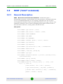
3.2 MINT (“mint” command) ..........................................................................................42
3.2.1 General Description ..........................................................................................42
3.2.2 General Commands Description .......................................................................43
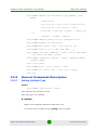
3.2.3 Nodes Authentication ........................................................................................50
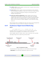
3.2.4 Automatic Over-the-Air Firmware Upgrade.......................................................53
3.2.5 Over-the-Air Encryption.....................................................................................54
3.2.6 Learning the Connection ...................................................................................55
3.2.7 Continuous Signal Levels Monitoring................................................................57
3.2.8 Frequency Roaming..........................................................................................58
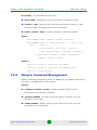
3.2.9 Remote Command Management ......................................................................59
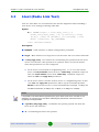
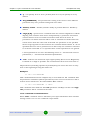
3.3 Ltest (Radio Link Test).............................................................................................61
3.4 Muffer Command (Environment Analyzer) ............................................................66
3.4.1 Review Mode ....................................................................................................66
3.4.2 MAC|MAC2|MAC3|MYNET Modes ...................................................................67
3.4.3 Scan Mode ........................................................................................................68
3.4.4 Statistics Module ...............................................................................................69
3.4.5 Spectrum Analyzer Mode..................................................................................71
3.5 Arp Command (ARP Protocol) ................................................................................74
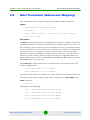
3.6 Macf Command (Addresses Mapping) ...................................................................76
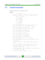
3.7 Switch Command .....................................................................................................79
3.7.1 Wildcard Format................................................................................................81
3.7.2 List Configuration Commands...........................................................................81
3.7.3 Groups Configuration Commands.....................................................................83
3.7.4 Rules Configuration Commands .......................................................................91
3.7.5 Control Commands ...........................................................................................93
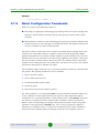
3.7.6 Sample Configuration........................................................................................97
3.8 Dfs (Dynamic Frequency Selection) .......................................................................99
3.8.1 DFS Leader/Client Configuration ....................................................................100
Alvarion BreezeNET B130/B300 GigE
viii
Operational User Manual
Contents
Chapter 4 - Layer 3 Command Set - IP Networking ............................ 102
4.1 Ifconfig Command (Interfaces Configuration).....................................................104
4.2 Tun Command (Tunnels Building)........................................................................107
4.3 Qm Command (QoS Configuration) .....................................................................111
4.4 Route Command (Static Routes Configuration)..................................................120
4.5 ARIP.........................................................................................................................122
4.5.1 Getting Started ................................................................................................122
4.5.2 Command language. Basic Principles ............................................................122
4.5.3 Start/Stop of RIP .............................................................................................125
4.5.4 Filters ..............................................................................................................126
4.5.5 RIP Configuration............................................................................................128
4.5.6 Route Map (route-map)...................................................................................130
4.5.7 Authentication. Identity Check.........................................................................132
4.5.8 Timers Configuration.......................................................................................133
4.5.9 Configuration View ..........................................................................................134
4.6 ARDA .......................................................................................................................135
4.6.1 Getting Started ................................................................................................135
4.6.2 Command Language. Basic Principles ...........................................................135
4.6.3 Start/Stop of ARDA .........................................................................................137
4.6.4 Filters ..............................................................................................................137
4.6.5 Creating Static Routes ....................................................................................139
4.6.6 Interface Management ....................................................................................140
4.6.7 Configuration View ..........................................................................................140
4.7 OSPFv2 (Dynamic Routing Protocol Module) .....................................................141
4.7.1 Getting Started ................................................................................................141
4.7.2 Command Language. Basic Principles ...........................................................141
4.7.3 Start/Stop of OSPF .........................................................................................145
4.7.4 Router Identifier...............................................................................................145
4.7.5 Filters ..............................................................................................................145
4.7.6 Link State Advertisement ................................................................................148
4.7.7 Link Metric.......................................................................................................152
4.7.8 OSPF System Areas .......................................................................................153
4.7.9 Authentication. Identity Check.........................................................................159
Alvarion BreezeNET B130/B300 GigE
ix
Operational User Manual
Contents
4.7.10 Router Running Configuration View................................................................161
4.8 Netstat Command (Network Statistics) ................................................................169
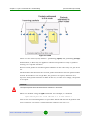
4.9 Ipfw Command (IP Firewall) ..................................................................................171
4.9.1 General Description ........................................................................................171
4.9.2 Packet Filtering Rules .....................................................................................174
4.9.3 Packet Filtering Rules Syntax .........................................................................176
4.9.4 Examples of Packets Filtering.........................................................................180
4.10 Loadm Command (Load Meter) ............................................................................188
4.11 Bpf Command (Berkeley Packet Filter) ...............................................................190
4.12 Snmpd Command (SNMP Daemon) .....................................................................192
4.13 Td Command (Telnet Daemon).............................................................................194
4.14 Nat Command (Network Address Translation) ...................................................195
4.14.1 General Description ........................................................................................197
4.14.2 Commands Description...................................................................................197
4.15 Trapd Command (SNMP Trapd Support).............................................................205
4.16 DHCP Server ..........................................................................................................207
4.16.1 DHCP Server Command Language................................................................207
4.17 DHCP Relay. dhcpr Command .............................................................................230
4.17.1 General Description ........................................................................................230
4.17.2 Commands Description...................................................................................230
4.18 DHCP Client. dhcpc Command ............................................................................232
4.18.1 General Description ........................................................................................232
4.18.2 Options............................................................................................................232
4.18.3 Commands......................................................................................................233
4.18.4 Examples ........................................................................................................233
4.19 DNS Client ..............................................................................................................234
4.20 Nslookup ................................................................................................................235
Alvarion BreezeNET B130/B300 GigE
x
Operational User Manual
List of Tables
List of Tables
Table 3-1: “rf stat” output for 5GHz devices ................................................................................ 40
Table 4-1: Compliance Scheme of MINT and IEEE 802.1p Priorities ....................................... 116
Table 4-2: Standard Access Lists.............................................................................................. 126
Table 4-3: Extended Access Lists ............................................................................................. 127
Table 4-4: Nominate Access Lists............................................................................................. 127
Table 4-5: Prefix Lists ............................................................................................................... 128
Table 4-6: Standard Access Lists.............................................................................................. 138
Table 4-7: Extended Access Lists ............................................................................................. 138
Table 4-8: Nominate Access Lists............................................................................................. 139
Table 4-9: Standard Access Lists.............................................................................................. 146
Table 4-10: Extended Access Lists ........................................................................................... 147
Table 4-11: Nominate Access Lists........................................................................................... 147
Table 4-12: Prefix Lists ............................................................................................................. 147
Alvarion BreezeNET B130/B300 GigE
xi
Operational User Manual
List of Figures
List of Figures
Figure 2-1: Mem Command ........................................................................................................ 35
Figure 3-1: Mint Map Output ....................................................................................................... 55
Figure 3-2: Mint Map Routes Output ........................................................................................... 56
Figure 3-3: Mint Map Swg Output ............................................................................................... 56
Figure 3-4: Mint Monitor Output .................................................................................................. 57
Figure 3-5: Ltest Output .............................................................................................................. 63
Figure 3-6: Ltest Align Output ..................................................................................................... 63
Figure 3-7: Ltest Bandwidth Output ............................................................................................ 65
Figure 3-8: Muffer Review Mode ................................................................................................. 67
Figure 3-9: Muffer MAC2 Mode................................................................................................... 68
Figure 3-10: Muffer Scan Mode................................................................................................... 69
Figure 3-11: Muffer Statistics Module.......................................................................................... 70
Figure 3-12: Muffer Spectrum Analyzer Mode ............................................................................ 72
Figure 3-13: Switch Group STP Output....................................................................................... 89
Figure 3-14: Switch IGMP Snooping Dump Output..................................................................... 96
Figure 4-1: Tunnels Between Physically Separated Networks.................................................. 107
Figure 4-2: Tunnels Inside the Same Network .......................................................................... 108
Figure 4-3: Qm .......................................................................................................................... 119
Figure 4-4: ARIP Transition....................................................................................................... 123
Figure 4-5: OSPF Transition ..................................................................................................... 142
Figure 4-6: Netstat Output......................................................................................................... 169
Figure 4-7: Netstat -i Output...................................................................................................... 170
Figure 4-8: IPFW ....................................................................................................................... 172
Figure 4-9: IP Spoofing ............................................................................................................. 183
Figure 4-10: Loadm Output ....................................................................................................... 189
Alvarion BreezeNET B130/B300 GigE
xii
Operational User Manual
Chapter
1
Introduction
Chapter 1 - Introduction
In This Chapter:
“General Notes” on page 3
“IP-Address Format” on page 4
Alvarion BreezeNET B130/B300 GigE
2
Operational User Manual
Chapter 1 - Introduction
1.1
General Notes
General Notes
This manual lists the commands of the WANFleX operating system.
For device's management and configuration a Unix-like command line interface is
used. Every command is having power right after Enter key is pressed. However,
each command lifetime duration is limited within one configuration session. In
order to save a current configuration "config save" command is used.
Several commands can be grouped in one line using ";" character. If a
wrong-syntax line is met in the group, the rest of the string is checked anyway
and the wrong command is ignored. Command name can be shortened unless the
ambiguity occurs.
If your terminal supports VT100 or ANSI standard you can move around the list of
recently executed commands using cursor keys. Numbered list of these
commands can be reviewed by "!h" command. Any command from this list can be
available using "!<NUMBER>" command. TAB key performs substring search of
recently executed commands.
Ctrl/R combination refreshes the command string if its content was disturbed by
system messages.
The command executed with no arguments prints a short hint about its keys,
parameters and syntax.
Context help can be obtained by printing "?" in any position of the line.
Alvarion BreezeNET B130/B300 GigE
3
Operational User Manual
Chapter 1 - Introduction
1.2
IP-Address Format
IP-Address Format
Many commands of the operating system require specification of IP-addresses.
In OS WANFleX, the IP-addressees may be specified in traditional numeric format.
Optionally, the mask may be specified either by its bit length (the specified
number of leading bits in the mask are set to 1, the remaining bits are reset to 0)
or numeric value. The IP-address 0/0 denotes all possible IP-addresses.
Therefore, the possible formats to specify IP-addresses are:
nn.nn.nn.nn (no mask is used)
nn.nn.nn.nn/N (N is the bit length of the mask)
nn.nn.nn.nn:xxx.xxx.xxx.xxx (xxx.xxx.xxx.xxx is the numerical value of the
mask)
Example:
The 192.168.9.0/24 address describes the network address 192.168.9.0 and the
mask with leading 24 bits on.
The same set of addresses may be denoted as 192.168.9.0:255.255.255.0.
Alvarion BreezeNET B130/B300 GigE
4
Operational User Manual
Chapter
2
General Purpose Command Set
Chapter 2 - General Purpose Command Set
In This Chapter:
“Help Command” on page 7
“System Command” on page 8
“Set Command (Time Zone Settings)” on page 11
“Config Command (Configuration Manipulations)” on page 12
“Flashnet Command (Firmware Uploading)” on page 14
“Restart Command” on page 15
“Ping Command” on page 16
“Telnet Command” on page 17
“Tracert Command” on page 18
“Webcfg (Web Interface Support)” on page 19
“Rshd Command (Remote Shell)” on page 20
“Ipstat Command (IP-Statistics)” on page 22
“Sflowagent (Sflow Agent)” on page 25
“Acl Command (Access Control Lists)” on page 28
“Sntp Command” on page 30
“Date Command” on page 32
“License Command” on page 33
“Dport Command” on page 34
“Mem Command” on page 35
Alvarion BreezeNET B130/B300 GigE
6
Operational User Manual
Chapter 2 - General Purpose Command Set
2.1
Help Command
Help Command
The command displays system commands information.
Syntax:
help
Description:
Displays the list of all device commands. Executed automatically, if the user types
an unknown command.
Alvarion BreezeNET B130/B300 GigE
7
Operational User Manual
Chapter 2 - General Purpose Command Set
2.2
System Command
System Command
The command is used to review and update system parameters.
Syntax:
system [arguments]
Command arguments:
system name [system_name]
Assigns to the system a new name specified by system_name parameter. If the
parameter is not specified, the current system name will be displayed.
Example:
system name revolution
system location [string_describing_system_location]
Optional character string describing the system location; used in SNMP
protocol.
Example:
sys location On the Carlsson's rooftop
system user user-name
Assigns a name under which the system administrator enters the device from
the console or remotely, using telnet/http.
Example:
system user root
system password password
Sets the system administrator's password.
Example:
Alvarion BreezeNET B130/B300 GigE
8
Operational User Manual
Chapter 2 - General Purpose Command Set
System Command
system password qwerty
system prompt any-word
Replaces the prompt on the screen with the given any-word of a maximum
length of 16 characters. The resulting prompt will look as "Prompt#ttyN>".
Example:
system prompt MyHost
system [no]fastroute
Enables/disables the fast routing mode. In this mode the router becomes
invisible for traceroute network tracing procedures, while still performing all
routing functions.
system uptime
Displays the duration of time elapsed since the system's last reset.
system OfficialAddress IP-address
Sets the IP-address which will be used as a source IP-address in all outgoing
connections of the unit.
system version
Displays the software version.
log {on|off} | {show [offset] | clear}| [no]filter | {ADDR | -}
Alvarion BreezeNET B130/B300 GigE
9
Operational User Manual
Chapter 2 - General Purpose Command Set
System Command
Manages the system log operation. The optional ADDR parameter specifies the
UNIX host where the system log is located to which messages are directed
under the standard syslog protocol. The command has the following options:
»
on - display messages on the current console
»
off - stop displaying messages on the console
»
"-" - disable logging on the remote host
»
show - show the system log listing (the latest message displayed on the
bottom line; message time for every message expressed in
seconds/milliseconds back from the current time). Offset option shows the
log listing in the reversed order.
»
clear - clear the system log
»
[no]filter - this option removes neighboring identical lines from system log
leaving only one copy of each message and counts their recurrence
(enabled by default)
system icmplimit XX
Sets a limit to the number of outgoing ICMP packets per second (200 by
default). Helps to avoid the device rebooting while network scanning programs
implementation. When set to 0 all limitations are turned off.
system [no]sendredirects
Enables (disables) the system to send icmp redirect messages for the packets
source suppression if routing is incorrectly configured.
system [no]dropredirects
Enables (disables) the system to send icmp redirect messages for routing
tables updating if routing is incorrectly configured.
system cpu
Indicates current CPU load (in percent)
Alvarion BreezeNET B130/B300 GigE
10
Operational User Manual
Chapter 2 - General Purpose Command Set
2.3
Set Command (Time Zone Settings)
Set Command (Time Zone Settings)
The command is used for time zone settings manipulations. Automatic
summer/winter time switching is supported when time zone is set.
Syntax:
set TZ TIMEZONE
To delete time zone:
set TZ
Example:
set TZ EST+5EDT,M4.1.0/2,M10.5.0/2
set TZ GMT+2
For more details on time zones please visit: http://en.wikipedia.org/wiki/Time_zone.
Alvarion BreezeNET B130/B300 GigE
11
Operational User Manual
Chapter 2 - General Purpose Command Set
2.4
Config Command (Configuration Manipulations)
Config Command (Configuration
Manipulations)
This command is used to view, save, export, and import the device configuration.
Syntax:
config [show | save | clear]
config import | export login:password@host/file
Description:
show
Displays the current configuration of the system. Any change of the system
parameters may be immediately viewed using the config show command. The
optional parameter may contain a selection of WanFleX commands
(abbreviated to their initial letters), as shown in the following examples; only
those system parameters will then be displayed which relate to the commands
selected.
Example:
co show
save
Saves the current system configuration in the device's flash memory for
subsequent permanent use. All modifications to the system parameters, if not
saved by this command, are valid only during the current session (until the
system reset).
clear
Clears (resets to default) configuration in device flash. To take effect device
should be rebooted without saving the configuration.
export, import
Saves the device configuration on a remote server and reloads it from a remote
server. The information is transferred using FTP. The name of the file to or
Alvarion BreezeNET B130/B300 GigE
12
Operational User Manual
Chapter 2 - General Purpose Command Set
Config Command (Configuration Manipulations)
from which the information is transferred. The file name shall be specified in
full, in the format of the remote server's file system.
Example:
config export user:[email protected]/var/conf/test.cfg
Alvarion BreezeNET B130/B300 GigE
13
Operational User Manual
Chapter 2 - General Purpose Command Set
2.5
Flashnet Command (Firmware Uploading)
Flashnet Command (Firmware
Uploading)
This command uploads a new version of software.
Syntax:
flashnet get|put login:password@host/file [-S src addr]
Description:
Flashnet get loads a new software version into the device from a remote server
using FTP.
Loading consists of two phases:
1
Reading the file from the remote server
2
Loading the system image in the device memory
The second phase is shown on the screen by repeated sign ".".
Flashnet put downloads the device's current software version to a remote FTP
server.
File-name is the name of the file containing the information transferred. The file
name shall be specified in full, in the format of the remote server's file system.
Host is the IP_address of the remote FTP server.
By default, the sending interface's address is put in the "source address" field of
the packets. Using the -S option, any other IP address (SourceAddress) may be
substituted for this default address.
Examples:
flashnet get [email protected]/B300GEv1.3.18.bin
flashnet put [email protected]/B300GEv1.3.18.bin
Alvarion BreezeNET B130/B300 GigE
14
Operational User Manual
Chapter 2 - General Purpose Command Set
2.6
Restart Command
Restart Command
The command performs soft device reset.
Syntax:
restart [y]
restart SECONDS
restart stop
Description:
Full reset and reinitialization of a device. Equivalent to toggling the power switch
off and on. May be used to restore initial configuration after a number of
unsuccessful attempts to understand what exactly is done wrong, and after
loading a new version of software. With the "y" option, RESTART command is
executed immediately, without asking the operator for confirmation.
This command can be used for the postponed reinitialization (after certain
number of seconds, e.g. restart 300). This option can be useful in case of
dangerous manipulations with device's configuration when there is a risk to loose
control over the device. The system will periodically inform the user about the
time left to reinitialization by putting the corresponding message to the system
log. Repeated call of this command will start the countdown from the beginning.
Restart stop command will cancel a postponed reinitialization.
Alvarion BreezeNET B130/B300 GigE
15
Operational User Manual
Chapter 2 - General Purpose Command Set
2.7
Ping Command
Ping Command
The command sends test packets.
Syntax:
ping IP [size|-s size_in_bytes] [count|-c count_packets]
[source|-S IP]
Description:
Sends test packets (ICMP_ECHO_REQUEST) to the given IP-address. Enables to
estimate attainability of a host and the destination response time. The command
has the following parameters:
IP-address - the IP-address of the tested host;
size - the test packet length within the range of 10 to 8000 bytes (optional, 64
by default);
count - the number of the test packets (optional, 5 by default).
source - replaces sender own IP-address with the specified one
Example:
ping 192.168.1.1 -s 20 -c 7 -s 192.168.1.9
Alvarion BreezeNET B130/B300 GigE
16
Operational User Manual
Chapter 2 - General Purpose Command Set
2.8
Telnet Command
Telnet Command
Use telnet protocol to enter a remote host.
Syntax:
telnet address [port] [-s source]
Description:
Sets up a connection with a remote host specified by the IP-address in the
terminal emulation mode. The telnet command uses transparent symbols stream
without any intermediate interpretation; therefore, the terminal type is defined by
the terminal from which the command has been executed. To interrupt the
terminal emulation session, press Ctrl/D.
port - specifies destination port
source - replaces sender own IP-address with the specified one
Alvarion BreezeNET B130/B300 GigE
17
Operational User Manual
Chapter 2 - General Purpose Command Set
2.9
Tracert Command
Tracert Command
The command trace attainability of an IP-node.
Syntax:
tracert [-s SourceAddress] HostAddress
Description:
Traces the packet transmission path up to the IP node (host), specified by the
HostAddress parameter.
By default, the sending interface's address is put in the "source address" field of
the packets. Using the -s option, any other IP address (SourceAddress) may be
substituted for this default address.
Tracing is limited to a path with maximum 30 intermediate IP nodes. Trace
packets are 36 bytes long. The trace procedure makes 3 attempts for every
intermediate node.
Every trace result contains the IP-address of an intermediate node and the
response time (in milliseconds) of every attempt.
Alvarion BreezeNET B130/B300 GigE
18
Operational User Manual
Chapter 2 - General Purpose Command Set
2.10
Webcfg (Web Interface Support)
Webcfg (Web Interface Support)
Web-interface support module.
Syntax:
webcfg start|stop
Description:
This command enables/disables Web-interface support on the device.
Web-interface allows easy graphical device configuration with the help of a
Web-browser.
Example:
webcfg start
Alvarion BreezeNET B130/B300 GigE
19
Operational User Manual
Chapter 2 - General Purpose Command Set
2.11
Rshd Command (Remote Shell)
Rshd Command (Remote Shell)
RSH (remote shell) protocol support module.
Syntax:
rshd {enable | ipstat | disable} RUSER RHOST LUSER
rshd start | stop | flush | [-]log
Description:
The built-in RSH server makes it possible remote command execution using the
rsh program. Identification is based on using privileged TCP ports and a list of
authorized hosts.
By default, the RSH server is disabled. To start and stop the server, the
commands rshd start and rshd stop are executed. When started, the server
ignores requests for command execution until at least one valid system entry is
enabled.
A system entry is specified by an rshd enable command with three parameters:
RemoteUSER - the name of a remote user (up to 16 symbols)
RemoteHOST - IP-address of a remote host
LocalUSER - the name of a local user (up to 16 symbols)
A request for command execution is serviced only if for all three parameters it
specifies the values corresponding to a valid entry.
Up to 6 independent entries may be defined.
The name of a local user is in no relation with the WANFleX main authorization
system; it may be considered simply as a keyword.
To disable an entry, an rshd disable command is executed with parameters
defining that entry.
The rshd flush command clears the rsh server configuration.
The RSH server may be conveniently used e.g. for periodic reading of a device
statistics using ipstat option:
rsh ipstat admin bnb.domain.com mysecretuser
Alvarion BreezeNET B130/B300 GigE
20
Operational User Manual
Chapter 2 - General Purpose Command Set
Rshd Command (Remote Shell)
CAUTION
"rshd ipstat" command disables the allowed rshd user.
Log option enables "rshd" service messages to be written into system log.
Example:
rshd enable admin 195.38.44.1 mysecretuser
rshd enable root 195.38.45.123 mysecret2
rshd start
Alvarion BreezeNET B130/B300 GigE
21
Operational User Manual
Chapter 2 - General Purpose Command Set
2.12
Ipstat Command (IP-Statistics)
Ipstat Command (IP-Statistics)
IP statistics gathering module.
Syntax:
ipstat enable [incoming|outgoing|full] [detail] [SLOTS] |
disable
ipstat clear
ipstat traf [detail] [bytes | total_bytes]
ipstat fixit | fixget | fixclear
ipstat strict | -strict
ipstat add [intf] rules...
ipstat del num
ipstat rearrange [N]
Description:
The IP statistics gathering module provides for collecting information on data
flows traversing the device, for further analysis and/or for accounting.
Information is accumulated in the device's RAM memory as a series of records
having three fields: source address, destination address, number of bytes
transferred. By default, only outgoing packets are counted, at the moment they
are sent to a physical interface. One record takes 12 bytes.
The maximum number of records is specified by the items numeric parameter of
an ipstat enable items command; it shall not exceed the size of memory available.
By default the number of records is 1000; typically it's sufficient for recording 15
to 20 minutes of operation of a client unit.
Accumulated information is displayed on the current terminal (or rsh session)
using the following commands:
ipstat enable [incoming|outgoing|full] [detail] [SLOTS] | disable enables/disables ip statistics gathering. It can allow gathering only
incoming/outgoing or full (both) data flows. Detail option switch on detailed
ip statistics gathering including ports and protocols information. SLOTS
option allows setting the maximum number of rows in the ipstat table.
ipstat clear - clear accumulated statistical info
Alvarion BreezeNET B130/B300 GigE
22
Operational User Manual
Chapter 2 - General Purpose Command Set
Ipstat Command (IP-Statistics)
If the record table in the router memory overflows, or if there is not enough
memory currently available, an appropriate warning is written into the system log,
and further statistical data are discarded. If enable "ipstat strict" option has been
specified, then at the overflow condition the transit routing is disabled, but the
router still responds to any protocol.
A more reliable method of remotely getting statistical info consists in using the
following commands:
ipstat fixit - dumps the currently collected info from the device's memory into
an intermediate buffer. The memory is cleared, and continues receiving info
over again.
ipstat fixget - shows the content of the dump buffer. This command may be
executed any number of times, with no damage to the dumped statistical info.
ipstat fixclear - clears the temporary dump buffer
The listing of statistical info provides:
time elapsed since the previous "clear" operation
number of records effectively used, and total record space available
number of bytes lost due to record memory overflow list of all records.
If the record table in the device memory overflows, or if there is not enough
memory currently available, an appropriate warning is written into the system log,
and further statistical data are discarded. If strict option is enabled then at the
overflow condition the transit routing is disabled but the device still responds to
any protocol.
The ipstat add [ifname] rule command makes it possible to filter packets for
statistic gathering, taking into account only those packets which satisfy the rule.
The syntax of the "rule" parameter is the same as defined in the ipfw command
description.
The ipstat del N command deletes the N-th rule from the list of rules.
The ipstat rearrange N command renumbers all the ipstat rules with the given
increment (default step is 1).
The ipstat traf [detail] [bytes | total_bytes] allows for visually inspecting
statistics collection process in real time. Detail option switch on detailed ip
Alvarion BreezeNET B130/B300 GigE
23
Operational User Manual
Chapter 2 - General Purpose Command Set
Ipstat Command (IP-Statistics)
statistics gathering including ports and protocols information.
Bytes(/total_bytes) option sort ipstat output according to the number of
transmitted bytes in the moment(/bytes transmitted for the whole period).
This is the script for the reliable device statistics receiving with rsh command
usage:
#!/usr/bin/perl -w
for(;;)
{
my $stat;
do
{
$stat = system("rsh -t 30 -n -l
ips fixit >/dev/null");
if(int($stat) != 0) { sleep(5);
} while (int($stat) != 0);
do
{
$stat = system("rsh -t 30 -n -l
ips fixget >stat.tmp");
if(int($stat) != 0) { sleep(5);
} while (int($stat) != 0);
do
{
$stat = system("rsh -t 30 -n -l
ips fixclear >/dev/null");
if(int($stat) != 0) { sleep(5);
} while (int($stat) != 0);
root IP
}
root IP
}
root IP
}
system("cat stat.tmp >>stat.txt");
sleep(300);
}
Alvarion BreezeNET B130/B300 GigE
24
Operational User Manual
Chapter 2 - General Purpose Command Set
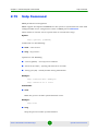
2.13
Sflowagent (Sflow Agent)
Sflowagent (Sflow Agent)
Sflow Agent is a realization of a standard STP protocol agent.
Syntax:
Available commands are:
sta[rt] Start Sflow agent
sto[p] Stop Sflow agent
wi[pe] Stop Sflow agent and clean all configuration
add[instance] 'name' Add instance (default 'ipstat')
del[instance] 'name' Delete instance (default 'ipstat')
stat 'name' Show statistics for instance (default 'ipstat')
cl[earstat] 'name' Clear statistics for instance (default
'ipstat')
Available options are:
-collector=IPaddress[:port] Set collector address
-agent=IPaddress Set agent address (default 0.0.0.0)
-maxpacket=size Set maximal datagram size (default 1500)
-interval=number Set statistics receive interval, in seconds
(default 5)
-datagrams=number Set datagrams per statistics interval
(default 100)
-rawheader={on|off} Sends original ipV4 headers (default off)
-debug={on|off} Puts debug output to log (default off)
-version -v Display Version
Description:
Sflow - protocol for monitoring computer networks. It is commonly used by
Internet Providers to capture traffic data in switched or routed networks.
Sflowagent command allows configuration of Sflow agent on the device.
sflow sta[rt] - starts Sflow agent
sflow sto[p] - stops Sflow agent
Alvarion BreezeNET B130/B300 GigE
25
Operational User Manual
Chapter 2 - General Purpose Command Set
Sflowagent (Sflow Agent)
sflow wi[pe] - stops Sflow agent and clears its configuration
sflow add[instance] 'name' - adds statistics gathering component (if 'name'
parameter is not specified then 'ipstat' component will be used)
sflow del[instance] 'name' - deletes statistics gathering component (if 'name'
parameter is not specified then 'ipstat' component will be used)
sflow stat 'name' - shows statistics for a component (if 'name' parameter is
not specified then 'ipstat' component will be used)
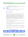
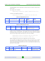
Command output:
Parameter
Description
Total flow records
Number or records delivered from Instance.
Total flow samples
Number of grouped records delivered from flow records.
Overflow records
Number of records in Instance for all cases when
Instance overflowed earlier then interval period had
ended.
Overflow count
Number of times when Instance overflowed earlier then
interval period had ended.
Total cycles
Overall number of gathering statistics success cycles.
Total datagrams
Overall number of sent datagrams.
Unused datagrams
Number of datagrams that could be created in compliance with datagrams parameter but was not used.
Bytes sent
Overall number of transmitted data by Sflow protocol.
Lost flow samples
Number of flow samples that were discarded because of
maxpacket, interval and datagrams parameters low values.
Lost flow records
Number of flow records that were discarded because of
maxpacket, interval and datagrams parameters low values.
Lost overflow
records
Number of times when Instance overflowed earlier than
the interval period ended and data were lost.
sflow cl[earstat] 'name' - clears statistics for a component (if 'name'
parameter is not specified then 'ipstat' component will be used)
sflow collector=IPaddress[:port] - sets address of a collector that process
sflow-packets. Default port is 6343.
Alvarion BreezeNET B130/B300 GigE
26
Operational User Manual
Chapter 2 - General Purpose Command Set
Sflowagent (Sflow Agent)
flow -agent=IPaddress - sets agent's own address (device)
sflow -maxpacket=size - sets maximum size of a Sflow-packet in bytes. 1472
bytes by default. Upper bound is limited by hardware and operational system
capabilities. In case of its exceeding packet size will be decreased to acceptable
value.
sflow -interval=number - time in seconds equal to interval with which
statistics is delivered from instance. Increasing of this parameter leads to
increasing in overall system efficiency but in case of unexpected network
activity splash data could be lost. 15 seconds by default.
sflow -datagrams=number - maximum number of datagrams between times
of receiving statistics from instance. The increase of this parameter leads to
the decrease in datagram average size and increases in theoretical number of
delivered statistics data. Reduces the load on the CPU but in the same time
reduces overall system efficiency. However, reducing of system efficiency
doesn't happen with low traffic. It is recommended to increase this parameter
when decreasing maxpacket parameter and/or when increasing interval
parameter. 100 by default. Maximum flow: sflow= datagrams/interval*
maxpacket, (Bytes/sec).
sflow -rawheader={on|off} - sends original ipV4 headers in spite of statistics
data (off by default). Used for compliance with traffic monitoring programs.
Sflow -debug={on|off} - puts statistics information to log.
Example:
ipstat enable full detail 3000 # starting the process of
gathering statistics
sflow add ipstat # adding gathering component
sflow -collector=1.2.3.4 start # starting process of
processing the statistics
Alvarion BreezeNET B130/B300 GigE
27
Operational User Manual
Chapter 2 - General Purpose Command Set
2.14
Acl Command (Access Control Lists)
Acl Command (Access Control Lists)
Access Control Lists.
Syntax:
acl add $NAME TYPE params...
acl del $NAME [params...]
acl ren $NAME1 $NAME2
acl flush
Possible TYPES:
net num
Predefined ACL names:
$ACLOCAL - Hosts (networks) permitted to configure the
device.
Command description
While network planning you may often need to group similar parameters in lists
which can be used for different filters (e.g. ipfw, qm, ipstat). Access control lists
(ACL) can effectively solve this problem.
acl add command creates an access list of NAME title and TYPE type. Lists names
MUST start with $ symbol and can include up to 7 letters, digits and other
symbols excluding spaces and semicolon. At the same time the command can
contain several parameters of TYPE type which will be included in the list. If the
list with this name has been already created listed parameters will be attached to
this list.
acl del command deletes specified parameters from the NAME list. If none of
parameters are mentioned all list will be deleted.
acl rename command changes list's name from NAME1 to NAME2.
acl flush command deletes all lists
Accepted list types (TYPE):
net - contains network addresses in dot format.
xxx.xxx.xxx.xxx or xxx.xxx.xxx.xxx/MASK_LENGTH or
xxx.xxx.xxx.xxx/xxx.xxx.xxx.xxx
Alvarion BreezeNET B130/B300 GigE
28
Operational User Manual
Chapter 2 - General Purpose Command Set
Acl Command (Access Control Lists)
Lists of net type optimize their parameters by excluding duplicates and by having
the feature that enables bigger networks include smaller networks. For example, if
the list contained 1.1.1.1 parameter, when you include 1.1.1.0/24 parameter in
the list 1.1.1.1 will be excluded.
Example:
acl add $LIST1 net 10.0.0.0/8 192.168.0.0/16 5.5.5.5
acl del $LIST1 5.5.5.5
Reserved access lists:
$ACLOCAL - reserved list for access limitation to the device via telnet, ftp and
http protocols. Having "$ACLOCAL" access list in the configuration all attempts to
establish a connection with the device from addresses (networks) that are not in
this list will be rejected.
Example:
acl add $ACLOCAL net 10.0.0.0/8 192.168.0.0/16
Alvarion BreezeNET B130/B300 GigE
29
Operational User Manual
Chapter 2 - General Purpose Command Set
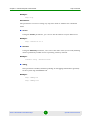
2.15
Sntp Command
Sntp Command
SNTP parameters management.
SNTP support developed in WANFleX lets the system to synchronize the time with
configured NTP server using fourth version of SNTP protocol RFC 2030.
Client works in unicast server request mode in certain time range.
Syntax:
sntp [options] [command]
Commands are the following:
start - start service
stop - stop service
Options are the following:
-server={ipaddr} - set sntp server address
-interval={seconds} - specify poll interval in seconds
-debug={on|off} - enable/disable debug information
Example:
sntp -interval=3600 -debug=on
sntp -server=9.1.1.1 start
Commands:
start
Make the process of time synchronization active.
Example:
sntp start
stop
Stop the process of time synchronization.
Alvarion BreezeNET B130/B300 GigE
30
Operational User Manual
Chapter 2 - General Purpose Command Set
Sntp Command
Example:
sntp stop
Parameters:
The parameters can be set using any sequence with or without the command
itself.
server
Using the server parameter, you can set the IP-address of your NTP server.
Example:
sntp -server=9.1.1.1
interval
Using the interval parameter, one can set the time value (in seconds) defining
client's periodicity of NTP server requesting. 3600 by default.
Example:
console> sntp -interval=5000
debug
This parameter enables/disables printing of debugging information (packets)
in the system log of WANFleX OS.
Example:
sntp -debug=on
sntp -debug=off
Alvarion BreezeNET B130/B300 GigE
31
Operational User Manual
Chapter 2 - General Purpose Command Set
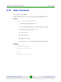
2.16
Date Command
Date Command
Date and time management.
This command shows or sets the date and time in WANFleX system.
Syntax:
date [[[[[cc]yy]mm]dd]HH]MM[.ss]]
cc - Century (is added before Year)
yy - Year in abbreviated form (i.e. 89 for 1989, 05 for 2005)
mm - Month in numeric form (1 to 12)
dd - Day (1 to 31)
HH - Hour (0 to 23)
MM - Minute (0 to 59)
ss - Second (0 to 61 - 59 plus maximum two leap seconds)
Example:
date 200402100530.04
Tue Feb 10 05:30:04 2004
date
Tue Feb 10 05:30:10 2004
Alvarion BreezeNET B130/B300 GigE
32
Operational User Manual
Chapter 2 - General Purpose Command Set
2.17
License Command
License Command
This command manages operations with a license file on the device.
Syntax:
license [options]
Options are:
--install=<url> - install new license
--export=<url>
- export current license to external server
--show
- show license info
<url> = ftp://[login[:password]@]host/file
Description:
Install option uploads license file into the device from a remote server using FTP.
Export option downloads license file from the device to a remote server using FTP.
Show option displays license information on the screen.
File-name is the name of the file containing the information transferred. The file
name shall be specified in full, in the format of the remote server's file system.
IP-address is the IP_address of the remote server.
Examples:
li
--export=ftp://ftp_login:[email protected]/licens
e_file
li -show
Alvarion BreezeNET B130/B300 GigE
33
Operational User Manual
Chapter 2 - General Purpose Command Set
2.18
Dport Command
Dport Command
Syntax:
dport BAUD
Description:
This command sets a bitrate of the console port. Available values are: 9600,
19200, 38400, 57600, 115200 Bit/sec. Default value is 38400 Bit/sec.
Alvarion BreezeNET B130/B300 GigE
34
Operational User Manual
Chapter 2 - General Purpose Command Set
2.19
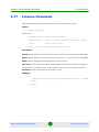
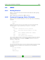
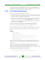
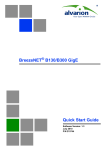
Mem Command
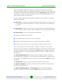
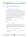
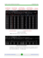
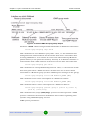
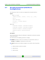
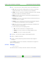
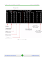
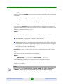
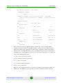
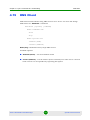
Mem Command
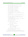
Syntax:
mem
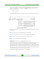
Description:
This command show statistics for allocated device memory, network buffers,
queues and drops on interfaces. Command output is described in the picture
below.
Figure 2-1: Mem Command
Alvarion BreezeNET B130/B300 GigE
35
Operational User Manual
Chapter
3
Layer 2 Command Set - PHY and
MAC
Chapter 3 - Layer 2 Command Set - PHY and MAC
In This Chapter:
“Rfconfig Command (Radio Interface Configuration)” on page 38
“MINT (“mint” command)” on page 42
“Ltest (Radio Link Test)” on page 61
“Muffer Command (Environment Analyzer)” on page 66
“Arp Command (ARP Protocol)” on page 74
“Macf Command (Addresses Mapping)” on page 76
“Switch Command” on page 79
“Dfs (Dynamic Frequency Selection)” on page 99
Alvarion BreezeNET B130/B300 GigE
37
Operational User Manual
Chapter 3 - Layer 2 Command Set - PHY and MAC
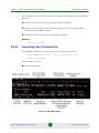
3.1
Rfconfig Command (Radio Interface Configuration)
Rfconfig Command (Radio Interface
Configuration)
The command is used to configure a radio module.
Syntax:
rf interface parameters...
Interface rf5.0 parameters:
band XXX: bandwidth (MHz) - {double (40)|full (20)|half
(10)|quarter (5)}
freq
XXX:
central frequency
bitr
XXX:
bitrate (Kbps)
sid
XXX:
system identifier - up to 8 hex digits.
txpwr XXX: tx power (dBm)
[-]pwrctl :
automatic TPC mode
[noise XXX]
where Commands:
rfconfig IFNAME capabilities
rfconfig IFNAME statistics
Options description:
Sets parameters of a radio module specified by the IFNAME (name of the radio
interface) parameter, or displays them if executed without any optional
parameter. Optional parameters are as follows:
band XXX: this option allows choosing the channel width for transmitting.
Double means 40 MHz, Full - 20 MHz, half - 10 MHz, quarter - 5 MHz. Units
in one PTP connection must have the same channel width. Example:
rf rf5.0 band half
Alvarion BreezeNET B130/B300 GigE
38
Operational User Manual
Chapter 3 - Layer 2 Command Set - PHY and MAC
Rfconfig Command (Radio Interface Configuration)
bitr XXX: the bit transfer rate (in Kbit/s) of the radio link. Allowed values
depend on selected channel width:
»
5 MHz: 3250, 6500, 9750, 13000, 19500, 26000, 29250, 32500 Kbit/s
»
10 MHz: 6500, 13000, 19500, 26000, 39000, 52000, 58500, 65000 Kbit/s
»
20 MHz: 13000, 26000, 39000, 52000, 78000, 104000, 117000, 130000
Kbit/s
»
40 MHz: 30000, 60000, 90000, 120000, 180000, 240000, 270000,
300000 Kbit/s
Freq XXX: the radio link frequency (in MHz).
The list of allowed frequencies can be obtained by executing "rf if-name cap"
command.
Sid XXX: system identifier of the device, a hexadecimal number in the range of
1H to FFFFFFH. All devices that are supposed to see each other on the same
radio link must have the same identifier.
txpwr: sets the emitting power of the transmitter (in dBm).The acceptable
transmit power values can vary depending on the type of the radio module
installed. The acceptable transmit power values can be viewed by using the "rf
<if-name> capabilities" command.
CAUTION
The entered txpwr value is rounded to the most near x.5 multiple value (for example: 17.6dBm is
rounded to 17.5dBm; 17.8dBm to 18dBm; 17.4dBm to 17.5dBm).
"[-]pwrctl" option enables ATPC (automatic transmit power control) function
on the device interface. When it is enabled (rf rf5.0 txpwr <power> pwrctl) the
system will maintain the lowest possible (optimal) power level necessary to
achieve maximum productivity.
noise sets Noise Floor Threshold for radio interface. Measured in decibel. By
default Noise Floor Threshold is 20 dB. Noise Floor Threshold is defined as a
positive shift relative to the current level of noise which is measured by a
device (Noise floor Threshold cannot be set to 0). The unit begins data
transmission only when there are no signals in the air that have signal level
Alvarion BreezeNET B130/B300 GigE
39
Operational User Manual
Chapter 3 - Layer 2 Command Set - PHY and MAC
Rfconfig Command (Radio Interface Configuration)
higher than Noise Floor Threshold. See Noise Floor and Noise floor Threshold
values with "rf IFNAME stat" command.
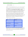
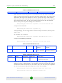
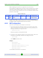
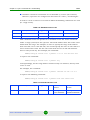
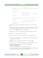
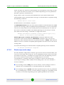
Commands Description:
statistics: displays current values of the radio module's statistics with 1 sec
interval.
The table below shows the "rfconfig stat" command output:
Table 3-1: “rf stat” output for 5GHz devices
Parameter
Description
Broadcast rate
Current bitrate value for Broadcast and Multicast packets
Voice Mode
ON/OFF value. If turned ON, the mode of their prioritized processing
is turned on
Bytes Received
Number of received bytes including headers
Bytes Transmitted
Number of transmitted bytes including headers
Packets Received OK
Number of correctly received packets
Packets Transmitted OK
Number of correctly transmitted packets
Duplicate Received
Number of duplicate packets received due to protocol excesses
Aggr duplicates
Number of duplicate aggregates received
Aggr drops
Number of packet drops in an aggregate due to protocol excesses
(in receiving)
Total Retries
Total number of retries
FIFO Overrun
Number of FIFO queues overruns in the radio when receiving
FIFO Underrun
Number of FIFO queues underruns in the radio while transmitting
CRC Errors
Number of received packets with CRC errors
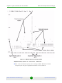
Excessive Retries
Number of packets which were not transmitted with maximal number
of retries
Noise Floor
Input noise level. Measurement cycle -10 seconds
Noise Floor Threshold
Noise Floor Threshold for Carrier Detect
Decrypted frames
Number of successfully decrypted packets
Decrypted errors
Number of errors in the decryption process
Replay drops
Number of packet drops in an aggregate due to the packet sequence
errors
Alvarion BreezeNET B130/B300 GigE
40
Operational User Manual
Chapter 3 - Layer 2 Command Set - PHY and MAC
Rfconfig Command (Radio Interface Configuration)
Table 3-1: “rf stat” output for 5GHz devices
Parameter
Description
Aggr Subframe Retries
Number of packet drops in an aggregate due to protocol excesses
(for transmission)
Aggr Full Retries
Number of duplicate aggregates transmitted
Max aggr frames
Maximal detected number of packets in an aggregate
Max aggr bytes
Maximal detected bytes in an aggregate
Encrypted frames
Number of successfully encrypted packets
capabilities: displays the radio module's internal information on its operating
features including acceptable transmit power levels, frequencies etc.
Examples:
rfconfig rf5.0 sid 1 bitr 130000 freq 5725
rfconfig rf5.0 bitr 39000 freq 5280 sid 01020304
rfconfig rf5.0 txpwr 18
Alvarion BreezeNET B130/B300 GigE
41
Operational User Manual
Chapter 3 - Layer 2 Command Set - PHY and MAC
MINT (“mint” command)
3.2
MINT (“mint” command)
3.2.1
General Description
MINT - Microwave Interconnection NeTworks - architecture gives a
functionality to present a radio interface of a unit (as well as a network connected
to it) as a traditional Ethernet in a bus topology. Therefore the unit can have
several Ethernet interfaces and several pseudo-interfaces (tun, ppp, null etc). Any
of Ethernet interfaces can be united in bridging groups which consist of two or
more interfaces. Moreover, routing mode can also be used.
Full syntax:
mint IFNAME -type {master | slave}
mint IFNAME -mode {mobile | nomadic | fixed}
mint IFNAME -nodeid NUMBERID
mint IFNAME -name NAME
mint IFNAME -key SECRETKEY
mint IFNAME -authmode {public | static | remote}
mint IFNAME -[no]authrelay
mint IFNAME -[no]snmprelay
mint IFNAME -[no]autobitrate [+/-DB] | -fixedbitrate
mint IFNAME -minbitrate XX
mint IFNAME [-loamp XX] [-hiamp XX]
mint IFNAME -[no]crypt
mint IFNAME -airupdate {disable | {[active | passive]|force}}
[fast|normal|slow]
mint IFNAME -[no]log [detail]
mint IFNAME roaming {leader | enable}
mint IFNAME profile N [-freq X[,Y,N-M,,..] | auto] [-sid
X[,Y,..]] [-bitr X]
[-band {double | full | half | quarter}]
[-type {master|slave}] [-key XXX] [-nodeid N]
[{-minbitr XXX [-autobitr [+/-dB]] | -fixedbitr}]
[enable | disable | delete]
Alvarion BreezeNET B130/B300 GigE
42
Operational User Manual
Chapter 3 - Layer 2 Command Set - PHY and MAC
MINT (“mint” command)
mint IFNAME addnode -mac X:X:X:X:X:X [-key STRING] [-note
STRING]
[-maxrate XX]
[-lip X.X.X.X] [-tip X.X.X.X] [-mask X.X.X.X]
[-lgw X.X.X.X] [-tgw {X.X.X.X | none}]
[-lcost XX] [-tcost XX] [{-setpri | -addpri} NN
| -1]
[-disable | -enable | -delete]
mint IFNAME addnode [-defgw X.X.X.X] [-defmask X.X.X.X]
mint IFNAME delnode -mac X:X:X:X:X:X
mint IFNAME map [routes | full | swg] [detail] [-m]
mint IFNAME monitor [-s] [-i SEC] [MAC [MAC ...]]
mint IFNAME rcmd -node {ADDR|all} [-peer][-self] {-cmd "CMD"
| -file URL} [-key KEY] [-quiet]
mint IFNAME -rcmdserver {disable | enable} -guestKey STRING
-fullKey STRING
mint -[no]colormap
mint IFNAME start | stop | restart | clear
mint IFNAME poll {start [log] | stop | stat [clear]}
mint vers
3.2.2
General Commands Description
3.2.2.1
Setting the Node Type
Syntax:
mint IFNAME -type {master | slave}
The command sets the type of node.
Two node types are available:
MASTER:
Master can establish connections with slave node.
On master node a marker access (polling) can be enabled.
Alvarion BreezeNET B130/B300 GigE
43
Operational User Manual
Chapter 3 - Layer 2 Command Set - PHY and MAC
MINT (“mint” command)
SLAVE:
Can connect to the node with master type. When connection is lost, the device
attempts to restore the connection to the master node.
NOTE
When the node's type is switched to slave the following configuration changes are performed
automatically: the "roaming enable" mode is enabled and a roaming profile is created with current
rf5.0 settings.
When the node's type is switched to master the "roaming leader" mode is enabled automatically.
Example:
mint rf5.0 -type master
3.2.2.2
Setting the Node Mode
Syntax:
mint IFNAME -mode {mobile | nomadic | fixed}
The command sets the mode of the node. The mode is defined by the application
of the node for the network. Modes description:
Fixed. The network node has a fixed allocation and never moves and never is
switched off. This is a infrastructure node of the network
Nomadic. Node may change its physical allocation but all the data
transmitting is made when the node is not moving (or moving very slowly)
Mobile. The node may move and exchange data while moving
Example:
mint rf5.0 -mode nomadic
3.2.2.3
Setting Node Sequential Number
Syntax:
mint IFNAME -nodeid NUMBERID
The command sets the sequential number for the node. The parameter is optional.
Two units with the same ID can make a link.
Example:
mint rf5.0 -nodeid 5
Alvarion BreezeNET B130/B300 GigE
44
Operational User Manual
Chapter 3 - Layer 2 Command Set - PHY and MAC
3.2.2.4
MINT (“mint” command)
Setting Node Name
Syntax:
mint IFNAME -name NAME
The command sets the name for the node. Node name will be displayed in
"mint map" set of commands. Node name should not exceed 16 characters.
Spaces in the node name are accepted if put between quotation marks.
Example:
mint rf5.0 -name My_node
mint rf5.0 -name "Master Unit"
3.2.2.5
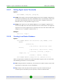
Switching to Marker Access Mode (Polling)
Syntax:
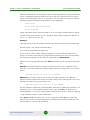
mint IFNAME poll {start [log] | stop}
The command turns on/off polling mode for the master station.
Polling mode is a method of accessing common radio channel under master
station control. Master station manages both its own and slave's transmission
sessions, so that they can avoid mutual collisions in the radio channel.
The polling mode is enabled on the master station only. Configuration of slave
unit needs not to be modified.
For fine tuning of polling regime there are three optional parameters which can be
set using the following syntax:
mint IFname poll start [mi=XX] [ub=XX] [mt=XX]
MI - Marker Interval. The primary time unit used in calculating the marker
sending frequency. The approximate value is a half of the round-trip delay for
the interface. Values are given in milliseconds, starting from 41 ms.
UB - Upper bound. Marker sending interval upper bound. This value provides
a minimal guaranteed marker sending frequency. This parameter is chosen
based on the compromise between the total number of markers loading up the
channel for no purpose and the response time for the first key pressed in
telnet program. The value is within 3 and 1000 ms. 70 ms by default.
MT - Marker Timeout. The maximum waiting time for a client unit response to
a marker or data packet. Expressed in milliseconds; default value is 12 ms.
Alvarion BreezeNET B130/B300 GigE
45
Operational User Manual
Chapter 3 - Layer 2 Command Set - PHY and MAC
MINT (“mint” command)
Example:
mint rf5.0 poll start ub=250
3.2.2.6
Switching to Automatic Bitrate Control Mode
Syntax:
mint IFNAME -[no]autobitrate [+/-DB]
Enables/disables an automatic speed management mode.
In autobitrate mode every device controls the connection parameters
independently (amplitude of the received signal, number of ARQs on transmitting,
errors, SNR on the opposite side etc) and chooses such transmitting speed which
provides necessary conditions for a reliable work with minimum number of ARQs
and losses. Speed values can be different for each direction but it will be optimal.
When no autobitrate is used transmitting speed will be set according to the setting
of "bitr" parameter of "rfconfig" command. When autobitrate is used, transmitting
speed will be automatically adjusted according to current link conditions. The
ranges of speed will be in between the setting of "bitr" parameter in "rfconfig"
command (maximal speed) and "minbitrate" parameter (see below). If no
"minbitrate" is specified the minimal RF interface speed will be taken as a lowest
possible transmitting speed.
Minimal transmitting speed for autobitrate mode can be set with a help of the
following command:
mint IFNAME -minbitrate BITRATE
Example:
mint rf5.0 -autobitrate
mint rf5.0 -minbitrate 9000
+/-DB option influences the autobitrate function sensitivity. Autobitrate can be
forced to set a higher bitrate (mint IFNAME -autobitrate - <number in dB>) even if
the signal level is lower than expected on the specified number of dB. Or not to set
a higher bitrate (mint IFNAME -autobitrate + <number in dB>) till the signal level
won't become higher than expected on the specified number of dB. The default
value is "-6".
To disable the autobitrate mode the following command is used:
mint rf5.0 -fixedbitrate
In the fixedbitrate mode the actual bitrate is set with the "bitr" parameter of the
"rfconfig" command.
Alvarion BreezeNET B130/B300 GigE
46
Operational User Manual
Chapter 3 - Layer 2 Command Set - PHY and MAC
3.2.2.7
MINT (“mint” command)
Setting Signal Levels Thresholds
Syntax:
mint IFNAME [-loamp XX] [-hiamp XX]
loamp. This option sets the minimal signal level for the neighbor. Signal level
is measured in dB above the noise threshold for the current bitrate. If the level
gets lower than specified value the connection with a neighbor will be lost.
Default value is 2. The possible range is 0 to 6.
hiamp. This option sets the minimal SNR for a new neighbor. Signal level is
measured in dB above the noise threshold for the current bitrate. If neighbor's
signal level is equal or higher than a specified value the node will consider this
neighbor to be a candidate. Default value - 6
Example:
mint rf5.0 -loamp 2
3.2.2.8
Creating Local Nodes Database
Syntax:
mint IFNAME addnode -mac X:X:X:X:X:X [-key STRING] [-note
STRING]
[-maxrate XX]
[-lip X.X.X.X] [-tip X.X.X.X] [-mask
X.X.X.X]
[-lgw X.X.X.X] [-tgw {X.X.X.X | none}]
[-lcost XX] [-tcost XX] [{-setpri |
-addpri} NN | -1]
[-disable | -enable | -delete]
mint IFNAME addnode [-defgw X.X.X.X] [-defmask X.X.X.X]
This set of parameters defines the nodes with which a given node can work with.
The following parameters can be specified:
mac. This parameter is mandatory. X:X:X:X:X:X is a MAC-address of the node
with which a connection can be established.
key. Unique unit's key (key word or phrase up to 64 characters long; if
contains spaces should be put into quotes). Used in authentication
Alvarion BreezeNET B130/B300 GigE
47
Operational User Manual
Chapter 3 - Layer 2 Command Set - PHY and MAC
MINT (“mint” command)
procedures. The same key should be specified in the settings of the connecting
unit ("mint IFNAME -key").
lip. Local IP-address. This address will be assigned to this unit when the
connection with a remote is established
tip and mask. Target IP-address and mask. This address will be assigned to
the remote side when a connection is established. The mask is applied to both
Local IP and Target IP. If mask is not specified these addresses will not be used
lgw. Local gateway IP-address (will be assigned to the local node once
connection is established)
tgw. Target gateway IP-address (will be assigned to the remote node once
connection is established). None option forbids providing information about
default gateway (that is set by "addnode -defgw" command) to the remote node.
lcost. Local cost of the connection to this neighbor from current node. If not
specified, MINT will automatically calculate the cost
tcost. Target cost of the connection from this neighbor to the current node. If
not specified, MINT will automatically calculate the cost. If lcost and tcost
parameters are set on a pair of neighbors, lcost has a higher priority.
enable/disable/delete. Self-explanatory - enables, disables or deletes a
record in a local database.
maxrate. Target node maximum bitrate in kilobit per second.
setpri | addpri. This options allows setting/increasing the priority of packets
passing through to the specified node. "Setpri" parameter is used to change a
priority to the value specified in the command. When using "-1" value a
package priority is dropped to the lowest priority. "Addpri" is used to change a
priority only in case it is higher than the previous one (Note: the smaller is the
value the higher is the priority). So you can only increase priority using
"addpri" parameter.
note. This option allows making some word note (description) for the specified
node.
Example:
Alvarion BreezeNET B130/B300 GigE
48
Operational User Manual
Chapter 3 - Layer 2 Command Set - PHY and MAC
MINT (“mint” command)
mint rf5.0 addnode -mac 000028BAF234 -lip 1.1.1.1 -tip
1.1.1.2 -mask 255.255.255.252 -lcost 120
For easy nodes definition in the local database "mint addnode" command is
updated with two options: "-defgw X.X.X.X" "-defmask X.X.X.X".
-defgw X.X.X.X. Sets default gateway.
-defmask X.X.X.X. Set default mask.
When mask or gateway values are not defined for the defining node then default
gateway or default mask will be used for this node. In this case, to add a node to
the local database it is enough to define MAC-address (mac), target IP-address
(tip) and a secret key:
mint rf4.0 addnode -mac 000435567322 -tip 10.1.1.1 -key
SecretKey1
If a key is not specified for a defining node then the key of the host node is
assigned.
NOTE
Information about default gateway (that is set by "addnode -tgw / addnode -defgw" commands) is
not provided to a defining node in case IP-address and network mask is not specified.
3.2.2.9
Deleting a Node From Local Database
Syntax:
mint IFNAME delnode -mac X:X:X:X:X:X
The command deletes a record created using "addnode" command with a
corresponding MAC-address.
Example:
mint rf5.0 delnode -mac 000028BAF234
3.2.2.10
Managing MINT Protocol
Syntax:
mint rf5.0 start | stop | restart
The command starts, stops, restarts MINT protocol or clears (deletes) MINT
configuration.
Example:
Alvarion BreezeNET B130/B300 GigE
49
Operational User Manual
Chapter 3 - Layer 2 Command Set - PHY and MAC
MINT (“mint” command)
mint rf5.0 start
The following command resets the MINT configuration to default and stops the
transmission:
mint rf5.0 clear
To make the unit transmit again it is necessary to enter "mint rf5.0 start".
3.2.2.11
MINT Log Settings
The following command is used to control log settings for MINT protocol:
mint IFNAME -[no]log [detail]
Three different modes are available:
No logging. "-nolog" option is used
Limited logging. "-log" option is used. The messages on
connecting/disconnecting neighbors will be put to the system log
Detailed logging. "-log detail" option is used. Along with the messages from
limited logging mode, messages on changing costs of the routes and changing
bitrates (in autobitrate) mode will be put to the system log
Example:
mint rf5.0 -log detail
This command will turn full logging on.
3.2.2.12
MINT Protocol Version
Syntax:
mint vers
The command shows current version of MINT protocol.
3.2.3
Nodes Authentication
Setting the secret key:
mint IFNAME -key SECRETKEY
This command sets the secret key for the current node. See different
authentication modes descriptions below to learn how it is being used. The key
can be up to 64 characters long and should not contain spaces (or should be put
in quotes).
Alvarion BreezeNET B130/B300 GigE
50
Operational User Manual
Chapter 3 - Layer 2 Command Set - PHY and MAC
MINT (“mint” command)
mint IFNAME -authmode {public | static | remote}
The command sets the type of nodes authentication.
There are three types of nodes authentication available:
public - all nodes have the same key (password) for access. The simplest case
of authentication. It can be used for small workgroups, point-to-point
connections, mass public access networks and for MINT architecture testing
purposes. Any two nodes of the network can establish a connection (given
other settings are suitable) if their keys are equal. In public mode, having
found a potential neighbor a node check for its information in the local
database (defined by "mint IFNAME addnode" commands). If requested
information is found, a key from a local database will be used. Otherwise, it is
assumed that neighbor's key corresponds with node's own key ("mint IFNAME
-key" parameter)
static - every node has a full list of nodes (including their parameters and
access keys) with which a connection can be established. This mode is suitable
for an autonomous area of service with no need of centralized management
and monitoring. Obviously, nodes that are included in each others access lists
(local databases) should have a physical ability to connect to each other in
order to establish a connection. In static mode each node must have a list of
all permitted neighbors in a local database formed by a set of "mint IFNAME
addnode" commands. If no information on the neighbor is found in the
database the connection is being rejected.
remote - centralized authentication mode with remote. In this mode any node
can request the information from a remote authentication server. This means
that the node must have an access to this server (e.g. using IP).
A node having a local database of its neighbors or having an access to a remote
authentication server can be configured as an authentication relay. For this
purpose the following command is used:
mint IFNAME
-[no]authrelay
The information about authentication relay will be automatically distributed
throughout the MINT network. Nodes which use remote mode of authentication
but both do not have access to the remote server and do not have the information
in their local database will use authentication relay in order to obtain the keys of
potential neighbors.
mint IFNAME
Alvarion BreezeNET B130/B300 GigE
-[no]snmprelay
51
Operational User Manual
Chapter 3 - Layer 2 Command Set - PHY and MAC
MINT (“mint” command)
The information about SNMP relay will be automatically distributed throughout
the MINT network. Nodes will use remote SNMP services.
Example 1:
Nodes A and B use the same key and can establish a connection with each other
in public authentication mode.
Node A:
mint rf5.0 -key SECRETKEY
mint rf5.0 -authmode public
Node B:
mint rf5.0 -key SECRETKEY
mint rf5.0 -authmode public
Example 2:
Nodes A and B have different keys but they can establish a connection with each
other using their local databases.
Node A:
mint rf5.0 -key SECRETKEY
mint rf5.0 -authmode public
mint rf5.0 addnode -mac B:B:B:B:B:B -key KEY2
Node B:
mint rf5.0 -key KEY2
mint rf5.0 -authmode public
mint rf5.0 addnode -mac A:A:A:A:A:A -key SECRETKEY
Moreover, each of these two nodes can set up connections with other nodes
working in public mode if their keys correspond with each other.
Example 3:
Node A has a local database and acts as an authentication relay. Node B does not
have a database and uses a relay in remote mode
Node A:
mint rf5.0 -key KEY1
mint rf5.0 -authmode static
Alvarion BreezeNET B130/B300 GigE
52
Operational User Manual
Chapter 3 - Layer 2 Command Set - PHY and MAC
MINT (“mint” command)
mint rf5.0 -authrelay
mint rf5.0 addnode -mac B:B:B:B:B:B -key KEY2
mint rf5.0 addnode -mac A:A:A:A:A:A -key KEY3
Node B:
mint rf5.0 -key KEY2
mint rf5.0 -authmode remote
Node B will be getting neighbors' information via relay (Node A).
If Node A is switched to remote mode and there is no information in the local
database, the authentication request will be forwarded to the remote server (if
specified and accessible) or to another authentication relay.
3.2.4
Automatic Over-the-Air Firmware Upgrade
mint IFNAME -airupdate {disable | {[active | passive]|force}}
[fast|normal|slow]
This set of commands manages the Automatic Over-the-air Firmware Update
system.
3.2.4.1
What is it?
The AirUpdate system provides with an easier ways of massive firmware upgrade
in the MINT network for a big number of the nodes (same type). In order to do that
only one unit of each type should be manually (or through the scheduler)
upgraded - other units will get new firmware automatically.
3.2.4.2
How does it work?
Every unit can be configured for AirUpdate in passive or active mode. Active units
periodically (every 30 minutes) announce the information about their firmware to
the MINT network. The information includes the version of the firmware and the
time of uninterrupted (without reboots) work with this version. All units of MINT
network (both active and passive) receive and accumulate the information from
active units choosing the source with the latest version of firmware with which the
source has worked for the longest period of time.
After the period of information accumulation passive units send their requests for
the new firmware to the chosen source. Active units form a list of requests and
perform a group distribution of the firmware using special MINT multi-address
distribution protocol.
The period of information accumulation can be changed using fast, normal and
slow parameter of the command.
Alvarion BreezeNET B130/B300 GigE
53
Operational User Manual
Chapter 3 - Layer 2 Command Set - PHY and MAC
MINT (“mint” command)
In fast mode the unit will wait for the potential source of the firmware to work
with new version within two hours with no reboots. Only after two hours the
request will be sent.
In normal mode the waiting period is 7 hours; in slow - 24 hours
By default, passive normal mode is turned on.
For immediate firmware upgrade there is a special option “force”. The command
is not saved in the configuration and acts as a signal for all units to send their
requests for upgrade regardless the work mode and information accumulation
time period.
If during the process of new firmware distribution an error occurs (or link loss) the
passive unit will stop the upload process and will resend its request after getting
an announcement.
Examples:
The unit is in the active mode sending announcements about new firmware
version. If units with newer firmware version are found on the network, the
upload request will be sent in no less than 7 hours after uninterrupted work of the
announcement source:
mint rf5.0 -airupdate active normal
The unit is the passive mode waiting for the source of the latest firmware version
to work with it during no less than 24 hours:
mint rf5.0 -airupdate passive slow
The operator decides to immediately upgrade all the units with new firmware:
mint rf5.0 -airupdate force
The unit is not participating in AirUpdate process. It does not send
announcements and does not generate requests for upgrades:
mint rf5.0 -airupdate disable
3.2.5
Over-the-Air Encryption
All MINT protocol messages are automatically encrypted. This feature is always
turned on.
AES-128 CCMP hardware encryption is used on the device.
For full data encryption the following command is used:
mint IFNAME -[no]crypt
Alvarion BreezeNET B130/B300 GigE
54
Operational User Manual
Chapter 3 - Layer 2 Command Set - PHY and MAC
MINT (“mint” command)
The command turns on/off over-the-air encryption. Encryption has the following
features:
Each node has its own key for outgoing traffic encryption
There is no restrictions on the number of nodes that use outgoing traffic
encryption in the MINT network
Every three minutes the key is dynamically changed
Example:
mint rf5.0 -crypt
3.2.6
Learning the Connection
The following command is used to learn the state of the connection:
mint IFNAME map [routes | full | swg] [detail] [-m]
mint -[no]colormap
Three options are used:
The default output:
Figure 3-1: Mint Map Output
Alvarion BreezeNET B130/B300 GigE
55
Operational User Manual
Chapter 3 - Layer 2 Command Set - PHY and MAC
MINT (“mint” command)
Routes. The following output is displayed:
Figure 3-2: Mint Map Routes Output
Full. A combination of the above modes
Swg. This option is used when switching groups are created in MINT network.
It shows in which switching groups neighbor node is included:
Figure 3-3: Mint Map Swg Output
Parameters:
»
-detail - shows the following information for each link with a neighboring
node: distance do the neighboring node in kilometers, load on
receive/transmit in Mbps, on receive/transmit in packets per second, link
"Cost", main IP-address of the neighboring node.
»
-m - shows I/O signal levels relative to minimal receive/transmit bitrate.
(Without -m relative to current bitrates).
Mint -[no]colormap option enables/disables color indication of the command:
Alvarion BreezeNET B130/B300 GigE
56
Operational User Manual
Chapter 3 - Layer 2 Command Set - PHY and MAC
MINT (“mint” command)
Common color identifies neighbor nodes that have acceptable characteristics
of a link to the current node.
Yellow color identifies neighbor nodes that potentially may have problems
with sustainability and quality of a link to the current node. In this case link
quality can be improved through the change of certain parameters (for
example, lowering bitrates).
Yellow color with red background identifies neighbor nodes that have
unsatisfactory characteristics of a link to the current node. For example,
neighbor nodes that have low characteristics of a link on the lowest possible
bitrate or have errors are marked this way. In this case link quality can be
improved by such actions as antenna alignment, cable connectivity testing
and so on.
When neighbor nodes are marking with certain color style it is not only signal level
but also number of retries and errors are taken into consideration.
3.2.7
Continuous Signal Levels Monitoring
Syntax:
mint IFNAME monitor [-s] [-i SECONDS] [MAC [MAC ...]]
If no MAC-addresses are specified, the output of command will contain the
information about all neighbors and candidates of the current node.
Instead of MAC-addresses "nodeid" and/or "name" of the node can be specified.
The sample output of the command is presented below.
Figure 3-4: Mint Monitor Output
"-s" option keeps the output within one screen without line-by-line output
"-i SECONDS" set the interval for information output in seconds
Alvarion BreezeNET B130/B300 GigE
57
Operational User Manual
Chapter 3 - Layer 2 Command Set - PHY and MAC
3.2.8
MINT (“mint” command)
Frequency Roaming
For a flexible management of frequency resource, higher noise immunity and
throughput optimization equipment supports frequency roaming capability based
on MINT protocol.
Any node of the network can be set up as a roaming leader. Roaming leader will
define required radio frequency parameters of the wireless network. Roaming
leader also works with a fixed radio interface parameters, however its radio
parameters configuration is transmitted over the network in special packets so
other node of the network knows whether it is connected to the roaming leader.
Roaming leader also supports DFS and Radar Detection features (if a special
license is installed for selected countries).
A network node can use roaming in order to search for the roaming leader. The
search is implemented by switching between different sets of radio parameters
that are defined in profiles. Each profile contains a fixed set of radio interface
parameters which are set at each search iteration.
NOTE
Profiles of the Roaming Leader are inactive.
Profile parameters:
freq X[,Y,N-M,...] | auto - radio interface frequency or list of frequencies. Auto
keyword can be used - in this case all frequencies that the unit supports will
be used.
sid X[,Y,..] - SID of the radio interface (or list of SIDs)
bitr X - bitrate of the radio interface. Acts as a top limit for the bitrate if
autobitrate mechanism is turned on
band {double|full|half|quarter} - defines the channel width for the profile. If
profiles use different channel widths, auto mode for frequency cannot be used
type {master|slave} - node type
key XXX - secret key
nodeid N - node ID
Alvarion BreezeNET B130/B300 GigE
58
Operational User Manual
Chapter 3 - Layer 2 Command Set - PHY and MAC
MINT (“mint” command)
fixedbitr - sets fixed bitrate for the node
minbitr XXX - minimum bitrate for operation in "autobitrate" mode
autobitr [+/-dB] - operation mode with automatic bitrate control. [+/-dB]
parameter allows to manage bitrate control sensitivity.
enable | disable | delete - enables, disables or deletes the profile.
Syntax:
mint IFNAME roaming {leader | enable | disable}
mint IFNAME profile N [-freq X[,Y,N-M,...] | auto] [-sid
X[,Y,..]] [-bitr X]
[-band {double | full | half | quarter}]
[-type {master|slave}] [-key XXX] [-nodeid N]
[{-minbitr XXX [-autobitr [+/-dB]] | -fixedbitr}]
[enable | disable | delete]
Samples:
mint rf5.0 profile 1 -freq 5920 -sid ABCDE
mint rf5.0 profile 2 -freq 5960 -sid ABCDE disable
mint rf5.0 roaming enable
3.2.9
Remote Command Management
Remote command management allows one MINT node to perform commands on
one other or all MINT nodes in the network.
Options:
-rcmdserver {disable | enable} - disables/enables remote control
management mode (enable by default)
-guestKey STRING - guest key. Guest key allows to perform read only
commands on the node
-fullKey STRING - full key. Full key grants full access to the node (all
commands can be performed)
Alvarion BreezeNET B130/B300 GigE
59
Operational User Manual
Chapter 3 - Layer 2 Command Set - PHY and MAC
MINT (“mint” command)
-node {ADDR|all} - Mac-address of the destination node or access to all MINT
nodes
[-peer] - performs commands only on the nodes that are connected to the
given device directly
[-self] - performs commands also on the device itself
{-cmd "CMD" | -file URL} - command to be performed on the remote unit or
root to a command txt file by ftp
[-key KEY] - access key
[-quiet] - disables writing replies from remote devices to a system log.
Syntax:
mint IFNAME rcmd -node {ADDR|all} [-peer][-self] {-cmd "CMD"
| -file URL} [-key KEY] [-quiet]
mint IFNAME -rcmdserver {disable | enable} -guestKey STRING
-fullKey STRING
Samples:
mint rf5.0 rcmd -node all -cmd "co sh"
mint rf5.0 rcmd -node all -file
ftp_name:[email protected]/1.txt
Alvarion BreezeNET B130/B300 GigE
60
Operational User Manual
Chapter 3 - Layer 2 Command Set - PHY and MAC
3.3
Ltest (Radio Link Test)
Ltest (Radio Link Test)
Test of a radio link. It is recommended for antenna alignment when installing a
new device or for testing of existing radio link.
Syntax:
ltest IFNAME target [-r rate[,reply_rate]] [-s
packet_size[,reply_size]] [-b] [-p priority] [-align
[L[,R]]] [-evm][-tb [seconds]] [-tu [seconds]] [-load
N[m|k] [-mint]ltest -key [PASSWORD]
ltest (-disable|-enable)
Description:
IFNAME - radio interface on which testing will be performed
target - MAC-address of a target device on the other side of a tested radio link
-r rate[,reply_rate] - sets bitrates for transmitting test packets from the local
device and toward it. This parameter is optional. There are two situations
when this parameters are not configured:
»
Local device is tested with its neighboring node, i.e. we can view remote
device and tx/rx bitrate values for it in a "mint map" command output. In
this case tx/rx bitrate values from "mint map" command output are
taken for rate and reply rate parameters.
»
Local device doesn't consider remote device as a neighboring node. In this
case rate and reply rate parameters will be equal to minimal possible
bitrate of the local device for current bandwidth (for example, 13 Mbps for
20 MHz bandwidth, 6.5Mbps for 10 MHz, 3.25 Mbps for 5 MHz).
NOTE
It is possible to set all the bitrates supported by the given device model. Even ones that are not
allowed by the current license. This allows estimating the performance of the device before
upgrading to the higher bitrate.
-s packet_size[,reply_size] - establishes test packet payload size from the
local device and toward it.
-b - transmitting broadcast test packets
Alvarion BreezeNET B130/B300 GigE
61
Operational User Manual
Chapter 3 - Layer 2 Command Set - PHY and MAC
Ltest (Radio Link Test)
-p - sets priority level to "ltest" packets (from 0 to 16). No priority is set by
default.
-key [PASSWORD] - sets password for testing. If two devices have different
passwords they can't perform testing with each other
-disable|-enable - disables/enables ability to perform link test. Enable by
default
-align [L[,R]] - special "ltest" command mode for antenna alignment. It allows
aligning each antenna of the device independently. L parameter sets which
antenna will be used to transmit test frames from the local device. R
parameter sets which antenna will be used to transmit test frames from the
remote device from the other side of the link. If L parameter is not specified
then average signal level value between two antennas will be shown. If -r is not
specified then test can be performed even when only one antenna is attached
to each side of the link. If -r is specified then L and R parameters are ignored.
L and R parameters can have the following values: 0 - antenna with vertical
polarization, 1 - antenna with horizontal polarization.
-evm - indicates the measured input signal quality (Error Vector Magnitude).
It should be as high as possible. The recommended level is not less than 21.
All parameters (including specified by default) keep its values the same as they
were at the beginning during the whole test.
Examples:
lt rf5.0 00179AC2F3E6
This command illustrates the simplest way to start link test. "lt" command with
all parameters undefined (default parameters) starts test of a local device with a
remote device which have "00179AC2F3E6" MAC-address.
lt rf5.0 00179AC2F3E6 -r 39000
This command starts link test with rate parameter 39 Mbps. In this case reply
rate parameter will be considered the same.
"ltest" command recommendations:
When "ltest" command starts it will show you output information that contains
testing results. You can see command output below:
Alvarion BreezeNET B130/B300 GigE
62
Operational User Manual
Chapter 3 - Layer 2 Command Set - PHY and MAC
Ltest (Radio Link Test)
Figure 3-5: Ltest Output
"ltest" output when using the "-align" parameter:
Figure 3-6: Ltest Align Output
The difference of this output from the standard one is that "ant.amps" column is
used instead of "amp/max". "Ant.amps" column indicates signal levels from 0, 1
and 2 antennas divided by ":" correspondingly.
Alvarion BreezeNET B130/B300 GigE
63
Operational User Manual
Chapter 3 - Layer 2 Command Set - PHY and MAC
Ltest (Radio Link Test)
For successful radio link establishment the following factors have to be
considered:
1
It is recommended to start antenna alignment with searching maximum signal
level on a minimal possible bitrate. Afterwards automatic MINT mechanisms
will set the most appropriate bitrate if autobitrate mode will be enabled.
2
Current incoming signal level in "amp/max" columns (see "ltest" command
output) must be between 12 and 40.
When it is more than 40 it is recommended to lower amplifier power.
If maximal signal level is less than 12 it is recommended to lower bitrate or
channel width (for example, from 20MHz to 10MHz on the both sides of the
radio link).
In some cases signal level that is less then 12 may be enough for radio link
operation. In this case one has to be guided by such parameters as number of
retries, number of undelivered packets and number of undelivered acks. If the
number of undelivered packets and the number of undelivered acks is null,
the number of retries is small and all these parameters are constant in time
then the radio link, most often, will be operating properly.
3
Number of retries value in "rt%" columns must be as close to zero as possible.
4
Number of undelivered packets value in "up%" columns must be zero; if this
value is not zero then the radio link couldn't be exploit.
5
Number of undelivered acks value in "ua%" columns must be zero; if this value
is not zero then the radio link couldn't be exploit.
ALL described parameters must be observed in the both (Local and Remote)
sections of the "ltest" command output.
Radio link bandwidth test (Bandwidth meter):
Bandwidth meter is used to test the following radio link characteristics: speed in
kilobits per second, speed in packets per second, number of retries and errors.
Use the following "ltest" command options for testing:
-tu [seconds] - Unidirectional test: packets are transmitted only fro the
current side to the specified address ("target" option)
-tb [seconds] - Bidirectional test: packets are transmitted in both directions
Alvarion BreezeNET B130/B300 GigE
64
Operational User Manual
Chapter 3 - Layer 2 Command Set - PHY and MAC
Ltest (Radio Link Test)
Packet size by default - 1536 bytes (to change packet size use "-s" option).
"Seconds" parameter allows setting test period (5 seconds by default). Maximum
value is 60 seconds.
-load N[m|k] option allows setting a limit on the maximal tested channel
bandwidth. By default, N parameter is measured in Megabits per second. If k
parameter is specified then in kilobits per second (for example, 10m - 10 Mbps,
500k - 500 Kbps).
"-mint" option allows performing "real-life" testing when all the traffic and link
parameters are controlled and managed by MINT functions such as ATPC and
autobitrate (in ordinary test ATPC and autobitrate are not used). In this mode the
statistics for errors and retries is not available.
This option is available only with -tu or -tb options. When using -mint option -r
option is ignored.
"Ltest" command output in Bandwidth meter mode:
Figure 3-7: Ltest Bandwidth Output
Example:
lt rf5.0 00179AC2F3E6 -tb
This command starts bidirectional link bandwidth test of a local device with a
remote device which have "00179AC2F3E6" MAC-address.
Alvarion BreezeNET B130/B300 GigE
65
Operational User Manual
Chapter 3 - Layer 2 Command Set - PHY and MAC
3.4
Muffer Command (Environment Analyzer)
Muffer Command (Environment
Analyzer)
The muffer module is used to analyze the electromagnetic environment.
Syntax:
muffer IFNAME [-tXX] [-lXX] review [FREQ1 [FREQ2 ...]]
| { mac[2|3]|mynet|scan [MAC]}
muffer IFNAME sensor [record=SEC] [F1 [F2] [BW STEP]]
muffer IFNAME sensor [replay]
muffer stat [clear]
Description:
The muffer module makes it possible to rapidly test the electromagnetic
environment, visually estimate the efficiency of the utilization of the air links,
reveal sources of interference, and estimate their power.
Several operating regimes of the muffer module provide for different levels of
details in test results.
3.4.1
Review Mode
This regime is enabled by the review option. It makes possible to have a general
estimation of emissions and interference within specified frequency range. Up to 7
frequencies (separated by spaces) subject to analysis may be specified as
parameters [FREQ1 [FREQ2 ...]. Only two last digits of the frequency values shall
be given.
CAUTION
Normal operation of a radio module is impossible when this regime is enabled.
The "muffer" command output in "review" mode is limited by text session window size.
Example:
muffer rf5.0 review
Alvarion BreezeNET B130/B300 GigE
66
Operational User Manual
Chapter 3 - Layer 2 Command Set - PHY and MAC
Muffer Command (Environment Analyzer)
Figure 3-8: Muffer Review Mode
The picture above shows the output of the review mode.
3.4.2
MAC|MAC2|MAC3|MYNET Modes
These modes perform the efficiency of their utilization of the air link. The analysis
is carried out for all MAC-addresses at the frequency previously specified by
rfconfig command. [MAC] option allows carrying the air link analysis in
MAC|MAC2|MAC3|MYNET modes for the specified MAC-address.
The mac mode checks only data packets, while in the mac2 mode the link-level
ACK messages sent by protocol support devices are also taken into account
whenever possible. Compared to mac2 mode, mac3 mode also performs
calculation of impulse interference. It shows number of detected pulses, their
average signal level and pulses per second information.
Finally, the mynet regime performs the radio testing without disturbing radio
module's normal operation.
Example:
muffer rf5.0 mac2
The picture below shows the output for mac2 regime.
Alvarion BreezeNET B130/B300 GigE
67
Operational User Manual
Chapter 3 - Layer 2 Command Set - PHY and MAC
Muffer Command (Environment Analyzer)
Figure 3-9: Muffer MAC2 Mode
3.4.3
Scan Mode
The scanning regime is enabled by a muf scan command, and provides for deep
analysis of radio emission sources within the given network's territory. In this
regime, the device scans the radio spectrum on all frequencies and for all
modulation types. [MAC] option allows carrying the air link analysis for the
specified MAC-address.
Information is displayed on any source of irregular (non-repetitive) radio signals.
To obtain information as complete as possible, the scanning process may take
significant time.
CAUTION
Normal operation of the radio module is impossible when the scan regime is enabled.
Example:
muffer rf5.0 scan
Alvarion BreezeNET B130/B300 GigE
68
Operational User Manual
Chapter 3 - Layer 2 Command Set - PHY and MAC
Muffer Command (Environment Analyzer)
Figure 3-10: Muffer Scan Mode
Supplementary options for all the above regimes:
-tXX specifies the duration of time, in seconds, for which the test regime is
enabled (2 minutes by default). The value 0 in this field enables a test regime
for unlimited time.
-lXX specifies the number of lines on the screen for displaying test results (24
lines by default)
To terminate the analyzer operation in any of the above regimes, press <ESC> or
<Ctrl/C>.
3.4.4
Statistics Module
The statistics gathering is used for estimating link load intensity. The amount of
packets sent and received, and the number of retransmissions is shown for each
MAC-address participating in the data exchange.
The statistics output is presented in the picture below.
Alvarion BreezeNET B130/B300 GigE
69
Operational User Manual
Chapter 3 - Layer 2 Command Set - PHY and MAC
Muffer Command (Environment Analyzer)
Figure 3-11: Muffer Statistics Module
The following decisions can be made by analyzing the outputted parameters:
If the number of repeated packets is comparable with total number of packets
that means that you might have an interference source on the selected
frequency. For normally operating link the percentage of repeated packets
should not exceed 10%. It is extremely important to obtain a permanent zero
value for the average number of repeats per packet. If the value is not zero that
means that the link is NOT working properly and requires further
improvement
If total percentage of repeated packets and the percentage of packets that were
repeated at least once are close to each other that might mean that you have
Alvarion BreezeNET B130/B300 GigE
70
Operational User Manual
Chapter 3 - Layer 2 Command Set - PHY and MAC
Muffer Command (Environment Analyzer)
got a permanent source of interference. Otherwise, it means that a strong
interference source appears from time to time breaking your signal
Concerning the fact that statistics module outputs the information for each
MAC-address separately, you can reveal the problem for some specific unit on
the wireless network
The "muffer stat" command shows the statistics only from registered devices.
To view statistics type the following command:
muffer stat
To reset all counters please type
muffer stat clear
3.4.5
Spectrum Analyzer Mode
The Spectrum Analyzer mode is enabled by a muf sensor command and provides
deep analysis of radio emission sources. In this mode device scans the radio
spectrum on all available frequencies.
Information is displayed on the screen in a visual-digital format.
To obtain information as complete as possible, the scanning process may take
some time.
NOTE
It is recommended to use Graphical Spectrum Analyzer in Web-interface (please see "Technical
User Manual" for instructions).
CAUTION
Running Spectrum Analyzer mode disturbs normal operation of the radio module and makes it
impossible to access the unit via radio.
Example:
muffer rf5.0 sensor
The picture below shows muf sensor output:
Alvarion BreezeNET B130/B300 GigE
71
Operational User Manual
Chapter 3 - Layer 2 Command Set - PHY and MAC
Muffer Command (Environment Analyzer)
Figure 3-12: Muffer Spectrum Analyzer Mode
Supplementary options for "muf sensor" command:
F1 - sets the initial frequency for scanning in MHz. Minimal available
frequency for the given equipment model is used by default.
Alvarion BreezeNET B130/B300 GigE
72
Operational User Manual
Chapter 3 - Layer 2 Command Set - PHY and MAC
Muffer Command (Environment Analyzer)
F2 - sets the ending frequency for scanning in MHz. Maximal available
frequency for the given equipment model is used by default. The actual shown
ending frequency is limited by the size of the program window.
BW - sets bandwidth in MHz. Allowed values are 1/5/10/20 MHz depending
on the concrete equipment mode.
STEP - sets frequency changing step in MHz. Allowed values are 1/5/10/20
MHz but no more than defined bandwidth value.
record=SEC - starts Spectrum Analyzer in the background mode with the
specified duration time in seconds. The result is stored in the memory till the
unit's reset.
replay - allows viewing the result of the last Spectrum Analyzer scan.
To terminate the analyzer operation in any of the above modes press <ESC> or
<Ctrl/C>.
Alvarion BreezeNET B130/B300 GigE
73
Operational User Manual
Chapter 3 - Layer 2 Command Set - PHY and MAC
3.5
Arp Command (ARP Protocol)
Arp Command (ARP Protocol)
Implementation of Address Resolution Protocol.
Syntax:
arp view [IP]
arp add IP MAC|auto proxy
arp del IP|all [proxy]
arp [-]freeze
arp [-]proxyall [$ACL]
Description:
ARP protocol serves for IP to MAC-address mapping and vice versa. For example
in Ethernet it allows to transform IP destination address into its 48-bit Ethernet
address for packet forwarding over LAN.
In common case ARP works automatically making address resolution as it is
necessary. But there are some cases when ARP tables should be corrected
manually and arp command solves this problem.
The command has several forms:
arp view [IP]
Displays ARP records for IP-address. Displays all ARP records if address is not
specified.
arp add IP MAC [proxy]
arp add IP auto proxy
Adds record into the ARP table. MAC-address mapped to IP-address. If keyword
proxy specified then the system will announce this information as response to the
requests from other stations, acting as proxy ARP server - even if this
IP-address is not system own address. In this case instead of MAC-address one
may specify auto keyword.
arp del IP | all [proxy]
Deletes the record for IP. Or all records in the system if keyword all specified. If
optional parameter proxy specified, then only proxy IP-addresses will be deleted.
arp [-]freeze
Alvarion BreezeNET B130/B300 GigE
74
Operational User Manual
Chapter 3 - Layer 2 Command Set - PHY and MAC
Arp Command (ARP Protocol)
Enables to freeze ARP table. No more automatically updates allowed. The
command fixes only manual records and does not affect the radio interface with
active protocol MINT. Be careful when entering this command via telnet.
arp [-]proxyall [$ACL]
In proxyall mode the system will reply on all ARP requests, if respective IP target
address resides in the routing tables and reachable via interface other than
source MAC-address. I.e. if there is a route to the target IP then the system can be
considered as a gateway.
In proxyall mode, you can specify an $ACL list of addresses/networks which
limits replied ARP requests of the command with networks and addresses of the
$ACL list.
Example:
arp add 10.10.10.10
00:11:22:33:44:55
arp add 192.168.5.1
5544332211 proxy
Alvarion BreezeNET B130/B300 GigE
75
Operational User Manual
Chapter 3 - Layer 2 Command Set - PHY and MAC
3.6
Macf Command (Addresses Mapping)
Macf Command (Addresses Mapping)
The command is used to map IP-addresses onto Ethernet MAC-addresses
Syntax:
macf MAC-address IP-address Comment
macf del N
macf [-]dhcp [-]strict | [-]reverse | [-]simple [-]quiet
macf show | clear
Description:
The macf command performs static mapping of IP-addresses to MAC-addresses in
an Ethernet network. It may be useful for service providers when they connect to
their network a group of clients (such as individual users in an apartment block)
via one common access unit. In this case, clients may be tempted to change their
IP-address to that of a neighbor, thus deceiving provider's accounting system.
Although it is almost impossible to definitely resolve this issue, you can make
however your life easier by directly mapping the client's assigned IP-address to
his/her MAC-address, because surreptitiously modifying a MAC-address is much
more difficult for an average user.
Every macf MAC-address IP-address command adds a new address pair to the
address mapping table:
macf 102030405060 1.1.1.1 Room123
macf 203040506070 2.2.2.2 Room125
The comment parameter is a simple description string with no syntax restrictions.
The current state of the mapping table may be displayed by a macf show or co
show command:
macf show
The output is the following:
macf 1 0020af915099 192.78.64.99 Server
macf 2 0020af9150a3 192.78.64.194 Room94
macf 3 0020af9150a4 192.78.64.134 Room57
macf 4 0020af9150a7 192.78.64.174 Admin
Alvarion BreezeNET B130/B300 GigE
76
Operational User Manual
Chapter 3 - Layer 2 Command Set - PHY and MAC
Macf Command (Addresses Mapping)
The second column in the above table contains automatically assigned internal
numbers, which may be used to delete any specific line from the table by a macf
del N command.
The macf clear command clears the mapping table altogether.
Quiet option allows switching off message logging to the system log.
The mapping filter may operate in two different regimes:
In the normal regime, all client units whose address pairs are not explicitly
specified in the mapping table are treated as usual, without any restrictions. This
is default regime.
In the strict regime (which is enabled by macf strict and disabled by macf
-strict), all packets received from units not described in the mapping table will be
discarded.
CAUTION
If you are remotely configuring a device using telnet, make sure, when enabling the strict regime,
that your own workstation is already cited correctly in the mapping table. Otherwise you lose control
over the device, and disabling the strict regime will be only possible through the devices' diagnostics
port.
In both regimes, when a packet is discarded by the filter, this fact is accompanied
by a warning message on the screen and registered in syslog. To prevent an
avalanche of faulty registration packets, only the first attempt to deceive the
system from the group of similar ones is registered.
The MAC filter algorithm consists of two steps. In the normal mode (default):
1
First, the table is searched for the MAC-address of a packet being checked.
2
If the MAC-address is found, then the received IP-address is checked for
correspondence with that found in the table.
The reverse mode (enabled by reverse option, and disabled by -reverse) swaps the
above two steps:
1
First, the table is searched for the IP-address received
2
Then the MAC-address received is checked against that from the table.
In both regimes, the parameter with which the search starts is a search key and
cannot appear in the table more than once.
If the simple option is enabled, only the first step of the above algorithm is
executed. If the address searched for is found in the mapping table, then the
packed is normally handled by the device. Otherwise, the packet will be discarded,
Alvarion BreezeNET B130/B300 GigE
77
Operational User Manual
Chapter 3 - Layer 2 Command Set - PHY and MAC
Macf Command (Addresses Mapping)
regardless of whether the strict option is enabled or not (the second address is
not checked).
With dhcp option enabled, macf filter is automatically supplemented with
addresses issued by local DHCP server. These records are not stored in a
permanent configuration and work until the given address is deleted by DHCP
server.
Hereafter, some possible scenarios of using different filtering options:
1
Flat model. All workstations of the client's local network are directly
connected to the Ethernet interface of the device. In this case the simplest
filtering may be used, possibly with the strict option enabled:
macf MAC-address IP-address [strict]
2
If an intermediate device is installed between a client unit and the client's LAN,
then reverse strict or reverse simple modes may be used, with
IP-addresses of all authorized workstations being directly listed in the
mapping table, while the MAC-address is always that of the intermediate
device.
3
If several LANs are connected to the same device, each through an
intermediate device, then the simple or reverse strict modes may become the
most useful, with MAC-addresses of all those intermediate devices being listed
in the mapping table.
Alvarion BreezeNET B130/B300 GigE
78
Operational User Manual
Chapter 3 - Layer 2 Command Set - PHY and MAC
3.7
Switch Command
Switch Command
This command is used to configure MAC Switch.
Syntax:
________ LIST commands __________________________________
switch list LISTNAME [{iface | mac | numrange | match}]
{add | del} [VALUE ...]
dump [WILDCARD]
rename
file
NEWNAME
FILENAME
[ flush|remove]
________ GROUP commands _________________________________
switch group GROUPID {add | del} IFNAME[:{TAG|0}] ...
switch group GROUPID {repeater|trunk}
{on|off}
switch group GORUPID {(up|down)stream} {SCID|0}
switch group GROUPID vlan {TAG|LIST|0}
switch group GROUPID xvlan {TAG|LIST|0}
switch group ID nvlan {[on]|off}
switch group GROUPID info INFO_STRING
switch group GROUPID setid NEWGROUPID
switch group GROUPID stp { off | on | dump }
switch group GROUPID stp priority [PRIO] #(default: 57344,
step: 4096)
switch group GROUPID stp forwarddelay [DELAY] #(default: 15
sec)
switch group GROUPID stp maxage [TIME] #(default: 20 sec)
switch group GROUPID stp port IFNAME priority [PRIO]
#(default: 128,step 16)
switch group GROUPID stp port IFNAME cost [COST] #(default:
200000(RSTP), 5535(STP))
switch group ID igmp-snooping { off | on }
Alvarion BreezeNET B130/B300 GigE
79
Operational User Manual
Chapter 3 - Layer 2 Command Set - PHY and MAC
Switch Command
switch group ID order N
switch {group ID | interface IFNAME}
[ setpri|addpri prio ]
{deny | permit | showrules}
switch group GROUPID
[dump [interface] [WILDCARD]]
[dbdelete
MACADDRESS]
{start | stop | remove}
switch group GROUPID in-trunk [{GROUPID|0}]
switch admin-group {GROUPID|0}
________ RULES commands _________________________________
switch {group GROUPID | interface IFNAME} rule NUMBER
[set NEWNUMBER] [not]
[src
LIST] [dst
LIST] [vlan
LIST]
[iface LIST] [proto LIST] [match LIST]
[ setpri|addpri prio ]
[ deny | permit ]
_______
[ remove ]
CONTROL commands _______________________________
switch resynchronize
switch local-tag TAG
switch trace { off | on | verbose }
switch stptrace { off | on }
switch {dump [WILDCARD]|MACADDRESS}
switch igmp-snooping dump [detail]
switch igmp-snooping lmqt Value
switch igmp-snooping gmi Value
switch igmp-snooping static-add MCAST IF_NAME [MAC]
switch igmp-snooping static-del MCAST IF_NAME [MAC]
switch igmp-snooping querier group N [source X] [mcast X]
[vlan N] {start|stop}
Alvarion BreezeNET B130/B300 GigE
80
Operational User Manual
Chapter 3 - Layer 2 Command Set - PHY and MAC
Switch Command
switch {start | stop | restart | destroy | dead-interval
DEAD_INTERVAL | strict-admin [(on|off)]}
switch statistics [(clear|help)]
switch maxsources (MAXSOURCES|0)
3.7.1
Wildcard Format
Wildcards are used in switch command to filter printed information. As a
difference from standard wildcards, in special cases the following characters can
be used:
* - any number of any symbols (or empty).
~ - any symbol (just one).
Examples:
rf~.~
This filter includes the strings like rf5.0, rf5.1 etc.
#1> switch group 1 dump eth~
Bridge group 1(normal), READY STARTED Interfaces : eth0(F)
eth1(F) rf5.0(F)
Total records 5
DST MAC
Dead
L
Int.
GateWay MAC
GT Cost
UsCNT
HashC
========= = ====
001111144693
300
1
========= == === ===== ===== ==== =======
eth0
000000000000
0
3987
000435018822
0
1
* eth0 000000000000
0
0
000435118822
0
1
* eth1 000000000000
0
0
This filter displays group statistics for all Ethernet interfaces.
3.7.2
List Configuration Commands
Syntax:
switch list LISTNAME [{iface | mac | numrange | match}]
Alvarion BreezeNET B130/B300 GigE
81
Operational User Manual
Chapter 3 - Layer 2 Command Set - PHY and MAC
Switch Command
{add | del} [VALUE ...]
dump [WILDCARD]
rename
file
NEWNAME
FILENAME
[ flush|remove]
Lists are used as a set of acceptable values for rules. Each list must have a
unique name and must be of one of the types: iface, mac, numrange, match. List
name may consist of letters and digits. List name should not start with a digit.
List name is case-insensitive.
Command parameters:
LISTNAME - list name. If list name contains spaces, it should be put in
quotes.
iface - list type which consists of network interfaces names.
mac - list type which consists of a set of MAC-addresses
numrange - list type that consists of a set of ranges of positive integer
numbers. The range of numbers is specified as <min>[-<max>]. The range
may consist of one number if <min>=<max>. If a range of numbers is added to
existing list and two ranges values intersect, these ranges will be
concatenated.
match - by context, match expressions are identical to expressions lists but
should consist of one element - the expression itself.
Keywords add and del add or delete values to the specified list correspondingly.
VALUE - one or several (except for match) values to be added or deleted from the
list.
Examples:
switch list my_iface iface add eth0 rf5.0
Here a list of iface type is created with a name of my_iface. Interfaces eth0 and
rf5.0 are added to this list.
switch list vlans numrange add 10 20-30 40
A range of numeric values are added to a list with a name of vlans and with a type
of numrange. Values added are 10, the range from 20 to 30 and a value 40.
Alvarion BreezeNET B130/B300 GigE
82
Operational User Manual
Chapter 3 - Layer 2 Command Set - PHY and MAC
Switch Command
switch list ip_mynet match add 'net 195.38.45.64/26'
A list-expression of match type is created. In this case when using filter its effect
will cover all types of packets (ip, arp and so on) from 195.38.45.64/26 network.
switch list ip_mynet match add 'ip net 195.38.45.64/26'
In this example a list-expression of match type is also created but now only ip
packets from 195.38.45.64/26 network will be affected when using filter.
A source file can be specified for the list. The source file should contain the list of
values with each value taking one line. The file is retrieved using FTP protocol.
Example:
switch list MACGROUP1 file
ftp://1.2.3.4/switches/list/macgroup1.txt
With this macgroup1.txt file might contain the following information:
#The list of computers in HR department
00:01:02:03:04:05# Smith
00:11:12:13:14:15# Johnson
<EOF>
Values are loaded from the file automatically after switch is started, or when a
source file name is modified or when the following command is executed:
switch resynchronize
switch list LISTNAME remove
This command deletes the list with LISTNAME name from the switch
configuration.
switch list LISTNAME flush
Clears the contents of LISTNAME name.
switch list OLDLISTNAME rename NEWLISTNAME
Renames the list with OLDLISTNAME to NEWLISTNAME.
switch list LISTNAME dump [WILDCARD]
Prints the contents of the list LISTNAME. If WILDCARD parameter is specified, the
command prints only those values from the list which satisfy the WILDCARD.
3.7.3
Groups Configuration Commands
Syntax:
Alvarion BreezeNET B130/B300 GigE
83
Operational User Manual
Chapter 3 - Layer 2 Command Set - PHY and MAC
Switch Command
switch group GROUPID {add | del} IFNAME[:{TAG|0}] ...
switch group GROUPID {repeater|trunk}
{on|off}
switch group GORUPID {(up|down)stream} {SCID|0}
switch group GROUPID vlan {TAG|LIST|0}
switch group GROUPID xvlan {TAG|LIST|0}
switch group ID nvlan {[on]|off}
switch group GROUPID info INFO_STRING
switch group GROUPID setid NEWGROUPID
switch group GROUPID stp { off | on | dump }
switch group GROUPID stp priority [PRIO] #(default: 57344,
step: 4096)
switch group GROUPID stp forwarddelay [DELAY] #(default: 15
sec)
switch group GROUPID stp maxage [TIME] #(default: 20 sec)
switch group GROUPID stp port IFNAME priority [PRIO]
#(default: 128,step 16)
switch group GROUPID stp port IFNAME cost [COST] #(default:
200000(RSTP),65535(STP))
switch group ID igmp-snooping { off | on }
switch group ID order N
switch {group ID | interface IFNAME}
[ setpri|addpri prio ]
{deny | permit | showrules}
switch group GROUPID
[dump [interface]] [WILDCARD]]
[dbdelete
MACADDRESS]
{start | stop | remove}
switch group GROUPID in-trunk [{GROUPID|0}]
switch admin-group {GROUPID|0}
switch group GROUPID {add | del} IFNAME[:{TAG|0}] ...
The command adds or deletes specified interfaces to/from the switching group.
Alvarion BreezeNET B130/B300 GigE
84
Operational User Manual
Chapter 3 - Layer 2 Command Set - PHY and MAC
Switch Command
GROUPID - numeric switching group identifier (1-4095)
add|del - these commands add/delete specified interfaces to/from the
switching group. If "add" keyword is used and there is no switching group with
GROUPID identifier, it will be automatically created.
IFNAME - network interface name which should be added or deleted from the
switching group.
TAG. This option allows different manipulations with VLAN tags of the packet
when the packet is sent through this interface. The following options are
available:
»
TAG is specified for the interfaces and its value is >0. That means that any
packet forwarded to the interface by the switch will be tagged with a VLAN
tag TAG. If the packet already had a tag, this tag will be retagged to TAG.
»
TAG is not specified. This means that the packet stays unmodified.
»
TAG is specified and its value is zero. This means that the packet sent
through this interface will be untagged if it was previously tagged or sent
without any changes if it was not tagged.
Example:
switch group 3 add rf5.0:10 eth0:0
In this example, all packets switched by group 3 will be tagged with VLAN TAG 10
when sending through rf5.0 interface and will be untagged when sent through
eth0 interface.
switch group GROUPID {repeater|trunk} {on|off}
This command turns on/off the modes for repeater or trunk.
In a repeater mode the group switches the packets by simple retranslation to any
other interfaces other than the one the packet was received from.
In trunk mode, the group switches all the packets received through eth*
interfaces in such a way that when packets are sent to rf* interfaces, these
packets are places in a group with a number corresponding to the packet's VLAN
TAG. When receiving the packet from rf* interfaces, trunk group sends these
packets to eth* interface tagging them with a switch group number this packet
was received from.
Example:
Alvarion BreezeNET B130/B300 GigE
85
Operational User Manual
Chapter 3 - Layer 2 Command Set - PHY and MAC
Switch Command
switch group 12 trunk on
If trunk group which will provide transmission of multiple VLAN flows in different
directions is enabled on device then in-trunk option should be used on a
subscriber station for exact instruction of what trunk group is the group:
switch group GROUPID in-trunk [{GROUPID|0}]
For example, if a Group No100 on a subscriber station is a member of a trunk
Group No5 (Group No100 was formed as a result of conversion of VLAN ID No100
into the Group No100), subscriber station switch configuration should have the
following command: switch group 100 in-trunk 5
This option allows creating multiple disjoined trunk groups in the same network
with the same VLAN flows inside.
switch group GROUPID vlan {TAG|LIST|0}
This command defines that GROUPID group will switch the packets which are
tagged with TAG VLAN tag or with VLAN tags specified is a LIST of numrange
type. In order to cancel this VLAN filtration, TAG should be specified as zero.
IMPORTANT
When enabling this VLAN tag filter other rules (see below) do not work.
Example:
switch group 5 vlan 5
switch group GROUPID xvlan {TAG|LIST|0}
This command unlike the "vlan {TAG|LIST|0}" rule allows groups to handle also
not tagged packets.
switch group ID nvlan {[on]|off}
This command forces the group to process only untagged traffic. Off by default.
Examples:
switch list MYNET numrange add 100 200 300
switch group 10 xvlan MYNET
switch group 10 trunk on
Group No10 would handle packets tagged with VLAN IDs 100, 200, 300 as well as
not tagged packets. Not tagged packets will be sent to MINT network with its own
Alvarion BreezeNET B130/B300 GigE
86
Operational User Manual
Chapter 3 - Layer 2 Command Set - PHY and MAC
Switch Command
group number (in this case 10), tagged packets - with group numbers concurred
with VLAN ID.
switch list MYNET numrange add 100 200 300
switch group 20 vlan MYNET
switch group 20 trunk on
Group No20 handles only tagged packets from the MYNET list and transmits them
upgrading VLAN ID number to appropriate group (and vice versa).
switch list MYNET numrange add 100 200 300
switch group 30 vlan MYNET
switch group 30 trunk off
Group No30 handles only tagged packages from the MYNET list and transmits
them without changing with the group number 30.
switch group GROUPID info INFO_STRING
This command allows to add comments to switch group description.
switch group GROUPID setid NEWGROUPID
This command changes GROUPID of the switching group to NEWGROUPID.
Example:
switch group 3 setid 7
switch group GROUPID
[dump [interface] [WILDCARD]]
[dbdelete
MACADDRESS]
{start | stop | remove}
Here:
dump - prints the database of all known MAC-addresses
interface - prints the database of all known MAC-addresses by grouping them
according to interfaces
WILDCARD - the output will be filtered according to the WILDCARD criteria.
dbdelete MACADDRESS - deletes all records from MAC-address database
connected with a specified MACADDRESS
Alvarion BreezeNET B130/B300 GigE
87
Operational User Manual
Chapter 3 - Layer 2 Command Set - PHY and MAC
Switch Command
start|stop - starts/stops a specified switching group.
restart - restarts the switching group (same as "switch group GROUPID start;
switch group GROUPID start" set of commands). The command is used to
clean the switching group database.
remove - deletes a specified switching group from the switch configuration.
Examples:
switch group 3 dump eth0
switch group 5 start
In order to access the switches which are connected wirelessly from eth*
interfaces (e.g. workstations which are connected using wired interfaces to one of
the units) on such units (border units of the wireless network) one of the groups
should be selected as admin group. All packets destined for any of the switches in
wireless network will be sent by this group.
switch admin-group {GROUPID|0}
MAC Switch supports STP protocol, namely two its versions: STP and RSTP. To
implement this feature the following switch commands are introduced:
switch group GROUPID stp { off | on | dump }
This command with off/on options enables or disables STP for the group. Dump
option allows to see STP state of the group.
"switch group GROUPID stp dump" command output:
Alvarion BreezeNET B130/B300 GigE
88
Operational User Manual
Chapter 3 - Layer 2 Command Set - PHY and MAC
Switch Command
Figure 3-13: Switch Group STP Output
switch group GROUPID stp priority [PRIO]
This command sets STP priority of a switch, where [PRIO] - priority value. If
priority is not specified then default value 57344 is set. When setting priority
value one should take into consideration that it will be automatically rounded
down to a value divisible by 4096 (step 4096).
switch group GROUPID stp forwarddelay [DELAY]
This command sets STP parameter "forward delay" which determines a time that
switch spend in "listening" and "learning" states, where [DELAY] - time value in
seconds. Allowed values are between 4 and 30 seconds. If not specified, the
default value is set that is equal to 15 seconds.
switch group GROUPID stp maxage [TIME]
This command sets STP parameter "MAX age" which determines time for switch to
deliver BPDU-packet, where [TIME] - value of this parameter in seconds. Allowed
values are between 6 and 40 seconds. If not specified default value is set that is
equal to 20 seconds.
switch group GROUPID stp port IFNAME priority [PRIO]
This command sets STP switch, where IFNAME - port interface name, [PRIO] port priority value. If not specified default value is set that is equal to 128. When
setting priority value one should take into consideration that it will be
automatically rounded down to a value divisible by 16 (step 16).
switch group GROUPID stp port IFNAME cost [COST]
Alvarion BreezeNET B130/B300 GigE
89
Operational User Manual
Chapter 3 - Layer 2 Command Set - PHY and MAC
Switch Command
This command sets STP parameter "cost" of a switch port which determines
switch port cost, where [COST] - value oh this parameter. If not specified default
value is set that is equal to 200000 for RSTP, 65535 for STP.
Example:
switch group 1 add eth0 rf5.0
switch group 1 stp priority 36864
switch group 1 stp on
switch group 1 start
In this example switch group "group 1" is configured. STP protocol support is
enabled and STP switch priority is set to 36864 for this group.
switch group ID igmp-snooping { off | on }
This command disables/enables "IGMP snooping" function for the switching
group.
Example:
switch group 1 igmp-snooping on
switch group ID order N
The logic of assigning switch groups to packets is the following:
Groups are run over in the order of their appearance in a configuration.
The first group that is suitable for a packet is chosen and the process is
stopped.
The command sets the order in which the concrete group will be run over during
the assigning process.
switch {group ID | interface IFNAME}
[ setpri|addpri prio ]
{deny | permit | showrules}
This command allows setting/increasing the priority of packets passing through
the group. "Setpri" parameter is used to change a priority to the value specified in
the command. When using "-1" value a package priority is dropped to the lowest
priority. "Addpri" is used to change a priority only in case it is higher than the
previous one (Note: the smaller is the value the higher is the priority). So you can
only increase priority using "addpri" parameter.
Alvarion BreezeNET B130/B300 GigE
90
Operational User Manual
Chapter 3 - Layer 2 Command Set - PHY and MAC
Switch Command
Example:
switch group 1 addpri 15
3.7.4
Rules Configuration Commands
Rules are used for the following purposes:
Selecting an appropriate switching group when packet is received through eth*
interface. Packet will be switched only by that group to which rules it fully
satisfies.
When packet is chosen by the switching group and group decides whether this
packet needs to be sent through one of the interfaces. The packet will only be
sent if it satisfies the rules of this interface.
The rules consist of rules list and a decision by default (deny/permit). Each rule
consists of a sequential number, condition and decision (deny/permit). While
going through the list, the switch checks whether a packet matches the rule. If it
matches the rule, the decision set for this rule is applied to the packet. Otherwise,
the list of rules is viewed further. Rules are taken according to their sequential
number in ascending manner. If a packet does not match to any rule, the default
decision for this group or interface is taken.
The condition might consist of one or several parameters which are checked with
the packet. Five packet parameters can be checked:
1
Source interface (iface)
2
Source MAC-address (src)
3
Destination MAC-address (dst)
4
VLAN tag (vlan)
5
Ethernet-level protocol number ( proto )
For each parameter a corresponding list of values should be specified. Moreover,
in the condition a PCAP expression may be present. This expression will be
considered as a "pseudo parameter" of the packet and is called match. Therefore,
the packet is considered to have matched the condition, if all its parameters
match to the corresponding acceptable values from the lists and/or the packet
satisfies to the expression of match type. One or more parameters might be
missing in a condition clause - in this case it will mean that packet satisfies to
that part of the condition which is missing. If the list of acceptable values is
Alvarion BreezeNET B130/B300 GigE
91
Operational User Manual
Chapter 3 - Layer 2 Command Set - PHY and MAC
Switch Command
empty, non of the values of the corresponding parameter can match the condition
even if this parameter is missing in the packet (for example, VLAN tag).
Rules configuration is implemented using the following command:
switch {group GROUPID | interface IFNAME} rule NUMBER
[set NEWNUMBER] [not]
[src
LIST] [dst
LIST] [vlan LIST]
[iface LIST] [proto LIST] [match LIST]
[ setpri|addpri prio ]
[ deny | permit ]
[ remove ]
Here:
GROUPID and IFNAME - number of the group or interface.
NUMBER - sequential rule number
set NEWNUMBER - changes the number of the rule to NEWNUMBER
remove - deletes the rule
deny | permit - sets the decision for the corresponding rule
src, dst, vlan, iface, proto, match - commands for specifying the lists of
acceptable values for the corresponding parameter of the packet.
not - option allows specifying the lists of non-acceptable values for the
corresponding parameter of the packet. It is put before the list that contains
the non-acceptable values.
setpri|addpri prio - command allows setting/increasing the priority of packets
passing through the group. "Setpri" parameter is used to change a priority to
the value specified in the command. When using "-1" value a package priority
is dropped to the lowest priority. "Addpri" is used to change a priority only in
case it is higher than the previous one (Note: the smaller is the value the
higher is the priority). So you can only increase priority using "addpri"
parameter.
Example:
Alvarion BreezeNET B130/B300 GigE
92
Operational User Manual
Chapter 3 - Layer 2 Command Set - PHY and MAC
Switch Command
switch list MACGROUP1 MACGROUP1 mac add 00:01:02:03:04:05
00:11:12:13:14:15
switch list VGROUP numrange add 10 20-30 40
switch list IP_NET3845 match add 'arp net 195.38.45.64/26 ||
ip net 195.38.45.64/26'
switch group 5 rule 10 src MACGROUP1 vlan VGROUP match
IP_NET3845 deny
switch group 5 rule 20
IP_NET3845 deny
dst MACGROUP1 vlan VGROUP match
switch group 5 permit
switch group 1 rule 1 setpri 10
In order to configure a default decision for group/interface the following command
should be used:
switch {group GROUPID | interface IFNAME}
{deny | permit}
3.7.5
Control Commands
Syntax:
switch resynchronize
switch trace { off | on | verbose }
switch stptrace { off | on }
switch {dump [WILDCARD]|MACADDRESS}
switch local-tag TAG
switch igmp-snooping dump [detail]
switch igmp-snooping lmqt Value
switch igmp-snooping gmi Value
switch igmp-snooping static-add MCAST IF_NAME [MAC]
switch igmp-snooping static-del MCAST IF_NAME [MAC]
switch igmp-snooping querier group N [source X] [mcast X]
[vlan N] {start|stop}
Alvarion BreezeNET B130/B300 GigE
93
Operational User Manual
Chapter 3 - Layer 2 Command Set - PHY and MAC
Switch Command
switch {start | stop | restart | destroy | dead-interval
DEAD_INTERVAL | strict-admin [(on|off)]}
switch statistics [(clear|help)]
switch maxsources (MAXSOURCES|0)
switch resynchronize
Forces to reload lists which had an external file as a source
switch trace { off | on | verbose }
Enables/disables logging of service information into a system log. Verbose option
provides more detailed information to be written in the system log.
switch stptrace { off | on }
Enables/disables logging of STP service information into a system log.
Switch MAC-address database is a routing table of MAC-layer which contains
information on how the packet should be delivered to its destination (dst). Each
switching group has an independent database. Records in the database are
formed automatically based on the source address of the packet which was
received by one of the interfaces included into a switching group.
Moreover, the database always contains records corresponding with interfaces
included into the switching group. These records are called local records. Each
record has its life span. If, during this life span, none of the interfaces have
received a packet with a source address from this record, this record is deleted
from the database. By default, life span is five minutes. To change this parameter,
the following command can be used:
switch dead-interval <DEAD_INTERVAL_IN_SECONDS>
To start/stop/restart the switch, the following command can be used:
switch {start | stop | restart}
To clear the switch configuration please use the following command:
switch {destroy}
To view the switch statistics please use the following command:
switch statistics [(clear|help)]
The statistics shows the information on forwarded/flooded/dropped packets and
records of the switch MAC-address table.
Alvarion BreezeNET B130/B300 GigE
94
Operational User Manual
Chapter 3 - Layer 2 Command Set - PHY and MAC
Switch Command
The "clear" option clears the switch statistic. The "help" option shows a list of the
descriptions of the drooped packets reasons used in the switch statistics
command output.
The following command allows setting the maximum allowed number of records in
the switch MAC-address table:
switch maxsources (MAXSOURCES|0)
The default number of records is 5000. When the value "0" is used the number of
records is set to minimum possible of 500.
Local packets generated by the device itself do not belong to any switch group.
Therefore, by default, they are sent into the wired interface (eth*) untagged. The
following command allows assigning the local packets with a VLAN tag:
switch local-tag TAG
The packets not belonging to any switch group will be sent into the wired interface
with the VLAN value equal to the value of the "local-tag" parameter. And
vice-a-versa, packets received via the wired interface and having their VLAN value
equal to the "local-tag" parameter will be processed as local ones.
The "local-tag" parameter is also called a Management VLAN as it makes the
device access and configuration possible only via the defined VLAN.
switch strict-admin [(on|off)]
By default, the device in switch mode process the packets that is destined to it
itself regardless of the switch group they belong to (switch strict-admin off).
However, by using "switch strict-admin on" command one can force the device to
accept such packets when they come in the admin-group only.
switch igmp-snooping dump [detail]
This command allows to see a list of IGMP hosts which are subscribed on Internet
Protocol multicast group.
Alvarion BreezeNET B130/B300 GigE
95
Operational User Manual
Chapter 3 - Layer 2 Command Set - PHY and MAC
Switch Command
Figure 3-14: Switch IGMP Snooping Dump Output
Parameter "detail" allows seeing detailed information on Multicast-subscribers.
switch igmp-snooping lmqt Value
This command sets "Last Member Query Time" value, i.e. the maximum time
during which the switch will wait for the answer from active subscribers after
receiving "IGMP leave". If no answer is received the switch will stop Multicast
packets delivery to the particular Gateway. Gateway is an Ethernet interface or
radio interface with a MAC-address of the device on the other side of the link.
switch igmp-snooping gmi Value
This command sets "Group Membership Interval" value, i.e. the amount of time
that must pass before a Multicast Device decides there are no more clients
subscribed to a Multicast group (no more "IGMP report" messages in the group).
switch igmp-snooping static-add MCAST IF_NAME [MAC]
This command creates static subscription on a Multicast-address.
switch igmp-snooping static-del MCAST IF_NAME [MAC]
This command removes static subscription on a Multicast-address.
switch igmp-snooping querier group N [source X] [mcast X]
[vlan N] {start|stop}
This command starts/stops (start/stop) "Querier" function operation. "IGMP
Querier" substitutes the functions of Multicast Device when organizing video
systems using "IGMP Snooping" services.
IGMP Querier parameters:
Alvarion BreezeNET B130/B300 GigE
96
Operational User Manual
Chapter 3 - Layer 2 Command Set - PHY and MAC
Switch Command
group N - defines a switching group that uses "IGMP Snooping" services.
source X - sets source IP-address for Multicast packets
mcast X - sets concrete Multicast Group to be allowed for subscription.
vlan N - enables transmission of Multicast packets using Vlan.
3.7.6
Sample Configuration
switch list VGROUP numrange add 10 20-30 40
switch list ALL_VLAN numrange add 0-4095
switch group 5 add eth0 rf5.0
switch group 5 rule 10 vlan VGROUP permit
switch group 5 deny
switch group 5 start
switch group 15 add eth0 rf5.0
switch group 15 rule 10 vlan VGROUP deny
switch group 15 rule 11 vlan ALL_VLAN permit
switch group 15 deny
switch group 15 start
switch group 25 add eth0 rf5.0
switch group 25 rule 10 vlan ALL_VLAN deny
switch group 25 permit
switch group 25 start
switch admin-group 25
switch start
Here three switching groups are created. Group 5 switches the packets with VLAN
tags 10, 20-30 and 40. Group 15 switches the packets with any VLAN tag with
exception for those switched by group 5. Group 25 is switching all the packets
Alvarion BreezeNET B130/B300 GigE
97
Operational User Manual
Chapter 3 - Layer 2 Command Set - PHY and MAC
Switch Command
without VLAN tags. Moreover, group 25 will be used to send the traffic to "outer"
world.
Alvarion BreezeNET B130/B300 GigE
98
Operational User Manual
Chapter 3 - Layer 2 Command Set - PHY and MAC
3.8
Dfs (Dynamic Frequency Selection)
Dfs (Dynamic Frequency Selection)
This command is used to configure DFS (Dynamic Frequency Selection) function
of a radio interface.
CAUTION
On both units, master and slave, please use only the frequencies approved by your country
regulations. It is own client responsibility if other frequencies apart from the one accepted by the
regulations are used during operational mode, dfs scanning and any other purposes.
Syntax:
dfs "interface_name" (dfsradar | dfsonly | dfsoff)
dfs "interface_name" freq { all |"frequency_list"}
dfs "interface_name" cot hh:mm
dfs "interface_name" scansec <seconds>
Description:
- dfs "interface_name" dfsonly - starts DFS on the device. In DFS mode device is
selecting the most interference-free frequency channel by scanning of all the
available frequencies. When scanning is done it sets the device to operate on the
frequency that has less presence of external interference sources.
While scanning and choosing the best channel the DFS function also takes into
consideration the "density" characteristic of the radio environment. This
characteristic indicates how much impulse interference was detected on the
channel during the scan time.
- dfs "interface_name" dfsradar - starts DFS with radar detection. After choosing
the most "clear" frequency channel the device is listening to radars that may work
on the specified frequency. In case of detecting the radar it starts frequency
selection process again.
- dfs "interface_name" dfsoff - stops DFS on the device.
- dfs "interface_name" freq { all |"frequency_list"} - sets list of frequencies
("frequency_list" parameter) that are allowed for choosing by DFS or allows DFS to
use all radio interface enabled frequencies ("all" parameter).
- dfs "interface_name" cot {hh:mm | off} - allows doing DFS rescanning and
choosing the most optimal frequency for using on the daily basis in the defined
time that is set by "hh:mm" parameter. The "Off" parameter disables this
functionality.
Alvarion BreezeNET B130/B300 GigE
99
Operational User Manual
Chapter 3 - Layer 2 Command Set - PHY and MAC
Dfs (Dynamic Frequency Selection)
CAUTION
The accuracy of the "dfs cot" function is about 5 minutes
- dfs "interface_name" scansec <seconds> - sets the time that is spent on
scanning each available frequency in seconds. By default: 6 seconds.
DFS default operational characteristics:
Channel occupation time: 24 hours
Scanned time for DFS leader: 6 seconds for each available frequency
Listening to the Radar on the chosen frequency: 1 minute
3.8.1
DFS Leader/Client Configuration
DFS Leader is a unit that process actual frequency selection and radar detection
functions. DFS Client is a unit that does not choose the frequency itself but
follows DFS Leader's frequency settings.
CAUTION
DFS client is searching the DFS leader's frequency in random order.
For example, in PTP link one unit should be configured as DFS Leader and
another one as DFS Client. It is strongly recommended to set as a Leader the unit
that is working in worthier interference conditions.
To set a unit as a "DFS Leader" (example):
1
Configure it as a master:
mint rf5.0 type master
Please refer to the "MINT" chapter for detailed description.
2
Start DFS (if not already started).
dfs rf5.0 dfsonly
The unit will perform DFS functions and send the chosen frequency information
to the "DFS Client" devices.
Alvarion BreezeNET B130/B300 GigE
100
Operational User Manual
Chapter 3 - Layer 2 Command Set - PHY and MAC
Dfs (Dynamic Frequency Selection)
To set a unit as a "DFS Client" (example):
1
Configure the unit as a slave:
mint rf5.0 -type slave
Please refer to the "MINT" chapter for detailed description.
2
Set the automatic frequency selection in the roaming profile:
rf rf5.0 -freq auto
Please refer to the "Frequency roaming" section of the "MINT" chapter for
detailed description.
Now the unit will work on the same frequency as the "DFS Leader" unit.
Alvarion BreezeNET B130/B300 GigE
101
Operational User Manual
Chapter
4
Layer 3 Command Set - IP
Networking
Chapter 4 - Layer 3 Command Set - IP Networking
In This Chapter:
“Ifconfig Command (Interfaces Configuration)” on page 104
“Tun Command (Tunnels Building)” on page 107
“Qm Command (QoS Configuration)” on page 111
“Route Command (Static Routes Configuration)” on page 120
“ARIP” on page 122
“ARDA” on page 135
“OSPFv2 (Dynamic Routing Protocol Module)” on page 141
“Netstat Command (Network Statistics)” on page 169
“Ipfw Command (IP Firewall)” on page 171
“Loadm Command (Load Meter)” on page 188
“Bpf Command (Berkeley Packet Filter)” on page 190
“Snmpd Command (SNMP Daemon)” on page 192
“Td Command (Telnet Daemon)” on page 194
“Nat Command (Network Address Translation)” on page 195
“Trapd Command (SNMP Trapd Support)” on page 205
“DHCP Server” on page 207
“DHCP Relay. dhcpr Command” on page 230
“DHCP Client. dhcpc Command” on page 232
“DNS Client” on page 234
“Nslookup” on page 235
Alvarion BreezeNET B130/B300 GigE
103
Operational User Manual
Chapter 4 - Layer 3 Command Set - IP Networking
4.1
Ifconfig Command (Interfaces Configuration)
Ifconfig Command (Interfaces
Configuration)
The command is used to set and view configuration of network interfaces.
Syntax:
ifconfig IFNAME
[address[/netmask] [ [delete | -alias] [ up ] [ down ]
[mtu N]
[media MediaType]]
[vlan TAG
[-]vlandev IFParent]
ifconfig -a
Media type:
1000BaseFX-fullduplex, 1000BaseFX-halfduplex,
1000BaseTX-fullduplex, 1000BaseTX-halfduplex,
100BaseTX-fullduplex, 100BaseTX-halfduplex,
10BaseT-fullduplex, 10BaseT-halfduplex,
auto
Description:
This command allows setting and viewing the configuration of interfaces specified
by their ID numbers.
The command has the following parameters and flags:
IFNAME: specifies the name of an interface (to see all interface names, an
ifconfig -a or netstat -i command may be executed).
address: specifies the IP-address assigned to the interface. May be specified
as:
»
address/number of bits in the mask
»
address:mask
»
address proper
Alvarion BreezeNET B130/B300 GigE
104
Operational User Manual
Chapter 4 - Layer 3 Command Set - IP Networking
Ifconfig Command (Interfaces Configuration)
Example:
ifconfig eth0 inet 192.168.1.1/26
ifconfig eth0 inet 192.168.1.1:255.255.255.192
ifconfig eth0 inet 192.168.1.1
up|down: flags enabling/disabling the interface.
System limitations:
lo0 interface cannot be set to down state. Radio interfaces states are not saved in
the configuration (after rebooting all interfaces are in the up state)
Example:
ifconfig eth0 up
ifconfig eth0 1.1.1.1/24 up
ifconfig rf5.0 down
mtu N parameter allows setting the MTU (Maximum Transmission Unit) size of
the packet in bytes. The allowed range is from 72 to 1580. Default value is 1500.
CAUTION
MTU parameter makes sense only on Layer 3 level (in routing mode).
Media parameter allows specifying physical interface eth0 10/100/1000
properties.
Allowed values:
1000BaseFX-fullduplex, 1000BaseFX-halfduplex, 1000BaseTX-fullduplex,
1000BaseTX-halfduplex, 100BaseTX-fullduplex, 100BaseTX-halfduplex,
10BaseT-fullduplex, 10BaseT-halfduplex, auto
By default: auto
For vlanX (VLAN IEEE 802.1q) configuration one should use vlan and vlandev
options in ifconfig command.
Vlan parameter sets VLAN tag for the current interface (1-4094). Vlandev
parameter creates a connection with a physical interface which serves the media eth0 in this case.
Example:
ifconfig vlan1 1.1.1.1/24 vlan 5 vlandev eth0 up
Alvarion BreezeNET B130/B300 GigE
105
Operational User Manual
Chapter 4 - Layer 3 Command Set - IP Networking
Ifconfig Command (Interfaces Configuration)
or
ifconfig vlan1 1.1.1.1/24 up
ifconfig vlan1 vlan 5 vlandev eth0
ifconfig -vlandev eth0
Last line in the example cancels the connection between vlan1 logical interface
and physical device eth0
Both additional parameters of vlanX interface should be entered in one line as it
is shown in the example, and if needed one can add a new IP-address setup. For
the normal vlanX interface functioning, a physical interface eth0 should be in the
active state (up flag).
delete | -alias: alias flag indicates that several IP-addresses are assigned to one
interface. Each new IP-address assigned to an interface (except the first, called
primary) is considered an alias address and shall have the alias option set.
For example, after executing the commands:
ifconfig eth0 inet 193.124.189.1/27 up
ifconfig eth0 inet 10.0.0.1 alias
There will be two addresses from two different networks assigned to the same
eth0 interface.
To remove any address from an interface, an ifconfig command is executed with
the delete or -alias option following the address to be removed.
Example:
ifconfig eth0 inet 193.124.189.1/27 -alias
The [-]alias option may be put in any ifconfig command, that is, all addresses
assigned to an interface are considered as equivalent aliases. If the first (primary)
address is removed, the next (in the order of their assignments) becomes primary.
To display the current configuration of an interface, an ifconfig command may be
executed with the interface name as the only parameter.
To see the configuration of all interfaces of the device, use the ifconfig -a
command.
Alvarion BreezeNET B130/B300 GigE
106
Operational User Manual
Chapter 4 - Layer 3 Command Set - IP Networking
4.2
Tun Command (Tunnels Building)
Tun Command (Tunnels Building)
The command specifies the parameters of a software tunnel.
General Description:
Tunnels are used to merge two remote and physically not connected networks into
one logical structure. Tunnels are widely used to create corporate networks or the
so-called virtual private networks (VPN): several remote offices, connected to the
network through the same or different providers, are connected to the company
headquarters or to each other by tunnels, thus forming one corporate structure.
Common IP address space and registration/accounting policy can be used
throughout the whole VPN-based corporate network, independently of network
provider(s) used.
Figure 4-1: Tunnels Between Physically Separated Networks
Tunnels also solve the problem of using common transport media in a public
network so that different clients could be provided with services by several
providers. It means that a client can be connected by a tunnel to a specific
provider, to be serviced by that provider, irrespective of the client's connection
point to a common transport network.
Alvarion BreezeNET B130/B300 GigE
107
Operational User Manual
Chapter 4 - Layer 3 Command Set - IP Networking
Tun Command (Tunnels Building)
Figure 4-2: Tunnels Inside the Same Network
There are several approaches to build tunnels. One of these, IP into IP
Encapsulation (described in RFC 2003), is implemented in OS WANFleX. This
technology is used, for example, in Cisco Systems routers, and is a subset of the
IPSEC protocol supported by several operating systems.
Within this approach, tunnels are implemented as point-to-point (P2P) links
between two endpoint devices. The whole data stream through such a link is
encapsulated into IP packets at one end of a link and is delivered to its opposite
end through the existing transport network.
Four parameters are necessary to configure a tunnel:
1
The internal IP-address of the local end of the P2P link.
2
The internal IP-address of the remote end of the P2P link.
3
Real source IP-address to be specified in the outgoing packets.
4
Real destination IP-address to be specified in the outgoing packets.
Internal IP-addresses of both ends of a P2P link are set using ifconfig command;
all other parameters are specified by the tun command (see example below).
Syntax:
tun N src ADDR dst ADDR [mtu N] [[-]df] | clear
Description:
Assigns the source (src) and destination (dst) real IP-addresses to a tunnel
specified by its logical number N which has been created by an ifconfig
command.
Alvarion BreezeNET B130/B300 GigE
108
Operational User Manual
Chapter 4 - Layer 3 Command Set - IP Networking
Tun Command (Tunnels Building)
Outgoing packets are encapsulated into IP datagrams and sent to the dst address.
The src address is inserted into the datagram as source address.
CAUTION
The dst address shall also be attainable through an interface of the device different from that used
to access the tunnel. This can be done, for example, by using explicit static routing (the route add
command), or by prohibiting importation of some of the RIP protocol route descriptors arriving to
that interface. If this condition is not satisfied, a looping may happen, when already encapsulated
packets come back to the tunnel entrance, and so on, causing system overload. The system
watches over such situations, and when discovering a loop, drops erroneous packets and writes a
message tunX: looping … into the system log.
The src address must be a real IP-address for one of the devices' interfaces; for the
same reason, it shall be attainable from the device at the tunnel's remote end
through the existing network (and not only through this tunnel).
On the remote site of the tunnel, the src and dst addresses swap their roles.
The mtu optional parameter allows the user to set the Maximum Transfer Unit
size for packets going through the tunnel. Default value is 1480 bytes.
Disabling the tunnel number N may be done by executing the command:
tun N clear
Example:
ifconfig tun0 1.1.1.1 1.1.1.2
tun 0 src 195.23.23.23 dst 194.34.34.34
Here, the ifconfig command defines internal IP-addresses for both ends of a
tunnel #0 as addresses for an interface denoted as tun0; then, the tun command
defines real IP-addresses for the tunnel #0 extremities.
At the opposite side of the tunnel this would look as follows:
ifconfig tun0 1.1.1.2 1.1.1.1
tun 0 src 194.34.34.34 dst 195.23.23.23
If you use a Cisco Systems router at the remote end, you may configure it as
follows:
interface Tunnel0
ip address 1.1.1.2 255.255.255.252
tunnel source 194.34.34.34
tunnel destination 195.23.23.23
Alvarion BreezeNET B130/B300 GigE
109
Operational User Manual
Chapter 4 - Layer 3 Command Set - IP Networking
Tun Command (Tunnels Building)
tunnel mode ipip
!
Alvarion BreezeNET B130/B300 GigE
110
Operational User Manual
Chapter 4 - Layer 3 Command Set - IP Networking
4.3
Qm Command (QoS Configuration)
Qm Command (QoS Configuration)
The command manages the "Quality-of-Service" (QoS) parameters.
General description:
QoS manager is a convenient and flexible mechanism to manipulate data streams
going through the device. The user can create up to 200 logical channels
characterized by different properties (such as priority levels and data transfer
rates), and then assign data streams to these logical channels according to special
rules of assignment. Packets going through different channels are thus modifying
their own properties as well as properties of their respective data flows.
Syntax:
qm option {[-]rtp [-]dot1p [-]tos [-]icmp [-]tcpack
[-]strict}
qm classN {[max=N] [ceil=N] [ceilprio=N] [parent=N]} |
{clear}
qm chN [max=N[%]|0] [[ceil=N[%]|0] [ceilprio=N|0]
[latency=N|0] [pri=P] [[no]strict]] [pps=N|0] [to=addr]
[vlan=N|-1] [dscp=N|-1] [dot1p=N|-1] [classL] / clear
qm stat [full][clear]
del RULE_NUMBER
mov RULE_A RULE_B
rearrange [N]
qm add [out][num][ifname] chN [pass] rule...
where
N,L,X,P,R,S,T are integers;
addr is an IP-address;
rule is a packet filtering rule with the same syntax as in the ipfw command.
CAUTION
Parameter values shall be put after their keywords (if any) without blanks, as shown above; no
blank may be put before or after "=" sign.
Alvarion BreezeNET B130/B300 GigE
111
Operational User Manual
Chapter 4 - Layer 3 Command Set - IP Networking
Qm Command (QoS Configuration)
Description:
qm classL max=N
This command creates a service class #L. It is used for dynamic bandwidth
allocation between different channels. The "max = N" option defines the total
bandwidth of the class that will be limited to a given value (thousands bps).
To delete the class:
qm classL clear
You can create a hierarchy of service classes where a "parent" class is used for the
dynamic allocation of its bandwidth between its subsidiary classes. To do this
[ceil=N] [ceilprio=N] [parent=N] parameters are used. The use of [ceil=N]
[ceilprio=N] parameters is the same as in qm chN command. [parent=N]
parameter defines "parent" class for the current class, where N - is a value of a
"parent" class.
qm chN [max=N[%]|0] [ceil=N|[%]|0] [ceilprio=N|0]
[latency=N|0] [pri=P] [[no]strict]] [pps=N|0] [to=addr]
[vlan=N|-1] [dscp=N|-1] [dot1p=N|-1] [classL] / clear
This command defines a logical channel #N (N=1…200) with properties specified
by one or more command options as follows:
max=N[%] sets maximum data rate for the channel in Kbit/s. Value range:
from 10 to 100000. It is also possible to set it in per cent (max=N%) of the
parent class' total bandwidth. If set to 0, cancels any speed limitation for the
channel.
classL assigns service class #L to the channel. This additional parameter
relates to the above defined data rate limitation, making it flexible: when the
total bandwidth of this service class is not fully used, the extra bandwidth may
be granted to such channel, thus exceeding its predefined data rate limit, up
to full load of the class. When there are several such channels competing for
extra bandwidth, it is equally divided between them. (See examples below).
ceil=N[%] determines how much of the total bandwidth of the parent class L
can be used by the channel when the class bandwidth is not used entirely.
Measured either in kilobits per second or per cent (ceil=N%) of the parents
class' total bandwidth. To disable the parameter set its value to 0.
ceilprio=N sets priority for the channel that is used when interface bandwidth
can be used by several channels. There are 17 priorities from 0 (the highest) to
Alvarion BreezeNET B130/B300 GigE
112
Operational User Manual
Chapter 4 - Layer 3 Command Set - IP Networking
Qm Command (QoS Configuration)
16 (the lowest). Default value is 0 therefore when setting another value it is
possible only to lower the priority.
latency=N determines the maximum time for the packets to stay in the
channel. If a packet is waiting in a queue of the channel more than this time
then it is discarded. Measured in milliseconds. To disable set the parameter to
0.
pri=P Sets priority level of the specified channel (0..16). Smaller values
correspond to greater priority levels. Two special values are available: "-1" sets the lowest priority, "-2" - deletes the prioritization from the logical
channel.
[no]strict Sets a QM policy that will be applied to current channel. "Strict
Priority" policy is when packets from queue with lower priority are not
processed before queue with higher priority is not empty. "Weighted Fair
Queuing" policy (by default) is when even if higher priority queue is not empty
packets from other queues will be processed in a distinct sequence relative to a
higher priority queue.
pps=T Sets the limit for the packets per second for the specified channel
to=addr redirects the whole stream to the specified IP-address irrespectively of
the present routing conditions. The specified address shall be directly
attainable through one of the device interfaces (without additional routing).
This may be useful when the device serves as a network access unit, and two
or more different clients want to access different providers through one unit.
vlan=N, dot1p=N, dscp=N manipulates DSCP and/or 802.1p labels. Value
"-1" deletes the parameter:
»
DSCP (valid values are 0-63) sets to 0 (zero).
»
802.1p priority (valid values are 0-7) sets to 0 (zero) and, if VLAN ID isn't
introduced, is deleted with VLAN header.
»
VLAN ID (valid values are 0-4095) is deleted with VLAN header regardless
of 802.1p priority.
If several of the above parameters are specified in the same command then speed
limitation is applied first then redirection and only then priority. If vlan and
dot1p parameters are specified in the same command then vlan is processed
first.
Alvarion BreezeNET B130/B300 GigE
113
Operational User Manual
Chapter 4 - Layer 3 Command Set - IP Networking
Qm Command (QoS Configuration)
qm chN clear
Cancels the N-th logical channel current specification, making its number free for
another specification.
qm add[out][num] [ifname] chN [pass] rule ...
Specifies one or more rules for accepting packets at the channel #N. When used
with optional parameter out (addout) it specifies the rules for outgoing packets.
Rules are specified using the same syntax as in the ipfw command.
Optional ifname parameter specifies the device's interface through which a
packet shall arrive for being accepted at the specified channel.
All rules specified on a device constitute a numbered list; a rule is added at the
end of this common list at the moment when it is specified for some channel, and
then may be moved to another position (see below). To display the list of all rules
with their numbers, use the config show command.
The optional num parameter may be used to explicitly specify the number of the
new filter in the list.
Each packet arriving to the device is checked against the set of rules in the order
of their enumeration, until a rule is found which the packet satisfies, or until the
end of the list of rules is encountered. Once such a rule is found, the packet is
directed to the channel corresponding to the rule, without checking it against the
remaining rules in the list (if not using pass parameter). Therefore, the order of
rules is very important for correct dispatching of packets among channels.
Optional "pass" parameter allows a packet to pass a rule executing the related
actions of this rule and continue with other rules in the list.
qm stat [full] [clear] command displays statistics of the specific channel (only for
channels with speed limitation). "Full" option allows viewing enhanced statistics.
"Clear" option zeroizes the statistics.
qm del RULE NUMBER
This command deletes the specified rule from the list.
qm move RULE A RULE B S
Change the number of the rule from A to B.
qm rearrange [N]
Renumbers all the rules with the given increment (default step is 1).
Transparent packets prioritization is supported in MINT network. It is
performed by using channels management in "qm" command. Administrator can
Alvarion BreezeNET B130/B300 GigE
114
Operational User Manual
Chapter 4 - Layer 3 Command Set - IP Networking
Qm Command (QoS Configuration)
put streams into different channels based on "qm/ipfw" rules as well as "tos" and
"dscp" fields.
qm ch1 pri=12
qm add ch1 all from x/x to y/y
qm add ch1 dscp31 all from a to b
qm add ch1 dscp42
Each channel can be assigned a priority (0...16). Once assigned, a priority will be
automatically recognized by every node inside MINT network. Priority scheme
looks as follows:
QM_PRIO_NETCRIT
0
QM_PRIO_VOICE
1
QM_PRIO_RT1
2
QM_PRIO_VIDEO
3
QM_PRIO_RT2
4
QM_PRIO_QOS1
5
QM_PRIO_QOS2
6
QM_PRIO_QOS3
7
QM_PRIO_QOS4
8
QM_PRIO_BUSINESS1
9
QM_PRIO_BUSINESS2
10
QM_PRIO_BUSINESS3
11
QM_PRIO_BUSINESS4
12
QM_PRIO_BUSINESS5
13
QM_PRIO_BUSINESS6
14
Alvarion BreezeNET B130/B300 GigE
115
Operational User Manual
Chapter 4 - Layer 3 Command Set - IP Networking
Qm Command (QoS Configuration)
QM_PRIO_BUSINESS7
15
QM_PRIO_BUSINESS8
16
Priorities "1" and "2" are additionally processed as "voice". Packets from which the
priority is not clearly defined will be sent via common queue with "Best Effort".
The "qm option" allows automatic prioritization management of data flows in the
device. Command options [-]rtp, [-]dot1p, [-]tos, [-]tcpack and [-]icmp
enable/disable automatic prioritization of real time packets, packet labeled with
IEEE 802.1p priority (below is a compliance scheme of MINT and IEEE 802.1p
priorities), packets labeled with TOS, TCP ACK (acknowledgments) packets,
packets labeled with ICMP. The [no]strict option means that "Strict Priority"
policy is applied to all queues, otherwise (by default) "Weighted Fair Queuing"
policy is used. "Strict Priority" policy is when packets from queue with lower
priority are not processed before queue with higher priority is not empty.
"Weighted Fair Queuing" policy is when even if higher priority queue is not empty
packets from other queues will be processed in a distinct sequence relative to a
higher priority queue. For example, 4 package from queue with priority 1 - 1
package from the queue with priority 2, 8 packages from queue priority 1 - 1
package from the queue with priority 3.
Table 4-1: Compliance Scheme of MINT and IEEE 802.1p Priorities
MINT
IEEE 802.1p
QM_PRIO_BUSINESS8
0 BE Best Effort
no priority
1 BK Background
no priority
2 Spare
QM_PRIO_BUSINESS1
3 EE Excellent Effort
QM_PRIO_QOS3
4 CL Controlled Load
QM_PRIO_VIDEO
5 VI Video
QM_PRIO_VOICE
6 VO Voice
QM_PRIO_NETCRIT
7 NC Network Control
For example, the unit is configured automatically prioritize packets labeled with
IEEE 802.1p priority. The node receives a package labeled with IEEE 802.1p
priority, "6 VO Voice". The node will assign him "QM_PRIO_VOICE" priority and in
accordance with the priorities scheme, this package will be processed before
packets with other priorities.
Alvarion BreezeNET B130/B300 GigE
116
Operational User Manual
Chapter 4 - Layer 3 Command Set - IP Networking
Qm Command (QoS Configuration)
Attention: Real prioritization within MINT network is conducted by priority, given by
the option pri=N.
DSCP label is transparently transmitted through MINT in any of its modes.
802.1p priority is transparently transmitted only in switch MINT mode.
If necessary, when leaving MINT network dot1p and dscp parameters can be
assigned by the operator.
QoS Manager allows enough flexibility for prioritizing and remapping traffic (see
examples below).
Examples:
qm ch1 max=64
qm add eth0 ch1 all from 0/0 to 0/0
When used on a client unit, sets the data rate for outgoing traffic at 64 Kbit/s
limit.
qm ch1 pri=5 qm add ch1 all from 1.1.1.0/24 to 0/0
qm add ch1 all from 0/0 to 1.1.1.0/24
Establishes for the traffic from or to 1.1.1.0/24 network the highest priority over
all other data flows.
qm ch1 pri=5
qm ch2 pri=10
qm add ch2 all from 1.1.1.0/24 to 0/0
qm add ch2 all from 0/0 to 1.1.1.0/24
qm add ch1 all from 0.0 to 0/0
The 1.1.1.0/24 network traffic will have the lowest priority as compared to other
data flows. Please note the order of rules in the above list. The last rule, which is
satisfied by any packet, may only be at the end of the list.
qm ch1 to=10.10.10.10
qm ch2 to=20.20.20.20
qm add ch1 all from 1.1.1.0/24 to 0/0
qm add ch2 all from 2.2.2.0/24 to 0/0
Subscribers of the 1.1.1.0/24 network will be serviced by the 10.10.10.10
provider, while the 2.2.2.0/24 subscribers will use the 20.20.20.20 provider.
Alvarion BreezeNET B130/B300 GigE
117
Operational User Manual
Chapter 4 - Layer 3 Command Set - IP Networking
Qm Command (QoS Configuration)
In more complicated situations, when the devices of service providers are not
directly accessible from the given node, one would better start with defining
tunnels to those providers, and then redirect traffic to those tunnels.
qm option -rtp tos
This command disables real time packets automatic prioritization and enables
TOS automatic prioritization.
Example of traffic prioritization and remapping:
Channel 1 disables DSCP labels and 802.1p priorities
qm ch1 dscp=0 dot1p=-1
Channel 2 sets flow priority QM_PRIO_BUSINESS1 and DSCP label 31
qm ch2 pri=9 dscp=31
Channel 3 sets flow priority QM_PRIO_VIDEO and DSCP label 11
qm ch2 pri=3 dscp=11
Channel 4 sets flow priority QM_PRIO_BUSINESS8 and DSCP label 51
qm ch4 pri=16 dscp=51
All the traffic is coming through channel 1 for setting all priorities to null
qm add ch1 pass all from 0/0 to 0/0
Some traffic is setting into channel 2
qm add ch2 tcp from X.X.X.0/24 to 0/0
Another part of traffic is setting into channel 3. Please note that a port list (from
900 to 5000) is used here to authorize the traffic with the sending port number
within the 900 to 5000 interval (including both extreme values).
qm add ch3 udp from X.X.X.0/24 900:5000 to 0/0
Other traffic will be processed as non-priority traffic or can be appointed with
some priority by setting into channel 4
qm add ch4 all from 0/0 to 0/0
Channel 25 sets 802.1p packet priority. If there is no VLAN heading it will be
added automatically.
qm ch25 dot1p=5
Channel 26 sets 802.1p priority and VLAN ID. If there is no VLAN heading it will
be added automatically.
Alvarion BreezeNET B130/B300 GigE
118
Operational User Manual
Chapter 4 - Layer 3 Command Set - IP Networking
Qm Command (QoS Configuration)
qm ch26 vlan=7 dot1p=4
Packets which are coming from MINT network through eth0 interface and having
DSCP label 11 is put into channel 25.
qm addout eth0 ch25 dscp11 from 0/0 to 0/0
Packets which are coming from MINT network through eth0 interface and having
DSCP label 13 is put into channel 26.
qm addout eth0 ch26 dscp13 from 0/0 to 0/0
Example of using a hierarchy of service classes:
Figure 4-3: Qm
qm class1 max=1000
qm class2 max=600 ceil=1000
qm class3 max=300 ceil=1000 ceilprio=1
qm ch1 max=200 ceil=1000 class2
qm ch2 max=400 ceil=1000 class2
qm ch3 max=100 ceil=300 class3
qm ch4 max=200 ceil=300 class3
The result of these commands are a hierarchy of service classes (see figure) where
channels (Ch1 and Ch2), members of the Class2, have a higher priority to use a
bandwidth of 1000 kbps then channels (Ch3 and Ch4), since Class2 is of higher
priority than Class3.
Alvarion BreezeNET B130/B300 GigE
119
Operational User Manual
Chapter 4 - Layer 3 Command Set - IP Networking
4.4
Route Command (Static Routes Configuration)
Route Command (Static Routes
Configuration)
The command is used to configure static routing tables.
Syntax:
route cmd args
cmd: add, delete.
args: network[/mask] gateway [metric N] [-iface]
Description:
This command provides with manual management of system routing tables. In
the normal mode, when a routing daemon is active, this command is not needed.
However, in some cases it allows to achieve more precise, non-standard
configuration.
Parameters:
add: adds a route to a table
delete: deletes a route from a table
network[/mask]: destination network IP-address or host address. The
parameter can be specified in the following formats: network-address/mask
length, or network-address:mask, or network-address.
gateway: IP-address of the device through which the address is attainable.
metric - sets route metric. The route metric cannot be changed without
deleting the route.
-iface - sets interface for the given route
It is possible to use the keyword default instead of explicitly specifying the 0/0
IP-address.
Examples:
route add default 195.38.44.129
route add 193.124.189.0/27 195.38.44.108
Alvarion BreezeNET B130/B300 GigE
120
Operational User Manual
Chapter 4 - Layer 3 Command Set - IP Networking
Route Command (Static Routes Configuration)
route add 193.124.189.0:255.255.255.224 195.38.44.108
All routes that are described using route add command are "pseudostatic". It
means that this information will be immediately placed into the configuration and
will be active until it is deleted using route delete command. However, actually
described routes will be put into the system tables only when there is an interface
with an address and a mask within the boundaries of the gateway address set.
When this address is absent routes set will be automatically deleted from system
tables but still will be present in the configuration.
Alvarion BreezeNET B130/B300 GigE
121
Operational User Manual
Chapter 4 - Layer 3 Command Set - IP Networking
4.5
ARIP
4.5.1
Getting Started
ARIP
ARIP module is a realization of a standard routing protocol RIP.
ARIP routing module support two RIP (Routing Information Protocol) versions RIP-1 and RIP-2.
Module configuration is performed by arip command.
4.5.2
Command language. Basic Principles
ARIP has its own command shell (CS). To start the ARIP module and enter the
shell, execute the following commands:
#1> arip start
#1> arip
RIP>
Commands entered in CS are not case-sensitive and can be shortened until
ambiguity appears. To get a quick hint you can press "?" at any time:
RIP>?
configure
Configuration from vty interface
debug
Set debugging print level
end
End current mode and change to root mode
(CTRL+C).
exit
Back to WANFleX command shell (CTRL+D).
help
Print command list
no
Negate a command or set its defaults
show
Show running system information
RIP>
CS can work in different modes. Current mode is displayed along with command
prefix as "RIP(mode)#". For example, if configure command is entered, CS
switches to config mode:
RIP> configure
RIP(config)#
Alvarion BreezeNET B130/B300 GigE
122
Operational User Manual
Chapter 4 - Layer 3 Command Set - IP Networking
ARIP
The following figure shows the transition scheme between different modes of CS.
Figure 4-4: ARIP Transition
One can set the necessary mode or execute commands without specially entering
into arip module. For example, if we consistently execute the following commands:
#1> arip configure
#1> arip router
#1> arip
RIP(config-router)#
while entering arip we will enter directly into necessary mode config-router (as it is
shown in the example).
Every mode has its own set of commands. The following commands are available
in any mode:
Help - prints the list of commands for the current mode
No - Negate a command or set its defaults
End - goes back from the current mode to the base mode
Exit - exit to WANFleX CLI from RIP CS
Debug level command sets debugging level from 0 to 255.
At the start, CS is in the base mode which has a set of commands to view current
router state. In order to switch to the configuration mode you should have
superuser rights. After entering a configuration mode, the configuration is being
blocked and entering in this mode from other terminal (e.g. other telnet session) is
Alvarion BreezeNET B130/B300 GigE
123
Operational User Manual
Chapter 4 - Layer 3 Command Set - IP Networking
ARIP
prohibited. In order to avoid a "dead" block of the session, CS automatically quits
the configuration mode after five minutes of no activity.
Context help is always available using "?". For example:
RIP> config
RIP(config)#?
access-list
Add an access list entry
clear
Reset functions
end
(CTRL+C).
End current mode and change to root mode
exit
Back to WANFleX command shell (CTRL+D).
help
Print command list
interface
Select an interface to configure
key
Authentication key management
no
Negate a command or set its defaults
prefix-list
Build a prefix list
route-map
mode
Create route-map or enter route-map command
router
Enable a routing process
show
Show running system information
stop
stop
RIP(config)# interface?
IFNAME
Interface's name
RIP(config)# interface eth0
RIP(config-if)#?
authentication
Authentication control
description
Interface specific description
end
(CTRL+C).
End current mode and change to root mode
exit
Back to WANFleX command shell (CTRL+D).
help
Print command list
no
Negate a command or set its defaults
Alvarion BreezeNET B130/B300 GigE
124
Operational User Manual
Chapter 4 - Layer 3 Command Set - IP Networking
ARIP
receive
Advertisement reception
send
Advertisement transmission
show
Show running system information
split-horizon
Perform split horizon
RIP(config-if)#
After quitting CS using "exit" command (or Ctrl+D), CS stays in the last active
mode.
Commands may have different parameters. Commands parameters are specified
in several formats. Parameter's format is described in the context help or in the
list of commands (help command) in the following way:
A.B.C.D - a parameter is set in IP-address format. Example: 192.168.0.15
WORD - a set of characters with no spaces
<1-N> - a parameter is set as a decimal number in a range from 1 to N
A.B.C.D/M - a parameter is set in a format IP-address/subnet mask length.
Example: 192.168.0.0/24
IFNAME - name of a physical network interface. Example: eth0
If a parameter can be written in different formats, it will be displayed in round
brackets, the options are separated by "|" character. Example:
(A.B.C.D|<0-4294967295>).
If a parameter is optional, it is put into square brackets: "[]".
Any command may contain "no" prefix. Having this prefix in the command means
deleting a corresponding parameter from the configuration.
4.5.3
Start/Stop of RIP
Start of RIP router is executed by the following command:
RIP start
In order to stop RIP, execute the following command in config mode:
stop (daemon|clear)
Example:
> arip
Alvarion BreezeNET B130/B300 GigE
125
Operational User Manual
Chapter 4 - Layer 3 Command Set - IP Networking
ARIP
RIP> configure
RIP(config)# stop daemon
If "stop" command is executed with clear parameter, the router will clear its part
of the system configuration prior to quitting CS.
4.5.4
Filters
In many participating in the configuration parameters of the device filters are
used. Filters are represented by two classes of objects:
Access lists (access-list)
Prefixes lists (prefix-list)
Access lists consist of a set of operators. Each operator consists of a range of
IP-addresses and deny or permit command. The range of addresses is set as
<value> <mask for insignificant bits>. The object to be filtrated has its basic
parameter in the same format (IP-address, subnet etc). To make a decision
whether the object corresponds with a list, each operator from the list is
consequently applied to the basic parameter of the object until this parameter
satisfies the condition. When a right condition is met, the decision is made
according to the record in the command of the operator (deny or permit).
In RIP router there are three types of access lists:
Standard. Is identified by numbers 1-99 or 1300-1999 and is used to analyze
one parameter of filtration object.
Extended. Is identified by numbers 100-199 or 2000-2699 and is used to
analyze two parameters of filtration object (for example, source address and
destination address).
Nominate. Identical to Standard but is identified by a name (not number).
Moreover, operators are configured in the format of <value>/<mask length>
In order to create or edit an access list in RIP router the following commands are
used (in config mode):
Table 4-2: Standard Access Lists
access-list
(<1-99>|<1300-1999>)
(deny|permit)
A.B.C.D
A.B.C.D
List identifier
Command
value
Mask of bits
Alvarion BreezeNET B130/B300 GigE
126
Operational User Manual
Chapter 4 - Layer 3 Command Set - IP Networking
ARIP
Table 4-2: Standard Access Lists
Range of values for the parameter
This command creates an operator in a standard access list. Value and mask
define a range (criteria) for the operator. The mask defines those bits of the value
which form the range. For example, in order to specify the range of IP-address
from 192.168.12.0 to 192.168.255, one should specify the value of 192.168.12.0
and a mask of 0.0.0.255. For the value and mask of 0.0.0.0 255.255.255.255
there is a key word any. For example, the command:
RIP(config)# access-list 1 permit 0.0.0.0 255.255.255.255
is equal to the command:
RIP(config)# access-list 1 permit any
Correspondingly, for the range which consists of only one address, the key word
host is used.
For example, the command:
RIP(config)# access-list 1 permit 192.168.12.150 0.0.0.0
is equal to the following command:
RIP(config)# access-list 1 permit host 192.168.12.150
Table 4-3: Extended Access Lists
access-list
(<100-199>|<2000-2699>)
(deny|permit)
List identifier
command
ip
A.B.C.D
A.B.C.D
A.B.C.D
A.B.C.D.
The range of
source addresses
The range of
destination addresses
Table 4-4: Nominate Access Lists
access-list
WORD
(deny|permit)
A.B.C.D/M
[exact-match]
List identifier
command
Range
The requirement for the exact match of
a parameter to the range
In this case the list identifier is a character expression. The range is specified in a
format of <value>/<mask length>. For example, if we need to specify the range of
IP-addresses from 192.168.12.0 to 192.168.12.255, 192.168.12.0/24 is specified.
For 0.0.0.0/0 range the key word any can be used. For example:
RIP(config)# access-list TestList1 deny 192.168.1.0/24
RIP(config)# access-list TestList1 permit any
Alvarion BreezeNET B130/B300 GigE
127
Operational User Manual
Chapter 4 - Layer 3 Command Set - IP Networking
ARIP
While configuring, the operators are appended to the end of the list.
Lists of prefixes are different from access lists so that each operator has a number
aside from a range (condition). Moreover, when a check for the parameter to fit
into an operator's range is performed, one can set up additional condition for the
parameter's mask length.
Table 4-5: Prefix Lists
prefix-list
WORD
[seq <1-4294967295>]
(deny|permit)
A.B.C.D/M
[ge <0-32>] [le <0-32>]
List
identifier
Operator's position
number
Command
Range
The range of the
permitted mask length
If a sequential number is not specified the router sets it up automatically by
adding 5 to the number of the last operator in a list. Thus, the operator will have
the biggest number and will be placed in the end of the list.
4.5.5
RIP Configuration
The router can be enabled on the interface in several ways:
1
By network specification. RIP will be enabled on the interface with network
address matching with the specified network. This can be performed by the
following command in the config-router mode:
network A.B.C.D/M
Network is specified by its IP-prefix and mask.
2
By interface name. RIP will be enabled on the specified interface. This can be
performed by the following command in the config-router mode:
network WORD
where WORD is interface name.
Example:
RIP>configure
RIP(config)# router
RIP(config-router)# network 4.7.8.0/24
RIP(config-router)# network rf5.0
RIP(config-router)#
To cancel RIP on the interfacer use command:
Alvarion BreezeNET B130/B300 GigE
128
Operational User Manual
Chapter 4 - Layer 3 Command Set - IP Networking
ARIP
no network A.B.C.D/M
no network WORD
In some cases not all routers understand multicast requests. To solve this
problem, you can establish a direct link between routers. To implement this, use
the command in config-router mode:
neighbor a.b.c.d
a.b.c.d - router's neighbor address. To cancel link between routers:
no neighbor a.b.c.d
To announce information from other routing protocols use the following command
in config-router mode:
redistribute (kernel|connected|static|ospf) [metric
<0-16777214>] [metric-type (1|2)] [route-map WORD]
To define criteria according to which a router will announce information from
some routing protocol, use the command in config-router mode:
distribute-list WORD direct ifname
where WORD - list name, direct - direction (values "in" or "out". When direct is
"in" access list is adjusted to input packages, when "out" - to output packages).
This command connects access list with the interface.
In the following example, the "eth0" allows only those packets that are routed to
10.0.0.0/8:
RIP(config-router)# distribute-list private in eth0
RIP(config-router)# access-list private permit 10 10.0.0.0/8
RIP(config-router)# access-list private deny any
Default metric is specified using the following command in the config-router
mode:
default-metric <0-16>
If default metric is not defined, it equals 1.
In redistribute kernel mode the router will not make an advertisement into RIP
system about having as link to default gateway (destination = 0.0.0.0/0 network),
even if it is clearly written in the routing table by the administrator. In order for
the router to advertise its link to the default gateway it is necessary to clearly
force him to do that using a command in config-router mode:
Alvarion BreezeNET B130/B300 GigE
129
Operational User Manual
Chapter 4 - Layer 3 Command Set - IP Networking
ARIP
default-information originate [always] [metric-type (1|2)]
[metric <0-16777214>] [route-map WORD]
metric-type (1|2) and metric <0-16777214> attributes define the same
parameters of the external link for redistribute command. They are also not
mandatory. This command also has one optional attribute - always. This attribute
makes a router to advertise its default gateway link even if the route is not in the
routing table.
To cancel advertising of an external link to default gateway us the command:
no default-information originate
The following command enables "split horizon" algorithm at the device's ip
interface in the config-if mode:
split-horizon [poisoned-reverse]
When the "split horizon" algorithm is enabled device doesn't announce routes
through an interface from which they were obtained, thus reducing the likelihood
of a local routing cycles.
If poisoned-reverse option is set device when removing the route still some time
left it in the routing table and include it in the standard distribution
announcement with special reference so that neighboring routers realize that the
route is no longer used. Metrics of a route with the value 16 is used as a metrics
for this.
"Split horizon" algorithm without poisoned-reverse option is enabled by default.
To cancel "split horizon" algorithm use command:
no split-horizon
4.5.6
Route Map (route-map)
For more flexible configuration of metric type and its value, one can use a
route-map. Route-map is a set of conditional records. Each record has its number
in the map, a condition of correspondence for the importing route of the record,
actions to be done with a resulting object in case of its correspondence, resulting
action (deny, permit) etc. Routes are listed in the route-map according to their
number in ascending order. If a route satisfies a record's condition:
If a resulting action is deny, the route is denied, review of map's records is
aborted and a resulting object is cancelled (link is not advertised)
Alvarion BreezeNET B130/B300 GigE
130
Operational User Manual
Chapter 4 - Layer 3 Command Set - IP Networking
ARIP
If a resulting action is permit, all actions specified in the record are performed
for a resulting object. Further, records viewing is stopped or, if specified in the
scenario, it is resumed depending on the option specified in the scenario:
1
on-match next - viewing is continued from the record which follows a
current record
2
on-match goto <N> - viewing is continued from the record which number
is more or equal N but is not less than current number.
In order to configure a route-map, the following command is used in config mode:
route-map WORD (deny|permit) <1-65535>
where WORD - route-map identifier. This identifier is followed by a resulting
action and the number of the record. If a record with a specified number does not
exist it will be automatically created. After executing this command, CS switched
to the mode for editing a selected route-map. For example:
RIP> configure
RIP(config)# route-map testmap permit 10
RIP(config-route-map)#
After that, a condition of match between imported route and current record is
specified. The following commands are used in config-route-map mode:
match address (<1-199>|<1300-2699>|WORD)
match address prefix-list WORD
match interface WORD
match next-hop (<1-199>|<1300-2699>|WORD)
match next-hop prefix-list WORD
These commands set matching conditions for the route according to three
different parameters: destination, gateway (next hop) and interface. For every
record it is permitted to set a number of different conditions. If several conditions
are specified they will be conjugated by logical "and". In match next-hop and
match address command a filtration object is specified (number or name):
number or name of access-list or prefix-list name. In this case the condition will
be satisfied if a corresponding route's parameter belongs to the specified filtering
list, according to the rule corresponding to the list type. In match interface
command a network interface name is specified to which a route belongs.
If a route matches to all record's rules one can set values for route metric and/or
metric type for this router using commands in config-route-map mode:
Alvarion BreezeNET B130/B300 GigE
131
Operational User Manual
Chapter 4 - Layer 3 Command Set - IP Networking
ARIP
set metric <0-4294967295>
set metric-type (type-1|type-2)
The next step for the record's behavior, after all conditions are matched by the
route, can be configured using one of the following commands:
on-match goto <1-65535>
on-match next
Configuration example:
RIP> configure
RIP(config)# access-list AnyNetwork permit any
RIP(config)# access-list net200 permit 192.168.200.0/24
RIP(config)# route-map mapForConnected permit 10
RIP(config-route-map)# match address net200
RIP(config-route-map)# set metric 7
RIP(config-route-map)# route-map mapForConnected deny 11
RIP(config-route-map)# match address AnyNetwork
RIP(config-route-map)# router
RIP(config-router)# redistribute connected route-map
mapForConnected
RIP(config-route-map)#
In this configuration the router will announce route formed from the connected
routes of the system routing table with metric type 2. With this, if a destination for
this route is 192.168.200.0/24 network the formed route will have metric 7, any
other destination will not lead to route announcing it.
Attention!!! For the interface to use the route-map which we have created before
one have to use command route-map in the config-router mode:
route-map WORD (in|out) IFNAME
where WORD - name of the road-map which we have created before.
4.5.7
Authentication. Identity Check
In order to prevent an unauthorized connection of the routers to RIP system, the
system has an identity check for protocol's packets. Currently the router has two
different options for identity check (authentication):
Alvarion BreezeNET B130/B300 GigE
132
Operational User Manual
Chapter 4 - Layer 3 Command Set - IP Networking
ARIP
Password authentication. Simple password authentication is vulnerable for
passive attacks (sniffing) because broadcasting is used and the packet has a
password in an explicit form.
Cryptographic authentication. Key is used while generation and check of
message-digest signatures. Digital signature is built based on MD5 algorithm.
As a secret key is never send over the network in a clear form, this gives a
protection from passive attacks.
By default, the router does not have any authentication (null-authentication).
Authentication can be configured individually for each interface using the
following commands in config-if mode:
1
Password authentication:
authentication mode text
authentication string LINE
where LINE - password, less than 16 symbols.
2
Cryptographic authentication:
authentication mode md5
authentication key-chain LINE
where LINE - name of the secret MD5 key
To configure the key which name is specified in LINE parameter use command in
config mode:
RIP(config)# key chain WORD
RIP(config-keychain)# key <0-2147483647>
RIP(config-keychain-key)# key-string LINE
where
WORD - key chain name
<0-2147483647> - key ID
LINE - secret md5 key
4.5.8
Timers Configuration
RIP protocol has several timers. User can configure those timers' values by timer's
basic command. The default settings for the timers are as follows:
Alvarion BreezeNET B130/B300 GigE
133
Operational User Manual
Chapter 4 - Layer 3 Command Set - IP Networking
ARIP
The update timer is 30 seconds. Every update timer seconds, the RIP process
is awakened to send an unsolicited Response message containing the complete
routing table to all neighboring RIP routers.
The timeout timer is 180 seconds. Upon expiration of the timeout, the route
is no longer valid; however, it is retained in the routing table for a short time so
that neighbors can be notified that the route has been dropped.
The garbage collect timer is 120 seconds. Upon expiration of the
garbagecollection timer, the route is finally removed from the routing table.
The following command in config-router mode allows the default values of the
timers listed above to be changed:
timers basic update timeout garbage
The no timers basic command will reset the timers to the default settings listed
above:
no timers basic
4.5.9
Configuration View
To review RIP configuration there are several commands in the basic mode of CS:
show access-list
This command shows information about access lists.
show memory
This command shows information about memory usage.
show rip
This command shows current RIP configuration. Viewing Information about
timers, filters, version, interfaces, on which RIP is enabled.
show route
This command lists route table.
Alvarion BreezeNET B130/B300 GigE
134
Operational User Manual
Chapter 4 - Layer 3 Command Set - IP Networking
4.6
ARDA
4.6.1
Getting Started
ARDA
ARDA is a daemon that does interconnection between RIP and OSPF regarding
routing processes.
ARDA configuration is performed by "arda" command.
4.6.2
Command Language. Basic Principles
ARDA has its own command shell (CS). To enter the shell, execute the following
command:
#1> arda
ARDA>
Commands entered in CS are not case-sensitive and can be shortened until
ambiguity appears. To get a quick hint you can press "?" at any time:
ARDA>?
configure
Configuration from vty interface
end
End current mode and change to root mode
(CTRL+C).
exit
Back to WANFleX command shell (CTRL+D).
help
Print command list
show
Show running system information
CS can work in different modes. Current mode is displayed along with command
prefix as "ARDA(mode)#". For example, if configure command is entered, CS
switches to "config" mode:
ARDA> configure
ARDA(config)#
One can set the necessary mode or execute commands without specially entering
into ARDA module. For example, if we consistently execute the following
commands:
#1> arda configure
#1> arda
ARDA(config)#
Alvarion BreezeNET B130/B300 GigE
135
Operational User Manual
Chapter 4 - Layer 3 Command Set - IP Networking
ARDA
while entering arip we will enter directly into necessary mode "config" (as it is
shown in the example).
Every mode has its own set of commands. The following commands are available
in any mode:
Help - prints the list of commands for the current mode
End - goes back from the current mode to the base mode
No - negate a command or set its defaults
Exit - exit to WANFleX CLI from ARDA CS
At the start, CS is in the base mode which has a set of commands to view current
ARDA state.
After quitting CS using "exit" command (or Ctrl+D), CS stays in the last active
mode.
Commands may have different parameters. Commands parameters are specified
in several formats. Parameter's format is described in the context help or in the
list of commands (help command) in the following way:
A.B.C.D - a parameter is set in IP-address format. Example: 192.168.0.15
WORD - a set of characters with no spaces
<1-N> - a parameter is set as a decimal number in a range from 1 to N
A.B.C.D/M - a parameter is set in a format IP-address/subnet mask length.
Example: 192.168.0.0/24
ITERFACE - name of a physical network interface. Example: eth0
If a parameter can be written in different formats, it will be displayed in round
brackets, the options are separated by "|" character. Example:
(A.B.C.D|<0-4294967295>).
If a parameter is optional, it is put into square brackets: "[]".
Any command may contain "no" prefix. Having this prefix in the command means
deleting a corresponding parameter from the configuration.
Alvarion BreezeNET B130/B300 GigE
136
Operational User Manual
Chapter 4 - Layer 3 Command Set - IP Networking
4.6.3
ARDA
Start/Stop of ARDA
Start of ARDA is executed by the following command:
ARDA start
In order to stop ARDA, execute the following command in "config" mode:
stop (daemon|clear)
Example:
> arda
ARDA> configure
ARDA(config)# stop daemon
If "stop" command is executed with clear parameter, the device will clear its part of
the system configuration prior to quitting CS.
4.6.4
Filters
In many participating in the configuration parameters of the device filters are
used. Filters are represented by two classes of objects:
Access lists (access-list)
Prefixes lists (prefix-list)
Access lists consist of a set of operators. Each operator consists of a range of
IP-addresses and deny or permit command. The range of addresses is set as
<value> <mask for insignificant bits>. The object to be filtrated has its basic
parameter in the same format (IP-address, subnet etc). To make a decision
whether the object corresponds with a list, each operator from the list is
consequently applied to the basic parameter of the object until this parameter
satisfies the condition. When a right condition is met, the decision is made
according to the record in the command of the operator (deny or permit).
In ARDA there are three types of access lists:
Standard. Is identified by numbers 1-99 or 1300-1999 and is used to analyze
one parameter of filtration object.
Extended. Is identified by numbers 100-199 or 2000-2699 and is used to
analyze two parameters of filtration object (for example, source address and
destination address).
Alvarion BreezeNET B130/B300 GigE
137
Operational User Manual
Chapter 4 - Layer 3 Command Set - IP Networking
ARDA
Nominate. Identical to Standard but is identified by a name (not number).
Moreover, operators are configured in the format of <value>/<mask length>
In order to create or edit an access list in ARDA the following commands are used
(in "config" mode):
Table 4-6: Standard Access Lists
access-list
(<1-99>|<1300-1999>)
(deny|permit)
A.B.C.D
A.B.C.D
List identifier
Command
value
Mask of bits
Range of values for the parameter
This command creates an operator in a standard access list. Value and mask
define a range (criteria) for the operator. The mask defines those bits of the value
which form the range. For example, in order to specify the range of IP-address
from 192.168.12.0 to 192.168.255, one should specify the value of 192.168.12.0
and a mask of 0.0.0.255. For the value and mask of 0.0.0.0 255.255.255.255
there is a key word any. For example, the command:
ARDA(config)# access-list 1 permit 0.0.0.0 255.255.255.255
is equal to the command:
ARDA(config)# access-list 1 permit any
Correspondingly, for the range which consists of only one address, the key word
"host" is used.
For example, the command:
ARDA(config)# access-list 1 permit 192.168.12.150 0.0.0.0
is equal to the following command:
ARDA(config)# access-list 1 permit host 192.168.12.150
Table 4-7: Extended Access Lists
access-list
(<100-199>|<2000-2699>)
(deny|permit)
List identifier
command
Alvarion BreezeNET B130/B300 GigE
138
ip
A.B.C.D
A.B.C.D
A.B.C.D
A.B.C.D.
The range of
source addresses
The range of
destination addresses
Operational User Manual
Chapter 4 - Layer 3 Command Set - IP Networking
ARDA
Table 4-8: Nominate Access Lists
access-list
WORD
(deny|permit)
A.B.C.D/M
[exact-match]
List identifier
command
Range
The requirement for the exact match of
a parameter to the range
In this case the list identifier is a character expression. The range is specified in a
format of <value>/<mask length>. For example, if we need to specify the range of
IP-addresses from 192.168.12.0 to 192.168.12.255, 192.168.12.0/24 is specified.
For 0.0.0.0/0 range the key word any can be used. For example:
ARDA(config)# access-list TestList1 deny 192.168.1.0/24
ARDA(config)# access-list TestList1 permit any
While configuring, the operators are appended to the end of the list.
4.6.5
Creating Static Routes
To create a static route in the system using ARDA use "route" command in
"configuration" mode:
ARDA(config)# route <destination IP> [/] <mask><gateway>
<reject|blackhole> <1-255>
Where:
Destination IP - sets IP-address of the destination device. Can be set in
various ways described in "Basic principles" and "Filters" parts.
Mask - sets network mask for destination device. Can be set in various ways
described in "Basic principles" and "Filters" parts.
Gateway - sets IP gateway address or device interface as IP gateway
Reject - emits an ICMP unreachable message when matched for the defined
route
Blackhole - Silently discards packets when matched for the defined route
<1-255> - sets route priority
Examples:
ARDA(config)# route 10.1.2.3/24 eth0
ARDA(config)# route 10.1.2.3/24 1.2.3.1 reject
Alvarion BreezeNET B130/B300 GigE
139
Operational User Manual
Chapter 4 - Layer 3 Command Set - IP Networking
ARDA
ARDA(config)# route 10.1.2.3/24 eth0 5
4.6.6
Interface Management
To manage a specific interface in ARDA "interface" command in "configuration"
mode:
ARDA(config)# interface <INTERFACE NAME>
The following options are available for configuration:
Bandwidth - sets bandwidth in Bits per second.
Link-detect - enables automatic link detection
Gateway - sets IP gateway address or device interface as IP gateway
Show running-config - shows ARDA interfaces configuration
Examples:
ARDA(config-if)# bandwidth 100000
ARDA(config-if)# show running-config
4.6.7
Configuration View
To review ARDA configuration there are several commands in the basic mode of
CS:
show access-list
This command shows information about access lists.
show memory
This command shows information about memory usage.
show arda
This command shows current ARDA configuration
show route
This command lists route table
Alvarion BreezeNET B130/B300 GigE
140
Operational User Manual
Chapter 4 - Layer 3 Command Set - IP Networking
OSPFv2 (Dynamic Routing Protocol Module)
4.7
OSPFv2 (Dynamic Routing Protocol
Module)
4.7.1
Getting Started
OSPF protocol is widely used routing protocol for IP networks. Basic principles
that form a current version of protocol are outlined in RFC 2328. OSPF protocol is
a classical Link-State protocol which delivers the following functionality:
no limitation for the network size
routes information update sending using multicast addresses
high speed route definition
using authentication procedure while routes updating
classless routing support
4.7.2
Command Language. Basic Principles
OSPF has its own command shell (CS). To enter the shell, execute the following
command:
#1> ospf
OSPF>
Commands entered in CS are not case-sensitive and can be shortened until
ambiguity appears. To get a quick hint you can press "?" at any time:
OSPF>?
configure
Configuration from vty interface
end
End current mode and change to root mode
(CTRL+C).
exit
Back to WANFleX command shell (CTRL+D).
help
Print command list
show
Show running system information
OSPF>
Alvarion BreezeNET B130/B300 GigE
141
Operational User Manual
Chapter 4 - Layer 3 Command Set - IP Networking
OSPFv2 (Dynamic Routing Protocol Module)
CS can work in different modes. Current mode is displayed along with command
prefix as "OSPF(mode)#". For example, if configure command is entered, CS
switches to config mode:
OSPF> configure
OSPF(config)#
The following figure shows the transition scheme between different modes of CS.
Figure 4-5: OSPF Transition
Every mode has its own set of commands. The following commands are available
in any mode:
Help - prints the list of commands for the current mode
Alias - sets symbolic name for the current configurable parameter
End - goes back from the current mode to the base mode
Exit - exit to WANFleX CLI from OSPF CS
Debug level command sets debugging level from 0 to 255.
At the start, CS is in the base mode which has a set of commands to view current
router state. In order to switch to the configuration mode you should have
superuser rights. After entering a configuration mode, the configuration is being
blocked and entering in this mode from other terminal (e.g. other telnet session) is
prohibited. In order to avoid a "dead" block of the session, CS automatically quits
the configuration mode after five minutes of no activity.
Context help is always available using "?". For example:
Alvarion BreezeNET B130/B300 GigE
142
Operational User Manual
Chapter 4 - Layer 3 Command Set - IP Networking
OSPFv2 (Dynamic Routing Protocol Module)
OSPF> config
OSPF(config)#?
access-list
Add an access list entry
alias
Set symbolic mode
clear
Reset functions
debug
Set debugging print level
end
(CTRL+C).
End current mode and change to root mode
exit
Back to WANFleX command shell (CTRL+D).
help
Print command list
interface
Select an interface to configure
no
Negate a command or set its defaults
prefix-list
Build a prefix list
route-map
mode
Create route-map or enter route-map command
router
Enable a routing process
show
Show running system information
stop
stop
OSPF(config)# interface?
IFNAME
Interface's name
OSPF(config)# interface eth0
OSPF(config-if)#?
authentication
Enable authentication on this interface
authentication-key
Authentication password (key)
cost
Interface cost
dead-interval
declared dead
Interval after which a neighbor is
description
Interface specific description
end
(CTRL+C).
exit
hello-interval
Alvarion BreezeNET B130/B300 GigE
End current mode and change to root mode
Back to WANFleX command shell (CTRL+D).
Time between HELLO packets
143
Operational User Manual
Chapter 4 - Layer 3 Command Set - IP Networking
help
message-digest-key
(key)
OSPFv2 (Dynamic Routing Protocol Module)
Print command list
Message digest authentication password
mtu <40-65535>
network
Network type
no
Negate a command or set its defaults
priority
Router priority
retransmit-interval
state
Time between retransmitting lost link
show
Show running system information
transmit-delay
Link state transmit delay
OSPF(config-if)#
After quitting CS using "exit" command (or Ctrl+D), CS stays in the last active
mode.
Commands may have different parameters. Commands parameters are specified
in several formats. Parameter's format is described in the context help or in the
list of commands (help command) in the following way:
A.B.C.D - a parameter is set in IP-address format. Example: 192.168.0.15
WORD - a set of characters with no spaces
<1-N> - a parameter is set as a decimal number in a range from 1 to N
A.B.C.D/M - a parameter is set in a format IP-address/subnet mask length.
Example: 192.168.0.0/24
IFNAME - name of a physical network interface. Example: eth0
If a parameter can be written in different formats, it will be displayed in round
brackets, the options are separated by "|" character. Example:
(A.B.C.D|<0-4294967295>).
If a parameter is optional, it is put into square brackets: "[]".
Any command may contain "no" prefix. Having this prefix in the command means
deleting a corresponding parameter from the configuration.
Alvarion BreezeNET B130/B300 GigE
144
Operational User Manual
Chapter 4 - Layer 3 Command Set - IP Networking
4.7.3
OSPFv2 (Dynamic Routing Protocol Module)
Start/Stop of OSPF
Start of OSPF router is executed by the following command:
ospf start
In order to stop OSPF, execute the following command in config mode:
stop (daemon|clear)
Example:
>ospf
OSPF> configure
OSPF(config)# stop daemon
If "stop" command is executed with clear parameter, the router will clear its part
of the system configuration prior to quitting CS.
4.7.4
Router Identifier
Every OSPF router has a unique identifier. Identifier is a 32-bit integer. In order to
assign an identifier, execute the following command in config-router mode:
router-id A.B.C.D
Example:
OSPF>configure
OSPF(config)# router
OSPF(config-router)# ospf router-id 195.38.45.107
OSPF(config-router)#
If identifier was not set by administrator, the router will automatically assign an
identifier which equals to a maximal (by value) IP-address from all IP-addresses
participating in OSPF system.
To cancel identifier assigning, use the following command:
no router-id
4.7.5
Filters
In many parameters of the router participating in the configuration filters are
used. Filters are represented by two classes of objects:
Access lists (access-list)
Alvarion BreezeNET B130/B300 GigE
145
Operational User Manual
Chapter 4 - Layer 3 Command Set - IP Networking
OSPFv2 (Dynamic Routing Protocol Module)
Prefixes lists (prefix-list)
Access lists consist of a set of operators. Each operator consists of a range of
IP-addresses and deny or permit command. The range of addresses is set as
<value> <mask for insignificant bits>. The object to be filtrated has its basic
parameter in the same format (IP-address, subnet etc). To make a decision
whether the object corresponds with a list, each operator from the list is
consequently applied to the basic parameter of the object until this parameter
satisfies the condition. When a right condition is met, the decision is made
according to the record in the command of the operator (deny or permit).
In OSPF router there are three types of access lists:
Standard. Is identified by numbers 1-99 or 1300-1999 and is used to analyze
one parameter of filtration object.
Extended. Is identified by numbers 100-199 or 2000-2699 and is used to
analyze two parameters of filtration object (for example, source address and
destination address).
Nominate. Identical to Standard but is identified by a name (not number).
Moreover, operators are configured in the format of <value>/<mask length>
In order to create or edit an access list in OSPF router the following commands are
used (in config mode):
Table 4-9: Standard Access Lists
access-list
(<1-99>|<1300-1999>)
(deny|permit)
A.B.C.D
A.B.C.D
List identifier
Command
value
Mask of bits
Range of values for the parameter
This command creates an operator in a standard access list. Value and mask
define a range (criteria) for the operator. The mask defines those bits of the value
which form the range. For example, in order to specify the range of IP-address
from 192.168.12.0 to 192.168.255, one should specify the value of 192.168.12.0
and a mask of 0.0.0.255. For the value and mask of 0.0.0.0 255.255.255.255
there is a key word any. For example, the command:
OSPF(config)# access-list 1 permit 0.0.0.0 255.255.255.255
is equal to the command:
OSPF(config)# access-list 1 permit any
Alvarion BreezeNET B130/B300 GigE
146
Operational User Manual
Chapter 4 - Layer 3 Command Set - IP Networking
OSPFv2 (Dynamic Routing Protocol Module)
Correspondingly, for the range which consists of only one address, the key word
host is used.
For example, the command:
OSPF(config)# access-list 1 permit 192.168.12.150 0.0.0.0
is equal to the following command:
OSPF(config)# access-list 1 permit host 192.168.12.150
Table 4-10: Extended Access Lists
access-list
(<100-199>|<2000-2699>)
(deny|permit)
List identifier
command
ip
A.B.C.D
A.B.C.D
A.B.C.D
A.B.C.D.
The range of
source addresses
The range of
destination addresses
Table 4-11: Nominate Access Lists
access-list
WORD
(deny|permit)
A.B.C.D/M
[exact-match]
List identifier
command
Range
The requirement for the exact match of
a parameter to the range
In this case the list identifier is a character expression. The range is specified in a
format of <value>/<mask length>. For example, if we need to specify the range of
IP-addresses from 192.168.12.0 to 192.168.12.255, 192.168.12.0/24 is specified.
For 0.0.0.0/0 range the key word any can be used. For example:
OSPF(config)# access-list TestList1 deny 192.168.1.0/24
OSPF(config)# access-list TestList1 permit any
While configuring, the operators are appended to the end of the list.
Lists of prefixes are different from access lists so that each operator has a number
aside from a range (condition). Moreover, when a check for the parameter to fit
into an operator's range is performed, one can set up additional condition for the
parameter's mask length.
Table 4-12: Prefix Lists
prefix-list
WORD
[seq <1-4294967295>]
(deny|permit)
A.B.C.D/M
[ge <0-32>] [le <0-32>]
List
identifier
Operator's position
number
Command
Range
The range of the
permitted mask length
Alvarion BreezeNET B130/B300 GigE
147
Operational User Manual
Chapter 4 - Layer 3 Command Set - IP Networking
OSPFv2 (Dynamic Routing Protocol Module)
If a sequential number is not specified the router sets it up automatically by
adding 5 to the number of the last operator in a list. Thus, the operator will have
the biggest number and will be placed in the end of the list.
4.7.6
Link State Advertisement
The router can advertise its link states of two types:
1
Internal links. These are links which destinations are addresses of the subnets
to which a router is connected directly (using one of its network interfaces) and
which are described in OSPF router configuration.
2
External links. Links which destinations are route's destinations configured in
WANFleX. These can be static routes (route add (kernel)) or routes which
appear in the routing table by assigning IP-address (alias) to one of physical
network interfaces (connected).
In order to advertise an internal link, a subnet should be specified which
destination is an advertised link. This can be done in config-router mode:
network A.B.C.D/M area (A.B.C.D|<0-4294967295>)
Network is specified by router's IP-address/mask which belongs to this network.
Area ID can be inputted either in IP-addresses format or in decimal number
format.
Example:
OSPF>configure
OSPF(config)# router
OSPF(config-router)# network 4.7.8.32/24 area 0.0.0.1
OSPF(config-router)# network 192.168.15.1/24 area 0
OSPF(config-router)#
If none of router's network interfaces has an IP-address from specified subnet,
OSPF will not advertise this link although this network will be in configuration
(inactive link).
Thus, the router obtains an internal link (for OSPF system) for which a given
network is a destination. If this network is a physical interface address
(point-to-point) the router gets an internal link with a router ID destination which
is connected on the opposite end of point-to-point link.
To cancel internal link advertising use the command:
no network A.B.C.D/M area (A.B.C.D|<0-4294967295>)
Alvarion BreezeNET B130/B300 GigE
148
Operational User Manual
Chapter 4 - Layer 3 Command Set - IP Networking
OSPFv2 (Dynamic Routing Protocol Module)
In some cases there is a necessity to advertise internal links automatically for the
selected network interface. It becomes important when IP-addresses of this
interface (aliases) are created and deleted automatically, for example, when CPEs
are connecting to the BS via radio. To implement this, use the command in
config-router mode:
auto-interface IFNAME area (A.B.C.D|<0-4294967295>)
In the command an area ID is specified to which networks (destinations) will be
deferred. To cancel an automatic links advertisement for this interface, use the
command in config-router mode:
no auto-interface IFNAME
To announce external links use the following command in config-router mode:
redistribute (kernel|connected|static) [metric <0-16777214>]
[metric-type (1|2)] [route-map WORD]
To define criteria according to which a router will advertise the link, use the
command in config-router mode:
distribute-list WORD out (kernel|connected|static)
If this filter is not defined the router will advertise all links of the specified type of
a system table, if they are not dejected by route-map configured in redistribute
command parameters.
All links of this type are advertised as external type links with metric type 1 or 2
(External Type1|2). Information about external links is spread all over OSPF
domain (not only in the area). Stub areas are an exception to which the
information about external links is advertised as default gateway through the area
border router (ABR) of the area. Two types of metric differ in a way that metric
type 1 is a metric which is "commensurable" with inner OSPF links. When
calculating a metric to the external destination, the full path metric is calculated
as a sum of a path metric of a router which had advertised this link plus the link
metric. Thus, a route with the least summary metric will be selected. If external
link is advertised with metric type 2 the path is selected which lies through the
router which advertised this link with the least metric despite of the fact that
internal path to this router is longer (with more cost). However, if two routers
advertised an external link and with metric type 2 the preference is given to the
path which lies through the router with a shorter internal path. If two different
routers advertised two links to the same external destination but with different
metric type, metric type 1 is preferred.
WORD - access list identifier to which destination of system routing table should
respond.
Alvarion BreezeNET B130/B300 GigE
149
Operational User Manual
Chapter 4 - Layer 3 Command Set - IP Networking
OSPFv2 (Dynamic Routing Protocol Module)
Value and type of a metric for external links can be defined in route-map. In this
case a type and value of a metric can be defined depending on route parameters
(interface, gateway, destination etc).
If type and/or value of a metric left undefined the router will consider these
external links to have a default metric and type 2. Default metric is specified using
the following command:
default-metric <0-16777214>
If default metric is not defined, it equals 1.
In redistribute kernel mode the router will not make an advertisement into OSPF
system about having as link to default gateway (destination = 0.0.0.0/0 network),
even if it is clearly written in the routing table by the administrator. In order for
the router to advertise its link to the default gateway it is necessary to clearly
force him to do that using a command in config-router mode:
default-information originate [always] [metric-type (1|2)]
[metric <0-16777214>] [route-map WORD]
metric-type (1|2) and metric <0-16777214> attributes define the same
parameters of the external link for redistribute command. They are also not
mandatory. This command also has one optional attribute - always. This attribute
makes a router to advertise its default gateway link even if the route is not in the
routing table.
To cancel advertising of an external link to default gateway us the command:
no default-information originate
4.7.6.1
Route map (route-map)
For more flexible configuration of metric type and its value for external links, one
can use a route-map. Route-map is a set of conditional records. Each record has
its number in the map, a condition of correspondence for the importing route of
the record, actions to be done with a resulting object in case of its
correspondence, resulting action (deny, permit) etc. Routes are listed in the
route-map according to their number in ascending order. If a route satisfies a
record's condition:
If a resulting action is deny, the route is denied, review of map's records is
aborted and a resulting object is cancelled (link is not advertised)
If a resulting action is permit, all actions specified in the record are performed
for a resulting object. Further, records viewing is stopped or, if specified in the
scenario, it is resumed depending on the option specified in the scenario:
Alvarion BreezeNET B130/B300 GigE
150
Operational User Manual
Chapter 4 - Layer 3 Command Set - IP Networking
1
OSPFv2 (Dynamic Routing Protocol Module)
on-match next - viewing is continued from the record which follows a current
record
2
on-match goto <N> - viewing is continued from the record which number is
more or equal N but is not less than current number.
In order to configure a route-map, the following command is used in config mode:
route-map WORD (deny|permit) <1-65535>
where WORD - route-map identifier. This identifier is followed by a resulting
action and the number of the record. If a record with a specified number does not
exist it will be automatically created. After executing this command, CS switched
to the mode for editing a selected route-map. For example:
OSPF> configure
OSPF(config)# route-map testmap permit 10
OSPF(config-route-map)#
After that, a condition of match between imported route and current record is
specified. The following commands are used in config-route-map mode:
match address (<1-199>|<1300-2699>|WORD)
match address prefix-list WORD
match interface WORD
match next-hop (<1-199>|<1300-2699>|WORD)
match next-hop prefix-list WORD
These commands set matching conditions for the route according to three
different parameters: destination, gateway (next hop) and interface. For every
record it is permitted to set a number of different conditions. If several conditions
are specified they will be conjugated by logical "and". In match next-hop and
match address command a filtration object is specified (number or name):
number or name of access-list or prefix-list name. In this case the condition will
be satisfied if a corresponding route's parameter belongs to the specified filtering
list, according to the rule corresponding to the list type. In match interface
command a network interface name is specified to which a route (link) belongs.
If a route matches to all record's rules one can set values for route metric and/or
metric type for a link which if formed from this router using commands in
config-route-map mode:
set metric <0-4294967295>
set metric-type (type-1|type-2)
Alvarion BreezeNET B130/B300 GigE
151
Operational User Manual
Chapter 4 - Layer 3 Command Set - IP Networking
OSPFv2 (Dynamic Routing Protocol Module)
The next step for the record's behavior, after all conditions are matched by the
route, can be configured using one of the following commands:
on-match goto <1-65535>
on-match next
Configuration example:
OSPF> configure
OSPF(config)# access-list AnyNetwork permit any
OSPF(config)# access-list net200 permit 192.168.200.0/24
OSPF(config)# route-map mapForConnected permit 10
OSPF(config-route-map)# match address net200
OSPF(config-route-map)# set metric 7
OSPF(config-route-map)# route-map mapForConnected deny 11
OSPF(config-route-map)# match address AnyNetwork
OSPF(config-route-map)# router
OSPF(config-router)# redistribute connected route-map
mapForConnected
OSPF(config-route-map)#
In this configuration the router will advertise external links formed from the
connected routes of the system routing table with metric type 2. With this, if a
destination for this route is 192.168.200.0/24 network the formed link will have
metric 7, any other destination will not lead to external link's advertising it.
4.7.7
Link Metric
Link metric is a cost of traffic delivery through its network interface. OSPF router
automatically calculates the cost of internal link taking physical interface's
capacity to which link belongs into consideration:
M = reference_bandwidth/bandwidth.
reference_bandwidth - by default equals 100 Mbit/sec, bandwidth - a capacity
(bandwidth) of a physical network interface to which the link belongs. Reference
bandwidth can be modified using the following command in config-router mode:
auto-cost reference-bandwidth <1-4294967>
The parameter is specified in Mbit/sec.
Alvarion BreezeNET B130/B300 GigE
152
Operational User Manual
Chapter 4 - Layer 3 Command Set - IP Networking
OSPFv2 (Dynamic Routing Protocol Module)
A method for metric configuration described above is used for all links for which
interfaces a specific cost is not set. To set an individual cost (metric) for links one
can using the following command in config-if mode:
cost <1-65535> [A.B.C.D]
In order to get into config-if mode for the particular interface, the following
command is used:
interface IFNAME
Example:
OSPF> configure
OSPF(config)# interface eth0
OSPF(config-if)# cost 4 192.168.15.1
OSPF(config-if)#
In cost command an IP-address is specified which is assigned to the interface in a
subnet which is connected to this subnet. If this parameter is not specified every
link for this interface will have a specified cost (metric) regardless from the
destination subnet.
4.7.8
OSPF System Areas
OSPF protocol has an ability to join adjacent networks and hosts into special
groups. This group along with a router that has a link to one (any) of the networks
included into the group is called an area. In each area an independent copy of
OSPF is functioning. That means that each area has its own database and a
corresponding graph.
A router that is configured to advertise only internal links is called an internal
router (IR). A router connected to networks in more that one area is called area
border router (ABR). A router that advertises its link to external destinations
(redistribute command) is called AS Boundary Router (ASBR).
Each area is assigned a unique identifier area-id. An area with area-id equal to
zero is called a backbone of OSPF system. OSPF backbone area always includes
all ABR. Backbone area is responsible for routing information distribution
between other (non-backbone) areas. Backbone area should be contiguous but it
does not always imply a physical adjacency - backbone connections can be
organized using virtual connections.
4.7.8.1
ABR models
OSPF router supports four models of ABR:
Alvarion BreezeNET B130/B300 GigE
153
Operational User Manual
Chapter 4 - Layer 3 Command Set - IP Networking
1
OSPFv2 (Dynamic Routing Protocol Module)
cisco - a router will be considered as ABR if it has several configured links to
the networks in different areas one of which is a backbone area. Moreover, the
link to the backbone area should be active (working).
2
ibm - identical to cisco model but in this case a backbone area link may not be
active
3
standard - a router has several active links to different areas
4
shortcut - identical to standard but in this model a router is allowed to use a
topology of connected areas without involving a backbone area for inter-area
connections
Details on cisco and ibm models differences can be found in RFC3509. A shortcut
model allows ABR to create routes between areas based on the topology of the
areas connected to this router but not using a backbone area in case if
non-backbone route will be "cheaper"
ABR model is selected using the following command in config-router mode:
abr-type (cisco|ibm|shortcut|standard)
If you want to use "shortcut" routes (non-backbone) for inter-area routes, you can
use the following command in config-router mode:
area (A.B.C.D|<0-4294967295>) shortcut
(default|enable|disable)
Three models define a usage of a specified area for routes shortcutting in shortcut
mode:
Default - this area will be used for shortcutting only if ABR does not have a
link to the backbone area or this link was lost
Enable - the area will be used for shortcutting every time the route that goes
through it is cheaper
Disable - this area is never used by ABR for routes shortcutting
4.7.8.2
Stub areas
Some of the areas may be defined as stub areas. It is used for the area which has
either a single ABR or several ABR but route selection does not depend on
external destination address. The information about external link (to OSPF
system) is not sent to stub areas by ABR. Instead, ABR advertises a default
gateway to the stub area with a route coming through this ABR.
Alvarion BreezeNET B130/B300 GigE
154
Operational User Manual
Chapter 4 - Layer 3 Command Set - IP Networking
OSPFv2 (Dynamic Routing Protocol Module)
The area can be configured as a stub area using the command in config-router
command:
area (A.B.C.D|<0-4294967295>) stub [no-summary]
no-summary option is specified if it is not necessary to advertise a summary ads
of other area's links to this area.
4.7.8.3
Backbone coherence. Virtual links
In general, OSPF protocol requires a backbone area (area 0) to be coherent and
fully connected. I.e. any backbone area router must have a route to any other
backbone area router. Moreover, every ABR must have a link to backbone area.
However, it is not always possible to have a physical link to the backbone area. In
this case between two ABR (one of them has a link to the backbone area) in the
area (not stub area) a virtual link is organized. This can be done using the
following command in config-router mode:
area (A.B.C.D|<0-4294967295>) virtual-link A.B.C.D
where:
(A.B.C.D|<0-4294967295>) - area identifier through which a virtual link goes
A.B.C.D - ABR router-id with which a virtual link is established. Virtual link
must be configured on both routers. For example:
Router 192.168.152.45:
OSPF> configure
OSPF(config)# router
OSPF(config-router)# area 0.0.0.1 virtual-link 192.168.78.12
Router 192.168.78.12:
OSPF> configure
OSPF(config)# router
OSPF(config-router)# area 0.0.0.1 virtual-link 192.168.152.45
Formally, the virtual link looks like a point-to-point network connecting two ABR
from one area one of which there is a link to backbone area. This pseudo-network
is considered to belong to the backbone area.
Alvarion BreezeNET B130/B300 GigE
155
Operational User Manual
Chapter 4 - Layer 3 Command Set - IP Networking
4.7.8.4
OSPFv2 (Dynamic Routing Protocol Module)
Link-to-area information filtering
Summary information about area's links which is advertised by ABR through
backbone to other area (export) can be filtered. Moreover, the information from
ABR (that came from other areas) can also be filtered (import).
Filters are configured in config-router mode:
area (A.B.C.D|<0-4294967295>) export-list NAME
area (A.B.C.D|<0-4294967295>) filter-list prefix WORD
(in|out)
area (A.B.C.D|<0-4294967295>) import-list NAME
where
NAME - name of a filtering list (access-list),
WORD (in|out) - name of a filtering prefix-list with direction specification (in import, out - export). Filters can be configured for all areas to which ABR is
connected except for the backbone area.
4.7.8.5
Links aggregation. Advertising suppression
For every area to which OSPF router is connected there is a list of address ranges
for link aggregation before sending a summary LSA to the backbone area.
Aggregated links are checked to belong to one of the address ranges. If several
links belong to one address range, ABR makes an advertisement to the backbone
(or to other areas) of only one single link with destination equal to the address
range and a metric equal to the maximal metric of all the links or equal to the
specified for this range value. It is possible to announce that some range is a
blocking one, and then advertising of the links which belong to this range will be
blocked. When advertising an aggregated backbone link to other (non-backbone)
areas, the aggregation will not be performed if the area to which backbone links
are advertised is a transit area (it has virtual links).
The list of addresses ranges for the area consists of the records that consist of the
following fields:
Range of addresses (R)
Flag of advertisement suppression (not-advertise)
The metric of an aggregated link (C)
Alvarion BreezeNET B130/B300 GigE
156
Operational User Manual
Chapter 4 - Layer 3 Command Set - IP Networking
OSPFv2 (Dynamic Routing Protocol Module)
Advertised link (Rs)
If non-advertise flag is not specified, C and Rs parameters can be configured. If a
destination for one or more links belongs to R, the router will advertise one link
with R destination (or Rs, if specified) and with metric that is a maximal metric of
the links (or C, if specified).
For addresses ranges there are several commands in config-router mode.
The command creates a range R and one can specify a "non-advertise" flag:
area (A.B.C.D|<0-4294967295>) range A.B.C.D/M [not-advertise]
The command creates a range R and configures a metric for an aggregated link C:
area (A.B.C.D|<0-4294967295>) range A.B.C.D/M [cost
<0-16777215>]
The command creates a range and possibly creates a Rs destination instead of R:
area (A.B.C.D|<0-4294967295>) range A.B.C.D/M substitute
A.B.C.D/M
4.7.8.6
Adjacency. Neighbors
When two or more routers have links to the same network these routers become
neighbors in order to synchronize their Link-State Database. Moreover, a network
with more than one router connected to it is a transit network; and, if this
network is not point-to-point network, it is an active OSPF object (it can advertise
its links to the routers). A special designated router makes a LSA. A designated
router is selected from a number of active OSPF routers connected to the network
based on their priorities, identifiers and IP-addresses of network interfaces by
means of which they are connected to the network. The router uses special
protocols which parameters should be identical for the neighbors. These
parameters are:
hello-interval
dead-interval
By default, hello-interval equals 10 seconds; dead-interval equals 40 seconds. To
modify these parameters for any network interface, use the following commands
in config-if mode:
dead-interval <1-65535> [A.B.C.D]
hello-interval <1-65535> [A.B.C.D]
Alvarion BreezeNET B130/B300 GigE
157
Operational User Manual
Chapter 4 - Layer 3 Command Set - IP Networking
OSPFv2 (Dynamic Routing Protocol Module)
The value of the parameter is specified in seconds. "IP-address" defines
IP-address of a specific link, if you need to configure this particular link (optional
parameter). If this IP-address is not specified, the parameter will be applied to the
network interface. Note that in order to creating adjacency relationship between
two routers these parameters should be equal.
One of the routers connected to the network is automatically selected to be a
designated router (DR) judging by three parameters. If a link priority is specified
for the router it acts as a major criterion for DR selection. If priority is not set, only
router-id and IP-address affect the selection.
To set up router's priority for the interface one can using the following command
in config-if mode:
priority <0-255> [A.B.C.D]
Alike previously mentioned parameters, the priority can be set either to every link
on the interface individually or to the interface as a whole. The bigger the priority
the more chances this router has to become a designated router for this network.
If this parameter is set to zero, this router will never be selected as a designated
router.
OSPF protocol requires that Link-State databases of one area routers should be
identical. To do that routers exchange LSA information. In particular, transit
networks are used. In order to minimize network traffic, routers exchange their
LSA not directly with each other but using DR and Backup DR (BDR). BDR is
used for backing up DR in case of DR failure. BDR selection rules are identical to
DR selection rules. While Link-state database synchronization the routers
exchange database descriptions using master-slave relationship and broadcast
IP-packets. Each packet reception should be acknowledged. If acknowledge is not
received, initiating party makes a series of retransmits. OSPF administrator can
control periodicity of these retransmits for each interface and/or interface's links
in config-if mode:
retransmit-interval <3-65535>
[A.B.C.D]
This retransmit interval is specified in seconds.
LSA exchange is performed in the following cases:
start of the router or its connection to the network (link creation) after
selecting a network designated router
after receiving LSA from any other area's router
periodically after old database information expiration
Alvarion BreezeNET B130/B300 GigE
158
Operational User Manual
Chapter 4 - Layer 3 Command Set - IP Networking
OSPFv2 (Dynamic Routing Protocol Module)
After receiving updated information about links changes, the router initiates its
link-state database synchronization with its neighbors, if it's a DR. This process
does not start right after new information receipt but after a period of time
assuming that some more data may come. This is made in order to avoid network
"storms". The time for the delay can be configured for every interface/link in
config-if mode:
transmit-delay <1-65535> [A.B.C.D]
Moreover, the router automatically updates link-state information with its
neighbors. Only obsolete information is updated which age has exceeded a
specific threshold. By default, this threshold equals 1800 seconds (half an hour)
and it can be changed using the following command in config-router mode:
refresh timer <10-1800>
The parameter is specified for the OSPF router in general.
Virtual link is a point-to-point transit network. In this network a neighboring
relationship is also established between two routers. For virtual links there are
similar parameters for neighboring relationship establishment. These parameters
are configured in config-router mode:
area (A.B.C.D|<0-4294967295>) virtual-link A.B.C.D
(hello-interval|<1-65535>
retransmit-interval|
transmit-delay|
dead-interval)
4.7.9
Authentication. Identity Check
In order to prevent an unauthorized connection of the devices to OSPF system, the
system has an identity check for protocol's packets. Currently the device has two
different options for identity check (authentication):
Password authentication. All packets sent to the network should have a
corresponding value in a 64-bit OSPF authentication header data field. The
value is a 64-bit password (not encrypted). Simple password authentication is
vulnerable for passive attacks (sniffing) because broadcasting is used and the
packet has a password in an explicit form.
Cryptographic authentication. For each OSPF packet a key is used while
generation and check of message-digest signatures which are added to the end
of OSPF packet. Digital signature is built based on MD5 algorithm. Digital
signature is based on one-way function using OSPF packet and a secret key.
Alvarion BreezeNET B130/B300 GigE
159
Operational User Manual
Chapter 4 - Layer 3 Command Set - IP Networking
OSPFv2 (Dynamic Routing Protocol Module)
As a secret key is never send over the network in a clear form, this gives a
protection from passive attacks.
By default, the device does not have any authentication (null-authentication).
Authentication can be configured individually for each interface's link (or for the
interface including virtual link) and/or individually for every area to which the
router is connected.
For interfaces authentication parameters are configured using the following
commands in config-if mode:
1
Password authentication:
authentication-key AUTH_KEY [A.B.C.D]
where AUTH_KEY - password, IP-address is an optional parameter when
individual link configuration is required.
2
Cryptographic authentication:
message-digest-key <1-255> md5 KEY [A.B.C.D]
where KEY - secret MD5 key, IP-address of the link in case of individual link
configuration. <1-255> - a serial number of a secret key. Thus for the current link
or interface one can configure up to 255 secret keys. For packets sending the
router will use the latter keys among configured. For packets receiving the router
will use the key with the same serial number as was used by the sender.
By setting up authentication parameters, one can turn it on by the config-if mode
commands:
[(null|message-digest)]
[A.B.C.D]
Authentication type. null - no authentication (obligatory
authentication suppression). With no parameter at all, a
simple password authentication is turned on.
IP-address of interface's link
Virtual links authentication is configured in the same way in config-router mode:
Parameters:
area (A.B.C.D|<0-4294967295>) virtual-link A.B.C.D
authentication-key AUTH_KEY
area (A.B.C.D|<0-4294967295>) virtual-link A.B.C.D
message-digest-key <1-255> md5 KEY
Type of authentication settings:
Alvarion BreezeNET B130/B300 GigE
160
Operational User Manual
Chapter 4 - Layer 3 Command Set - IP Networking
OSPFv2 (Dynamic Routing Protocol Module)
area (A.B.C.D|<0-4294967295>) virtual-link A.B.C.D
(authentication|) (message-digest|null)
Authentication type can be specified for the whole area to which a network
belongs and a link by means of which OSPF packets are received. If
authentication is turned on for both interface and the area, the interface
authentication type will be used. In order to configure authentication type if it was
disabled for interface (link) one can configure authentication type for the area
using a command in config-router mode:
area (A.B.C.D|<0-4294967295>) authentication [message-digest]
If message-digest option is not specified, simple password authentication will be
enabled for the area.
As was mentioned before, area authentication type is applied only if interface's
authentication was totally disabled. However, interface's authentication
parameters will be used.
To turn on area authentication, use the following command in config-router mode:
no area (A.B.C.D|<0-4294967295>) authentication
4.7.10 Router Running Configuration View
To review current running configuration of the router there are several commands
in the basic mode of CS. In any mode of CS there is a command:
show running-config
This command shows a current router's configuration.
The configuration is shown as list of commands which brought the router to its
current state.
Example:
OSPF> show running-config
Current configuration:
interface eth0
interface eth1
interface lo0
interface null0
interface tun0
Alvarion BreezeNET B130/B300 GigE
161
Operational User Manual
Chapter 4 - Layer 3 Command Set - IP Networking
OSPFv2 (Dynamic Routing Protocol Module)
network point-to-point
router
router-id 195.38.45.107
network 1.1.1.1/32 area 0.0.0.0
network 4.7.8.0/24 area 0.0.0.1
network 192.168.15.1/24 area 0.0.0.1
network 195.38.45.107/26 area 0.0.0.0
area 0.0.0.1 virtual-link 192.168.151.10
end
OSPF>
4.7.10.1
Neighbor
show neighbor [A.B.C.D] [detail]
As a parameter one can specify IP-address of a network interface (link), which
state and neighbor is to be shown. If this parameter is not specified the command
shows a summary information for all interfaces.
Example:
OSPF> show neighbor
Neighbor ID
Interface
Pri
9.1.1.8
1
tun0:1.1.1.1
State
Full/DROther
Dead Time
Address
00:00:32
1.1.1.2
OSPF>
Table columns:
Neighbor ID - neighbor router-id
Pri - priority
Alvarion BreezeNET B130/B300 GigE
162
Operational User Manual
Chapter 4 - Layer 3 Command Set - IP Networking
OSPFv2 (Dynamic Routing Protocol Module)
State - current state/status. This parameter may be of the following value:
»
Init. This state means that a Hello packet was recently received from a
neighbor with whom a 2-way connection is not yet established.
»
2-Way. A two-way connection is established between two routers. Starting
from here an adjacency relationship is initiated.
»
ExStart. The first step in adjacency relationship establishing which sets
up master/slave relations.
»
Exchange. In this state a router fully describes its link-state database by
sending packets to its neighbor.
»
Loading. A state in which link-state database synchronization happens,
i.e. a request for new information is sent to the neighbor.
»
Full. This state means that neighboring relationship is established and
list-state database is synchronized.
»
Current status may be of the following values:
◊
DR - the router is selected to be a designated router.
◊
Backup - the router is selected as a backup designated router.
◊
DROther - the router is neither DR nor BDR
Dead Time - the time left for neighbor acknowledgement packet.
Address - neighbor's IP-address
Interface - interface (link) through which information with neighbor is
exchanged.
If option detail is specified in the command, the information on neighbors is
shown in the detailed way.
4.7.10.2
Database
show database
The command shows a summary table with a database contents (LSA).
Alvarion BreezeNET B130/B300 GigE
163
Operational User Manual
Chapter 4 - Layer 3 Command Set - IP Networking
show database
OSPFv2 (Dynamic Routing Protocol Module)
(asbr-summary|exter
nal|network|router|s
ummary)
[A.B.C.D]
[adv-router
A.B.C.D]
Type of link advertisement
for review
Link destination
which
advertisements are
to be reviewed
Router-id which
link
advertisements
are to be
reviewed
For example, a database has to be viewed for the link which was announced by
transit network, and the advertising router was 192.168.45.107:
OSPF> show database network adv-router 192.168.45.107
OSPF Router with ID (192.168.151.10)
Net Link States (Area 0.0.0.0)
Net Link States (Area 0.0.0.1)
LS age: 473
Options: 0x2
: *|-|-|-|-|-|E|*
LS Flags: 0x6
LS Type: network-LSA
Link State ID: 192.168.15.1 (address of Designated Router)
Advertising Router: 192.168.45.107
LS Seq Number: 80000001
Checksum: 0x9148
Length: 32
Network Mask: /24
Attached Router: 192.168.45.107
Attached Router: 192.168.151.1
Net Link States (Area 0.0.0.2)
OSPF>
4.7.10.3
Filtration objects
show access-list
[(<1-99>|<100-199>|<1300-1999>|<2000-2699>|WORD)]
Alvarion BreezeNET B130/B300 GigE
164
Operational User Manual
Chapter 4 - Layer 3 Command Set - IP Networking
OSPFv2 (Dynamic Routing Protocol Module)
This command is used to print access lists contents. If list identifier is not
specified, all lists are printed. For example:
OSPF> show access-list
IP access list any_network
permit any
IP access list net200
permit 192.168.200.0/24
Similar commands are used for prefix-lists output:
show prefix-list
show prefix-list WORD
4.7.10.4
Routing table
show route
This command prints a routing table. For example:
OSPF> show route
============ OSPF network routing table ============
N IA 1.1.1.1/32
[3] area: 0.0.0.1
via 192.168.15.1, eth0
N IA 1.1.1.2/32
[2] area: 0.0.0.1
via 192.168.15.1, eth0
N
4.7.8.0/24
[2] area: 0.0.0.1
via 192.168.15.1, eth0
N IA 9.1.1.0/24
[12] area: 0.0.0.1
via 192.168.15.1, eth0
N IA 192.168.0.0/24
[3] area: 0.0.0.1
via 192.168.15.1, eth0
N
192.168.15.0/24
[1] area: 0.0.0.1
directly attached to eth0
N IA 192.168.80.0/24
[12] area: 0.0.0.1
via 192.168.15.1, eth0
N
192.168.151.0/24
Alvarion BreezeNET B130/B300 GigE
[1] area: 0.0.0.1
165
Operational User Manual
Chapter 4 - Layer 3 Command Set - IP Networking
OSPFv2 (Dynamic Routing Protocol Module)
directly attached to eth0
N IA 192.168.152.0/24
[2] area: 0.0.0.1
via 192.168.151.10, eth0
N IA 195.38.45.64/26
[2] area: 0.0.0.1
via 192.168.15.1, eth0
============ OSPF router routing table =============
R
192.168.151.10
[1] area: 0.0.0.1, ABR, ASBR
via 192.168.151.10, eth0
R
195.38.45.107
[1] area: 0.0.0.1, ABR
via 192.168.15.1, eth0
============ OSPF external routing table ===========
N E2 192.168.200.0/24
[1/7] tag: 0
via 192.168.151.10, eth0
OSPF>
This table consists of three parts:
1
OSPF network routing table. This section includes a list of acquired routers
for all accessible networks (or aggregated area ranges) of OSPF system. IA flag
means that route destination is in the area to which the router is not
connected, i.e. it's an inter-area path. In square brackets a summary metric
for all links through which a path lies to this network is specified. via prefix
defines a router-gateway, i.e. the first router on the way to the destination
(next hop).
2
OSPF router routing table.
3
OSPF external routing table. E2 flag points to the external link metric type
(E1 - metric type 1, E2 - metric type 2). External link metric is printed in the
format of <metric of the router which advertised the link>/<link metric>.
4.7.10.5
Interfaces information
show interface [INTERFACE]
Alvarion BreezeNET B130/B300 GigE
166
Operational User Manual
Chapter 4 - Layer 3 Command Set - IP Networking
OSPFv2 (Dynamic Routing Protocol Module)
This command prints the information on network interfaces including virtual
links states. If interface name is not specified, all interfaces information will be
printed. For example:
OSPF> show interface
VLINK0 is up
Internet Address 192.168.151.10/24, Area 0.0.0.0
Router ID 192.168.151.10, Network Type VIRTUALLINK, Cost: 2
Transmit Delay is 1 sec, State Point-To-Point, Priority 1
No designated router on this network
No backup designated router on this network
Timer intervals configured, Hello 10, Dead 40, Wait 40,
Retransmit 5
Hello due in 00:00:08
Neighbor Count is 1, Adjacent neighbor count is 1
eth0 is up
Internet Address 192.168.151.10/24, Area 0.0.0.1
Router ID 192.168.151.10, Network Type BROADCAST, Cost: 1
Transmit Delay is 1 sec, State DR, Priority 1
Designated Router (ID) 192.168.151.10, Interface Address
192.168.151.10
Backup Designated Router (ID) 192.168.151.1, Interface
Address 192.168.151.1
Timer intervals configured, Hello 10, Dead 40, Wait 40,
Retransmit 5
Hello due in 00:00:05
Neighbor Count is 1, Adjacent neighbor count is 1
Internet Address 192.168.152.1/24, Area 0.0.0.2
Router ID 192.168.151.10, Network Type BROADCAST, Cost: 1
Transmit Delay is 1 sec, State DR, Priority 1
Designated Router (ID) 192.168.151.10, Interface Address
192.168.152.1
No backup designated router on this network
Alvarion BreezeNET B130/B300 GigE
167
Operational User Manual
Chapter 4 - Layer 3 Command Set - IP Networking
OSPFv2 (Dynamic Routing Protocol Module)
Timer intervals configured, Hello 10, Dead 40, Wait 40,
Retransmit 5
Hello due in 00:00:03
Neighbor Count is 0, Adjacent neighbor count is 0
lo0 is up
OSPF not enabled on this interface
null0 is down
OSPF not enabled on this interface
Rf5.0 is up
OSPF>
Alvarion BreezeNET B130/B300 GigE
168
Operational User Manual
Chapter 4 - Layer 3 Command Set - IP Networking
4.8
Netstat Command (Network Statistics)
Netstat Command (Network Statistics)
Display the network statistics
Syntax:
netstat -r
netstat -i
Description:
Displays the contents of different system data pertained to network parameters.
"-r" parameter displays system routing tables:
Figure 4-6: Netstat Output
Flags for specific routes have the following meaning:
U - this routing table element is currently active;
H - this route leads to a host. If this flag is not set, the route goes to a network;
D - the route has been created using the icmp redirect protocol;
M - the route has been modified using the icmp redirect protocol;
G - the route is connected to a host. If this flag is not set, it is considered that
the route destination is directly connected;
S - static route, set by the operator using a route add command;
1 - pseudostatic route, set as a result of a rip static command;
L - the route points to a directly connected host (for such a route an APR
request may be performed);
Alvarion BreezeNET B130/B300 GigE
169
Operational User Manual
Chapter 4 - Layer 3 Command Set - IP Networking
Netstat Command (Network Statistics)
C - when using this route, more specific routes may be created (e.g. using the
L flag).
"-i" parameter displays the information on each network interface in the system:
Figure 4-7: Netstat -i Output
Alvarion BreezeNET B130/B300 GigE
170
Operational User Manual
Chapter 4 - Layer 3 Command Set - IP Networking
Ipfw Command (IP Firewall)
4.9
Ipfw Command (IP Firewall)
4.9.1
General Description
IP Firewall is a mechanism of filtering packets crossing an IP network node,
according to different criteria. System administrator may define a set of incoming
filters (add) and a set of outgoing filters (addout). The incoming filters determine
which packets may be accepted by the node. The outgoing filters determine which
packets may be forwarded by the node as a result of routing.
Each filter describes a class of packets and defines how these packets should be
processed (reject and log, accept, accept and log).
Packets can be filtered based on the following criteria:
Protocol (IP, TCP, UDP, ICMP, ARP);
Source address and/or destination address (and port numbers for TCP and
UDP);
The network interface it arrived on;
Whether the packet is a TCP/IP connection request (a packet attempting to
initiate a TCP/IP session) or not;
Whether the packet is a head, tail or intermediate IP fragment;
Whether the packet has certain IP options defined or not;
The MAC address of the destination station or of the source station.
Below figure illustrates how packets are processed by the filtering mechanism of
the device.
Alvarion BreezeNET B130/B300 GigE
171
Operational User Manual
Chapter 4 - Layer 3 Command Set - IP Networking
Ipfw Command (IP Firewall)
Figure 4-8: IPFW
There are two classes (sets) of filters - prohibiting (reject) and permitting (accept).
Furthermore, a filter may be applied to all inbound packets or only to packets
arriving via a specific interface.
Each received packet is checked against all filters in the order they are put in the
set.
The first filter that matches the received packet determines how the packet will be
treated. If the filter is an accept filter, the packet is accepted, otherwise it is
rejected. If the packet matches no filter in the set, or if the set is empty, the packet
is accepted.
CAUTION
The rejected packet will be discarded without notification to the sender.
Filters are defined using the ipfw command. For example, a command
ipfw add reject all from 192.168.5.3 to 192.168.11.7
adds to the set of incoming filters a reject filter which will discard all packets with
source address 192.168.5.3 and destination address 192.168.11.7.
Alvarion BreezeNET B130/B300 GigE
172
Operational User Manual
Chapter 4 - Layer 3 Command Set - IP Networking
Ipfw Command (IP Firewall)
For better understanding of how filtering mechanism works, it is necessary to
read how filters are defined and how filters are used.
Syntax:
list
show | reset
rearrange [N]
flush
quiet | -quiet
del num
mov num1 num2
add[out] [NUM] [IFNAME] rules...
rules: [{setpri|addpri}=N|-1|-2] accept|reject|rpfilter|pass
[log]
[vlan=N] [dot1p=N] [swg=N] [ether=X] [dscp=N|tos=N]
-f "pcap filter expression"
|
PROTO from [not] ADDR [PORTs] to [not] ADDR [PORTs]
PROTO: [all] | tcp | udp | icmp | arp | proto NUMBER
ADDR: IP | $LOCAL | $ROUTE | $ACL | mac {x:x:x:x:x:x}
PORTS: NUM[:NUM] [NUM] ...
Description:
ipfw show / reset
This command shows "ipfw" rules/resets "ipfw" rules counters.
ipfw list
The set of currently defined filters is displayed on the operator terminal.
ipfw flush
All currently defined filters in both the incoming and outgoing filter sets are
removed. Filtering is disabled.
ipfw add [num] . . .
Alvarion BreezeNET B130/B300 GigE
173
Operational User Manual
Chapter 4 - Layer 3 Command Set - IP Networking
Ipfw Command (IP Firewall)
ipfw addout [num] . . .
These two commands are used to add a filter to the incoming and outgoing filter
sets, respectively. The add* keyword is followed by a filter definition.
The optional num parameter may be used to explicitly specify the number of the
new filter in the list.
ipfw del num
Removes a rule from the appropriate list. The rule to be removed is specified by its
number num which can be seen using the ipfw list command.
ipfw mov num1 num2
Changes the rule's number in the list: from num1 to num2.
ipfw rearrange [N]
Renumbers all the filter rules with the given increment (default is 5).
ipfw [-]quiet
The ipfw quiet command disables registration of rejected packets. Registration is
enabled by default, and re-enabled by ipfw -quiet command.
4.9.2
Packet Filtering Rules
Hereafter we give detailed description of how packets are treated by packet filters.
Every packet entering a device passes through a set of input filters (or blocking
filters). Packets accepted by the input filter set are further processed by the IP
layer of the device kernel. If the IP layer determines that the packet should go
further and not landing here, it hands the packet to the set of outgoing filters (or
forwarding filters).
Information on packets rejected by any filter is displayed on the operator's
terminal, and the packets themselves are discarded without any notice to their
sender.
A packet, "advancing through" a set of filters is checked by every filter in the set,
from the first one till the end of the set, or until the first matching filter. The
algorithm is as follows:
1
If the filter set is empty, the packet is accepted.
2
Otherwise, the first matching filter decides the packet's fate. If it is an accept
filter, the packet is accepted. If it's a reject filter, the packet is rejected
(discarded).
3
If no filter has been found that matches the packet, it is accepted.
Alvarion BreezeNET B130/B300 GigE
174
Operational User Manual
Chapter 4 - Layer 3 Command Set - IP Networking
Ipfw Command (IP Firewall)
The algorithm of applying any specific filter to a packet is as follows:
1
If the value in the proto field of the filter is not all, and the packet's protocol is
different from that specified in the filter, then the filter is skipped (not applied)
for this packet.
2
If the source address in the packet differs from that specified in the filter, then
the filter is skipped (if the source address is specified in the filter with a mask,
then the mask is applied to both addresses before comparing them).
3
If the destination address in the packet differs from that specified in the filter,
then the filter is skipped (a mask, if any, is applied similarly to the previous
step).
4
If the ip_fragment modifier is specified in the filter, but the packet is not an IP
fragment, then the filter is skipped.
5
If the ip_tail_fragment modifier is specified, but the packet is either the first
or the only fragment, then the filter is skipped.
6
If the ip_head_fragment modifier is specified, but the packet is not the first
fragment of a fragmented IP packet, then the filter is skipped.
7
If the tcp_connection modifier is specified, but the packet is not the first or
the only fragment of a TCP connection establishment TCP/IP packet, then the
filter is skipped.
8
If the ip_option modifier is specified, but the packet has no options (with
possible exception for NO-OP or EOL options), then the filter is skipped.
9
If the ip_recroute_option modifier is specified, but the packet has no related
options, then the filter is skipped.
10 If the ip_misc_option modifier is specified, but the packet has no IP options
(with possible exception for record-route, timestamp, NO-OP or EOL options),
then the filter is skipped.
11 If the value in the proto field of the filter is udp or tcp, and the source address
in the filter contains a port list, then, if the packet is neither the first nor the
only fragment, or if the source port in the packet does not match any port
specified in the filter, then the filter is skipped.
12 If the value in the proto field of the filter is udp or tcp, and the destination
address in the filter contains a port list, then, if the packet is neither the first
nor the only fragment, or if the destination port in the packet does not match
any port specified in the filter, then the filter is skipped.
Alvarion BreezeNET B130/B300 GigE
175
Operational User Manual
Chapter 4 - Layer 3 Command Set - IP Networking
Ipfw Command (IP Firewall)
13 Otherwise, i.e. if none of the above conditions has caused skipping the filter,
then the packet is treated in a way specified by the disp field of the filter.
Special filtering rules for ARP packets:
ARP packets will always be permitted for those IP addresses and ranges of IP
addresses that are mentioned in permitting (accept) filters, even if those filters
are created for other types of packets.
4.9.3
Packet Filtering Rules Syntax
Syntax:
[{setpri|addpri}=N|-1|-2] accept|reject|rpfilter|pass [log]
[vlan=N] [dot1p=N] [swg=N] [ether=X] [dscp=N|tos=N]
-f "pcap filter expression"
|
PROTO from [not] ADDR [PORTs] to [not] ADDR [PORTs]
PROTO: [all] | tcp | udp | icmp | arp | proto NUMBER
ADDR: IP | $LOCAL | $ROUTE | $ACL | mac {x:x:x:x:x:x}
PORTS: NUM[:NUM] [NUM] ...
Description:
Below is a description of the syntax rules for creating packet filters. Most
attention is given to the syntax itself, but still filter usage questions are described
either.
A generic form of the filter description is given above in the Syntax paragraph.
Optional field interface defines the name of the network interface to which the
filter is going to be applied. Interface name depends upon the device model and
can be eth0 or rf5.0 for specifying Ethernet interface or radio interface
correspondingly. If th? interface parameter is set the filter will be applied only to
those packets which are received or transmitted through this interface.
Setpri/addpri parameters allow to set/increase priority for a packet when a
packet is treated by the filter. "Setpri" parameter is used to change a priority to
the value specified in the command. When using "-1" value a package priority is
dropped to the lowest priority. "Addpri" is used to change a priority only in case it
is higher than the previous one (Note: the smaller is the value the higher is the
priority). So you can only increase priority using "addpri" parameter.
Alvarion BreezeNET B130/B300 GigE
176
Operational User Manual
Chapter 4 - Layer 3 Command Set - IP Networking
Ipfw Command (IP Firewall)
Disp field (abbreviated from disposition) sets an action which is going to be held in
case of this filter operation. Possible values are accept or reject. If accept value is
set the packet will go through the filter. Using reject value means that the packet
will be filtered. After the action value one can set an optional parameter log
(accept log or reject log) - this will lead to the system log update in case of the
filter operation.
Module "ipfw" added with filter "rpfilter" (reverse path filter). This filter ensures
that the sender of the package is accessible via the interface through which
package it received in the system. If the filter fails, the packet processing
continues, if not fails the packet is destroyed. This filter can be inserted into the
list of rules first:
ipfw add rpfilter all from 0/0 to 0/0
One more possible value for disp field is "pass". This value allows a packet to pass
a rule executing the related actions of this rule and continue with other rules in
the list.
Example:
ipfw add pass log tcp from 0/0 to 0/0
When a packet will face this rule it will continue moving further with other rules.
Information about the packet will be logged.
Parameters [vlan=N] [dot1p=N] [swg=N] [ether=X] [dscp=N|tos=N] are classifiers
that allows analyzing VLAN ID, 802.1p priority, switch group number
(SWitchGroup), packet type (EtherType) and also ip_tos field for having DSCP
label value or IP precedence.
Proto field sets some particular IP-protocol, which is used for the filter. Possible
values: tcp, udp, icmp, arp, all or a numeric value of the protocol (can be found
on the IANA web site:
http://www.iana.org/assignments/protocol-numbers/protocol-numbers.xml).
Optional field modifiers can be used to set up some additional packet parameters
which are going to be described below in this document.
Mandatory key word from separates proto and modifiers fields from the
destination address (endpoint). Key word to separates source address from
destination address.
Endpoint defines either source address or destination address. The exact syntax
of endpoint fields depends upon proto field value. If proto has a value of either all
or icmp than endpoint contains the address information. If proto is set as udp or
tcp than endpoint contains the address information and an optional ports list.
Alvarion BreezeNET B130/B300 GigE
177
Operational User Manual
Chapter 4 - Layer 3 Command Set - IP Networking
Ipfw Command (IP Firewall)
Address information is an IP-address with a mask (optional). IP-address should be
set in a traditional numeric format (nn.nn.nn.nn). An optional mask can be set
either as mask length in bits or as a numeric value in nnn.nnn.nnn.nnn format.
Possible formats for address information are the following:
nn.nn.nn.nn
nn.nn.nn.nn:xxx.xxx.xxx.xxx
nn.nn.nn.nn/NN
Using semicolon means that the mask is set in a numeric address format. Slash
symbol means that mask is set as a length in bit (number of first bits which are
set as "1", others are set as "0").
Example:
192.168.9.0/24 sets the network address 192.168.9.0 with 24 bits mask length.
Second option: 192.168.9.0:255.255.255.0.
"0/0" means all possible IP-addresses.
If you need to create a filter which is applied to several network addresses or
groups, it is more convenient to group all those addresses in one corresponding
access list and specify the list name as an IP-address ($ACLRULE)
There are several predefined dynamic ACL lists which cannot be built in any other
way.
$LOCAL list includes all local addresses owned by the device. This list can be
used for a convenient filter description which allow (or restrict) the access to the
device.
ipfw add accept all from 0/0 to $LOCAL
$ROUTE list contains system routes table excluding default route. When an
address matches this list it means that this address has some specific route and
default route will not be used in this case.
ipfw add reject all from 0/0 to not $ROUTE
For the interfaces which have physical MAC-addresses in Ethernet standard, it is
possible to use a value of MAC-address with a key word mac. At that for the
incoming filters one can set only the MAC-address of the source, and for outgoing
- only the MAC-address of the destination.
After from and to key words one can use a negative prefix not. Its action will
spread only on the corresponding address (addresses) but will not influence the
ports if they are used in the command.
Alvarion BreezeNET B130/B300 GigE
178
Operational User Manual
Chapter 4 - Layer 3 Command Set - IP Networking
Ipfw Command (IP Firewall)
Example:
ipfw add reject all from mac 0012345678 to 0/0
ipfw addout reject all from 0/0 to mac 0012345678
ipfw add rf1 reject all from mac $ACL to 0/0
ipfw add reject all from 0/0 to not 1.1.1.0/24
Ports list is set as a simple enumeration of ports separated by space bars.
The first element in the list can be a port couple separated by a semicolon. These
ports will specify a port values range (from the smallest to the biggest inclusively).
One can specify up to 10 ports in the list.
The packets which are not a first fragment of the fragmented IP-packets are not
checked to fulfill the port number restrictions (as a port number is specified only
in the first fragment). If the first fragment is filtered the rest of the fragments will
be rejected by the target machine IP-protocol.
Modifiers field is used for the additional packet characteristics which can be
considered by the filter.
Possible values:
tcp_connection
The filter is referred only to the packets of an establishing a TCP-connection.
Connection is synonym of tcp_connection. Technically, a packet for requesting a
connection has a TCP header with SYN flag set and ACK flag cleared.
ip_fragment
The filter refers only to fragmented packets. Technically, either offset field in the
packet has non-zero value or a more fragments bit is set.
ip_head_fragment
The filter is applied only to the first fragment of the fragmented packet.
Technically an offset field in the packets has non-zero value or a more fragments
bit is set.
ip_tail_fragment
Alvarion BreezeNET B130/B300 GigE
179
Operational User Manual
Chapter 4 - Layer 3 Command Set - IP Networking
Ipfw Command (IP Firewall)
The filter is applied to all packet's fragments excluding the first one. Offset field
has non-zero value. More fragments field value is of no importance.
ip_option
The filter is applied to the IP-packets which have any IP-options set (excluding
NO-OP option)
ip_recroute_option
The filter is applied only to those IP-packets which have either record-route or
timestampIP options set without any other options. These options can be set by
violators to build your network map. No other threat is possible here.
ip_misc_option
This filter is applied only to the packets which have one or more IP-options but
record-route, timestempIP or NO-OP. Many of IP-options of MISC group are used
by the violators to avoid filters in order to enter the network.
There are several additional rules for the modifiers field:
1
tcp_connection value can be used only when the proto field has tcp value
2
If more than one option among ip_fragment, ip_head_fragment or
ip_tail_fragment is used, than the latter ones will cancel the action the former
ones.
3
If more than one option among ip_option, ip_recroute_option or
ip_misc_option is used, than the latter ones will cancel the action the former
ones. The packet must fulfill all options set, otherwise it will go through the
filter.
Parameter -f allows using "pcap" filters.
Example:
ipfw add reject -f "icmp and host (1.1.1.1 or 1.1.1.5)"
4.9.4
Examples of Packets Filtering
Hereafter some examples are given of how to use the ipfw command in different
cases.
Simple examples:
Alvarion BreezeNET B130/B300 GigE
180
Operational User Manual
Chapter 4 - Layer 3 Command Set - IP Networking
Ipfw Command (IP Firewall)
Our first example will be a filter prohibiting passage of any packet from some
"unreliable" address 1.1.1.1 to the address 2.2.2.2:
ipfw add reject all from 1.1.1.1 to 2.2.2.2
As enemies often attack in unite front, let us now bar the way to all packets from
the whole hostile network:
ipfw add reject all from 1.1.1.0/24 to 2.2.2.2
Here 24 after the slash means the mask length in number of bits. The mask
length of 24 corresponds to a C class network with 256 different node addresses.
Using a colon sign (":"), the same command may be equally expressed as follows:
ipfw add reject all from 1.1.1.1:255.255.255.0 to 2.2.2.2
We can go even further, stopping all packets sent from the enemy network to any
address (provided of course that they pass through our device):
ipfw add reject all from 1.1.1.0/24 to 0/0
Filtering by port numbers
Now suppose that we want to authorize everybody to address an smtp service
(mail agent) at the host with IP address 192.5.42.1. It may be done with the
following command:
ipfw add accept tcp from 0/0 to 192.5.42.1 25
The tcp keyword means that the filter will be applied to TCP packets only. The
IP-address of the mail host machine is followed by the port number 25,
corresponding to the SMTP service.
You can use a port list to specify several ports in the same command. The first
element in a list may be an interval of port numbers, specified by its lowest and
highest values separated by a colon. For example, the following command
ipfw add accept tcp from 0/0 to 1.1.1.1 900:5000 25 113
will authorize passage of tcp packets sent to the IP address 1.1.1.1, if the
destination port number is within the 900 to 5000 interval (including both
extreme values), or is equal to 25 (smtp) or 113 (ident).
All the subnetworks of the inner network, including the innerhost address, belong
to the same network (or group of network). Suppose that we know for certain that
there may not be any host in the outer network having an address within the
inner network's address range. Therefore, any packet received from the rf5.0
interface of a device running ipfirewall, hence from the outer network, but having
the source address within the inner network's address range, must be discarded.
It is done by the following command:
Alvarion BreezeNET B130/B300 GigE
181
Operational User Manual
Chapter 4 - Layer 3 Command Set - IP Networking
Ipfw Command (IP Firewall)
ipfw add rf5.0 reject all from innerhost/16 to 0/0
Unlike the filters in the previous examples, this filter will be applied to packets
arriving through the rf5.0 interface only. Packets arriving through any other
interface will not be discarded (in this example the inner network is supposed to
be of the B class).
As an additional measure it may be useful to reject packets having a source
address from within the loopback network (127.0.0.0):
ipfw add rf5.0 reject all from 127.0.0.0/8 to 0/0
IP spoofing has been widely used in the Internet as an aggression method. For
additional information, see CERT summary CS-95:01, and also summaries on the
CERT WWW site.
It is important to consider that a malefactor may use IP spoofing for breaking in
your network despite an obvious fact that he will never receive any reply. See e.g.
CERT advisory CA-95:01.
IP-spoofing
In the previous examples, the source address was used a main and the only
criteria for the address reliability checking. Unfortunately, there is a possibility to
send the packets from an unreliable address, substituting the return address with
that you rely on (this attack method is called IP spoofing). It is clear that the
checking only of the source address is not enough. It is necessary to check the
path of the packet or, which is more practical, to check the interface through
which the packet was accepted.
A network example is shown below:
Alvarion BreezeNET B130/B300 GigE
182
Operational User Manual
Chapter 4 - Layer 3 Command Set - IP Networking
Ipfw Command (IP Firewall)
Figure 4-9: IP Spoofing
All subnets of an inner network, including a host address innerhost, are owned by
the one network (or a network group). Let's imagine that outer network has no
hosts which are within the range set up for the inner network. Therefore, all the
packets that are accepted via rf5.0 interface of the device with firewall run on it
and have the source address which is in the range of addresses of the inner
network must be blocked. The following command can perform this action:
ipfw add rf5.0 reject all from innerhost/16 to 0/0
Compared to all previous examples this filter will be applied only to those packets
which come through rf5.0 interface. Packets which come through any other
interface ill not be blocked (in the example the inner network has addresses of the
B class.
As an additional security measure it makes sense to block all packets with source
address from the loopback network (127.0.0.0):
ipfw add rf5.0 reject all from 127.0.0.0/8 to 0/0
Filtering TCP connections
TCP/IP clients normally use port numbers between 900 and 5000 inclusive,
leaving port numbers below 900 and above 5000 for servers. The following pair of
filters will bar access to your servers for any outside clients (assuming that all
Alvarion BreezeNET B130/B300 GigE
183
Operational User Manual
Chapter 4 - Layer 3 Command Set - IP Networking
Ipfw Command (IP Firewall)
communications between your network and the external world pass through the
rf5.0 interface):
ipfw add rf5.0 accept tcp from 0/0 to 0/0 900:5000
ipfw add rf5.0 reject tcp from 0/0 to 0/0
The first of these filters accepts packets from external sources to ports from 900 to
5000 on the inner network hosts (normally assigned to internal clients). The
second filter rejects all the rest.
Unfortunately, this is not enough. Some internal servers may be assigned port
numbers within the 900 to 5000 range, and the above filter set would allow access
to those servers for external clients. The problem consists in restricting external
access to your servers having such port numbers while leaving them open for
internal access. One of the possible solutions is to reject any attempt from an
external client to establish a TCP connection with an internal server.
The tcp_connection modifier makes it possible to do:
ipfw add rf5.0 reject tcp_connection from 0/0 to 0/0 900:5000
ipfw add rf5.0 accept tcp from 0/0 to 0/0 900:5000
ipfw add rf5.0 reject tcp from 0/0 to 0/0
The first filter in the above filter set wards off any attempt of TCP connection
establishment from outside clients to your internal servers with port numbers 900
to 5000. The second filter authorizes any other incoming TCP packets aimed at
port numbers within the same range; and the third filter rejects all other TCP
packets.
This (unreliable) UDP protocol
Unlike the connection-oriented TCP protocol, the UDP protocol sends separate
packets (datagrams). In this protocol every packet is transmitted independently
from all others, and if there is a logical connection or session between a client and
a server communicating through UDP, such connection or session exists between
higher layer application entities only, and is invisible to UDP.
As all UDP packets are independent of each other, a UDP packet header bears no
information on whether it is a client to server or a server to client packet (in fact,
UDP users are all equal in rights; the terms client and server cannot be defined
explicitly).
Therefore, the only recipe we can propose is to define as precisely as possible the
range or set of those UDP port numbers which are allowed to communicate with
the outer world.
Alvarion BreezeNET B130/B300 GigE
184
Operational User Manual
Chapter 4 - Layer 3 Command Set - IP Networking
Ipfw Command (IP Firewall)
A domain name server (DNS) is an example of a server using the UDP protocol (at
port number 53). Assuming that your communications with the outer world all
pass through the rf5.0 interface, the following filter set will provide for proper
interaction between your internal DNS server and external DNS servers while
rejecting any other UDP traffic:
ipfw add accept udp from 0/0 53 to 0/0 53
ipfw add rf5.0 reject udp from 0/0 to 0/0
Though it may appear an easy task, in reality it is very difficult to establish more
open UDP access policy without creating large security holes. If, in particular, you
decide to authorize your internal clients accessing external UDP servers, then you
should take into account the following considerations (the list is far from
exhaustive):
If you have NFS servers, these are traditionally using the UDP port 2049 (TCP
versions of NFS servers also use the port number 2049, which may possibly be
protected by the tcp_connection modifier - see examples above).
Some RPC portmapper implementations have grave security problems. Be very
careful when authorizing external access to your internal portmapper resource (at
TCP or UDP port 111).
Be also very careful in your choice of source and destination ports to authorize.
You might be tempted to authorize external packets arriving from some port
numbers you know. If you do, always remember that a malefactor can easily send
any TCP/IP or UDP/IP packets with any combination of source ports and
addresses replacing his own ones.
Some Microsoft LAN Manager services use UDP. As Microsoft has a visceral
enmity against open secure protocols, and its own implementations have
unprecedented number of bugs and errors, you should better exclude any
possibility for potential malefactors to profit by this security hole:
ipfirewall add rf5.0 reject tcp from 0/0 to 0/0 135:139
ipfirewall add rf5.0 reject udp from 0/0 to 0/0 135:139
This subset of filters protects you quite securely from almost any possible attempt
to break in your internal network having Windows NT/95/98 servers and/or
workstations installed.
IP fragments
The ip_fragment, ip_head_fragment and ip_tail_fragment modifiers are
intended for managing a flow of fragmented IP packets. For better understanding
how you can use them, the following considerations should be taken into account:
Alvarion BreezeNET B130/B300 GigE
185
Operational User Manual
Chapter 4 - Layer 3 Command Set - IP Networking
Ipfw Command (IP Firewall)
A filter verifying TCP or UDP port numbers never checks IP fragments except
the first one in a sequence.
If your filter accepts incoming IP fragments, a malefactor may use a "denial of
service" attack, by flooding you with fragments having different source
addresses, thus causing memory overflow on your device.
Therefore, to be protected from a possible "denial of service" attack, the only
solution would be to prohibit reception of any fragmented packets:
ipfw add reject all ip_fragment from 0/0 to 0/0
This measure certainly strengthens your security; don't forget, however, that a
malefactor still may use other methods of aggression, e.g. by simply pelting you
with any packets or with useless e-mail messages.
Moreover, rejecting all incoming fragmented packets may hamper your normal
work. Consider the following example. The maximum possible IP packet length is
usually circa 1500 bytes; but it may be less or more on different network
segments. Even those packets which have not been sent fragmented by their
source, may have become fragmented somewhere on their way to destination,
because they have encountered a network segment with more severe packet
length limitation. Even the newest protocols for defining the maximum possible IP
packet length along any given route are not always bringing guaranteed result,
because IP packets from the same source are progressing independently through
the network, and may take different routes. Therefore, fully prohibiting reception
of fragmented packets may hinder (temporarily or permanently) normal operation
of some applications communicating with some hosts.
If you decide to authorize incoming fragmented packets, then one of the first
filters to apply could be
ipfw add accept all ip_tail_fragment from 0/0 to 0/0
The above filter accepts all incoming fragments except the first fragments (of their
respective packets). Such an authorization is not harmful for your security (with
the exception of a "denial of service" attack), because the first fragment of a
packet, bearing the main information about the whole packet, will be already
verified by some of the preceding filters. If the first fragment has been rejected by
a filter, then all the remaining fragments, when received by the destination host in
the absence of the first one, will be rejected there after some delay (normally fixed
at 60 sec.).
Logging of packets
Alvarion BreezeNET B130/B300 GigE
186
Operational User Manual
Chapter 4 - Layer 3 Command Set - IP Networking
Ipfw Command (IP Firewall)
IP Firewall registers all rejected packets, writing appropriate message in the
system log. Registering all accepted packets may be additionally requested by
putting a log keyword:
ipfw add accept log icmp from 0/0 to 0/0
The above command will register all incoming ICMP packets.
CAUTION
A large number of logged packets may cause system log overflow (if you have redirected log
messages to a remote workstation).
Alvarion BreezeNET B130/B300 GigE
187
Operational User Manual
Chapter 4 - Layer 3 Command Set - IP Networking
4.10
Loadm Command (Load Meter)
Loadm Command (Load Meter)
This is a tool to perform the channel load monitoring
Syntax:
loadm [-B] [-l] [-m][-w delay] interface
Description:
This command allows estimating the load of a system interfaces specified by
interface parameter. By default, the information is displayed in one line and is
updated every second; the load is measured in Kbit/s.
The following additional keys change default settings:
-B: display values in thousand of bytes per second;
-l: display information line by line;
-m: display results in Megabits per second;
-w delay: specifies time interval between updates.
Example:
loadm -l rf5.0
The output example is shown below.
Alvarion BreezeNET B130/B300 GigE
188
Operational User Manual
Chapter 4 - Layer 3 Command Set - IP Networking
Loadm Command (Load Meter)
Figure 4-10: Loadm Output
Alvarion BreezeNET B130/B300 GigE
189
Operational User Manual
Chapter 4 - Layer 3 Command Set - IP Networking
4.11
Bpf Command (Berkeley Packet Filter)
Bpf Command (Berkeley Packet Filter)
The command enables packet capturing mode (Berkeley Packet Filter)
Syntax:
bpf interface PARAMS
PARAMS are:
ADDR PORT [LEN] [-promisc] | - | stop
-f "pcap filter expression"
Description:
The packet capturing mode, which is enabled by "bpf interface ADDR PORT"
command and disabled by "bpf interface -" command, allows replicating entire
information flow through any of the system interface and forwarding the replica to
a remote workstation for subsequent analysis and check. The filter does not
interfere with normal operation of the router.
Because of limited memory capacity and CPU speed, the device software is not
capable itself of sorting and analyzing data flows. The bpf command helps to
perform thorough analysis on any network workstation, even in real time.
Each packet of the data flow through the specified interface (together with its MAC
header) is sent using the UDP protocol to a remote workstation at the specified
address and port.
Parameters are as follows:
ADDR: the IP address of the destination of the replicated data stream.
PORT: the number of the port to which the replicated data stream should be
sent.
[LEN]: specifies a number of bytes from the beginning of the packet that will be
send for analysis.
[-promisc]: when enabled captures only those packets that are appointed to
the given device. When disabled captures all the packets.
- | stop: disables "bpf" command.
bpf -f - allows to set pcap filter.
Example:
Alvarion BreezeNET B130/B300 GigE
190
Operational User Manual
Chapter 4 - Layer 3 Command Set - IP Networking
Bpf Command (Berkeley Packet Filter)
bpf rf5.0 10.11.12.13 8000
Enables packet capturing regime, sending all packets from the rf5.0 interface to a
workstation at the address 10.11.12.13.
bpf rf5.0 Disables packet capturing regime at the rf5.0 interface.
Alvarion BreezeNET B130/B300 GigE
191
Operational User Manual
Chapter 4 - Layer 3 Command Set - IP Networking
4.12
Snmpd Command (SNMP Daemon)
Snmpd Command (SNMP Daemon)
SNMP protocol version 1 and 3 daemon
Syntax:
snmpd user NAME (add|set) [pass PASSWORD] [sec[urity]
(noAuthNoPriv|authNoPriv)] [acc[essRights]
(readOnly|readWrite)] [cla[ss] (guest|admin)]
snmpd user NAME del[ete]
snmpd comm[unity] NAME
snmpd (v1disable|v1enable)
snmpd (start|stop)
Description:
This command enables/disables the SNMP (Simple Network Management
Protocol) Version 1 and 3 daemon.
SNMP protocol support is an important feature of all communication devices
because it allows the system administrator to use a uniform mechanism to
manage the operation of a network as a whole and of every its component
individually.
Although the first version of the SNMP protocol lacks security in the operation of
the protocol itself, which hinders its use for network management, it is widely
used to monitor and analyze network operation. MIB variables changing are
turned off for the first version; it works only in read-only mode. v1disable option
disables 1st version support completely and slightly fastens incoming
SNMP-requests processing.
Support of SNMP-V3 with USM (User-based Security Model) and MD5
authentication excluding encryption is also available. For access granting, a user
with username, password and access rights (with or without authentication) is
being created.
In "snmpd" command accessRights can be set to provide access management of
the recourses. ReadOnly|readWrite parameters allow only reading or also
changing some variables. Class guest/admin allows providing limited or full
access to the variables.
The default SNMP v1 community name for read operations is "public". The
"snmpd community NAME" command allows changing the default community
name.
Alvarion BreezeNET B130/B300 GigE
192
Operational User Manual
Chapter 4 - Layer 3 Command Set - IP Networking
Snmpd Command (SNMP Daemon)
The present implementation supports MIB II (Management Information Base,
Version II) and MIB Enterprise and is very easy to configure.
Example:
snmpd comm secret
snmpd user john add pass mypassword security authNoPriv
snmpd on
Alvarion BreezeNET B130/B300 GigE
193
Operational User Manual
Chapter 4 - Layer 3 Command Set - IP Networking
4.13
Td Command (Telnet Daemon)
Td Command (Telnet Daemon)
Telnet daemon management.
Syntax:
td enable | disable RemoteHOST
td start | stop | flush
Description:
Telnet daemon makes it possible to remotely configure and manage a device, and
more generally to execute any operation system commands in the same way as it
is done on a local operator workstation.
Telnet daemon starts automatically when the device is switched on.
To stop the daemon operation, a td stop command shall be executed; a td start
command restarts the daemon.
By default, the daemon accepts SNMP connection establishment requests from
any host in the network. After executing one or several td enable RemoteHOST
commands, remote SNMP access becomes only possible from the explicitly
specified IP-addresses (one host specified per each td enable command, up to 10
hosts enabled simultaneously).
To retire from a remote host a previously granted access authorization, a td
disable command with its IP-address shall be executed.
Finally, a td flush command fully clears the current telnet daemon configuration.
Examples:
td enable 195.38.44.1
td enable 195.38.44.11
td start
Alvarion BreezeNET B130/B300 GigE
194
Operational User Manual
Chapter 4 - Layer 3 Command Set - IP Networking
4.14
Nat Command (Network Address Translation)
Nat Command (Network Address
Translation)
Network address translation according to RFC1631.
Syntax:
nat [arguments]
Arguments:
alias_address
(-a),
local_acl
(-acl)
maxlinks
(-ml)
reverse
(-re)
ignore_incoming
(-i)
same_ports
(-sp)
verbose
(-v)
stat
(-s)
redirect_port
(-rpo)
redirect_proto
(-rpr)
redirect_address (-ra)
proxy_rule
(-pr)
default_h323
(-dh)
h323_destination (-hd)
proxy_only
(-po)
skinny_port
(-skp)
del
(-del)
enable
(ena)
disable
(dis)
Description:
-a - sets public address to use for aliasing (obsolete) argument:
Alvarion BreezeNET B130/B300 GigE
195
Operational User Manual
Chapter 4 - Layer 3 Command Set - IP Networking
Nat Command (Network Address Translation)
x.x.x.x | 0.0.0.0
-acl $NAME [public_addr|dhcp IFNAME] [enable|disable|delete] enables/disables or deletes a list of local networks and public address or dhcp
on the specified interface.
-ml NUM - sets maximal links number
-re [yes|no] - enables operation in reverse mode
-i [yes|no] - enables ignoring of unknown incoming connections
-sp [yes|no] - tries to keep original port numbers for connections
-v [yes|no] - enables verbose mode that dumps packet information to system
log
-s - enables NAT statistic
-rpo - redirects a port (or several ports) for incoming traffic.
-rpr - redirects packets of a given proto
-ra - defines mapping between local and public addresses
-pr - adds transparent proxying / destination NAT
-dh [yes|no] - uses default H.323 ports for outgoing connections
-hd - describes H.323 outgoing connection
-po [yes|no] - sets "transparent proxy only" mode with no aliasing
-skp port - sets the TCP port for the Skinny Station protocol
-del rule_number - deletes nat rule
ena - enables nat translation
dis - disables nat translation
Alvarion BreezeNET B130/B300 GigE
196
Operational User Manual
Chapter 4 - Layer 3 Command Set - IP Networking
Nat Command (Network Address Translation)
4.14.1 General Description
NAT allows solving to the certain extent the problem IPv4 address space
exhausting. It means that several computers in the given LAN may connect to
Internet via the same public IP address. NAT-module receives outgoing
IP-packets, modifies sender's IP address to the public IP address and forwards it
to Internet. Sender's IP address is modified in such a way that it is possible to
identify the sender when IP packet received on the LAN incoming interface and to
forward the IP packet to the initial sender. NAT-module is similar to natd and
libalias from FreeBSD.
As its known (rfc1918), some part of IPv4 address space is reserved for using in so
called private IP networks (private internets).
10.0.0.0 - 10.255.255.255 (10/8 prefix)
172.16.0.0 - 172.31.255.255 (172.16/12 prefix)
192.168.0.0 - 192.168.255.255 (192.168/16 prefix)
Internet backbone routing protocols do not advertise these addresses, which
allows to use the same addresses in different Internet segments. These addresses
are used by ISP's and enterprises to build internal transport environment and/or
to connect small subscriber communities.
Perhaps, when connecting your LAN to Internet, ISP will suggest you to minimize
the number of really existing IP-addresses in order to save its own address space.
Common user needs very limited set of well-known services: WWW, FTP, ICQ,
Telnet, SMTP, Games. This is quite accessible using private internets and NAT.
Besides, there are dedicated proxy-servers for concrete services which fit better for
this task. E.g. for HTTP and FTP it is better to use caching proxy server Squid.
If you decided to use IP-telephone based on H.323 standard, then it is better to
use private internets. We have H.323 support module in our NAT version.
So, we have the following scenario: using private internets in your LAN and you
have a limited number of public IP-address.
4.14.2 Commands Description
nat local_acl $NAME aliasIP
This command sets the real (public) IP-address which will be used for address
translation. In order for the routing protocols to work normally, this address must
be assigned to any physical interface of the device. The device has at least two
physical interfaces: Ethernet (eth) and radio (rf). Usually, the system is linked to
Alvarion BreezeNET B130/B300 GigE
197
Operational User Manual
Chapter 4 - Layer 3 Command Set - IP Networking
Nat Command (Network Address Translation)
ISP's backbone networks via radio interface and ISP's backbone is built using
private internets. So what is the physical interface to assign the public IP?
It may be assigned using alias name to any physical interfaces or to virtual
interface null0.
ifconfig null0 123.1.1.1/32 up
More than that, sometimes one can avoid public IP assignment to physical
interfaces at all. The procedure goal is to provide public IP accessibility from
Internet. But this may be done using static routing. All packets routed to this
public address will get into your LAN. Link with the physical interfaces is not
necessary. NAT-module will perform conversion before packet forwarding enough packets entering into the device.
If the provider gave you a small block of address (e.g. 123.1.1.0/30), you can
assign the whole block on null0 (e.g. "ifconfig null0 123.1.1.0/30") and use these
addresses. For example, in this case you can use the first address 123.1.1.0 as an
alias_address, and the rest - for the packets redirection on the local machines
using nat redirect_xxx (see below) or for other public addresses for other private
networks.
NAT module is designed in such a way so the original source and destination
addresses are used (this is important when creating firewall rules, qm rules, ipstat
analyzing). For example, when creating a Firewall rule, one should use local
addresses for the private network. They will be shown in ipstat module also.
This command also sets the name of an access list (ACL) of your private networks,
which require network address translation.
All packets with source addresses that are included into the local_acl list are
considered as outgoing and are subject to translation. Exceptions are the packets
going from local_acl to local_acl, and packets going from local_acl to the system
own addresses. All these packets and the rest of the packets are considered as
incoming and, if they are not reserved to the translated connections, pass through
without being changed.
acl add $NAT net 192.168.1.0/24
nat local_acl $NAT 123.1.1.1
In this example we created a list with the only network 192.168.1.0/24 (your
private network), referring to it in local_acl command and assigning 123.1.1.1
address as a public address for this network.
You can create several private networks having assigned different public
addresses to each of them. Translation will be carried out independently.
Alvarion BreezeNET B130/B300 GigE
198
Operational User Manual
Chapter 4 - Layer 3 Command Set - IP Networking
Nat Command (Network Address Translation)
In order to delete a record for the private network from the configuration, use
"-"
sign instead of a public address. For example:
nat local_acl $NAT nat alias_address 123.1.1.1
This command is obsolete. Use local_acl command.
nat maxlinks NUM
This command set the maximum number of supported connections. 1000 by
default.
The system automatically observes all the connections and dynamically destroys
all unnecessary connections according to their type and time of activity. However,
when using different network scanners there is a possibility that current number
of connections will increase enormously or until there is a free space in the RAM.
Using this command one can avoid this situation to happen. In the case when the
number of current connection exceeds the threshold set the system will put the
warning into the system log and restrict new connection establishment until the
situation becomes stable. When connections number will decrease the
corresponding message will be put into the system log and a normal work will be
resumed.
Generally, it is enough to run NAT.
nat enable
This command enables NAT-module to start NAT according to specified rules.
Example:
ifconfig null0 123.1.1.1/32 up
rip start# to start dynamic routing for public IP
acl add $NAT net 192.168.1.0/24
nat local_acl $NAT 123.1.1.1
nat enable
Done. One can start to check access from the LAN.
nat disable
Disables NAT.
nat same_ports yes|no
This command forces NAT-module to leave ports numbers in the modified packets
as they are. If it is impossible then arbitrary port numbers will be used.
Alvarion BreezeNET B130/B300 GigE
199
Operational User Manual
Chapter 4 - Layer 3 Command Set - IP Networking
Nat Command (Network Address Translation)
nat verbose yes|no
Enables diagnostic mode and prints modified packets into system log.
nat Proxy only yes|no
If enabled then NAT-module only forwards packet according to proxy_rule
commands. Usual NAT not performed.
nat stat
Shows NAT statistics.
Packet redirection
NAT disadvantage is that local hosts are not accessible from Internet. Local hosts
can establish outgoing connections but cannot serve incoming. This hinders
starting Internet applications on local hosts. Simple solution is to redirect traffic
from some ports to local hosts.
The below commands are dedicated for creating redirection rules (redirect_xxx
and proxy_rule). Multiple command execution with different arguments allowed.
Commands are numbered when browsed using config show. This allows to delete
not needed rules using nat del XX where XX is sequential number in the config
show list.
nat redirect_port
The command comes with two flavors.
First type:
redirect_port
proto local_addr:local_port_range
[public_addr:]public_port_range
[remote_addr[:remote_port_range]]
This command redirects incoming packets for specified port to other address and
other port.
Argument proto may be tcp, udp, ras or cs.
In case of ras and cs address modification is performed according to H.323
local_addr:local_port_range - IP-address and port of the local host which the
traffic will be redirected to.
[public_addr:]public_port range - public IP-address and port of the device.
The port ranges local_port_range and public_port_range should be of the same
range.
Alvarion BreezeNET B130/B300 GigE
200
Operational User Manual
Chapter 4 - Layer 3 Command Set - IP Networking
Nat Command (Network Address Translation)
If you are using several pairs of public address-private network, it is
recommended to specify the exact public address.
Parameters remote_addr and remote_port_range may be specified for more
exact definition of incoming packets (packets only from specified source and port
will be allowed). If remote_port_range is not specified then its range should
coincide with range of public_port_range.
nat redirect_port tcp 192.168.1.5:23
7777
In this example all incoming tcp connections to port 7777 will be redirected to
host 192.168.1.5 port 23 (telnet).
nat redirect_port tcp 192.168.1.4:2300-2399
123.1.1.2:3300-3399
All incoming tcp packets with public_port range 3300-3399 and destination
address 123.1.1.2 will be redirected to 192.168.1.4. Port mapping is "1 to 1", i.e.
3300->2300, 3301->2301.
For example, IRC-server is running on client A and WEB-server is running on
client B. Then in order to get it work, connections accepting on ports 6667(irc) and
80(web), should be redirected to the appropriate hosts:
nat redirect_port tcp 192.168.0.2:6667 6667
nat redirect_port tcp 192.168.0.3:80 80
Second type:
redirect_port proto local_addr_1:local_port_range[,
local_addr_2:local_port_range, …]
[public_addr:]public_port_range
[remote_addr[:remote_port_range]]
Cyclic redirection of incoming packets to several destination addresses for
uniform load distribution between them (LSNAT):
nat redirect_port tcp 192.168.1.2:80, 192.168.1.3:80
123.1.1.2:80
In this case all requests to WEB-server 123.1.1.2 will be redirected to the LAN
servers.
nat redirect_address local_addr [,local_addr,…] public_addr
Redirects all incoming traffic directed to public_addr to local_addr. If several
local_addr addresses specified then redirection will be done in round-robbin
fashion.
Alvarion BreezeNET B130/B300 GigE
201
Operational User Manual
Chapter 4 - Layer 3 Command Set - IP Networking
Nat Command (Network Address Translation)
nat redirect_address 192.168.1.2 192.1.1.1
nat redirect_address 192.168.1.3 192.1.1.2
In this case all traffic incoming to 192.1.1.1 will be redirected to the LAN address
192.168.1.2, and traffic incoming to 192.1.1.2 will be redirected to 192.168.1.3.
Address redirection makes sense when there are several IP-addresses on the same
host. In this case NAT can assign to every LAN client its own external IP-address.
Then NAT transforms outgoing packets, changing IP-addresses to public external
IP-addresses. For example, IP-addresses 128.1.1.1, 128.1.1.2, 128.1.1.3 belong to
the gateway. 128.1.1.1 can be used as public gateway IP-address, and 128.1.1.2
and 128.1.1.3 will be redirected to LAN clients A and B:
nat redirect_address 192.168.1.2 128.1.1.2
nat redirect_address 192.168.1.3 128.1.1.3
redirect_proto proto local_addr [public_addr [remote_addr]]
Redirects all the incoming packets with specified protocol proto to the host with
address local_addr.
nat default_h323 [yes|no]
Includes address modification according to H.323 stack for outgoing connections.
Affects all incoming UDP packetsd destined for port 1719 and incoming TCP
connections for port 1720. By default disabled.
CAUTION
Do not enable this option unless needed, because this will hinder NAT performance if not used in IP
telephony applications.
nat h323_destination ras|cs remote_addr[:remote_port]
[local_addr[:local_port]]
Enables to describe more specifically using of H.323 elements in the external
network.
ras|cs - H.323 stack layer specified for processing.
remote_addr - address of external network, its connections will be processed.
remote_port - port, its outgoing connections will be processed. If port not
specified then used value 1719 for ras and value 1720 for cs.
Alvarion BreezeNET B130/B300 GigE
202
Operational User Manual
Chapter 4 - Layer 3 Command Set - IP Networking
Nat Command (Network Address Translation)
local_addr - LAN host address, its outgoing connections will be processed. If
address not specified then any port connections will be processed.
local_port - a port outgoing messages from which will be processed. If the port
is not specified, the all connections from all ports are processed.
nat proxy_rule parameter value [parameter value]…
Redirection of outgoing packets. TCP packets outgoing from LAN to any address
with specified port, redirected to specified server and port. Optionally initial
destination address may be included into the packet using several ways.
Command line consists of word pairs: key parameter and its value.
Allowed parameters:
type encode_ip_hdr | encode_tcp_stream | no_encode
If transparent gateway requires information of initial address and an access port
of a new server, then it may be done in two following ways:
If option encode_ip_hdr specified then original address and port are
transmitted in extended IP header fields (IP option).
If option encode_tcp_stream specified, then original port and address are
transmitted in a packet before data start in format "DEST IP port".
port portnum
Only packets sent to specified port are processed.
server host[:portnum]
Mandatory parameter. Specifies server address and port for packet redirection. If
port not specified then original destination port will be used.
proto tcp | udp
If specified then only packets with specified protocol will be processed.
src IP[/bits]
dst IP[/bits]
Non-mandatory parameter. Specifies source/destination net (subnet) for packet
redirection.
Example:
nat proxy_rule proto tcp port 80 server 123.1.1.1:3128
Alvarion BreezeNET B130/B300 GigE
203
Operational User Manual
Chapter 4 - Layer 3 Command Set - IP Networking
Nat Command (Network Address Translation)
In given example all outgoing LAN TCP packets destined for port 80 will be
redirected to provider proxy server.
nat del rule_number
Deletes the rule numbered by rule_number.
Alvarion BreezeNET B130/B300 GigE
204
Operational User Manual
Chapter 4 - Layer 3 Command Set - IP Networking
4.15
Trapd Command (SNMP Trapd Support)
Trapd Command (SNMP Trapd Support)
SNMP trapd support module
Syntax:
trapd [-]dstaddr x.x.x.x[:PORT]
trapd [[-]agent x.x.x.x]
trapd [[-]gateway xxxxxxxxxxxx|auto]
trapd type TYPENAME enable|disable
trapd start|stop
Where possible, TYPENAMEs are:
topoGroup
mintGroup
ospfGroup
linkEvent
lostNeighborEvent
mintBitrate
mintRetries
mintSignalLevel
newNeighborEvent
snmpdAuthenticationFailureEvent
syslog
topoEvent
trapdColdStartEvent
Description:
SNMP protocol allows a network agent to send asynchronous traps when some
specific event occurs on the controlled device (object).
Trapd module performs a centralized information delivery from internal device
subsystems to the configured SNMP server.
SNMP server address is set by "trapd dstadd X.X.X.X" command (UDP port 162).
Agent's own address, which is set in SNMP-trap packet, is defined by "trapd
agent X.X.X.X" command. 127.0.0.1 address by default. "Trapd gateway
Alvarion BreezeNET B130/B300 GigE
205
Operational User Manual
Chapter 4 - Layer 3 Command Set - IP Networking
Trapd Command (SNMP Trapd Support)
X.X.X.X" command defines gateway for traps. Trapd gateway automatic setting by
auto parameter is also possible.
Example:
trapd dstaddr 192.168.1.1
trapd start
The following traps are supported in the system:
trapdColdStartEvent - this trap is sent when the units is powered up
AuthenticationFailureEvent - this trap is sent in case of failure in SNMP
authentication
Syslog - all new messages in the system log are sent as a trap
topoGroup:
»
topoEvent - full neighbor list is sent in case of any changes in number of
neighbors or their status
»
newNeighborEvent - trap is sent when a new neighbor appears
»
lostNeighborEvent - trap is sent when the neighbor is lost
mintGroup:
»
mintBitrate - trap is sent when the bitrate changes
»
mintRetries - trap is sent Retries has changed by more than 10%
»
mintSignalLevel- trap is sent Signal Level has changed by more than 10%
linkEvent - this trap is sent when Ethernet state is changing. This trap
enables/disables sending two generic SNMP traps: linkUp and linkDown.
Alvarion BreezeNET B130/B300 GigE
206
Operational User Manual
Chapter 4 - Layer 3 Command Set - IP Networking
4.16
DHCP Server
DHCP Server
4.16.1 DHCP Server Command Language
Commands used for configuration/review of current DHCP server state are
entered using console or Telnet. Prefix command for WANFleX command
interpreter is dhcpd.
Full command list (without prefix command):
Syntax:
add dscope <SCOPE_NAME> <INTERFACE|*> <START_IP> <END_IP>
add scope <SCOPE_NAME> <INTERFACE|*> <START_IP> <END_IP>
add virtual interface <GATEWAY>
clear
delete option <OPTION_NAME>
delete scope <SCOPE_NAME>
delete virtual interface <GATEWAY>
interface <INTERFACE> delete option <OPTION_NAME>
interface <INTERFACE> option <OPTION_NAME> <OPTION_VALUE>
interface <INTERFACE> reservation <CLIENT_ID> delete option
<OPTION_NAME>
interface <INTERFACE> reservation
<CLIENT_ID> option <OPTION_NAME> <OPTION_VALUE>
interface <INTERFACE|*> show boundhistory
interface <INTERFACE|*> show client <CLIENT_ID|*>
lock interface <INTERFACE>
notrace
option <OPTION_NAME> <OPTION_VALUE>
scope <SCOPE_NAME> add classid <CLIENT_CLASS_ID>
scope <SCOPE_NAME> add exclude <START_IP> <END_IP>
scope <SCOPE_NAME> add reservation <CLIENT_ID> <CLIENT_IP>
scope <SCOPE_NAME> delete classid <CLIENT_CLASS_ID>
Alvarion BreezeNET B130/B300 GigE
207
Operational User Manual
Chapter 4 - Layer 3 Command Set - IP Networking
DHCP Server
scope <SCOPE_NAME> delete exclude <START_IP>
scope <SCOPE_NAME> delete option <OPTION_NAME>
scope <SCOPE_NAME> delete reservation <CLIENT_ID>
scope <SCOPE_NAME> interface <INTERFACE|*>
scope <SCOPE_NAME> option <OPTION_NAME> <OPTION_VALUE>
scope <SCOPE_NAME> reservation
<CLIENT_ID> delete option <OPTION_NAME>
scope <SCOPE_NAME> reservation
<CLIENT_ID> option <OPTION_NAME> <OPTION_VALUE>
scope <SCOPE_NAME> set range <START_IP> <END_IP>
scope <SCOPE_NAME|*> show declinehistory
show config
show interface <INTERFACE|*>
show options
show scope <NAME|*>
show unleases <SUBSTR|*>
show version
show xml
start
stop
trace
unlock interface <INTERFACE>
virtual interface <GATEWAY> add subnet <IP_ADDRESS>
<SUBNET_MASK>
virtual interface <GATEWAY> delete subnet <IP_ADDRESS>
<SUBNET_MASK>
Commands are not case-sensitive and can be shortened unless ambiguity
appears.
For example, dhcpd show scope * command can be shorted to dhcpd s s *, in its
turn dhcpd show config - to dhcpd sh c. The commands which change DHCP
configuration (including "stop" and "start" commands) can be executed only by
Alvarion BreezeNET B130/B300 GigE
208
Operational User Manual
Chapter 4 - Layer 3 Command Set - IP Networking
DHCP Server
administrator with super-user rights. Other commands can be executed by any
user.
Trace|notrace options enables|disables writing DHCPD service information to
system log.
Show xml shows DHCPD configuration in XML format.
In above command list parameters are put into <>. If parameter value contains
spaces, this parameter must be put into quotes.
Example:
#2>dhcpd scope MSOFT add classid "MSFT 5.0"
or
#2>dhcpd add scope "Micro Soft" eth0 9.1.1.201 9.1.1.250
Attention! DHCP executes commands ONLY after its start:
dhcpd start
4.16.1.1
DHCP Client
DHCP protocol is used for (workstations and servers) TCP/IP network hosts
connection parameters dynamic configuration. UDP/IP protocol is used as a
transport protocol. Host which requests data for its network connection
configuration (IP-address, subnet mask, default gateway etc) is called
DHCP-client. IP-address is a basic configuration parameter. After client's start it
sends a DHCP request over the network so it could get a lease of IP-address and
other network parameters. For its identification in its request a client may use
client identifier. In general case, client identifier is a binary set of bytes which is
unique within a physical network segment to which a client is connected. If client
does not provide an identifier, the server will accept client's MAC-address for
network interface. Thus, in DHCP server a client is identified by its identifier and
network interface from which server accepts client's requests (client's interface).
Client's identifier (<CLIENT_ID> parameter in commands) is represented as
ID:<identifier> or 01:<MAC-address of network adapter>.
Example:
ID:01:00:04:35:22:88:1D.
In its requests to the server, a client may indicate its class (class identifier). Class
identifier is a string which defines one of client's properties which is common for a
set of clients. For example, it can be client operating system's name.
Alvarion BreezeNET B130/B300 GigE
209
Operational User Manual
Chapter 4 - Layer 3 Command Set - IP Networking
4.16.1.2
DHCP Server
Address Scope
Scope is a range of IP-addresses within which a server can assign addresses to its
clients. Scopes are located in a configuration database of a server and are
identified by names configured by server administrator when this scope was
created. Scope is created by the following command:
Syntax:
dhcpd add scope <SCOPE_NAME> <INTERFACE|*> <START_IP>
<END_IP>
here
SCOPE_NAME - scope name. It is not case-sensitive and must be unique. If
scope name contains spaces, server will automatically substitute them with
"underscore" sign (_).
INTERFACE - name of network interface with which this scope will be attached
(allowed interface). If * is specified as interference, that means that this scope
can be attached to all suitable network interfaces. Suitable network interface
is an interface which contains a subnet of IP-addresses (aliases) that includes
starting and ending IP-addresses of the scope.
START_IP and END_IP - starting and ending IP-addresses of the scope
correspondingly. When attaching to network interface, it is checked if a range
of this scope does not intersect (and is not included) within another scope that
might be attached to this interface. When IP-addresses are assigned to clients,
only those scopes can be used which are connected to the same network
interface as a client.
In any case, if a scope cannot be attached, it is not deleted.
Add dscope command creates temporary (for 1 dhcpd session) range of
IP-addresses that are not shown in the configuration output.
Example:
#2> dhcpd add scope MSOFT eth0
192.168.177.20 192.168.177.22
[eth0] <192.168.177.12> (MSOFT):
192.168.177.20-192.168.177.22
Alvarion BreezeNET B130/B300 GigE
210
Scope attached
Operational User Manual
Chapter 4 - Layer 3 Command Set - IP Networking
DHCP Server
OK
In the example, we created a scope with MSOFT as a name and for suitable
interface eth0.
#2> dhcpd add scope new * 10.12.12.30 10.12.12.50
WRN: Scope created, but not attached.
Here a scope with new name was created to be attached to any suitable interface.
A scope was successfully created but could not find a suitable interface to be
attached to.
In order to change a range of addresses of existing scope one can use the following
command.
Syntax:
dhcpd scope <SCOPE_NAME> set range <START_IP> <END_IP>
where
SCOPE_NAME - scope name which range we change
START_IP and END_IP - new starting and ending IP-addresses of a scope
correspondingly
In order to change an interface for the scope one can use the following command.
Syntax:
scope <SCOPE_NAME> interface <INTERFACE|*>
where
SCOPE_NAME - scope name which interface we change
INTERFACE - name of the network interface to which a scope is attached to. If
a system does not have an interface with specified name or a system cannot
attach this scope to specified interface, the scope will be immediately
detached. This feature can be used for temporary shutdown of one of the
scopes.
Example:
#2> dhcpd scope OTHER interface -eth0
[eth0] <192.168.177.12> (OTHER):
Alvarion BreezeNET B130/B300 GigE
211
Operational User Manual
Chapter 4 - Layer 3 Command Set - IP Networking
DHCP Server
192.168.177.10-192.168.177.19
Scope detached
OK
Thus, we detached OTHER scope. In order to attach it again we need the following
command:
#2> dhcpd scope OTHER interface eth0 (or *)
[eth0] <192.168.177.12> (OTHER):
192.168.177.10-192.168.177.19 Scope attached
OK
One can set up excludes into scope range of addresses. Excludes are range of
addresses which belong to the scope but are not given to DHCP server clients. The
following command should be used:
Syntax:
dhcpd scope <SCOPE_NAME> add exclude <START_IP> <END_IP>
where
SCOPE_NAME - scope name to which we add excludes
START_IP and END_IP - starting and ending addresses of an exclude. Exclude's
range should not intersect (or belong) with any of previous excludes assigned
to this scope. Exclude's range should belong to the scope. To delete an
exclude, one should do the following:
Attention! To create a new exclude one need to remove the previously created
one.
To delete an exclude, one should do the following:
Syntax:
dhcpd scope <SCOPE_NAME> delete exclude <START_IP>
This command's parameters are identical to the command for exclude
configuration besides the fact that here one can specify only starting address of an
exclude to be deleted.
NOTE
When executing command dhcpd scope <SCOPE_NAME> set range <START_IP>
<END_IP>, excludes which were created before range changing and which stop satisfying
conditions described above, will be deleted automatically.
Alvarion BreezeNET B130/B300 GigE
212
Operational User Manual
Chapter 4 - Layer 3 Command Set - IP Networking
4.16.1.3
DHCP Server
Clients class filter (CLASSID)
Scope of addresses has clients class filter. If a client in its request submits its
class, a server is able to give an IP-address only from those scopes which are
connected to client's interface and which have client's class specified in their class
filter. Class filter is a set of client vendor class id from which it is allowed to give
a lease for IP-addresses from the scope. In order to create a class filter for a scope,
one should add one or more client vendor class id. To add a client vendor class
id to the scope, the following command is used:
Syntax:
scope <SCOPE_NAME> add classid <CLIENT_CLASS_ID>
where
SCOPE_NAME - name of the scope to which client vendor class id is added
(CLIENT_CLASS_ID)
CLIENT_CLASS_ID - a set of characters of variable length (up to 255
characters). If this parameter contains spaces it should be specified in quotes.
This <CLIENT_CLASS_ID> is compared to what client submits when requests
for IP-address lease. If client submitted a class which does not present in any
of scope's filters or a client did not submit any class name, only scopes with no
class filters can be used for IP-address lease.
In order to delete a class from the filter, the following command is used:
Syntax:
scope <SCOPE_NAME> delete classid <CLIENT_CLASS_ID>
4.16.1.4
Network interfaces (INTERFACE)
Network interface - physical or VLAN network adaptor registered in OS WANFleX
core. After its start, the server automatically detects all network interfaces which
are suitable for serving DHCP clients. Suitable interface is an interface connected
to a multiple-access network with broadcast support (including VLAN support). In
server database each interface is identified by its name which was assigned to it
while registration in WANFleX OS core. In order to review all interfaces, use the
following command:
Syntax:
show interface <INTERFACE|*>
where
Alvarion BreezeNET B130/B300 GigE
213
Operational User Manual
Chapter 4 - Layer 3 Command Set - IP Networking
DHCP Server
INTERFACE - network interface name which information is required. If * is
specified instead of interface name, all interfaces' information is printed.
Command output is a structured list:
Example:
#2> dhcpd show interface *
>INTERFACES
[eth0] UP
<SUBNET> 9.1.1.100/255.255.255.0
<SCOPE> (PHONES) 9.1.1.151 - 9.1.1.200
<SUBNET> 192.168.177.12/255.255.255.0
<SCOPE> (OTHER) 192.168.177.10 - 192.168.177.19
<SCOPE> (MSOFT) 192.168.177.20 - 192.168.177.22
[vlan0] DOWN
<SUBNET> 192.168.178.1/255.255.255.0
OK
From this example it is seen that two network interfaces (eth0 and vlan0) are
served. eth0 is turned on (UP) and it has two IP-subnets. To one of the subnets we
can see a scope PHONES connected. To another subnet: OTHER and MSOFT.
None of the scopes can be connected to vlan0 interface as it was turned off by the
administrator (DOWN).
If required it is possible to lock one or several interfaces - in this case they cannot
be used. Command is the following:
Syntax:
lock interface <INTERFACE>
where
<INTERFACE> - interface name. When locking interface, all attached scopes
will be detached. Other scopes cannot be attached to the interface while it is
locked.
Example:
#2> dhcpd show interface *
>INTERFACES
Alvarion BreezeNET B130/B300 GigE
214
Operational User Manual
Chapter 4 - Layer 3 Command Set - IP Networking
DHCP Server
[eth0] UP
<SUBNET> 9.1.1.100/255.255.255.0
<SCOPE> (PHONES) 9.1.1.151 - 9.1.1.200
<SUBNET> 192.168.177.12/255.255.255.0
<SCOPE> (OTHER) 192.168.177.10 - 192.168.177.19
<SCOPE> (MSOFT) 192.168.177.20 - 192.168.177.22
[vlan0] DOWN
<SUBNET> 192.168.178.1/255.255.255.0
OK
In this example, the DHCP server has two interfaces: eth0 and vlan0. vlan0
interfaces was turned down by WANFleX command: ifconfig vlan0 down. Eth0 is
turned on and we see three scopes attached to it: phones, other and msoft.
PHONES is attached to 9.1.1.100/255.255.255.0 subnet, two others - to
192.168.177.12/255.255.255.0 subnet. Imagine that we want lock eth0 interface:
Example:
#2> dhcpd lock interface eth0
[eth0] <9.1.1.100> (PHONES):
9.1.1.151-9.1.1.200
Scope detached
[eth0] <192.168.177.12> (OTHER):
192.168.177.10-192.168.177.19
Scope detached
[eth0] <192.168.177.12> (MSOFT):
192.168.177.20-192.168.177.22
Scope detached
OK
After locking, let us see interfaces information again:
#2> dhcpd show interface *
>INTERFACES
[eth0] UP LOCKED
<SUBNET> 9.1.1.100/255.255.255.0
<SUBNET> 192.168.177.12/255.255.255.0
[vlan0] DOWN
<SUBNET> 192.168.178.1/255.255.255.0
Alvarion BreezeNET B130/B300 GigE
215
Operational User Manual
Chapter 4 - Layer 3 Command Set - IP Networking
DHCP Server
OK
Now eth0 interface is locked and it had all his scopes detached.
Interface can be unlocked:
Syntax:
dhcpd unlock interface <INTERFACE>
Example:
#2> dhcpd unlock interface eth0
[eth0] <192.168.177.12> (MSOFT):
192.168.177.20-192.168.177.22
Scope attached
[eth0] <192.168.177.12> (OTHER):
192.168.177.10-192.168.177.19
Scope attached
[eth0] <9.1.1.100> (PHONES):
9.1.1.151-9.1.1.200
Scope attached
OK
#2> dhcpd show interface *
>INTERFACES
[eth0] UP
<SUBNET> 9.1.1.100/255.255.255.0
<SCOPE> (PHONES) 9.1.1.151 - 9.1.1.200
<SUBNET> 192.168.177.12/255.255.255.0
<SCOPE> (OTHER) 192.168.177.10 - 192.168.177.19
<SCOPE> (MSOFT) 192.168.177.20 - 192.168.177.22
[vlan0] DOWN
<SUBNET> 192.168.178.1/255.255.255.0
OK
4.16.1.5
Scope reservation
The target of scope reservation is to reserve an IP-address for a specific client. The
command is the following:
Syntax:
Alvarion BreezeNET B130/B300 GigE
216
Operational User Manual
Chapter 4 - Layer 3 Command Set - IP Networking
DHCP Server
dhcpd scope <SCOPE_NAME> add reservation <CLIENT_ID>
<CLIENT_IP>
where
SCOPE_NAME - name of the scope to which reservation is added,
CLIENT_ID - client identifier,
CLIENT_IP - IP-address which will be given to this client. Scope reservations
are saved in configuration database of the server and are identified by scope
name and client's identifier.
Example:
#2>dhcpd scope PHONES add reservation ID:01:00:04:35:00:22:23
9.1.1.170
OK
If reservation is no more required, you can delete it:
Syntax:
dhcpd scope <SCOPE_NAME> delete reservation <CLIENT_ID>
4.16.1.6
Configuration options
Configuration options are parameters which clients might request from the server
for more precise host configuration. These parameters are Address Time, Router,
NTP Servers etc. Clients may request a different set of these parameters. The
parameters are only sent when a client included them in its request and only
when server knows the value of the parameter. Divisions and values of the
parameters are defined while DHCP server configuration. Divisions can be defined
for the following purposes:
1
Scope reservation. Options values from this division will be given to the client
of this reservation.
2
Interface reservation. Options are sent if requested option's value is not in
scope's reservation divisions.
3
Scope. Option values from this division can be sent to the client who received
an address lease from this scope only if the option requested by the client is
not in scope's or interface's reservation division.
Alvarion BreezeNET B130/B300 GigE
217
Operational User Manual
Chapter 4 - Layer 3 Command Set - IP Networking
4
DHCP Server
Interface. Sent to the client which received a lease from one of the scopes
which is attached to the interface (and the value of the requested option was
not in scope's reservation, in the scope itself and in interface's reservation).
5
Server. Sent to clients which received a lease from one of the scopes (if the
value of the option was not in all divisions listed above)? Meaning of the
division - default value.
If option's value does not exist in all divisions, client does not receive anything
from the server. Two exceptions are possible:
Address Time - the value of this parameter is ALWAYS sent to the client. If this
value is not specified in all divisions, the client receives a default value of 120
(lease time - 2 minutes).
Subnet Mask - the value of this parameter is ALWAYS sent to the client. The
value of this option is automatically determined by the server and it cannot be
defined in options divisions while server configuration. The value of the subnet
mask for the client always equals subnet mask of the interface to which the
scope is attached (this scope gave a lease to the client)
DHCP configuration options (overall table) is available using the following link:
http://www.iana.org/assignments/bootp-dhcp-parameters
To define a set of options, DHCP server has special commands for each division.
These commands have parameters, which are inputted in a common way (for all
divisions):
OPTION_NAME - name of the option (see the link for the table above). If option
name has spaces, they must be substituted with "_" sign. Option name is not
case-sensitive.
OPTION_VALUE - value of the option. Input format depends on the purpose of the
option and is divided into three categories by DHCP server:
1
Symbolic. A string (e.g. for Bootfile-Name option). If this option's value has
spaces, the option value should be put in quotes.
2
Binary. One or several decimal numbers. If several numbers should be
specified, they are separated by commas. Options examples: Address Time,
Time Offset.
3
IP-address. One or several values - IP-addresses. Several IP-addresses are
separated by commas.
Commands for defining/adding options for different divisions:
Alvarion BreezeNET B130/B300 GigE
218
Operational User Manual
Chapter 4 - Layer 3 Command Set - IP Networking
1
DHCP Server
Scope reservation division
Syntax:
dhcpd scope <SCOPE_NAME> reservation
<CLIENT_ID> option <OPTION_NAME> <OPTION_VALUE>
where
SCOPE_NAME - scope name for which reservation one need to define an
option value.
CLIENT_ID - reservation client identifier. If this option with the same name
was defined, the value will be changed to the one specified in this command.
2
Interfaces reservations division
Syntax:
dhcpd interface <INTERFACE> reservation
<CLIENT_ID> option <OPTION_NAME> <OPTION_VALUE>
where
INTERFACE - name of the interface where client's (CLIENT_ID) reservation is
created. If this interface did not have a reservation for this client, this
command will automatically create this reservation and will add it to the
options set.
Interfaces reservations are required for specific settings for the client no matter
from what scope the client is getting his address lease. Interface reservation is
different from scope reservation in two parameters:
Does not define a fixed IP-address for the client. Thus it takes for the server to
dynamically define from which scope and which IP-address is to be given to
the client.
Allows changing client's class. If Class ID option is defined for the interfaces
reservation, the class will be changed for the option's value when a client from
this reservation sends a request. It becomes necessary when DHCP client does
not send its class.
Creating interface reservation does not contradict with scope reservation for the
same client.
Alvarion BreezeNET B130/B300 GigE
219
Operational User Manual
Chapter 4 - Layer 3 Command Set - IP Networking
3
DHCP Server
Scope divisions
Syntax:
dhcpd scope <SCOPE_NAME>
option <OPTION_NAME> <OPTION_VALUE>
4
Interface divisions
Syntax:
dhcpd interface <INTERFACE>
option <OPTION_NAME> <OPTION_VALUE>
5
Server divisions
Syntax:
dhcpd option <OPTION_NAME> <OPTION_VALUE>
Of course, there is a set of commands which delete all of these options from the
divisions:
Syntax:
dhcpd scope <SCOPE_NAME>
reservation <CLIENT_ID> delete option <OPTION_NAME>
dhcpd scope <SCOPE_NAME> delete option <OPTION_NAME>
dhcpd interface <INTERFACE>
reservation <CLIENT_ID> delete option <OPTION_NAME>
dhcpd interface <INTERFACE> delete option <OPTION_NAME>
dhcpd delete option <OPTION_NAME>
One should pay a great deal of attention to the deletion of interfaces reservation
division options. If, after deletion, it turns out that options set for this reservation
is empty, the interface reservation will be deleted automatically.
Not all of the options can be defined in any division. Apart from Subnet Mask (was
described above), there are options which can be defined for some particular
divisions.
Example:
#1> dhcpd scope phones option class_id "TestClass"
ERR: This option cannot contain in the given division.
Alvarion BreezeNET B130/B300 GigE
220
Operational User Manual
Chapter 4 - Layer 3 Command Set - IP Networking
DHCP Server
Moreover, there is a set of service options which although are included into a
summary table, they do not act as configuration parameters but act as service
parameters. The list of service options of DHCP server looks as follows:
Subnet Mask
Address Request
Overload
DHCP Msg Type
DHCP Server Id
Parameter List
DHCP Message
DHCP Max Msg Size
Client Id
If you attempt to add one of these options to any division, the server will report an
error: ERR: This option cannot contain in the given division.
To control options which were requested by the client and given to him, one can
use the following command:
Syntax:
dhcpd interface <INTERFACE|*> show client <CLIENT_ID|*>
where
INTERFACE - name of a network interface which information is requested
CLIENT_ID - client's identifier, which information is requested. Instead of
interface name one can specify "*": this will print information for all clients and
interfaces. Instead of client's identifier it is permitted to specify "*": this will
print information about all clients for the specified interface. The information
is shown only for clients with given address lease from one of the scopes which
is attached to the specified interface.
Example:
Alvarion BreezeNET B130/B300 GigE
221
Operational User Manual
Chapter 4 - Layer 3 Command Set - IP Networking
DHCP Server
#2> dhcpd interface * show client *
>INTERFACES CLIENTS
--------- [eth0] --------(IPHONES) <CLIENT> ID:01:00:04:35:00:22:24 " IP_PHONE"
'Unknown node' 192.168.0.101
<BOUND>
since 25/04/2005
11:32:57
SUPPLIED OPTIONS:
#1
. . .
255.255.255.0
.
. DF Subnet Mask
#2
. .
supplied>
.
.
#3
#7
.
.
. .
supplied>
.
S
.
.
.
.
. Time Offset
. Router
.
. Log Server
<not
192.168.0.1
<not
#42
.
.
S
.
.
. NTP Servers
192.168.0.1
#230
.
.
S
.
.
. H323 GK ADDRESS
192.168.0.1
#231
. IR .
Pupkin/101
.
.
. H323 LOGIN ALIAS
IWPhone/V.
#232
. .
supplied>
.
.
.
. H323 GK ID
<not
Here, the list of client's supplied options consists of records (strings) which
contain a number (#<N>) of a supplied option, a map of server's divisions from
which this option was supplied to a client (if was supplied), name of the option
and its value. If a requested option was not defined in any of server's divisions, it
is displayed as <not supplied> in the list. On the map the divisions are displayed
using the following indication:
1
SR - scope reservation division
2
IR - interface reservation division
3
S - scope reservation
4
I - client's interface division
5
SV - server's division
Moreover, the options which were requested by clients and supplied to them but
which were not defined in any division (e.g. Subnet Mask) are marked as DF.
Alvarion BreezeNET B130/B300 GigE
222
Operational User Manual
Chapter 4 - Layer 3 Command Set - IP Networking
4.16.1.7
DHCP Server
Address Time
Any IP-address lease is limited by the time specified in Address Time option. If a
client which was given a lease does not extend it within Address Time period, the
server will cancel the lease. The value of this time may be defined by the client but
it should not exceed its maximal value. The maximal time of a lease is set up in
Address Time of one of the divisions to which this client is applied. If a server does
not have this option defined, the maximal time will be set to 120 seconds. In case
if a client does not request Address Time parameter, the server will give a lease for
a maximal time according to the scheme described above.
A client who received a lease, confirms it periodically. The periodicity is usually
equal to the half of Address Time. As an acknowledgement to the lease
prolongation the server resends configuration parameters (options). Thus, if
during the lease some of the options were changed in the server (or division to
which this client was applied) the client will learn it in the moment of lease
prolongation.
If after lease expiration the client does not confirm it, the scope cancels the lease.
If the client is not a scope reservation client, the scope will mark the IP-address of
this lease as "conditionally free". On scope state output (dhcpd show scope *) this
state will be marked as <OBIND>. Thus, with other addresses available for lease,
the scope will not give <OBIND> addresses for new clients. If during 24 hours
from the moment of lease expiration the client will request for a lease again, the
server will give him the same IP-address.
#1> dhcpd show scope MSOFT
>SCOPES:
(MSOFT)
192.168.177.20 - 192.168.177.22 [eth0]
ATTACHED [eth0] <192.168.177.12>/255.255.255.0
<CLIENT CLASS IDs>: "BRI_GATEWAY" "MSFT 5.0"
<CLIENT> ID:01:00:C0:DF:10:AF:69 "MSFT 5.0"
'wad
192.168.177.20 <BOUND>
since 01/01/2003 01:01:14
<O_BIND> ID:01:00:0F:EA:05:29:C6 "MSFT 5.0"
192.168.177.21 <OBIND>
<FREE RANGE>
'
'win2k3sbs'
192.168.177.22 - 192.168.177.22
=1
OK
At the same time, the scope writes down the parameters of expired lease into a
special database (boundhistory).
#1> dhcpd interface eth0 show boundhistory
Alvarion BreezeNET B130/B300 GigE
223
Operational User Manual
Chapter 4 - Layer 3 Command Set - IP Networking
DHCP Server
[eth0]
>BOUND_HISTORY 1
(MSOFT) ID:01:00:0F:EA:05:29:C6 BOUND=192.168.177.21
until 02/01/2003 13:25:37
OK
The information about expired leases is saved in the database during 24 hours.
After 24 hours the record is automatically deleted from the database, and the
IP-address becomes a free address (after being <OBIND>).
The server will use <OBIND> addresses for other clients if all the scopes (which
suit new clients) ran out of free addresses. The server will use the oldest records
in "boundhistory" in the first turn.
The server will also cancel an address lease after a client's corresponding request.
4.16.1.8
Admissibility check for IP-addresses lease
The check is made in order to avoid IP-addresses conflicts. After the server
detected the IP-address as being free, it will perform an admissibility check prior
to IP-address lease to the client. In other words, the server makes sure that this
IP-address is not occupied by any host (except, may be, for the target client itself)
on the client's interface. The server makes ARP-requests on the client's interface.
If no one answered the request (may be except for the target client), the IP-address
will be given for a lease.
This check is performed in any case except for case of virtual interfaces when the
check is a client's responsibility.
If IP-addresses conflict is detected, this IP-address will not be given for a lease.
The server will attempt to give a next free IP-address. If, eventually, there is no
free IP-address left, the server looks into boundhistory for the client's interface. If
this step failed, the server puts this client into a database of unleases.
4.16.1.9
Unleases
Clients to which DHCP server failed to give an IP-address for a lease are put to a
special list - unleases. The records in this list are saved for 15 minutes if a client
does not repeat an attempt to get a lease. Each record in the list consists of the
following fields:
1
Name of a network interface from which a client's request for a lease was
received (client's interface).
2
Client's identifier
Alvarion BreezeNET B130/B300 GigE
224
Operational User Manual
Chapter 4 - Layer 3 Command Set - IP Networking
3
Client's class identifier
4
Host name
DHCP Server
To view the list, use the following command:
Syntax:
dhcpd show unleases <SUBSTR|*>
Where:
SUBSTR - a substring for a partial list view. When executing a command the
server will print only those records which fields contain the substring (one of
the fields). Substring is case-sensitive. If * is specified as a substring the full
list is printed.
Example:
#1> dhcpd show unleases *
>UNLEASES 1
eth0
ID:01:00:C0:DF:10:AF:69 "MSFT 5.0"
wad
OK
4.16.1.10 Decline history
Clients that rejected the IP-address offered by DHCP can be viewed with the
"declinehistory" option:
Syntax:
scope <SCOPE_NAME|*> show declinehistory
Where:
SCOPE_NAME - a scope name. It is not case-sensitive and must be unique. If
scope name contains spaces, server will automatically substitute them with
"underscore" sign (_). Instead of a scope name one can specify "*": this will
print information for all scopes.
4.16.1.11 Virtual interfaces
After their start, DHCP clients send broadcast request in order to get an
IP-address lease. As a client at this time does not yet have an IP-address the
server also uses broadcast packets to communicate with a client. It is known that
broadcast packets are not routed and, thus, the dialog between DHCP server and
DHCP client can occur only within one network (physical network). If DHCP server
Alvarion BreezeNET B130/B300 GigE
225
Operational User Manual
Chapter 4 - Layer 3 Command Set - IP Networking
DHCP Server
is connected to another network, the direct dialog cannot take place. However, the
device which logically connects two networks with DHCP client and DHCP server
can have a special software running - DHCP Relay Agent (DRA). DRA retranslates
DHCP packets (including broadcast packets) from DHCP clients to DHCP server
and back. Data exchange between DRA and DHCP server is performed using
unicast packets only. Thus, DRA and DHCP must know each other's IP-addresses
starting from their configuration stage. For this purpose DHCP server has virtual
interfaces. In fact DHCP-server virtual interface is a physical network interface
placed in DRA. As DHCP does not know this interfaces subnets sets, one should
specify these subnets while virtual interfaces configuration.
To create virtual interface, use the command:
Syntax:
dhcpd add virtual interface <GATEWAY>
where
GATEWAY - IP-address of DRA which has a corresponding physical interface.
After executing this command, one more interface is created in server's
configuration with a name formed from DRA's IP-address: v.GATEWAY.
Example: v.192.168.177.81
Example:
#1> dhcpd add virtual interface 192.168.177.81
[v.192.168.177.81]
Virtual interface v.192.168.177.81 added
OK
#1> dhcpd show interface *
>INTERFACES
[eth0] UP
<SUBNET> 9.1.1.100/255.255.255.0
<SCOPE> (PHONES) 9.1.1.151 - 9.1.1.200
<SUBNET> 192.168.177.12/255.255.255.0
<SCOPE> (MSOFT) 192.168.177.20 - 192.168.177.50
<SUBNET> 192.168.15.55/255.255.255.0
<RESERVATION> for ID:01:00:05:90:02:1F:C8
Alvarion BreezeNET B130/B300 GigE
226
Operational User Manual
Chapter 4 - Layer 3 Command Set - IP Networking
DHCP Server
<OPTION>
Class_Id
"Swissvoice"
[vlan0] DOWN
<SUBNET> 192.168.178.1/255.255.255.0
>VIRTUAL INTERFACES
[v.192.168.177.81] UP
OK
In server's configuration we can observe one more interface with
v.192.168.177.81 name. Working with this interface is no different from other
interfaces. However, before a scope is attached to it, one should configure a set of
subnets. The following command can be used:
Syntax:
dhcpd virtual interface <GATEWAY> add subnet <IP_ADDRESS>
<SUBNET_MASK>
where
GATEWAY - IP-address of DRA which corresponds to the virtual interface
IP_ADDRESS - IP-address which DRA has for this subnet
SUBNET_MASK - subnet mask
Example:
#1> dhcpd virtual interface 192.168.177.81
add subnet 192.168.188.1 255.255.255.0
[v.192.168.177.81] Subnet added
192.168.188.1/255.255.255.0
OK
#1> dhcpd show interface *
>INTERFACES
[eth0] UP
<SUBNET> 9.1.1.100/255.255.255.0
<SCOPE> (PHONES) 9.1.1.151 - 9.1.1.200
<SUBNET> 192.168.177.12/255.255.255.0
Alvarion BreezeNET B130/B300 GigE
227
Operational User Manual
Chapter 4 - Layer 3 Command Set - IP Networking
DHCP Server
<SCOPE> (MSOFT) 192.168.177.20 - 192.168.177.50
<SUBNET> 192.168.15.55/255.255.255.0
<RESERVATION> for ID:01:00:05:90:02:1F:C8
<OPTION>
Class_Id
"Swissvoice"
[vlan0] DOWN
<SUBNET> 192.168.178.1/255.255.255.0
>VIRTUAL INTERFACES
[v.192.168.177.81] UP
<SUBNET> 192.168.188.1/255.255.255.0
OK
After that, we can create a scope of addresses from which a DHCP server can give
a lease to the clients to which a DRA has an access.
Example:
#1> dhcpd add scope VIRTUAL_TEST
v.192.168.177.81 192.168.188.20 192.168.188.50
[v.192.168.177.81] <192.168.188.1> (VIRTUAL_TEST):
192.168.188.20-192.168.188.50
Scope attached
OK
#1> dhcpd show interface v.192.168.177.81
>VIRTUAL INTERFACES
[v.192.168.177.81] UP
<SUBNET> 192.168.188.1/255.255.255.0
<SCOPE> (VIRTUAL_TEST)
192.168.188.20 - 192.168.188.50
OK
#1> dhcpd show scope virtual_test
>SCOPES:
(VIRTUAL_TEST) 192.168.188.20 - 192.168.188.50
[v.192.168.177.81] ATTACHED [v.192.168.177.81]
<192.168.188.1>/255.255.255.0
<FREE RANGE>
Alvarion BreezeNET B130/B300 GigE
192.168.188.20 - 192.168.188.50
228
=31
Operational User Manual
Chapter 4 - Layer 3 Command Set - IP Networking
DHCP Server
OK
You can delete a subnet from virtual interface's list using the following command:
Syntax:
dhcpd virtual interface <GATEWAY>
delete subnet <IP_ADDRESS> <SUBNET_MASK>
Example:
#1> dhcpd virtual interface 192.168.177.81
delete subnet 192.168.188.1 255.255.255.0
[v.192.168.177.81] <192.168.188.1> (VIRTUAL_TEST):
192.168.188.20-192.168.188.50
Scope detached
[v.192.168.177.81] Subnet dropped
192.168.188.1/255.255.255.0
OK
#1> dhcpd show scope virtual_test
>SCOPES:
(VIRTUAL_TEST) 192.168.188.20 - 192.168.188.50
[v.192.168.177.81]
OK
As we deleted a subnet to which a scope was connected, the scope will be
detached automatically. This scope will stay detached until an appropriate subnet
is configured for v.192.168.177.81 virtual interface.
DHCP server configuration cleanup
In order to clean DHCP server configuration, it first should be stopped by dhcp
stop command. After that, the configuration can be cleaned:
dhcpd clear
Alvarion BreezeNET B130/B300 GigE
229
Operational User Manual
Chapter 4 - Layer 3 Command Set - IP Networking
4.17
DHCP Relay. dhcpr Command
DHCP Relay. dhcpr Command
4.17.1 General Description
For DHCP protocol regular work, the server and the hosts that get the service
should be allocated within one network segment - no routers should be placed in
between. If the network consists of several segments, each segment should have
its own DHCP server as routers block broadcast packets. One of the alternatives
to this solution is installing in each segment that does not have the server DHCP
Relay Agent which forwards the requests from network hosts to DHCP server.
Some routers may also have a function of DHCP Relay.
Syntax:
dhcpr [add]|delete SERVERIP
dhcpr (flush|trace|notrace)
dhcpr (lock|unlock) INTERFACE
dhcpr (info|noinfo)
dhcpr (start|stop)
4.17.2 Commands Description
4.17.2.1
Start / Stop of DHCP Relay
Syntax:
dhcpr {start | stop}
This command starts / stops DHCP relay.
Example:
dhcpr start
4.17.2.2
DHCP servers listing
Syntax:
dhcpr [add]|delete SERVERIP
This command adds / deletes DHCP servers to the list for which client's requests
forwarding will be made.
Example:
dhcpr add 125.12.100.12
Alvarion BreezeNET B130/B300 GigE
230
Operational User Manual
Chapter 4 - Layer 3 Command Set - IP Networking
DHCP Relay. dhcpr Command
dhcpr 125.12.100.13
dhcpr delete 125.12.100.12
4.17.2.3
Interface blocking
By default, DHCP Relay accepts client's requests from all network interfaces. If
one of the interfaces needs to be blocked not to forward requests from it, a special
command should be used.
Syntax:
dhcpr (lock|unlock) INTERFACE
INTERFACE - a name of one or several (separated by spaces) interfaces.
Example:
dhcr lock eth0
4.17.2.4
Logging
Syntax:
dhcpr trace|notrace
This command enables/disables wiring DHCP Relay's service messages to the
system log.
4.17.2.5
Resetting
Syntax:
dhcpr flush
This command clears the DHCP Relay's configurations.
4.17.2.6
Using "DHCP Relay agent information" option
In order to identify client's interface when receiving server's replies, the relay can
use a special DHCP option which he appends to the client's request packet while
relaying. Not all of DHCP server support this capability. DHCP Relay has this
option turned off by default. A special command can be used to turn this feature
on.
Syntax:
dhcpr (info|noinfo)
Example:
dhcpr info
Alvarion BreezeNET B130/B300 GigE
231
Operational User Manual
Chapter 4 - Layer 3 Command Set - IP Networking
4.18
DHCP Client. dhcpc Command
DHCP Client. dhcpc Command
4.18.1 General Description
DHCP client is used for automatic retrieving of different parameters from DHCP
server for one or several unit's network interfaces. Among the parameters are
IP-address, network mask, default gateway etc.
DHCP client management is implemented via dhcpc command.
Syntax:
dhcpc [options] [IFNAME] [commands]
IFNAME - name of the network interface to which options and commands are
referred.
4.18.2 Options
Options define working parameters of DHCP client on a corresponding interface,
or these options defaults if no interface name is specified. For each option special
values can be specified: none and default. Option value none means this
parameter absence for this interface even though default value of this parameter
exists. Option value default means the absence of a specific parameter value
(meaning that only default option exists). With this, default parameter value is
applied if specified. Default option value is not displayed in DHCP client
configuration.
-l (none|default|$ACLNAME|acl:ACLNAME) - sets the list of IP-addresses of
DHCP servers from which the client is permitted to receive parameters. Here,
ACLNAME - the name of access control list (see acl command). If specified list
is not configured in the system (this acl does not exist), DHCP client will be
able to receive parameters from any DHCP server.
-k (none|default|key:KEYVALUE) - sets authorization key. DHCP authorization
is in accordance with "RFC 3118 - Authentication for DHCP Messages".
-a (none|default|NUMBER) - sets the number of repeated arp requests which
sends DHCP client after getting a lease of IP-address from DHCP server. In
accordance with DHCP, the client is obliged to check received IP-address if
there are any other network devices with the same IP-address. For higher
reliability, DHCP client sends a series of such request with ¼ second interval.
If arp requests number is not specified for all of the interfaces (including
absence of default value for this parameter), DHCP client sends 16 requests.
Alvarion BreezeNET B130/B300 GigE
232
Operational User Manual
Chapter 4 - Layer 3 Command Set - IP Networking
DHCP Client. dhcpc Command
-t (on|off) - This option turns on/off sending debug information to the system
log. The option is not attached to any specific interface.
4.18.3 Commands
start - starts DHCP client on a specified interface
stop - stops DHCP client on a specified interface
delete - stops DHCP client on a specified interface and clears all the options.
dump - shows current status of DHCP client.
4.18.4 Examples
dhcpc -a 5
dhcpc -l $DHCP_SERVERS eth0 start
dhcpc -a none -k key:qwerty rf5.0 start
This configuration sets the number for ARP requests of 5. For eth0 interface the
list of allowed DHCP servers is specified in DHCP_SERVERS ACL. The client is
started for eth0 interface. For rf5.0 interface none option is set for the number of
ARP requests. Thus, rf5.0 will send 16 ARP requests. Also, DHCP client on rf5.0
interface will use "qwerty" as authorization key.
dhcpc dump
The command prints current status of DHCP client.
ID
I-face
IP address/mask
Lease exp.
Gateway address
Server ID
== ======== ================== =============== ===
0
1
eth0
192.168.61.29/26
000:35:16
rf5.0
192.168.61.1
192.168.61.1
------------------ ---------------
Here, clients are started on eth0 and rf5.0 interfaces.
For eth0 interface DHCP client obtained a lease for 192.168.61.26 IP-address with
26 bits network mask length from 192.168.61.1 DHCP server. The lease expires in
35 minutes and 16 seconds.
Alvarion BreezeNET B130/B300 GigE
233
Operational User Manual
Chapter 4 - Layer 3 Command Set - IP Networking
4.19
DNS Client
DNS Client
DNS client module allows using DNS services on a device. To start and mange
DNS client use "dnsclient" command:
dnsclient [options] [command]
where commands are:
start
stop
where options are:
-domain={name}
-server={address}
Start/stop commands starts/stops DNS service.
Available options:
-domain={name} - sets local domain name
-server={address} - sets IP address (in dot notation) of a name server. Several
name servers can be specified by repeating this option.
Alvarion BreezeNET B130/B300 GigE
234
Operational User Manual
Chapter 4 - Layer 3 Command Set - IP Networking
4.20
Nslookup
Nslookup
This command allows knowing host name by its IP-address and vice versa.
Command syntax:
nslookup {name|ip}
Where name/ip parameter defines name or IP-address of the host.
Alvarion BreezeNET B130/B300 GigE
235
Operational User Manual