1
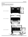
Tube Integrated Amplifier
MA2275
Owner’s Manual
McIntosh Laboratory, Inc. 2 Chambers Street Binghamton, New York 13903-2699 Phone: 607-723-3512 FAX: 607-724-0549
The lightning flash with arrowhead,
within an equilateral triangle, is intended
to alert the user to the presence of
uninsulated “dangerous voltage” within
the product’s enclosure that may be of
sufficient magnitude to constitute a risk
of electric shock to persons.
WARNING - TO REDUCE RISK OF
FIRE OR ELECTRICAL SHOCK, DO
NOT EXPOSE THIS EQUIPMENT TO
RAIN OR MOISTURE.
IMPORTANT SAFETY
INSTRUCTIONS!
PLEASE READ THEM BEFORE
OPERATING THIS EQUIPMENT.
1. Read these instructions.
2. Keep these instructions.
3. Heed all warnings.
4. Follow all instructions.
5. Do not use this apparatus near water.
6. Clean only with a dry cloth.
7. Do not block any ventilation openings. Install in
accordance with the manufacturer’s instructions.
8. Do not install near any heat sources such as
radiators, heat registers, stoves, or other
apparatus (including amplifiers) that produce
heat.
9. Do not defeat the safety purpose of the polarized
or grounding-type plug. A polarized plug has two
blades with one wider than the other. A grounding
type plug has two blades and a third grounding
prong. The wide blade or the third prong are
provided for your safety. If the provided plug
does not fit into your outlet, consult an electrician
for replacement of the obsolete outlet.
10. Protect the power cord from being walked on or
pinched particularly at plugs, convenience
receptacles, and the point where they exit from
the apparatus.
2
The exclamation point within an equilateral triangle is intended to alert the
user to the presence of important
operating and maintenance (servicing) instructions in the literature accompanying the appliance.
NO USER-SERVICEABLE PARTS
INSIDE. REFER SERVICING TO
QUALIFIED PERSONNEL.
To prevent the risk of electric shock, do not remove cover or
back. No user serviceable parts inside.
11. Only use attachments/accessories specified by the
manufacturer.
12. Use only with the cart, stand, tripod, bracket, or
table specified by the manufacturer,
or sold with the apparatus. When a
cart is used, use caution when moving
the cart/apparatus combination to
avoid injury from tip-over.
13. Unplug this apparatus during lightning storms or
when unused for long periods of time.
14. Refer all servicing to qualified service personnel.
Servicing is required when the apparatus has
been damaged in any way, such as power-supply
cord or plug is damaged, liquid has been spilled
or objects have fallen into the apparatus, the
apparatus has been exposed to rain or moisture,
does not operate normally, or has been dropped.
15. Do not expose this equipment to dripping or
splashing and ensure that no objects filled with
liquids, such as vases, are placed on the
equipment.
16. To completely disconnect this equipment from
the a.c. mains, disconnect the power supply cord
plug from the a.c. receptacle.
17. The mains plug of the power supply cord shall
remain readily operable.
Thank You
Table of Contents
Your decision to own this McIntosh MA2275 Tube Integrated Amplifier ranks you at the very top among discriminating music listeners. You now have “The Best.” The
McIntosh dedication to “Quality,” is assurance that you
will receive many years of musical enjoyment from this
unit.
Please take a short time to read the information in this
manual. We want you to be as familiar as possible with all
the features and functions of your new McIntosh.
Safety Instructions ............................................................ 2
Thank You and Please Take a Moment ............................. 3
Technical Assistance and Customer Service .................... 3
Table of Contents and Important Information .................. 3
Connector Information ..................................................... 4
Introduction ...................................................................... 4
Performance Features ....................................................... 4
Dimensions ....................................................................... 5
Installation of Tubes, Equipment Location
and Ventilation .................................................................. 6
Installation in a Custom Cabinet ...................................... 8
Top Panel Connections and Tube Locations .................... 9
Rear Panel Connections .................................................. 10
How to Connect Loudspeakers ....................................... 11
How to Connect Audio Components .............................. 12
How to Connect for a Second Room .............................. 13
Front Panel Controls, Displays, Push-Buttons
and Switch ...................................................................... 14
How to Operate ............................................................... 15
Remote Control Push-Buttons ........................................ 18
How to Operate by Remote Control ............................... 19
Specifications ................................................................. 22
Packing Instruction ......................................................... 23
Please Take A Moment
The serial number, purchase date and McIntosh Dealer
name are important to you for possible insurance claim or
future service. The spaces below have been provided for
you to record that information:
Serial Number:
Purchase Date:
Dealer Name:
Technical Assistance
If at any time you have questions about your McIntosh
product, contact your McIntosh Dealer who is familiar with
your McIntosh equipment and any other brands that may
be part of your system. If you or your Dealer wish additional help concerning a suspected problem, you can receive technical assistance for all McIntosh products at:
McIntosh Laboratory, Inc.
2 Chambers Street
Binghamton, New York 13903
Phone: 607-723-1545
Fax: 607-723-3636
Customer Service
If it is determined that your McIntosh product is in need of
repair, you can return it to your Dealer. You can also return
it to the McIntosh Laboratory Service Department. For assistance on factory repair return procedure, contact the
McIntosh Service Department at:
McIntosh Laboratory, Inc.
2 Chambers Street
Binghamton, New York 13903
Phone: 607-723-3515
Fax: 607-723-1917
Copyright 2004 © by McIntosh Laboratory, Inc.
Important Information
1. Caution: To prevent electrical shock make sure the AC
POWER CORD IS NOT CONNECTED TO THE
MA2275 . Also do not touch the Vacuum Tube
Connection Pins when inserting or removing them,
as there may be hazardous voltages present at the
Tube Socket Pins even after the MA2275 has been
switched Off for a period of time.
2. When Vacuum Tubes are installed or removed, reattach the
Tube Cover with the Original Tube Cover Screws.
3. If the MA2275 has been On, please allow the Hot Vacuum
Tubes to cool first before removing them.
4. The following Connecting Cable is available from the
McIntosh Parts Department:
Data and Power Control Cable Part No. 170-202
Six foot, 2 conductor shielded, with two 1/8 inch stereo
mini phone plugs.
5. For additional connection information, refer to the owner’s
manual(s) for any component(s) connected to the MA2275.
6. It is very important that loudspeaker cables of adequate size
be used, so that there will be minimum power loss. The size is
specified in Gauge Numbers or AWG (American Wire Gauge).
The smaller the Gauge number, the larger the wire size.
Connection Terminals will accept up to a 8 AWG wire size:
If your loudspeaker cables are 50 feet (38.1m) or less,
use at least 14 Gauge.
If your loudspeaker cables are 100 feet (76.2m) or less,
use at least 12 Gauge.
3
Introduction and Performance Features
Connector Information
XLR Connectors
Below is the Pin configuration for the XLR Balanced Input
Connectors on the MA2275. Refer to the diagram for connection:
Pin 2
PIN 1: Shield/Ground
PIN 2: + Input
Pin 1
PIN 3: - Input
Pin 3
Power Control Connectors
The MA2275’s Power Control Outputs provide a 5 volt
signal. Use a 1/8 inch stereo mini
phone plug to connect to the
Positive
Power Control Input on other
N/C
McIntosh Components.
Ground
Data Port Connectors
The MA2275’s Data Port Output provides Remote Control
Signals. Use a 1/8 inch stereo
mini phone plug to connect to the Data Signal
Data Port Inputs on McIntosh
N/C
Source Units.
Ground
Introduction
Now you can take advantage of traditional McIntosh standards of excellence in the MA2275 Tube Integrated Amplifier. The versatile Preamplifier together with two 75 watt
Power Amplifier Channels provide all the electronics necessary to drive any high quality Loudspeaker System. The
MA2275 reproduction is sonically transparent and absolutely accurate. The McIntosh Sound is “The Sound of the
Music Itself.”
Performance Features
•
Power Output
The MA2275 has two separate power amplifier channels,
each capable of 75 watts into 2, 4 or 8 ohm Loudspeakers.
•
Bifilar Wound Transformers and Output Circuit
The Power Output Circuitry utilizes the famous McIntosh
Patented Unity Coupled Circuit with a Bifilar Wound Output Transformer for low distortion, extended frequency response and cool operating output tubes.
•
Electronic Input Switching
Digital Logic integrated circuits drive Electromagnetic
Switches on all inputs and operating functions for reliable,
noiseless, distortion free switching.
4
•
Balanced and Unbalanced Inputs
The MA2275 has five Inputs for high level program
sources and one Phono Input for a Moving Magnet Cartridge.
•
Tone Control Bypass
The Bass and Treble Control Circuit Elements can be removed from the Signal Path.
•
Low Distortion
Distortion levels of all types are less than 0.5%. Music is
amplified with total transparency and accuracy.
•
Remote Control Operation
A Remote Control is included that will allow control of
major front panel controls and switches. There are provisions for connecting External Keypad and/or Sensors,
which allows for enjoyment of your McIntosh System from
other rooms in your home.
•
Illuminated Power Meters
Peak responding Power Output Meters will indicate either
continuously or in a peak hold mode for each channel.
There is also a Meter Illumination Off Mode if desired.
•
Gold Plated Connectors and Tube Socket Contacts
Gold Plated Input Jacks and Output Binding Posts provide
trouble free connections. Ceramic tube sockets with gold
plated contacts provide protection from atmospheric contamination. Output Tube Sockets include Air-Pipe cooling
at their bases.
•
Fiber Optic Solid State Front Panel Illumination
The even Illumination of the Glass Front Panel is accomplished by the combination of custom designed Fiber Optic
Light Diffusers and extra long life Light Emitting Diodes
(LEDs).
•
Super Mirror Chassis Finish
The Stainless Steel Chassis with Super Mirror Finish ensures the pristine beauty of the MA2275 will be retained
for many years.
Dimensions
Dimensions
The following dimensions can assist in determining the
best location for your MA2275. There is additional information on page 8 pertaining to installing the MA2275 into
cabinets.
17-3/4"
45.09cm
8-7/8"
22.54cm
Front View of the MA2275
10-1/8"
25.72cm
16-3/4"
42.55cm
Rear View of the MA2275
13-11/16"
34.77cm
17-3/4"
45.09cm
17"
43.18cm
Side View of the MA2275
8-1/8"
20.64cm
9-3/4"
24.77cm
3/4"
1.91cm
12-3/4"
3-5/16"
32.39cm
5.87cm
5
Installation of Tubes and Tube Cover
Caution: To prevent electrical shock make sure the AC
POWER CORD IS NOT CONNECTED TO THE
MA2275 . Also do not touch the Vacuum Tube
Connection Pins when inserting or removing them,
as there may be hazardous voltages present at the
Tube Socket Pins even after the MA2275 has been
switched Off for a period of time.
Your MA2275 has gone through an extensive series of performance tests during the manufacturing process. The
MA2275 is supplied with the actual Tubes that were used
to test and confirm the performance of this integrated amplifier. To protect the Vacuum Tubes from possible shipping damage, they are packed in five layers of foam,
placed into the Tube Cover and secured to the MA2275
Chassis.
Note: Gloves or a soft cloth will prevent “fingerprinting” of
the Tubes during their installation.
1. Orient the MA2275 so the right Side Panel is facing
you. Refer to figure 1.
2. Using an appropriate screwdriver, remove the Tube
Cover Fastening Screw.
3. In a similar manner, remove the Tube Cover Fastening Screw from the left side of the integrated amplifier.
4. Remove the tube cover from the MA2275 Chassis.
5. Orient the Tube Cover to the wide opening along one
side of its longer dimension. Refer to figure 2.
6. Remove the first layer of foam to expose the Tubes.
Refer to figure 3.
7. Carefully remove the Tubes from the foam and temporarily place them in a safe location.
8. Remove the remaining foam from the Tube Cover
and retain all five pieces for possible future use.
The MA2275 Chassis has nomenclature screened on it to
specify the location in the circuit and Tube Type for each
channel. Refer to figure 4.
Note: It is extremely important to insert the Tubes in the
correct location.
Power Output Tubes:
1. Orient the Chassis so the Front Panel of the Amplifier
is facing you.
2. Locate a KT88 or 6550 Power Output Tube.
3. On the top left side of the amplifier, locate the Tube
Socket that has the nomenclature V3L KT88/6550
next to it on the chassis.
4. Orient the Tube so the key on the base of the Tube is
aligned with the corresponding key on the Tube
Socket.
5. Carefully insert the Tube into the socket until the base
of the Tube is fully seated in the Tube Socket.
6
Tube Cover
Fastening
Screw
Location
Figure 1
Tube Cover with
Layers of Foam
and Tubes
Figure 2
Power Output Tubes
Small Signal Tubes
Figure 3
V3L - KT88/6550 Tube
V4 - 12AX7A Tube
V1R - 12AT7 Tube
Figure 4
Installation of Tubes, Tube Cover, Location and Ventilation
6. Repeat the above the steps for the remaining 3 Power
Output Tubes.
There are two different types of Small Signal Tubes
(12AX7A and 12AT7) used in each channel. Tube type can
be found on the outside of the Tube. The MA2275 will not
function if they are inserted into the wrong socket.
Small Signal Tubes:
1. Locate a 12AX7A Tube.
2. On the top center area of the amplifier, locate the
Tube Socket that has the nomenclature V4 12AX7A
next to it on the chassis. Refer to figure 4.
3. Orient the Tube so the area where no pins are located
on the base of the Tube is aligned with the corresponding area on the Tube Socket.
4. Carefully insert the Tube into the socket until the base
of the Tube is fully seated in the Tube Socket.
5. Repeat the above steps for the remaining three
12AX7A Tubes. Refer to figure 5.
6. Locate a 12AT7 Tube.
7. On the right side of the amplifier, locate the Tube
Socket that has the nomenclature V1R 12AT7 next to
it on the chassis. Refer to figure 4.
8. Insert the Tube, following the same procedure as in
steps 3 and 4.
9. Repeat steps 6-9 for the remaining 12AT7 Tube. Refer to figure 5.
12AX7A
KT88/
6550
KT88/
6550
12AT7
Figure 5
Tube Cover
Tube Cover Fastening Screw Locations
Caution: To prevent electrical shock make sure the MA2275
Tube Cover is installed before connecting the AC
Power Cord.
Before operating the MA2275, locate the previously removed Tube Cover and perform the following steps:
Installing the Tube Cover:
1. The Tube Cover has a wide opening along one side
of its longer dimension. Orient this wide opening so
it is facing towards you.
2. Carefully place the Tube Cover onto the MA2275.
Refer to figure 6.
3. Using an appropriate screwdriver secure the Tube
Cover to the chassis using the previously installed
screws.
Fastening
Screw
Location
Tube Cover
Figure 6
Warm Air
Location and Ventilation
Adequate ventilation extends the trouble free life of the
MA2275. The suggested minimum space for operating the
MA2275 is 24 inches (60.96cm) in width, 20 inches
(50.8cm) depth, and 22.5 inches (57.15cm) in height. Always allow air to flow through the ventilation holes on the
bottom of the amplifier and a means for the warm air to escape at the top, refer to figure 7. For installation of the
MA2275 into a cabinet, refer to the next page.
Cool Air
Figure 7
7
Installation in a Custom Cabinet
The MA2275 can be placed upright on a table or shelf,
standing on its four feet. It also can be custom installed in a
piece of furniture or cabinet of your choice. The four feet
may be removed from the bottom of the MA2275 when it
is custom installed as outlined below. The four feet
together with the mounting
screws should be retained
for possible future use if the
MA2275 is removed from
the custom installation and
used free standing. Install
MA2275 Front Panel
the four supplied chassis
Custom Cabinet Cutout
spacers into the threaded
openings on the bottom located next to the just removed four feet. The required panel cutout, ventilation cutout and unit dimensions are shown.
Cabinet
Always provide adFront
equate ventilation for your
Panel
MA2275. Cool operation
ensures the longest possible
Opening
for Ventilation
operating life for any electronic instrument. Do not
install the MA2275 directly
above a heat generating
component such as a high MA2275 Side View
powered amplifier. If the
in Custom Cabinet
MA2275 is installed in a
cabinet, a quiet running
ventilation fan can be a
definite asset in maintaining the coolest possible operating temperature.
Support
Shelf
A custom cabinet installation should provide the
following minimum spacing dimensions for cool operation. Allow at least 12
inches (30.48cm) above the
MA2275 Bottom View
top, 2 inches (5.08cm) bein Custom Cabinet
low the bottom and 3
inches (7.62cm) on each
side of the amplifier, so that
airflow is not obstructed.
Allow 20 inches (50.8cm)
2"
depth behind the front
5.08cm
8
panel. Allow 1 inch (2.54cm) in front of the mounting
panel for knob clearance. Be sure to cut out a ventilation
hole in the mounting shelf according to the dimensions in
the drawing.
17-1/4"
43.82cm
8-1/4"
20.96cm
Cutout Opening for Custom Mounting
12"
30.48cm
Cutout Opening for Ventilation
Chassis
Spacers
1-7/8"
4.76cm
13-11/16"
34.77cm
Cutout Opening
for Ventilation
13-1/8"
33.34cm
9-3/16"
10-5/16"
23.34cm
26.19cm
Top Panel Connections and Tube Locations
V3R
KT88/
6550
V2L
KT88/
6550
V1R
12AT7
V1L
12AT7
V2R
KT88/
6550
V3L
KT88/
6550
RIGHT Channel OUTPUTs
connections for 2 ohm, 4 ohm
and 8 ohm Loudspeakers
V6
12AX7A
V7
12AX7A
V4
12AX7A
LEFT Channel OUTPUTs
connections for 2 ohm, 4 ohm
and 8 ohm Loudspeakers
V5
12AX7A
9
Rear Panel Connections
External SENSOR
or Keypad Jack
permits the connection of a McIntosh IR Sensor or
Keypad for remote
operation
Main Fuse holder,
refer to information
on the back panel
of your MA2275 to
determine the correct fuse size and
rating
Connect the
MA2275 power cord
to a live AC outlet.
Refer to information
on the back panel to
determine the correct
voltage
POWER CONTROL
MAIN Output sends
a turn-on signal to an
external McIntosh
Power Amplifier
when the MA2275 is
turned on
10
JUMPER PLUGS
connect the Preamplifier OUTPUTS
PREAMP 1 Jacks to
the POWER AMP IN
Jacks and are needed
for normal operation
POWER AMP IN
inputs accept signals from a separate external
preamplifier
POWER CONTROL
ACC Output sends a
turn-on signal to a
McIntosh Source
Component or Power
Control unit when the
MA2275 is turned on
TAPE, DVD, TUNER,
CD and CD2 INPUTS
accept unbalanced high
level program source
signals
TAPE OUTPUTS
provide the Record
Out Signal
PHONO Input accepts
signals from a Moving
Magnet Phono Cartridge
DATA PORTS send
signals to McIntosh
Compatible Components to allow control
with the Remote
Control
PREAMP OUTPUTS
1 and 2 supply the
Preamplifier Output
to either the internal
or external power amplifier
CD balanced INPUTS
accept high level program source signals
Ground
connection
for turntables
How to Connect Loudspeakers
How to Connect Loudspeakers
Caution: The supplied AC Power Cord should not be
connected to the Rear Panel of the MA2275
Integrated Amplifier until after Connections have
been made.
1. Prepare the Loudspeaker Hookup Cables that attach to
the MA2275 by choosing one of the methods below:
Bare wire cable ends:
Carefully remove sufficient insulation from the cable
ends, refer to figures 1, 2 & 3. If the cable is stranded,
carefully twist the strands together as tightly as possible.
Note: If desired, the
twisted ends can be
tinned with solder to
keep the strands
together, or attach spade lug and/or banana
connector.
Spade lug or prepared wire connection:
Insert the spade lug connector or prepared section of
the cable end into the terminal side access hole, and
tighten the terminal cap until the cable is firmly
clamped into the terminal so the wires cannot slip out.
Refer to figures 4, 5 & 6.
Right
Loudspeaker
4 ohm
Banana plug connection:
Insert the banana plug into the hole at the top of the
terminal.
Tighten the top
portion of the
terminal post
and the set
screw to secure
the banana plug
in place.
Note: The use of Banana Plugs is for use in the United
States and Canada only. Refer to figures 7 and 8.
2. Connect the Loudspeaker hookup cables to the output
terminals that match the impedance of the Loudspeaker, being careful to observe the correct polarities. Output impedance connections of 2S (ohm), 4S (ohm) and
8S (ohm) are provided. If the Loudspeaker’s impedance is in-between the available connections, use the
nearest lower impedance connection.
WARNING: Loudspeaker terminals are hazardous live
and present a risk of electric shock. For
additional instruction on making
Loudspeaker Connections contact your
McIntosh Dealer or McIntosh Technical
Support.
Left
Loudspeaker
4 ohm
11
How to Connect Audio Components
How to Connect Audio Components
1. Connect an Audio Cable from the McIntosh CD Player
Audio Outputs to the MA2275 CD INPUTS.
2. Connect an Audio Cable from the McIntosh Tuner
1 Outputs to the MA2275 TUNER INPUTS.
3. Connect an Audio Cable from a Turntable to the
PHONO INPUTS and the Turntable Ground Connection to the GND grounding post.
4. Connect an Audio Cable from the MA2275 TAPE
OUTPUTS to the Record Inputs of a Tape Recorder
and from the MA2275 TAPE INPUTS to the Tape Recorder Outputs.
5. Connect a Control Cable from the MA2275 POWER
CONTROL ACC Jack to the Power Control In on the
McIntosh Tuner.
6. Connect a Control Cable from the McIntosh Tuner
Power Control Out Jack to the Power Control In jack
on the McIntosh CD Player.
7. Connect a Control Cable from the MA2275 TUNER
DATA PORT Jack to the McIntosh Tuner Data In
(Tuner 1).
8. Connect a Control Cable from the MA2275 CD2
DATA PORT Jack to the McIntosh CD Player Data In
Jack.
9. Connect the MA2275 Power Cord to a live AC outlet.
McIntosh Tuner
McIntosh CD Player
To AC Outlet
In
12
Tape Recorder
Out
Turntable
How to Connect for a Second Room
How to Connect for a Second Room
1. Connect Audio Cables from the MA2275 OUTPUTS
PREAMP 2 to the second Power Amplifier Inputs.
2. Connect Hookup Cables from the second Power Amplifier to the Loudspeakers. Refer to page 11 in this
Owner’s Manual for connection details.
3. Connect a Control Cable from the MA2275 POWER
CONTROL MAIN Jack to the Power Control In of a
McIntosh Power Amplifier.
4. Connect an RG6 or RG59U coaxial cable from the
EXTernal SENSOR Jack to a McIntosh Keypad.
Keypad
Note: A Wall Mounted IR Sensor may also be used in
place of the Keypad.
McIntosh Power Amplifier
Right
Loudspeaker
4 ohm
Left
Loudspeaker
4 ohm
13
Front Panel Controls, Displays, Push-Buttons and Switch
METER indicates the
Power Output of the Left
Channel Amplifier
INPUT SELECTOR
Control selects the program signals that are
listened to and are
available for recording
HEADPHONES
jack accepts dynamic headphones
BASS Control provides 12dB boost or
cut with a flat center
position
REC MONITOR Push-button with indicator, allows
listening to the tape playback while the recording is
in process
IR Sensor receives
commands from a
remote control
14
TREBLE Control provides
12dB boost or cut with a
flat center position
METER indicates the
Power Output of the Right
Channel Amplifier
METER Control selects
the display modes of the
Power Output Meter
MONO Push-button
combines left and right
stereo signals to mono
at the Headphones and
PREAMP OUTPUTS
1&2
TONE BYPASS Push-button
allows the audio signal to totally bypass the Tone Control
Circuitry
VOLUME Control
adjusts the listening
volume level of the
Loudspeakers and
Headphones
The BALANCE
Control adjusts the
relative volume balance between channels
STANDBY/ON
Push-button turns
the MA2275 ON
or OFF (Standby)
MUTE Push-button
mutes the listening
audio
POWER Switch
turns all AC
power completely
ON or OFF
TUBE WARMUP
indicates when the
audio output is muted
until the tubes reach
operating temperature
How to Operate the MA2275
How to Operate the MA2275
Power On and Off
Press the POWER switch to ON, the Red LED above the
STANDBY/ON Push-button lights to indicate the MA2275
is in Standby Mode. To
Switch On the MA2275
press the STANDBY/
ON Push-button on the
Front Panel or the
POWER Push-button on
Figure 9
the Remote Control.
The title TUBE WARMUP will illuminate on the Front
Panel (located to the right of the STANDBY/ON Push-button) with the Audio Outputs muted until the tubes reach
operating temperature. Refer to figures 9 and 10.
Notes: 1. For normal
operation, switch the
MA2275 On and Off
with the Standby/On
Push-button. If the
Tube Integrated
Amplifier is not going
to be used for an
extended period of
time, turn Off all AC
Power with the
Power Switch on the
Front Panel.
2. The amount of time
required for Tube
Warmup is dependant
upon the temperature
of the Tubes inside
the MA2275 when the
STANDBY/ON Pushbutton is depressed.
3. If there is an
interruption of AC
Power to the MA2275
while it is On, the
internal circuitry will
sense this condition
and will
automatically switch
the MA2275 back On
when AC Power is
restored.
Input Source Selection
Select the desired Source with
Figure 10
the INPUT Selector Control
or the Source Push-button on the Remote Control.
Bass and Treble Controls
Adjust the BASS and TREBLE controls to suit your listening preferences. The Bass or Treble intensity can be increased with clockwise rotation and decreased with counterclockwise rotation.
Meter Mode Selection
Rotate the Meter Mode Switch to select the meter operation mode you desire. Refer to figure 11 and 12.
Lights Off - Meter lights are turned off and the meter will
continue to indicate
the power output.
Watts- The meters respond to
all the musical information being produced by the amplifier. They indicate to
an accuracy of at least
95% of the power
Figure 11
output with only a
single cycle of a 2000Hz tone burst.
Figure 12
Hold - The meter pointer is locked to the highest
power peak in a sequence of peaks. It is electronically held to this power level until a
higher power peak passes through the amplifier. The meter pointer will then rise to the
newer higher indication. If no further power
peaks are reached, the meter pointer will very
slowly return to its rest position or lower
power level. The decay rate is approximately
6dB per minute.
Balance Control
Adjust the BALANCE Control as needed to achieve approximately equal listening volume levels in each Loudspeaker. Rotate the BALANCE Control clockwise to emphasize the Right Channel by reducing the volume level of
the Left Channel. Rotate the BALANCE Control counterclockwise to de-emphasize the Right Channel until equal
Balance of both Channels is achieved.
15
How to Operate the MA2275, con’t
Volume Control
Adjust the VOLUME Control
or press the UpS /DownT
Push-buttons on the Remote
Control for the desired listening level. Refer to figure 13.
Reset of Microprocessors
In the event the controls of the MA2275 stop functioning,
push the POWER switch OFF and wait about two minutes.
Then push the POWER switch ON followed by pushing
the STANDBY/ON Push-button. This will reset the
MA2275 microprocessors and the Tube Integrated Amplifier should be functioning normally.
Record Monitor
Press the REC MONITOR
Push-button to hear the TAPE
Playback Signal during the
recording process. Refer to
figure 14.
Note: The above condition is usually caused by either
interruptions in AC power and/or major changes that
may occur in AC power line voltage.
Using a Separate Power Amplifier
There are two different ways to use a separate power amplifier with a MA2275. The first way is to use the separate
amplifier instead of the MA2275 built-in Power Amplifier.
Connect the Loudspeakers to the separate
power amplifier and remove the McIntosh
Jumpers that are located between the OUTPUTS 1 Jacks and the POWER AMP INput
Jacks. Refer to figures 15 and 16.
Tone Bypass
Press the TONE BYPASS
Push-button to totally Bypass
the Tone Control Circuitry,
providing a flat frequency response.
Note: The McIntosh Jumpers must be
connected, between the above
mentioned jacks, when the MA2275
Internal Power Amplifier is to be used.
Note: The MA2275 will
automatically remember
for each input whether
the Tone Bypass is
active.
Mono
Press the MONO Mode Pushbutton to combine Left and
Right Stereo Signals to Mono,
for the Loudspeaker Outputs,
PREAMP OUTPUTs 1&2 and
Figure 13
the HEADPHONES Jack. The
MODE Push-button on the
Remote Control also can be used to switch between the
Stereo and Mono Modes of Operation. Refer to figure 13.
Note: The TAPE Outputs are not effected by the Mono Mode
of Operation.
Mute
Press the MUTE Push-button to Mute the Audio at the
Loudspeaker Outputs and PREAMP OUTPUTS 1 & 2. An
LED above MUTE Push-button, on the front panel, will
flash On and Off during the time the audio is muted.
The second way is to use both a separate
power amplifier and the MA2275 built-in
Power Amplifier. Connect one pair of Loudspeakers to the separate power amplifier
and the second pair to the MA2275. Refer
to page 13 for connection information.
Figure 16
Note: The MA2275 VOLUME Control will affect the sound
level of all the Loudspeakers.
How To Make A Tape Recording
1. Select the source signal you wish to record using the
INPUT SELECTOR Control.
2. Adjust the record level using the tape recorder volume
control and proceed with the recording process.
3. Press the REC MON Push-button and listen to the tape
playback of the just recorded program source selected.
Figure 14
16
Figure 15
Note: The MA2275 TAPE OUTPUTS are not affected by the
VOLUME or BALANCE controls.
Notes
17
Remote Control Push-Buttons
Press to Power the MA2275
ON or OFF
Turns AC Power ON or OFF to
certain McIntosh Components
when connected via the Data Port
Selects one of the available
Audio Sources
Press the push-button
to illuminate the keys
Selects On Screen Functions for McIntosh certain
Disc Players
Selects Disc Player or
Tape Recorder Functions
and also performs various
functions on a variety of
McIntosh Components
Press to REVIEW Tuner
Station Presets and select
certain functions on
McIntosh Disc Players
Selects the Fast Forward
Mode on Disc Players
and Tunes Up the AM/
FM Dial
Selects the REWind
Mode on Disc Players
and Tunes Down the
AM/FM Dial
Press MODE to switch
between Stereo or Mono
Channel Modes
Use to select tuner
presets, disc tracks or
any numbered operation
Selects AM Tuner Operating Functions and Disc
Selection on certain
McIntosh Disc Players
Selects FM Tuner Operating Functions and Track
Selection on certain
McIntosh CD Players
Adjusts the volume
level Up or Down
Mutes the audio
Note: The TRIM Push-buttons and HOME Push-button
are for use with other McIntosh Products.
18
How to Operate by Remote Control
How to Operate by Remote Control
The supplied Remote Control is capable of directly controlling the functions of contemporary McIntosh Source Components connected to the MA2275. Earlier McIntosh
source components and other brand source components can
be controlled by the MA2275 with the addition of a McIntosh Remote Control Translator (RCT).
Note: Your McIntosh Dealer can assist you with the
installation and operation of the Remote Control
Translator (RCT).
Mute
Press the MUTE Push-button to mute audio at the Loudspeaker and Headphone Outputs. Press MUTE a second
time to unmute audio.
Mode
Press the MODE Push-button to select between Stereo and
Mono Modes of operation.
E
Press E to perform various functions on a variety of
McIntosh Components. It will also pause the playing of a
Disc or Tape playback.
Lighting
Press and release the LIGHTING Push-button to momentarily illuminate the upper half of the Remote Control
Push-buttons.
Note: While the LIGHTING Push-button is being depressed
the Remote Control will be unable to send a remote
command. When the LIGHTING Push-button is released
the push-buttons will continue to stay illuminated for
approximately three seconds thus allowing you to send
the desired command.
Input Source Selection
Press one of the Input Push-buttons to select the desired
program source.
Disc/Tape Functions
Use these push-buttons to operate a Disc Player or Tape
Recorder.
Numbered Push-buttons
Press Push-buttons 0 through 9 to access tuner station presets or Disc chapters/tracks/discs.
Disc and Track
Use the DISC and TRACK Push-buttons when a Disc
Players is being used.
Note: Certain Disc Players will require a Numbered Pushbutton be pressed immediately after the Disc or Track
Push-button is depressed.
Volume
Press the UpS or DownT VOLUME Push-button to raise
or lower the listening volume level.
Note: The TAPE OUPUTS are not affected by volume
changes.
Acc On/Acc Off
Press ACC ON to turn the power ON to certain McIntosh
Disc Players. Press ACC OFF to turn the power OFF to
certain McIntosh Disc Players. The ACC ON/OFF Pushbuttons also control the signal at the ACCessory(B) Power
Control Jack; it will also remember the last command when
the MA2275 is switched Off and On again.
19
20
Notes
21
Specifications
Specifications
Power Output
Minimum sine wave continuous average power output per
channel, both channels operating is:
75 watts into 2 ohm load
75 watts into 4 ohm load
75 watts into 8 ohm load
Voltage Gain
High Level to Tape: 0dB
High Level to Main: 20dB
Rated Power Band
20Hz to 20,000Hz
Power Requirements
100 Volts, 50/60Hz at 3.6 amps
110 Volts, 50/60Hz at 3.6 amps
120 Volts, 50/60Hz at 3.6 amps
220 Volts, 50/60Hz at 1.8 amps
230 Volts, 50/60Hz at 1.8 amps
240 Volts, 50/60Hz at 1.8 amps
Total Harmonic Distortion
Maximum Total Harmonic Distortion at any power
level from 250 milliwatts to rated power output is:
0.5% for 2, 4 or 8 ohm loads
Frequency Response
+0, -0.5dB from 20Hz to 20,000Hz
+0, -3dB from 10Hz to 50,000Hz
Sensitivity
Phono: 2.5mV for 2.5V rated output (0.5mV IHF)
High Level: 250mV for 2.5V rated output (50mV IHF)
Power Amplifier Input: 2.5V for rated output
A-Weighted Signal To Noise Ratio
Phono Input: 80dB below 10mV input
High Level: 93dB below rated output
Power Amplifier: 100dB below rated output
Intermodulation Distortion
Maximum Intermodulation Distortion if instantaneous peak output does not exceed twice the rated
output, for any combination of frequencies from
20Hz to 20,000Hz is:
0.5% for 2, 4 or 8 ohm loads
Input Impedance
Phono: 47K ohms, 65pF
High: Level, 22K ohms
Maximum Input Signal
Phono: 90mV
High Level: 8V
Preamplifier Maximum Voltage Output
Phono: 8V
High Level: 8V
Main Out: 8V at preamp output
22
Wide Band Damping Factor
Greater than 18
Note: Refer to the rear panel of the MA2275 for the correct
voltage.
Preamplifier Tube Compliment
2 - 12AX7A Phono Circuitry
2 - 12AX7A High Level Circuitry
Power Amplifier Tube Compliment
2 - 12AT7
4 - KT88/6550
Overall Dimensions
Width is 17-3/4 inches (45.09cm)
Height is 10-1/8 inches (25.72cm) including feet
Depth is 18-3/4 inches (47.63cm) including the Front Panel
and Knobs
Weight
77 pounds (35 kg) net, 110 pounds (50 kg) in shipping carton
Packing Instructions
Packing Instructions
In the event it is necessary to repack the equipment for
shipment, the equipment must be packed exactly as described and shown below.
The MA2275 Vacuum Tubes must be removed from the
Amplifier Tube Sockets and placed into the inside openings of the five layer foam packing material. The foam
with the tubes located inside are placed into the Amplifier
Tube Cover and secured to the Chassis. Failure to do this
will result in damage to the Vacuum Tubes and possibly the
MA2275.
Four 1/4 - 20 x 2-1/4 inch cap screws and flat washers
must be used to fasten the unit securely to the Shipping
Skid. This will ensure the proper equipment location in the
Inner Carton. Failure to do this will result in shipping damage.
Use the original shipping carton and interior parts only
if they are all in good serviceable condition. If a shipping
carton or any of the interior part(s) are needed, please call
or write Customer Service Department of McIntosh Laboratory. Please see the Part List for the correct part numbers.
Quantity
1
1
2
2
2
Part Number
034052
034051
034054
034186
034187
Description
Shipping carton top
Shipping carton bottom
Foam Pad (top and bottom)
Foam Pad (front and rear)
Foam Pad (sides)
2
2
034180
034179
Foam pack tube (ends)
Foam pack tube (inside with
tube cutouts)
1
1
1
1
4
4
034136
034137
034008
034161
101212
104058
Inner carton top
Inner carton bottom
Bottom pad
Shipping skid
1/4 - 20x2-1/4 cap screw
Flat washer
23
McIntosh Laboratory, Inc.
2 Chambers Street
Binghamton, NY 13903
The continuous improvement of its products is
the policy of McIntosh Laboratory Incorporated
who reserve the right to improve design without
notice.
Printed in the U.S.A.
McIntosh Part No. 04089100