1
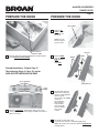
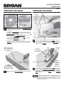
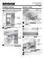
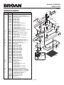
ALLURE® QS2 SERIES
RANGE HOOD
Page 1
®
ALLURE
QS2 SERIES RANGE HOOD
Patent No.:
US D450, 829 S
READ AND SAVE THESE INSTRUCTIONS
!
FOR DOMESTIC COOKING ONLY
!
!
WARNING
CAUTION
TO REDUCE THE RISK OF FIRE, ELECTRIC SHOCK, OR INJURY
TO PERSONS, OBSERVE THE FOLLOWING:
1. Use this unit only in the manner intended by the manufacturer. If
you have questions, contact the manufacturer at the address or
telephone number listed in the warranty.
2. Before servicing or cleaning unit, switch power off at service panel
and lock the service disconnecting means to prevent power from
being switched on accidentally. When the service disconnecting
means cannot be locked, securely fasten a prominent warning
device, such as a tag, to the service panel.
3. Installation work and electrical wiring must be done by a qualified
person(s) in accordance with all applicable codes and standards,
including fire-rated construction codes and standards.
4. Sufficient air is needed for proper combustion and exhausting of
gases through the flue (chimney) of fuel burning equipment to
prevent backdrafting. Follow the heating equipment manufacturer’s
guideline and safety standards such as those published by the
National Fire Protection Association (NFPA), and the American
Society of Heating, Refrigeration and Air Conditioning Engineers
(ASHRAE), and the local code authorities.
5. When cutting or drilling into wall or ceiling, do not damage electrical
wiring and other hidden utilities.
6. To reduce the risk of fire or electric shock, do not use this range
hood with an additional speed control device.
7. Ducted fans must always be vented to the outdoors.
8. To reduce the risk of fire, use only metal ductwork.
9. Use with approved cord-connection kit only.
10. This unit must be grounded.
TO REDUCE THE RISK OF A RANGE TOP GREASE FIRE:
1. Never leave surface units unattended at high settings. Boilovers
cause smoking and greasy spillovers that may ignite. Heat oils
slowly on low or medium settings.
2. Always turn hood ON when cooking at high heat or when cooking
flaming foods.
3. Clean ventilating fans frequently. Grease should not be allowed to
accumulate on fan or filter.
4. Use proper pan size. Always use cookware appropriate for the size
of the surface element.
TO REDUCE THE RISK OF INJURY TO PERSONS IN THE EVENT
OF A RANGE TOP GREASE FIRE, OBSERVE THE FOLLOWING:*
1. SMOTHER FLAMES with a close-fitting lid, cookie sheet, or metal
tray, then turn off the burner. BE CAREFUL TO PREVENT BURNS.
If the flames do not go out immediately, EVACUATE AND CALL
THE FIRE DEPARTMENT.
2. NEVER PICK UP A FLAMING PAN — You may be burned.
3. DO NOT USE WATER, including wet dishcloths or towels - violent
steam explosion will result.
4. Use an extinguisher ONLY if:
A. You know you have a Class ABC extinguisher and you already
know how to operate it.
B. The fire is small and contained in the area where it started.
C. The fire department is being called.
D. You can fight the fire with your back to an exit.
* Based on “Kitchen Fire Safety Tips” published by NFPA.
1. For indoor use only.
2. For general ventilating use only. Do not use to exhaust hazardous or explosive materials and vapors.
3. To avoid motor bearing damage and noisy and/or unbalanced
impellers, keep drywall spray, construction dust, etc. off power
unit.
4. For best capture of cooking impurities, your range hood should
be mounted so that the top of the hood is 24-30” above the
cooking surface.
5. Please read specification label on product for further information
and requirements.
Installer: Leave this manual with
the homeowner.
Homeowner: Operating and
Cleaning information on page 6.
NOTE
If hood is to be installed Non-Ducted:
Purchase a set of (2) non-ducted filters from your
local distributor or retailer and attach them to the
aluminum mesh filters.
TABLE OF CONTENTS
This manual is divided into sections as follows:
“PREPARE HOOD LOCATION”
Run ductwork from roof or wall cap, and electrical wiring from
service panel - to installation location
“PREPARE THE HOOD”
Get your hood ready for installation
“CONNECT WIRING”
Make electrical wiring connections to hood
“INSTALL HOOD”
Secure hood to cabinet and ductwork - install bulbs and filters
“OPERATION”
How to use the hood controls
“CLEANING”
Keep your hood in top working condition
“SERVICE PARTS”
Part numbers and exploded view of hood components
“WARRANTY”
One-year limited warranty and how to contact us
Register your product online at: www.broan.ca/register
ALLURE® QS2 SERIES
RANGE HOOD
Page 2
PREPARE HOOD LOCATION
PREPARE THE HOOD
ROOF CAP
3¼" X 10"
(For vertical
discharge)
FILTERS
SOFFIT
HOUSE WIRING
(Top or Back of hood)
CABINET
WALL CAP
HOOD
1
24" - 30" ABOVE
COOKING SURFACE
1
2
3¼" X 10" DUCT
(For horizontal discharge)
Determine whether hood will discharge vertically (3¼” x 10”),
or horizontally (3¼” x 10” only). For vertical or horizontal discharge, run ductwork between the hood location and a roof
cap or wall cap. For best results, use a minimum number of
transitons and elbows.
Use diagrams, below, for proper placement of ductwork and
electrical cutout in cabinet or wall. For a non-ducted installation, DO NOT cut a duct access hole.
Remove tape holding Filters in place. Pull down on filter
tabs or finger holes and lift filters out. Set filters aside.
TEFLON®COATED
BOTTOM
COVER
(Held in
place with
2 screws)
3¼” X 10”
HOOD MOUNTING SCREWS (4)
VERTICAL DUCTING
1315/16" (30" hood)
15/
15/
13 16" (30" hood)
16 16" (36" hood)
1615/16" (36" hood)
1915/16" (42" hood)
1915/16" (42" hood)
CABINET FRONT
2
7½"
CABINET BOTTOM
5¼"
5¼"
2"
VERTICAL DUCT
ACCESS HOLE
5"
1¼"
WOOD SHIMS
(recessed-bottom
cabinets only)
WOOD SHIMS
(recessed-bottom
cabinets only)
3
10½"
Remove Teflon®-coated bottom cover from hood. Set
cover and mounting screws aside.
Teflon® is a registered trademark of DuPont.
1½"
CENTER
LINE
ELECTRICAL
ACCESS HOLE
(in cabinet bottom)
DAMPER/
DUCT
CONNECTOR
3¼” X 10”
HORIZONTAL DUCTING
CABINET FRONT
1/8"
¾"
DUCT
3¾" HORIZONTAL
ACCESS HOLE
CABINET
5¼"
5¼"
BOTTOM
7½"
1315/16" (30" hood)
1315/16" (30" hood)
1615/16" (36" hood)
1615/16" (36" hood)
1915/16" (42" hood)
1915/16" (42" hood)
HOOD
ELECTRICAL
MOUNTING
CENTER
ACCESS HOLE
SCREWS (4)
LINE
(in wall)
Run house wiring between service panel and hood location.
3
Remove Damper/Duct Connector from inside the hood.
Set connector aside - with mounting screws and parts bag.
ALLURE® QS2 SERIES
RANGE HOOD
Page 3
PREPARE THE HOOD
PREPARE THE HOOD
AIR CHUTE
6
Remove Air
Chute - held in
place with one
(1) screw.
NOTE: Be careful not to disconnect any wires.
ELECTRICAL
CABLE CLAMP
Remove either top or back wiring knockout and install approved Electrical Cable Clamp.
7
Remove Baffle
from air chute.
Tabs will disengage
from Slots.
TABS
SLOTS
»
4
BAFFLE
Ducted Installation - Skip to Step 11.
The following Steps (5 thru 10) are for
NON-DUCTED INSTALLATION ONLY.
»
(3) #8 SCREWS
SUPPORT FIN
(2) #8 SCREWS
LIGHT
PANEL
8
5
Remove Light Panel - held in place with (3) #8 screws
and (2) #8 screws. Disconnect light assembly wire harness
(white connector).
9
Rotate baffle. Reinsert
baffle into air chute (as
shown) so that baffle fits
all the way into
into air chute. An audible
“click” will
be heard when
fully installed.
This will direct
air flow through
the non-ducted
slots on top
of hood.
»
»
Re-install air chute and screw,
re-connect wire harness, and replace light panel.
NOTE: Be careful not to trap wires between Support Fin
and light panel.
ALLURE® QS2 SERIES
RANGE HOOD
Page 4
PREPARE THE HOOD
RETAINING
RING
BLOWER
WHEEL
SECTIONS
PREPARE THE HOOD
SCREW
TAB
TIES
SMALL DIAMETER
END
RING
MOTOR STOP
SLOTS EDGE
Non-Ducted Installations Only: Require a Performance Ring
to be attached to the blower wheel.
To install ring:
1. Remove the Blower Wheel by rocking it side to side and
applying a slight force to pull wheel from motor. Remove
Retaining Ring if necessary.
2. Slide the ring onto the Small Diameter End of the wheel
and down to the Stop Edge of the wheel.
3. Reassemble wheel to motor. Make sure Tab on wheel fits
into one of the Motor Slots.
4. Push wheel down until it is locked in place.
5. Check that wheel is properly positioned as shown. Press
Sections into place if necessary. Make sure wheel turns
freely.
METAL STRIP
12
TOP RECTANGULAR
DUCT KNOCKOUT
(Remove for 3¼” x 10”
Vertical
PLATE
Horizontal Discharge Only: Remove the Plate in front of the
horizontal discharge knockout. Cut the Ties, lift plate out,
and discard plate. DO NOT REMOVE the Metal Strip held
in place with two Screws.
TAPE
UP TO 1”
SIDE-TO-SIDE
ADJUSTMENT
¼
PIVOT
REAR
RECTANGULAR
DUCT KNOCKOUT
(Remove for 3¼” x 10”
Horizontal Discharge)
11
Remove appropriate Duct Knockout(s) from top or back of
hood.
13
TOP/BACK
EDGE
»
10
DAMPER/
DUCT
CONNECTOR
(Vertical
discharge
position shown)
3¼” x 10” Ducted Discharge Only: Remove Tape from damper
flap and attach Damper/Duct Connector over knockout
opening with screws removed in Step 4 under “PREPARE
THE HOOD”. Make sure damper Pivot is nearest to Top/Back
Edge of hood.
NOTE
Damper/Duct Connector can be installed up to 1-inch
on either side of hood center - to accomodate off-center
ductwork. In extreme off-center installations, one end of
the duct connector may need to be trimmed to clear the
electrical cable clamp.
ALLURE® QS2 SERIES
RANGE HOOD
Page 5
INSTALL HOOD
CONNECT WIRING
WARNING: To reduce the risk of electric shock,
make sure power is switched off at the service
panel. Lock or tag service panel to prevent power
from being switched on accidentally.
HOUSE
WIRING
(120 VAC)
KEYHOLE (4)
1
Hang hood from (4) Mounting Screws. Slide hood towards
wall until mounting screws are engaged in narrow end of
(4) Keyholes. Tighten mounting screws securely. A long
screwdriver works best.
2
Replace bottom cover.
CARDBOARD
(Use to protect
cooktop)
1
Connect House Wiring (120 VAC) to hood. Use a piece of
Cardboard to protect the cooktop, if necessary.
DUCT
TAPE
3
GREEN
GROUND
SCREW
2
MOUNTING SCREW (4)
Connect ductwork to hood. Use Duct Tape to make joints
secure and air tight.
PAR20,
50W MAX.
HALOGEN
BULB (2)
- or R16,
40W MAX.
INCANDESCENT
BULB (2)
Connect house black to hood black wire, house white to hood
white wire, and house ground under Green Ground Screw.
Securely tighten cable clamp onto house wiring.
4
!
5
Install (2) PAR20, 50 W Maximum Halogen Bulbs or (2)
R16, 40 W Maximum Incandescent Bulbs. Purchase bulbs
separately.
CAUTION: Bulbs may be hot! Refer to bulb packaging
for further information.
Replace filters, turn on power at service panel, and test for
proper operation.
ALLURE® QS2 SERIES
RANGE HOOD
Page 6
NON-DUCTED FILTERS
If hood is to be installed Non-Ducted:
Purchase a set of (2) Non-Ducted Filters from your local
distributor or retailer and attach them to the aluminum mesh
filters.
NOTE: For models that are installed in the non-ducted mode,
the most effective operation is achieved at speeds 1 and
2. These speeds provide the most efficient and quiet
operation during cooking, while maximizing the benefits
of the recirculating filtration system.
OPERATION
Fan and Lights: 3 push button switches for each. Push any button to select one of 3 fan speeds or one of 3 light levels. Push the
same button to turn fan or light off. Press another button to change
fan speed or light level. A light above each fan button indicates the
fan speed.
Heat Sentry: Your range hood is equipped with the Heat Sentry
feature, which monitors temperature. The Heat Sentry will automatically turn the fan on at its highest speed when the temperature is
above normal.
1) If a fan setting is selected when the Heat Sentry is on, the light
above the fan button will flash on and off.
2) If the fan setting is off when the Heat Sentry is on, the light above
fan button 3 will flash on and off rapidly.
After the temperature has lowered to normal, the fan will change to
the setting prior to the Heat Sentry turning on.
Fuse: The hood control contains a fuse to protect it from power
surges. If the fuse has opened (blown), the green fan-level indicators
will operate properly when the fan buttons/switches are pressed - but
the fan and lights will not turn on.
The fuse is a 5 x 20 mm, 10 Amp, Fast-Acting, 125V (min.). Common
manufacturer and part numbers are: Littlefuse, 217010; Bussmann,
GMA10A; Wickmann, 1942100. Radio Shack, Digikey (1-800-3444539), and most electronic supply stores have them in stock.
To replace the fuse:
1. Disconnect power at service entrance.
2. Remove filters, bottom panel, light wire harness, and air chute.
3. Remove and inspect fuse. If it is not open (blown), additional
diagnostics need to be done.
4. Install new fuse.
5. Re-assemble air chute, light wire harness, bottom panel, and
filters.
6. Turn on power and check hood/control operation.
NOTE: This hood utilizes an offset blower design to achieve greater
performance and lower sound levels. As a result, you may notice that
cooking impurities are more attracted to one side or appear to be pulled-in
faster than they appear on the opposite side. This is completely normal.
The hood has been designed and tested to provide good capture of
cooking impurities and odors under all normal cooking conditions
regardless of the cooking location on the cooktop. Please note that
cooking on the rear burners will always result in the best capture results,
regardless of the hood design.
CLEANING
WARNING: To reduce the risk of electric shock, disconnect from power supply before cleaning.
Aluminum mesh filters: Clean frequently using hot water and a
mild detergent. Filters are dishwasher safe.
Charcoal filters: Clean filter surfaces frequently with a damp cloth
and a mild detergent. DO NOT immerse filters in water or put in dishwasher. The special “Clean Sense” feature indicates when the filter
is to be replaced. The dotted lines on the indicator strip will change
to solid wide lines when it is time to change the filter. The “Clean
Sense” feature works best when facing toward the cooking surface.
To clean hood: Remove filters. Use a damp cloth and a mild detergent to wipe all grease-laden surfaces. Do not use abrasive cloth,
steel wool pads, or scouring powder on the Teflon®-coated bottom
cover or on any painted surface.Use care when cleaning blower
wheel - it must not become bent or misaligned. DO NOT ALLOW
WATER TO ENTER MOTOR. Make sure all surfaces are completely
dry before re-installing filters and restoring power.
Motor is permanently lubricated. Do not oil or disassemble motor.
Teflon® is a registered trademark of DuPont.
ALLURE® QS2 SERIES
RANGE HOOD
Page 7
SERVICE PARTS
KEY NO.
2
3
4
5
6
7
PART NO.
R740013
R602017
R334755
R501031
R627501
R627502
R627503
R627528
R169005
R169006
R169007
R169008
8
9
10
11
12
13
R601535
R602534
R602533
R680505
R680507
R111663
14
R401647
15
16
17
18
19
20
21
22
23
R401646
R601536
R651973
R169009
R520132
R531068
R607215
R111630
R7201731
R7201751
R7201771
R7201732
R7201752
R7201772
R7201734
R7201754
R7201774
R7201735
R7201755
R7201775
R720174
R720176
R720178
R607660
*
R169016
R680515
24
25
26
27
28
29
30
R501034
99010302
99010303
99010304
R730111
**
**
**
**
**
99010308
99010309
99010310
R111627
R564074
DESCRIPTION
Damper/Duct Connector (includes hardware)
Screw, #8-18 x ¼ Hex* (2 in package)
Motor Capacitor (includes wire nuts & hardware)
Isolation Transformer
Nameplate, White
Nameplate, Almond
Nameplate, Black
Nameplate, Biscuit
Control Panel, White
(includes Key No. 6 & hardware)
Control Panel, Almond
(includes Key No. 6 & hardware)
Control Panel, Black
(includes Key No. 6 & hardware)
Control Panel, Biscuit
(includes Key No. 6 & hardware)
Screw for Plastic, #6 x ½ Flat Hd. (3 in package)
Screw, #8-18 x 3/8 (2 in package)
Ground Screw
Scroll Cover, Outlet (includes hardware)
Scroll Cover, Front (includes hardware)
Control Assembly
(includes Key Nos. 6, 7 & hardware)
Air Chute Assembly
(includes Key No. 15 & hardware)
Baffle
Screw, Metric M4 x 6mm (4 in package)
Motor Plate (Includes Key No. 18)
Motor Plate Mounting Kit (3 of each part)
Motor (includes Key No. 16)
Blower Wheel (Includes Key No. 21)
Retaining Ring
Lamp Socket Assembly
Light Panel, 30 in. White
Light Panel, 36 in. White
Light Panel, 42 in. White
Light Panel, 30 in. Almond
Light Panel, 36 in. Almond
Light Panel, 42 in. Almond
Light Panel, 30 in. Black
Light Panel, 36 in. Black
Light Panel, 42 in. Black
Light Panel, 30 in. Biscuit
Light Panel, 36 in. Biscuit
Light Panel, 42 in. Biscuit
Light Panel, 30 in. Stainless
Light Panel, 36 in. Stainless
Light Panel, 42 in. Stainless
Hole Plug (1 req.)
Pop Rivet, .125D (3 req.)
Filter Spring Kit
Bottom Cover, 30 in.
(includes Key Nos. 9, 25, & 26)
Bottom Cover, 36 in.
(includes Key Nos. 9, 25, & 26)
Bottom Cover, 42 in.
(includes Key Nos. 9, 25, & 26)
Autotransformer (includes hardware)
Aluminum Mesh Filter, 30 in. (2 in package)
Aluminum Mesh Filter, 36 in. (2 in package)
Aluminum Mesh Filter, 42 in. (2 in package)
Non-Ducted Blower Wheet Assembly
(includes Key Nos. 20 & 21)
Non-ducted Filter Kit, 30 in.
Non-ducted Filter Kit, 36 in.
Non-ducted Filter Kit, 42 in.
Wire Harness
Control Fuse, 10-Amp
3
3
4
2
12
3
5
6
9
24
8
7
10
28
22
11
13
15
9
14
16
23
9
25
17
18
19
Order replacement parts by PART NO. - not by KEY NO.
* Standard hardware - may be purchased locally. ** Not illustrated - purchase separately.
9
27
26
29
20
21
30
ALLURE® QS2 SERIES
RANGE HOOD
Page 8
WARRANTY
BROAN-NUTONE ONE YEAR LIMITED WARRANTY
Broan-NuTone warrants to the original consumer purchaser of its products that such products will be free from defects in materials
or workmanship for a period of one year from the date of original purchase. THERE ARE NO OTHER WARRANTIES, EXPRESS OR
IMPLIED, INCLUDING, BUT NOT LIMITED TO, IMPLIED WARRANTIES OF MERCHANTABILITY OR FITNESS FOR A PARTICULAR
PURPOSE.
During this one-year period, Broan-NuTone will, at its option, repair or replace, without charge, any product or part which is found to
be defective under normal use and service.
THIS WARRANTY DOES NOT EXTEND TO FLUORESCENT LAMP STARTERS, TUBES, HALOGEN AND INCANDESCENT
BULBS, FUSES, FILTERS, DUCTS, ROOF CAPS, WALL CAPS AND OTHER ACCESSORIES FOR DUCTING. This warranty does
not cover (a) normal maintenance and service or (b) any products or parts which have been subject to misuse, negligence, accident,
improper maintenance or repair (other than by Broan-NuTone), faulty installation or installation contrary to recommended installation
instructions.
The duration of any implied warranty is limited to the one-year period as specified for the express warranty. Some states do not allow
limitation on how long an implied warranty lasts, so the above limitation may not apply to you.
BROAN-NUTONE’S OBLIGATION TO REPAIR OR REPLACE, AT BROAN-NUTONE’S OPTION, SHALL BE THE PURCHASER’S
SOLE AND EXCLUSIVE REMEDY UNDER THIS WARRANTY. BROAN-NUTONE SHALL NOT BE LIABLE FOR INCIDENTAL,
CONSEQUENTIAL OR SPECIAL DAMAGES ARISING OUT OF OR IN CONNECTION WITH PRODUCT USE OR PERFORMANCE.
Some states do not allow the exclusion or limitation of incidental or consequential damages, so the above limitation or exclusion may
not apply to you.
This warranty gives you specific legal rights, and you may also have other rights, which vary from state to state. This warranty
supersedes all prior warranties.
To qualify for warranty service, you must (a) notify Broan-NuTone at the address or telephone number below, (b) give the model
number and part identification and (c) describe the nature of any defect in the product or part. At the time of requesting warranty
service, you must present evidence of the original purchase date.
Broan-NuTone LLC, 926 W. State Street, Hartford, Wisconsin 53027 www.broan.com 800-558-1711
Broan-NuTone Canada, Inc., 1140 Tristar Drive, Mississauga, Ontario L5T 1H9 www.broan.ca 877-896-1119
628003E