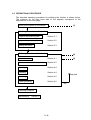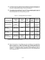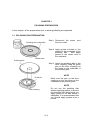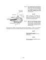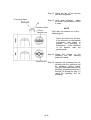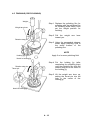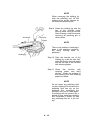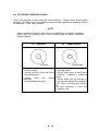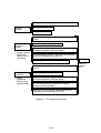
1
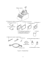
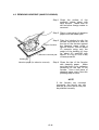
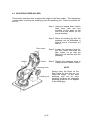
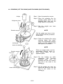
DOCUMENT NUMBER 39NPI-53E1-03
OFL-12 SERIES
OFL-126001
OFL-127001
MASS PRODUCTION POLISHER
INSTRUCTION MANUAL
Seiko Instruments Inc.
Components Sales Dept.
1-8, Nakase, Mihama-ku
Chiba-shi, Chiba-ken, 261, Japan
Telephone: 043-211-1211
Facsimile: 043-211-8030
DOCUMENT NUMBER 39NPI-53E1-03
OFL-12 SERIES
OFL-126001
OFL-127001
MASS PRODUCTION POLISHER
INSTRUCTION MANUAL
Seiko Instruments Inc.
Components Sales Dept.
1-8, Nakase, Mihama-ku
Chiba-shi, Chiba-ken, 261, Japan
Telephone: 043-211-1211
Facsimile: 043-211-8030
OFL-12 SERIES OFL-126001 OFL-127001 MASS PRODUCTION POLISHER
INSTRUCTION MANUAL
Document Number 39NPI-53E1-03
First Edition
March 1995
Second Edition November 1995
Third Edition March 1996
Copyright 1995, 1996 by Seiko Instruments Inc.
All rights reserved.
Seiko Instruments Inc. (SII) has prepared this manual for use by SII personnel,
licensees, and customers. The information contained herein is the property of SII
and shall not be reproduced in whole or in part without the prior written approval of
SII.
SII reserves the right to make changes without notice to the specifications and
materials contained herein and shall not be responsible for any damages (including
consequential) caused by reliance on the materials presented, including but not
limited to typographical, arithmetic, or listing errors.
SII
is a trademark of Seiko Instruments Inc.
Please address any questions, comments, and suggestions to:
Seiko Instruments USA Inc.
Seiko Instruments GmbH
Electronic Components Div.
2990 West Lomita Boulevard,
Torrance, CA 90505, U.S.A.
Telephone: 310-517-8113
Facsimile: 310-517-7792
OFC Div.
Siemensstra e 9,
63263 Neu-Isenburg, Germany
Telephone: 6102-2970
Facsimile: 6102-297222
Seiko Instruments (H.K.) Ltd.
Seiko Instruments Taiwan Inc.
Sales Dept.
45th Floor, Wyler Center 2, 200
Tai Lin Pai Road Kwai chung, N.T.,
Kowloon, Hong Kong.
Telephone: 852-421-8611
Facsimile: 852-480-5479
Sales Dept.
5f-1, No.99, Sec.2, Chung shan.Rd.,
Taipei 104, Taiwan, R.O.C
Telephone: 886-2-5635001, 5235111
Facsimile: 886-2-5219519
- ii -
PREFACE
This manual has been prepared to provide the information necessary to allow the
user to operate the OFL-12 Mass Production Polisher (hereafter referred to as OFL12) correctly and fully utilize its functions. Before using the OFL-12, be sure to read
this instruction manual thoroughly. Store the manual in a safe place for future
reference.
NOTE
The OFL-12 can only polish ferrules which meet the following conditions:
Ferrule material
Ferrule diameter
Zirconia (ZrO2)
2.5 mm (0.0984 inch)
The OFL-12 can polish ferrules after assembly only with ST-type
connectors. Please contact SII for options if you wish to polish almina
ceramic capillary ferrules, ferrules with different outer diameter, ferrules that
require flat, angled PC, or another style of polishing.
NOTE
The polishing film and polishing fluid used on the OFL-12 are selected
especially for the processes performed on the OFL-12. If you use any other
polishing film or fluid, we cannot guarantee that the polishing specifications
will be met.
- iii -
Before using the OFL-12, please make sure that all of the following items (shown in
figure 0-1) are present.
Table 0-1.
No
.
Part
Standard Parts
Part code
Qty.
OFL-12
1
Remarks
1
Basic machine
2
Holding jig
KJJ100101
1
for 2.5 mm dia.
3
Polishing disk
KJD100100
1
synthetic rubber
disk
4
Adhesive removal pad
KJO100101
1
with synthetic
rubber sheet
5
Polishing film (adhesive
removal)
(KJW100100
)
10*
Sheets
abrasive paper
6
Polishing film (grinding)
(KJW100200
)
1*
Sheet
green label
7
Polishing film (polishing)
(KJW100300
)
1*
Sheet
yellow label
8
Polishing film (finishing)
(KJW100400
)
1*
Sheet
white label
9
Polishing fluid
(KJA100100)
1*
100 ml
10
Squeezable dropper bottle
KJO100200
2
50 ml2
11
Power cord
KKO100420
1
12
Fuse
KKO100320
2
13
Ball-end hex wrench
KJO100500
1
14
Instruction manual
KKO100220
1
15
Soft brush
KJO101000
1
16
Setup Stand
KJO100600
1
17
Grease
KJO101200
1
18
Maintenance Manual
KKO100520
1
250 V, 1 A
* The quantity listed is the quantity included in the standard OFL-12 package. See
Table 0-2 for the quantities included in additional orders of individual items.
- iv -
➀ Basic machine
Polishing film (adhesive removal) (10)
Maintenance Manual
Adhesive removal pad
Holding jig (1)
Polishing disk (1)
Instruction Manual
Polishing film (grinding) (1)
Polishing film (polishing ) (1)
Polishing film (finishing) (1)
17) Ball-end hex wrench 16) Soft brush
15) Fuse (2)
11) Grease
13) Squeezable dropper bottle (2)
14) Setup stand
18) Power cord
Figure 0-1 Standard Parts
-v-
12) Polishing fluid (1 bottles)
The available consumable items are listed in Table 0-2.
Table 0-2 Consumable Items
Part
Polishing film (adhesive
removal)
Polishing film (grinding)
Polishing film (polishing)
Polishing film (finishing)
Polishing fluid
Standard consumable
supplies kit
Part code
Qty.
KJW10010
0
KJW10020
0
KJW10030
0
KJW10040
0
KJA100100
100
sheets
10
sheets
10
sheets
10
sheets
2
(100
ml
2)
1 set
KJS100100
Remarks
change after 1 use
change after 10 use
change after 10 use
change after 10 use
can polish approximately
600 ferrules per container
(12 ferrules at one time, 50
uses)
contents:
Polishing film
adhesive removal 100
grinding 10
polishing 10
finishing 10
Polishing fluid 2
The Standard Consumable Supplies Kit (part code 110-S-001) is sufficient to polish
about 1200 ferrules.
The available optional items are listed in Table 0-3.
Table 0-3 Options
Part
Part code
Qty.
Holding jig for D4
KJJ200100
1
Angled PC polishing set
(minimum set)
OFL-12 consumer
supplies kit for alumina
ceramic capillary ferrule
KJS100500
1 set
KJS100200
1 set
- vi -
Remarks
for zirconia capillary ferrule
(diameter:2.0mm (0.0787
inch))
for angled PC polishing
for alumina ceramic
capillary ferrule
TABLE OF CONTENTS
Section
Page
CHAPTER 1 USER NOTES
1.1 PRECAUTIONS FOR USING THE OFL-12 ................................................. 1-1
1.2 PREPARATION ........................................................................................... 1-1
1.3 PRECAUTIONS FOR USING POLISHING FLUID ...................................... 1-2
CHAPTER 2 OVERVIEW
2.1 PARTS NOMENCLATURE .......................................................................... 2-2
2.2 OPERATIONAL PROCEDURE.................................................................... 2-6
CHAPTER 3 POLISHING PREPARATION
3.1
3.2
3.3
3.4
POLISHING DISK PREPARATION ............................................................. 3-1
POLISHING FILM PREPARATION.............................................................. 3-2
THRUST (POLISHING PRESSURE) SETTING .......................................... 3-3
SETTING UP POLISHING TIME ................................................................. 3-4
CHAPTER 4 POLISHING PROCEDURE
4.1
4.2
4.3
4.4
4.5
4.6
MOUNTING THE FERRULES ..................................................................... 4-1
REMOVING ADHESIVE (HAND POLISHING) ............................................ 4-4
ADJUSTING FIBER HOLDER ..................................................................... 4-5
GRINDING (1ST POLISHING) AND POLISHING (2ND POLISHING)......... 4-6
FINISHING (3RD POLISHING) .................................................................... 4-10
POLISHING CONDITION CHECK ............................................................... 4-13
CHAPTER 5 MAINTENANCE
5.1 CLEANING AFTER POLISHING ................................................................. 5-1
5.2 CHANGING POLISHING FILM .................................................................... 5-1
- vii -
Section
Page
CHAPTER 6 TROUBLESHOOTING
APPENDIX
STANDARD POLISHING EFFICIENCY AND SPECIFICATIONS ............... A-1
- viii -
CHAPTER 1
USER NOTES
In this chapter, important notes for users are given. Please read them carefully
before using the OFL-12.
1.1 PRECAUTIONS FOR USING THE OFL-12
To protect the OFL-12 and use it correctly, please pay attention to the following
notes:
Do not leave the OFL-12 outdoors, or where water might damage it.
Do not subject the OFL-12 to undue vibrations or reckless drops.
Do not touch the operation panel or the switches with wet hands.
The OFL-12 is heavy (about 25 kg (55 lbs)), so place it on a sturdy table.
Be sure to supply electric power at the voltage and frequency specified.
Be sure to connect the grounding pin of the power cord plug to ground to
prevent electric shock.
Do not touch the rotating parts during use.
Be sure to disconnect the OFL-12 from the power source before changing the
polishing disks or other parts.
1.2 PREPARATION
In addition to the main Mass Production Polisher and its accessories, please
prepare the following items:
Cleaning paper
Ethyl alcohol
Water
Tap water
Washing container
3 (one for each polishing unit), approximately 3 (0.75
gal) each.(for washing the ferrules and holding jig)
lint-free synthetic cleaning tissue
1-1
1.3 PRECAUTIONS FOR USING POLISHING FLUID
Please pay attention to the following when using the polishing fluid:
If you get the polishing fluid on your skin or into your eyes, rinse with water
quickly and thoroughly.
Make sure the area where the polishing fluid is being used is well ventilated.
If the polishing fluid gets on your clothes, they should be washed thoroughly.
After using, seal the container and store in a place that is between 0 and
50C (32 and 122F).
1-2
CHAPTER 2
OVERVIEW
In this chapter, the parts of the OFL-12 basic machine and operational procedure
are explained.
In section 2.1, the names of the parts of the OFL-12 basic machine and their
function are explained.
In section 2.2, the standard operating procedure for polishing the ferrules is
explained.
2-1
2.1 PARTS NOMENCLATURE
The parts of the OFL-12 basic machine are explained in this section. Figure 2-1
shows the OFL-12 after the polishing disks have been installed on the machine.
Fiber holder
Weight arm
Fuse holder (2 places
Polishing disk
on the back side)
Protection cover
Timer
OFF button
POWER lamp
Power switch
Counter
ON button
Reset button (Counter)
Figure 2-1 External View of OFL-12 and Operating Panel
2-2
Power switch
Switches the power ON/OFF.
ON button (green)
When this button is pressed, the polishing disk begins to rotate. When the time
limit expires as set by the timer, the polishing disk stops rotating.
OFF button (red)
When this button is pressed, the polishing disk stops rotating and the polishing
operation stops immediately.
POWER lamp
Lights when power is input.
Timer
Specifies polishing time. The remaining time is displayed during polishing
operation.
Counter
The number of polishing operations can be checked on this counter. The
counter increments each time the ON button is pressed. To reset the counter,
press the reset button underneath the counter.
Fuse holder (2 places)
Holds a 250 V, 1 A fuse.
Fiber holder
The fibers are hung on this pole during polishing. The height is adjustable
according to the length of the fiber by loosening the black clamping knob,
slidingthe pole to the appropriate height, then tightening the knob.
Protection cover
When the cover is open, the polishing machine does not work if the switch is
turned on.
Polishing disk
Has a rubber disk on top onto which the polishing film is placed. The softness
ofthe rubber means that the tip of the ferrule will have a convex surface
polishedonto it.
2-3
11) Weight arm
Provides the correct polishing pressure to the ferrule tips.
setting positions for the weight on each arm.
There are three
12) Thrust pin
Applies the polishing pressure to the center of the holding jig so that a high
level of polishing can be obtained.
13) Rotation stop pin
Keeps the holding jig from rotating while the polishing disk is rotating.
2-4
Protection Cover
Protection covers are provided with this machine to prevent operator from
touching the moving parts.
Open the covers with the knobs. Each covers are fixed with magnets when
they are closed.
When the cover is open, the machine does not operate if the switch is turned
on.
Do not pinch your fingers when you open or close the covers.
Do not force the cover open.
If the cover is damaged, stop using the machine and contact your dealer.
Take care not to cut your hand on the damaged cover.
When the machine operates abnormally, for example, the machine operates
with the covers open, stop using the machine and contact your dealer.
2-5
2.2 OPERATIONAL PROCEDURE
The standard operating procedure for polishing the ferrules is shown below.
The numbers on the right hand side of the diagram correspond to the
explanations on the next page.
(1)
Check the condition of the ferrule
Polishing preparation
Section 3
Prepare the polishing disk
Section 3.1
Prepare the polishing film
Section 3.2
Setting the thrust
Section 3.3
Polishing procedure
Section 4
(2)
Mount ferrules
Section 4.1
Remove adhesive (hand polish)
Section 4.2
Grinding
Section 4.4
Polishing
Section 4.4
(3)
Repolish
Finishing
Section 4.5
Check polishing
Section 4.6
NG
Polishing complete
Maintenance
Section 5
2-6
(1) It is best to use only a small amount of adhesive on the tip of the ferrule. If
too much is used, sometimes it cannot be removed within the standard 30
seconds of hand polishing used to remove the adhesive.
(2) The polishing film, polishing fluid, and polishing conditions used in each of
the polishing steps are listed in Table 2-1. Refer to the details for each of
the polishing steps in the corresponding sections.
Table 2-1 Polishing Media and Conditions
Polishing
Film
Polishing
Fluid
Thrust1
(Std.)
Polishin
g Time
(Std.)
Adhesive removal
(hand polishing)
abrasive
paper
(KJW100100)
none
approx.
1 to 2 kg
(2.2 to
4.4 lbs)
30 sec.
dispose of
every time
(max. 12
ferrules)
Grinding
(1st polishing)
green label
(KJW100200)
water
Point 1
1 min.
30 sec.
10 times
(max. 120
ferrules)
Polishing
(2nd polishing)
yellow label
(KJW100300)
water
Point 2
1 min.
30 sec.
10 times
(max. 120
ferrules)
Finishing
(3rd polishing)
white label
(KJW100400)
Polishing
fluid
(KJA100100)
Point 2
1 min.
10 times
(max. 120
ferrules)
Polishing Step
1
Polishing
Film Life
The polishing thrust (pressure) varies according to the number of ferrules mounted in the holding
jig. Refer to section 3.3 for setting the thrust.
(3) Mount the ferrules in the holding jig evenly according to the explanation
given in section 4.1. When the ferrules are mounted incorrectly, the
ferrules can slip and the tips of the ferrules may not be polished correctly.
When mounting less than 12 ferrules in the holding jig, make sure they are
arranged in a balanced pattern, according to the explanation given in
section 4.1. An unbalanced arrangement of ferrules in the holding jig may
not be polished evenly.
2-7
2-8
CHAPTER 3
POLISHING PREPARATION
In this chapter, all the preparations prior to starting polishing are explained.
3.1 POLISHING DISK PREPARATION
Polishing disk (underside)
Step 1 Disconnect the power cord
from the outlet.
Step 2 Apply grease included in the
product to the underside of the
polishing disk.
Also apply
grease to the center hole of
the underside.
Grease here
Polishing disk
Step 3 Attach the polishing disk to the
drive coupling, fitting the guide
pins on the drive coupling into
the holes on the underside of
the polishing disk.
NOTE
Guide pin
Make sure the pins on the drive
coupling go into the holes on the
underside of the polishing disk.
NOTE
Do not use the polishing disk
without applying grease to prevent
the machine from being worn out.
Apply grease to the disk before it
dissipates. It is recommended that
you should apply grease once a
month.
Drive coupling
3-1
3.2 POLISHING FILM PREPARATION
Colored label
Step 1 Clean the rubber surface of the
polishing disk using cleaning
paper and ethyl alcohol. Be
sure to remove all dirt and
other foreign matter.
Step 2 Place the polishing film on the
polishing disk so it is centered.
With your hand, spread the
polishing film from the center
Rubber disk
outward to squeeze out the air.
Polishing film
Air
Polishing disk
Air
NOTE
Polishing film for Grinding:
Polishing film for Polishing:
Polishing film for Finishing:
3-2
Green label
Yellow label
White label
3.3 THRUST (POLISHING PRESSURE) SETTING
The polishing pressure (thrust) is set according to the polishing step and the number
of ferrules mounted in the holding jig. The polishing pressure is set by moving the
weight on the weight arm.
Step 1 Set the weight at one of the
three set positions for the
weight on the weight arm.
When you move the weight
along the weight arm, you can
feel the weight click at the set
positions.
Do not set the
weight inbetween the set
positions.
Weight arm
Point 3
Point 2
Weight
Point 1
Step 2 The weight set position to be
used depends on the polishing
set up and number of ferrules
mounted in the holding jig.
Refer to Table 3-1.
NOTE
If you have less than six ferrules
to polish, use dummy and/or
unusable ferrules so there are at
least six ferrules mounted in the
holding fixture. This is so that
the ferrules will get polished at
an equal quality level. Refer to
section 4.1.
Table 3-1 Weight Set Points
Weight Set Point
No. of
Mounted
Ferrules
Grinding
Polishing
Finishing
12
10
8
6
1
1
2
3
2
2
3
3
2
2
3
3
3-3
3.4 SETTING UP POLISHING TIME
SETUP PANEL
Remaining time display
Displays remaining polishing time
during polishing operation.
Setup time display
Displays the setup polishing time.
Polishing time setup keys
Sets up the polishing time.
Procedure of setting up polishint time
Press the polishing time setup keys to specify the polishing time. The
polishing time setup keys 1 through 4 correspond to each digit of the
setup time display.
m
key 4
key 3
S
key 2
key 1
Setup Time Display
Polishing time setup keys
Each time you press either of the polishing time setup keys, the
number of the corresponding digit increases by 1.
If you press “Reset”, “MODE”, or “DISPLAY” key, they do not function.
3-4
CHAPTER 4
POLISHING PROCEDURE
When all of the polishing preparations have been made, ferrule polishing can begin.
4.1 MOUNTING THE FERRULES
Step 1 Place the setup stand on a
desk or table and put the
holding jig onto the setup
stand, fitting the hole in the
holding jig onto the pin on the
setup stand.
V-grove
Ferrule
Step 2 Loosen the clamping screws
on the holding jig, turning
about 3 turns using the ballFerrule flange
end hex wrench.
Holding jig
Step 3 Place the ferrules into the Vgrooves in the holding jig. See
Clamping screw
Figure 4-1 for where to place
the ferrules to have a balanced
Ball-end hex wrench
pattern.
Step 4 On each side of the holding jig,
tighten the clamping screw with
the ball-end hex wrench while
lightly pushing the flange on
the ferrules against the holding
jig.
NOTE
To tighten the clamping screws
with the appropriate tightness,
tighten finger tight, then use the
ball-end hex wrench to tighten
one quarter turn more.
4-1
CAUTION
Make sure that the ferrules do
not move after clamping them in
the holding jig.
Dividing plane
Wire tie
Fiber
Ferrule
Step 5
Separate the fibers into two
bundles, one on each half of
the holding jig, and tie each
bundle with a wire tie.
NOTE
If you have less than six ferrules
to polish, use dummy or
unusable ferrules so there are at
least six ferrules mounted in the
holding fixture. This is so that
the ferrules will get polished at
an equal quality level.
Holding jig
Setup stand
4-2
12
1
1
11
2
10
10
9
3
9
(12)
(10)
6
5
6
6
8
1
7
1
2
5
(8)
6
4
7
5
7
3
8
4
8
2
(6)
4
3
5
2
: Ferrule
3
4
Figure 4-1 Balanced Ferrule Arrangements
Ferrule mounting is complete.
4-3
4.2 REMOVING ADHESIVE (HAND POLISHING)
Step 1 Clean the surface of the
synthetic rubber sheet with
ethyl alcohol. Make sure all
dirt and other foreign matter is
removed.
Step 2 Place a new piece of abrasive
paper onto the rubber pad.
Step 3 Take the holding jig with the
ferrules mounted in it and rub
the tips of the ferrules against
Figure-8 motion
the abrasive paper using a
figure-8 motion. Rub for about
10 seconds using only the
weight of the holding jig, then
for about 20 seconds with
Adhesive removal pad
about 1 to 2 kg (2.2 to 4.4 lbs)
of hand pressure.
Holding jig
Abrasive paper (for adhesive removal)
Step 4 Clean the tips of the ferrules
with cleaning paper.
Make
sure that there is no adhesive
remaining on the tips of the
ferrules. Use a new piece of
abrasive paper every time this
polishing step is done.
NOTE
If the ferrules are mounted
incorrectly, the ferrule can slip
and the tip of the ferrule may not
be polished correctly.
4-4
4.3 ADJUSTING FIBER HOLDER
This section describes how to adjust the height of the fiber holder. This adjustment
is done when mounting the holding jig onto the polishing unit. Refer to sections 4.4
and 4.5.
Step 1 Hang the looped fibers (which
have been tied into two
bundles) on the spool at the
end of the fiber holder (at the
lowest position).
Step 2 Mount the holding jig onto the
polishing unit as described in
steps 4 and 5 of sections 4.4
and 4.5.
Fiber holder
Weight
Fibers
Step 3 Loosen the clamping knob for
the fiber holder and slide the
fiber holder up so that the
fibers will not interfere with the
polishing.
Step 4 Tighten the clamping knob to
clamp the fiber holder in place.
Clamping knob
Polishing unit
4-5
NOTE
Always hang the fibers on the
fiber holder so that they do not
affect the weight. In this case
polishing may not be done
correctly because the adaquate
polishing pressure is not applied
to the holding jig.
4.4 GRINDING (1ST POLISHING) AND POLISHING (2ND POLISHING)
Step 1 Open the protection covers.
Weight
Step 2 Place the polishing film for
grinding (green label) on the
polishing disk, then set the
weight position for grinding.
Weight arm lever
Step 3 Pull the weight
toward you.
arm
lever
NOTE
Rotation stop pin
Set the weight arm lever to the
sown position with the protection
covers open.
Step 4 Clean the polishing film using
cleaning paper and water.
Using the squeezable dropper
bottle, wet the polishing film
with about 2 ml of water.
Holding jig
Notch in holding jig
NOTE
When you supply water, use the
squeezable dropper bottle to
avoid spilling water on the
operation panel.
Rotation stop pin
Thrust pin
Step 5 Put the holding jig (after
completing
the
previous
polishing step) onto the
polishing film with the rotation
stop pin in the notch in the
holding jig.
Step 6 Lift the weight arm lever up,
setting the thrust pin into the
hole in the center of the
holding jig.
Notch in holding jig
4-6
NOTE
Make sure that the weight arm
lever goes to the full up position.
If it does not, the correct
polishing pressure will not be
applied to the holding jig and
polishing will not be performed
correctly.
NOTE
Take care not to pinch your hand
with the weight when you attach
or detach the holding jig to or
from the machine.
Step 7 Close the protection covers.
Step 8 Set the timer to 1 min. 30 sec.
(standard).
Preparation for polishing is
complete.
Step 9 Press the ON button. The
polishing disk begins to rotate
and polishing begins.
NOTE
Press the OFF button if there is
any problem. The polishing disk
will stop rotating and polishing
will stop.
4-7
Step 10 The polishing will automatically
stop when the time set on the
timer is up. After the polishing
is completed, pull the weight
arm lever toward you and
remove the holding jig from the
polishing disk.
Soft brush
NOTE
Ferrule tip
Water
Holding jig
When removing the holding jig
from the polishing unit, lift the
holding jig up so the ferrules do
not touch the polishing film.
Step 11 Clean the holding jig and the
tips of the ferrules under
running water using the brush.
After cleaning, clean the brush,
removing all polishing grit or
other matter.
This illustration shows running water being used for washing. (There is no problem
if washing is done in the washing container, but using running water is preferred.)
NOTE
After cleaning, remove
waterdrops completely from the
holding jig.
NOTE
Do not touch the operation panel
with wet hands.
4-8
Step 12 Clean the tips of the ferrules
with cleaning paper.
Fluorescent lights
Step 13 (Only after grinding.) Make
sure that the polished surface
is clean.
Polished surface
Ferrule
Straight lines
NOTE
Don’t take the ferrules out of the
holding jig yet.
Check the ferrule tip surface.
If the reflection of two parallel
fluorescent light tubes is
parallel, the polishing is
satisfactory. If the reflection
is not parallel, redo the
grinding step.
Step 14 Clean the surface of the
polishing film with cleaning
paper and water.
Distorted lines
Step 15 Replace the polishing film for
grinding with the polishing film
for polishing (yellow label),
then set the weight position for
polishing. Repeat procedures 2
through 12 (except for step 11)
using the polishing film for
polishing.
4-9
4.5 FINISHING (3RD POLISHING)
Weight
Step 1 Replace the polishing film for
polishing with the polishing film
for finishing (white label), then
set the weight position for
finishing.
Weight arm lever
Step 2 Pull the weight
toward you.
arm
lever
Rotation stop pin
Step 3 Using the squeezable dropper
bottle, apply polishing fluid to
the entire surface of the
polishing film.
NOTE
Holding jig
Apply 2 ml or more polishing fluid
Notch in holding jig
Step 4 Put the holding jig (after
completing the polishing step)
onto the polishing film with the
rotation stop pin in the notch in
the holding jig.
Rotation stop pin
Thrust pin
Step 5 Lift the weight arm lever up,
setting the thrust pin into the
hole in the center of the
holding jig.
Notch in holding jig
4 - 10
NOTE
Make sure that the weight arm
lever goes to the full up position.
If it does not, the correct
polishing pressure will not be
applied to the holding jig and
polishing will not be performed
correctly.
Step 6 Set the timer to 1 min.
(standard).
Preparation for polishing is
complete.
NOTE
The first time a sheet of finishing
polishing film is used, the
polishing fluid will not completely
soak into the polishing film.
Therefore, when using a sheet of
finishing polishing film for the
first time, polish twice (1 minute
each).
Step 7 Press the ON button. The
polishing disk begins to rotate
and polishing begins.
NOTE
Press the OFF button if there is
any problem. The polishing disk
will stop rotating and polishing
will stop.
Step 8 The polishing will automatically
stop when the time set on the
timer is up. After the polishing
is completed, pull the weight
arm lever toward you and
remove the holding jig from the
polishing disk.
4 - 11
NOTE
When removing the holding jig
from the polishing unit, lift the
holding jig up so the ferrules do
not touch the polishing film.
Soft brush
Step 9 Clean the holding jig and the
tips of the ferrules under
running water using the brush.
After cleaning, clean the brush,
removing all polishing grit or
other matter.
Ferrule tip
Water
NOTE
There is no problem if washing is
done in the washing container,
but using running water is
preferred.
Holding jig
Step 10 Take the ferrules out of the
holding jig, undo the wire ties,
wash the ferrule tips with water
and dry the tips of the ferrules
with cleaning paper.
Step 11 Clean
the
ferrules
with
cleaning paper and ethyl
alcohol. Clean the surface of
the polishing film with cleaning
paper and water.
NOTE
Do not leave any polishing fluid
on the polishing film because the
polishing fluid can dry on the
polishing film, scratching the
ferrules if the film is used again.
If polishing will not be done for a
period of time, keep the polishing
film immersed in water so that
any polishing fluid on it will not
dry.
4 - 12
4.6 POLISHING CONDITION CHECK
Check the condition of the ferrule tips after polishing. If there was a deep scratch
caused in the fiber during the adhesive removal step, satisfactory polishing cannot
be obtained. In this case, repolish.
NOTE
When repolishing ferrules that have an unsatisfactory polished condition,
polish from the grinding step to the finishing step to obtain consistent
polished quality.
(1)
Speckles
(2)
Speckles
Repolish, doing the polishing and
finishing steps.
Occurs near the end of the life of
the polishing film.
when
the
ferrule
Occurs
mounting
in the holding jig is poor.
4 - 13
Slight Scratch
Slight scratch
Repolish, doing the polishing and
finishing steps.
Occurs when there is insufficient
cleaning
between
polishing
steps.
Occurs when you rub the tips of
the ferrules against the polishing
film when mounting the holding
jig
to and removing it from the
polishing unit.
(3)
Fiber Scratch or Large
Scratch
(4)
Polishing Fluid Remaining
Large scratch
Polishing fluid
Fiber scratch
Repolish, doing the grinding, Clean the tip of the ferrule. If you
polishing, and finishing steps.
cannot remove the polishing fluid,
do
the finishing step again.
Scratch was made during the
adhesive removal step.
Clean the ferrules carefully after
every polishing step.
Make sure you correctly follow
the
procedure for adhesive removal
(10 seconds with only the weight
of the jig, 20 seconds with 1 to 2
kg hand pressure).
4 - 14
CHAPTER 5
MAINTENANCE
In order that the machine functions correctly, the following maintenance operations
must be carried out after completion of polishing operations.
5.1 CLEANING AFTER POLISHING
After finishing polishing, or when stopping polishing for a period of time, clean
the OFL-12 as well as all of the polishing films carefully with water. If no
cleaning is done, the remaining polishing fluid will harden. Also make sure
that no waterdrops remain on the operation panel.
When the OFL-12 won’t be used for a long time, ultrasonically clean the
holding jig in ethyl alcohol, then oil the holding jig and keep it in a vinyl
envelope.
5.2 CHANGING THE POLISHING FILM
The standard lifetime of a sheet of polishing film is 10 uses (120 ferrules
maximum) (for the abrasive paper for adhesive removal the lifetime is only
one use).
5-1
5-2
CHAPTER 6
TROUBLESHOOTING
Figure 6-1 is a list of anticipated problems during machine operation along with
items to check. If a problem develops, refer to the appropriate section in Figure 6-1
to find what is out of the ordinary, and solve the problem. If the problem cannot be
solved, please contact SII.
6-1
Is the power cord plugged into a power outlet?
Doesn’t
operate
Is the timer set to 0?
Is the fuse blown?
Has the polishing film been used more than 10
times?
Can’t obtain
predome
shape
Speckles
Large scratch
End curve
radius out of
tolerance
Is water being used?
Is the surface of the polishing film being cleaned
with water between polishing steps?
Is the mounting correct: ferrules in the holding
jig and the holding jig on the unit?
Is the weight at the correct position?
Has the polishing film been used more than 10
times?
Bad surface
condition
Is polishing fluid being used?
Many
scratches
Return loss
below 40 dB
Is the surface of the polishing film being cleaned
with water between polishing steps?
Are the ferrules being cleaned with water
between polishing steps?
Was the tip of the ferrule rubbed on the film
when being removed from the unit?
Figure 6-1 Troubleshooting Chart
6-2
Repolish
Refer to
section
4.6
APPENDIX
STANDARD POLISHING EFFICIENCY AND SPECIFICATIONS
Applicable EC Directives & Standards
Directives
89/392/EEC
89/336/EEC
Standards
Machinery:
EMC:
Title
Machinery
Electromagnetic Compatibility
EN292-1 (1991)
EN292-2 (1991)
EN294 (1992)
EN418 (1992)
EN60204-1 (1992)
EN55022 (1987 and 1994) / Class B
EN50082-1 (1992)
IEC801-2 (1984)
IEC801-3 (1984)
IEC801-4 (1988)
Standard polishing efficiency (R20 convex surface polishing) :
Standard polishing time (excluding adhesive removal)
Grinding
1.5 minutes
Polishing
1.5 minutes
Finishing
1.0 minutes
Polishing process
3 steps (excluding adhesive removal)
Return loss
40 dB or more
End curve radius
10 to 25 mm (0.394 to 0.984 inch)
End curve offset
50 m (0.00197 inch) or less
Fiber under-cut
0.1 m or less
Noise
60 dB (A) or less
General specifications:
Power supply
Power consumption
Operating temperature
Physical dimensions
Weight
Timer
220/230 VAC, 50/60 Hz (OFL-126001)
230/240 VAC, 50/60 Hz (OFL-127001)
55 W
10 to 40C (50 to 104F) (noncondensing)
240 (W)390 (D)530 (H) mm
(9.4515.420.5 inches)
(with fiber holder at the lowest position)
approximately 25 kg (55 lbs)
0 through 99 min. 59 sec. (Unit: second)
A-1
Operating environmental specifications :
Operating temperature
Relative humidity
Vibration
Acceptable impact
10 to 40C (50 to 104F) (noncondensing)
15% to 85%
operating: 0.25 G 5 to 100 Hz 10min.
powered-off: 0.50 G 5 to 100 Hz 20min.
50 mm (1.97 inch) drop (one side)
Storing environmental specifications :
Storing temperature
Relative humidity
-25 to 65C (8 to 149F) (noncondensing)
15% to 85%
A-2