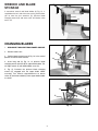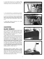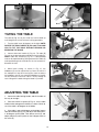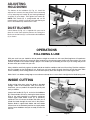
1
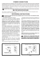
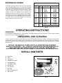
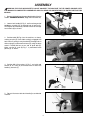
(Model SS200)
PART NO. 905591 - 05-31-02
Copyright © 2002 Delta Machinery
To learn more about DELTA MACHINERY
visit our website at: www.deltamachinery.com.
For Parts, Service, Warranty or other Assistance,
please call
ESPAÑOL: PÁGINA 15
1-800-223-7278 (In Canada call 1-800-463-3582).
INSTRUCTION MANUAL
16" Scroll Saw
GENERAL SAFETY RULES
Woodworking can be dangerous if safe and proper operating procedures are not followed. As with all machinery, there
are certain hazards involved with the operation of the product. Using the machine with respect and caution will
considerably lessen the possibility of personal injury. However, if normal safety precautions are overlooked or ignored,
personal injury to the operator may result. Safety equipment such as guards, push sticks, hold-downs, featherboards,
goggles, dust masks and hearing protection can reduce your potential for injury. But even the best guard won’t make
up for poor judgment, carelessness or inattention. Always use common sense and exercise caution in the workshop.
If a procedure feels dangerous, don’t try it. Figure out an alternative procedure that feels safer. REMEMBER: Your
personal safety is your responsibility.
This machine was designed for certain applications only. Delta Machinery strongly recommends that this machine not
be modified and/or used for any application other than that for which it was designed. If you have any questions relative
to a particular application, DO NOT use the machine until you have first contacted Delta to determine if it can or should
be performed on the product.
Technical Service Manager
Delta Machinery
4825 Highway 45 North
Jackson, TN 38305
(IN CANADA: 505 SOUTHGATE DRIVE, GUELPH, ONTARIO N1H 6M7)
WARNING: FAILURE TO FOLLOW THESE RULES MAY RESULT IN SERIOUS PERSONAL INJURY
1. FOR YOUR OWN SAFETY, READ INSTRUCTION
MANUAL BEFORE OPERATING THE TOOL. Learn the
tool’s application and limitations as well as the specific
hazards peculiar to it.
2. KEEP GUARDS IN PLACE and in working order.
3. ALWAYS WEAR EYE PROTECTION. Wear safety
glasses. Everyday eyeglasses only have impact resistant
lenses; they are not safety glasses. Also use face or dust
mask if cutting operation is dusty. These safety glasses
must conform to ANSI Z87.1 requirements. NOTE:
Approved glasses have Z87 printed or stamped on them.
4. REMOVE ADJUSTING KEYS AND WRENCHES. Form
habit of checking to see that keys and adjusting wrenches
are removed from tool before turning it “on”.
5. KEEP WORK AREA CLEAN. Cluttered areas and
benches invite accidents.
6. DON’T USE IN DANGEROUS ENVIRONMENT. Don’t
use power tools in damp or wet locations, or expose them
to rain. Keep work area well-lighted.
7. KEEP CHILDREN AND VISITORS AWAY. All children
and visitors should be kept a safe distance from work area.
8. MAKE WORKSHOP CHILDPROOF – with padlocks,
master switches, or by removing starter keys.
9. DON’T FORCE TOOL. It will do the job better and be
safer at the rate for which it was designed.
10. USE RIGHT TOOL. Don’t force tool or attachment to
do a job for which it was not designed.
11. WEAR PROPER APPAREL. No loose clothing, gloves,
neckties, rings, bracelets, or other jewelry to get caught in
moving parts. Nonslip footwear is recommended. Wear
protective hair covering to contain long hair.
12. SECURE WORK. Use clamps or a vise to hold work
when practical. It’s safer than using your hand and frees
both hands to operate tool.
13. DON’T OVERREACH. Keep proper footing and
balance at all times.
14. MAINTAIN TOOLS IN TOP CONDITION. Keep tools
sharp and clean for best and safest performance. Follow
instructions for lubricating and changing accessories.
15. DISCONNECT TOOLS before servicing and when
changing accessories such as blades, bits, cutters, etc.
16. USE RECOMMENDED ACCESSORIES. The use of
accessories and attachments not recommended by Delta
may cause hazards or risk of injury to persons.
17. REDUCE THE RISK OF UNINTENTIONAL STARTING.
Make sure switch is in “OFF” position before plugging in
power cord. In the event of a power failure, move switch
to the “OFF” position.
18. NEVER STAND ON TOOL. Serious injury could occur if
the tool is tipped or if the cutting tool is accidentally
contacted.
19. CHECK DAMAGED PARTS. Before further use of the
tool, a guard or other part that is damaged should be
carefully checked to ensure that it will operate properly and
perform its intended function – check for alignment of
moving parts, binding of moving parts, breakage of parts,
mounting, and any other conditions that may affect its
operation. A guard or other part that is damaged should be
properly repaired or replaced.
20. DIRECTION OF FEED. Feed work into a blade or
cutter against the direction of rotation of the blade or cutter
only.
21. NEVER LEAVE TOOL RUNNING UNATTENDED.
TURN POWER OFF. Don’t leave tool until it comes to a
complete stop.
22. STAY ALERT, WATCH WHAT YOU ARE DOING, AND
USE COMMON SENSE WHEN OPERATING A POWER
TOOL. DO NOT USE TOOL WHILE TIRED OR UNDER
THE INFLUENCE OF DRUGS, ALCOHOL, OR
MEDICATION. A moment of inattention while operating
power tools may result in serious personal injury.
23. MAKE SURE TOOL IS DISCONNECTED FROM
P O W E R S U P P LY w h i l e m o t o r i s b e i n g m o u n t e d ,
connected or reconnected.
24. THE DUST GENERATED by certain woods and wood
products can be injurious to your health. Always operate
machinery in well ventilated areas and provide for proper
dust removal. Use wood dust collection systems whenever
possible.
25.
WARNING: SOME DUST CREATED BY
POWER SANDING, SAWING, GRINDING, DRILLING,
AND OTHER CONSTRUCTION ACTIVITIES contains
chemicals known to cause cancer, birth defects or other
reproductive harm. Some examples of these chemicals
are:
· lead from lead-based paints,
· crystalline silica from bricks and cement and other
masonry products, and
· arsenic and chromium from chemically-treated lumber.
Your risk from these exposures varies, depending on how
often you do this type of work. To reduce your exposure
to these chemicals: work in a well ventilated area, and
work with approved safety equipment, such as those
dust masks that are specially designed to filter out
microscopic particles.
SAVE THESE INSTRUCTIONS.
Refer to them often and use them to instruct others.
2
ADDITIONAL SAFETY RULES FOR
SCROLL SAWS
WARNING: FAILURE TO FOLLOW THESE RULES MAY RESULT IN SERIOUS PERSONAL INJURY.
1. DO NOT OPERATE THIS MACHINE until it is
assembled and installed according to the instructions.
2. OBTAIN ADVICE FROM YOUR SUPERVISOR,
instructor, or another qualified person if you are not
familiar with the operation of this machine.
3. FOLLOW ALL WIRING CODES and recommended
electrical connections.
4. YOUR SCROLL SAW MUST be securely fastened
to a stand or workbench. If there is any tendency for the
stand or workbench to move during operation, the stand
or workbench MUST be fastened to the floor.
5. THIS SCROLL SAW is intended for indoor use only.
6. MAKE SURE blade is properly tensioned before
operating saw.
7. TO AVOID blade breakage ALWAYS adjust blade
tension correctly.
8. MAKE SURE the blade teeth point downward
toward the table.
9. NEVER turn the saw "ON" before clearing the table
of all objects (tools, scraps of wood, etc.).
10. DO NOT cut material that is too small to be safely
supported.
11. AVOID awkward hand positions where a sudden slip
could cause a hand to move into the blade.
12. ALWAYS keep hands and fingers away from blade.
13. ALWAYS adjust holddown foot for each new
operation.
14. DO NOT USE dull or bent blades.
15. DO NOT attempt to saw material that does not have
a flat surface, unless a suitable support is used.
16. MAKE "relief" cuts before cutting long curves.
17. NEVER attempt to cut a curve that is too tight for
the blade being used.
18. WHEN backing a blade out of a workpiece, the
blade may bind in the saw kerf. This is usually caused by
sawdust in the kerf. If this happens, turn "OFF" the
switch and remove plug from power source outlet.
Wedge open the kerf and back blade out of the
workpiece.
19. THE USE of attachments and accessories not
recommended by Delta may result in the risk of injuries.
20. ALWAYS hold the work firmly against the table.
21. DO NOT feed the material too fast while cutting.
Only feed the material fast enough so that the blade will
cut.
22. NEVER start the Scroll Saw with the stock pressed
against the blade.
23. WHEN cutting a large workpiece MAKE SURE the
material is supported at table height.
24. USE CAUTION when cutting material which is
irregular in cross section which could pinch the blade
before the cut is completed. A piece of moulding for
example must lay flat on the table and not be permitted
to rock while being cut.
25. USE CAUTION when cutting round material such as
dowel rods or tubing. They have a tendency to roll while
being cut causing the blade to "bite." Use a V-block to
control the piece.
26. ALWAYS release blade tension before removing the
blade from the upper or lower blade holders.
27. MAKE CERTAIN table tilting lock is tightened
before starting the machine.
28. NEVER reach under the table while the machine is
running.
29. NEVER perform layout, assembly or set-up work on
the table while the saw is operating.
30. ALWAYS STOP the saw before removing scrap
pieces from the table.
31. TURN THE MACHINE “OFF” AND DISCONNECT
THE MACHINE from the power source before installing
or removing accessories, before adjusting or changing
set-ups, or when making repairs.
32. TURN THE MACHINE “OFF”, disconnect the
machine from the power source, and clean the
table/work area before leaving the machine. LOCK THE
SWITCH IN THE “OFF” POSITION to prevent
unauthorized use.
33. ADDITIONAL INFORMATION regarding the safe
and proper operation of this tool is available from the
Power Tool Institute, 1300 Summer Avenue, Cleveland,
OH 44115-2851. Information is also available from the
National Safety Council, 1121 Spring Lake Drive, Itasca,
IL 60143-3201. Please refer to the American National
Standards Institute ANSI 01.1 Safety Requirements for
Woodworking Machines and the U.S. Department of
Labor OSHA 1910.213 Regulations.
SAVE THESE INSTRUCTIONS.
Refer to them often
and use them to instruct others.
3
POWER CONNECTIONS
A separate electrical circuit should be used for your machines. This circuit should not be less than #12 wire and should
be protected with a 20 Amp time lag fuse. If an extension cord is used, use only 3-wire extension cords which have 3prong grounding type plugs and matching receptacle which will accept the machine’s plug. Before connecting the
motor to the power line, make sure the switch is in the “OFF” position and be sure that the electric current is of the
same characteristics as indicated on the machine. All line connections should make good contact. Running on low
voltage will damage the motor.
WARNING: DO NOT EXPOSE THE MACHINE TO RAIN OR OPERATE THE MACHINE IN DAMP LOCATIONS.
MOTOR SPECIFICATIONS
Your machine is wired for 120 volt, 60 HZ alternating current. Before connecting the machine to the power source,
make sure the switch is in the “OFF” position.
GROUNDING INSTRUCTIONS
WARNING: THIS MACHINE MUST BE GROUNDED WHILE IN USE TO PROTECT THE OPERATOR FROM
ELECTRIC SHOCK.
1. All grounded, cord-connected machines:
2. Grounded, cord-connected machines intended for use
on a supply circuit having a nominal rating less than 150
In the event of a malfunction or breakdown, grounding
volts:
provides a path of least resistance for electric current to
reduce the risk of electric shock. This machine is
If the machine is intended for use on a circuit that has an
equipped with an electric cord having an equipmentoutlet that looks like the one illustrated in Fig. A, the
grounding conductor and a grounding plug. The plug must
machine will have a grounding plug that looks like the plug
be plugged into a matching outlet that is properly installed
illustrated in Fig. A. A temporary adapter, which looks like
and grounded in accordance with all local codes and
the adapter illustrated in Fig. B, may be used to connect
ordinances.
this plug to a matching 2-conductor receptacle as shown
in Fig. B if a properly grounded outlet is not available. The
Do not modify the plug provided - if it will not fit the outlet,
temporary adapter should be used only until a properly
have the proper outlet installed by a qualified electrician.
grounded outlet can be installed by a qualified electrician.
Improper connection of the equipment-grounding
The green-colored rigid ear, lug, and the like, extending
conductor can result in risk of electric shock. The
from the adapter must be connected to a permanent
conductor with insulation having an outer surface that is
ground such as a properly grounded outlet box. Whenever
green with or without yellow stripes is the equipmentthe adapter is used, it must be held in place with a metal
grounding conductor. If repair or replacement of the
screw.
electric cord or plug is necessary, do not connect the
equipment-grounding conductor to a live terminal.
NOTE: In Canada, the use of a temporary adapter is not
permitted by the Canadian Electric Code.
Check with a qualified electrician or service personnel if
t h e g ro u n d i n g i n s t r u c t i o n s a re n o t c o m p l e t e l y
understood, or if in doubt as to whether the machine is
WARNING: IN ALL CASES, MAKE CERTAIN THE
properly grounded.
RECEPTACLE IN QUESTION IS PROPERLY
G R O U N D E D . I F Y O U A R E N O T S U R E H AV E A
Use only 3-wire extension cords that have 3-prong
QUALIFIED ELECTRICIAN CHECK THE RECEPTACLE.
grounding type plugs and matching 3-conductor
receptacles that accept the machine’s plug, as shown in
Fig. A.
Repair or replace damaged or worn cord immediately.
GROUNDED OUTLET BOX
GROUNDED OUTLET BOX
GROUNDING
MEANS
CURRENT
CARRYING
PRONGS
ADAPTER
GROUNDING BLADE
IS LONGEST OF THE 3 BLADES
Fig. A
4
Fig. B
EXTENSION CORDS
MINIMUM GAUGE EXTENSION CORD
RECOMMENDED SIZES FOR USE WITH STATIONARY ELECTRIC MACHINES
Use proper extension cords. Make sure your extension
cord is in good condition and is a 3-wire extension cord
which has a 3-prong grounding type plug and matching
receptacle which will accept the machine’s plug. When
using an extension cord, be sure to use one heavy
enough to carry the current of the machine. An
undersized cord will cause a drop in line voltage,
resulting in loss of power and overheating. Fig. D, shows
the correct gauge to use depending on the cord length.
If in doubt, use the next heavier gauge. The smaller the
gauge number, the heavier the cord.
Ampere
Rating
Volts
Total Length
of Cord in Feet
Gauge of
Extension Cord
0-6
0-6
0-6
0-6
120
120
120
120
up to 25
25-50
50-100
100-150
18 AWG
16 AWG
16 AWG
14 AWG
6-10
6-10
6-10
6-10
120
120
120
120
up to 25
25-50
50-100
100-150
18 AWG
16 AWG
14 AWG
12 AWG
10-12
10-12
10-12
10-12
120
120
120
120
up to 25
25-50
50-100
100-150
16 AWG
16 AWG
14 AWG
12 AWG
12-16
12-16
12-16
120
120
120
up to 25
25-50
14 AWG
12 AWG
GREATER THAN 50 FEET NOT RECOMMENDED
Fig. D
FOREWORD
OPERATING INSTRUCTIONS
Delta ShopMaster Model SS200 is a 16" Scroll Saw. The Model SS200 comes with a powerful 1.8 amp., induction motor
for long lasting, and smooth performance.
UNPACKING AND CLEANING
Carefully unpack the machine and all loose items from the shipping container(s). Remove the protective coating from
all unpainted surfaces. This coating may be removed with a soft cloth moistened with kerosene (do not use acetone,
gasoline or lacquer thinner for this purpose). After cleaning, cover the unpainted surfaces with a good quality household
floor paste wax.
NOTICE: THE MANUAL COVER PHOTO ILLUSTRATES THE CURRENT
PRODUCTION MODEL. ALL OTHER ILLUSTRATIONS ARE REPRESENTATIVE
ONLY AND MAY NOT DEPICT THE ACTUAL COLOR, LABELING OR
ACCESSORIES AND MAY BE INTENDED TO ILLUSTRATE TECHNIQUE ONLY.
SCROLL SAW PARTS
A
B
C
D
E
F
G
H
I
-
Scroll Saw
Table
Table Insert
Holddown Assembly
Quickset Wrench
Table Lock Handle
6mm Wrench
4mm Wrench
Pivot Bolt
I
A
J
K
D
B
C
E
J - M6.4 Flat Washers (2)
K - M6 Hex Nut
F
Fig. 4
5
G
H
ASSEMBLY
WARNING: FOR YOUR OWN SAFETY, DO NOT CONNECT THE MACHINE TO THE POWER SOURCE UNTIL
THE MACHINE IS COMPLETELY ASSEMBLED AND YOU READ AND UNDERSTAND THE ENTIRE INSTRUCTION
MANUAL.
D
1. Remove the blade from the upper blade holder. (See the
section “CHANGING BLADES”, begin with instruction #3).
K
L
2. Loosen lock handle (K) Fig. 5, and insert long end of
holddown assembly (D) up through hole in bracket (L).
Then tighten lock handle (K). Connect end of air hose (M)
to air nozzle (N) as shown.
N
M
Fig. 5
3. Position table (B) Fig. 6, on the machine, as shown,
making sure pin (O) in rear table casting is engaged with
hole in base casting. Insert pivot bolt (E) through hole in
table casting (P) and thread into base (Q) using the 6mm
wrench. Thread M6 hex nut on end of pivot bolt (E).
Make sure the tilt scale (R) Fig. 7, is positioned inside
pointer (S) as shown.
O
B
E
P
Q
Fig. 6
4. Position M6.4 flat washers (J) Fig. 7, on inside and
outside of tilt scale (R) and thread end of table lock
handle (I) into hole (T).
R
I
T
S
J
Fig. 7
5. Figure 8 illustrates table lock handle (I) assembled to
machine.
I
Fig. 8
6
6. Re-attach blade to upper blade holder. (See the
section “CHANGING BLADES”, begin with instruction
#6).
7. Assemble table insert (C) Fig. 9, in table as shown.
NOTE: Opening in table insert (C) should be positioned
toward the front for normal work with the table in the
level position and should be positioned toward the right
when tilting the table.
C
FASTENING SCROLL SAW
TO SUPPORTING SURFACE
Fig. 9
This scroll saw MUST be securely fastened to a stand or
workbench using the three holes, two of which are
shown at (A) Fig. 10. The third hole is at the rear of the
machine.
An alternate method of securing the scroll saw to a supporting surface is to fasten the scroll saw to a mounting
board. Then securely clamp the mounting board to a
stand or workbench using two or more C-clamps. NOTE:
For proper stability, the holes in the mounting board
must be countersunk at the bottom so that the fastener
heads are flush with the bottom surface of the mounting
board.
A
Fig. 10
OPERATING CONTROLS AND ADJUSTMENTS
ON-OFF SWITCH
The on-off switch (A) Fig. 11, is located on the motor
directly under the right hand side of the table. To turn the
saw “ON”, move the switch (A) up to the “ON” position.
To turn the saw “OFF”, move the switch down to the
“OFF” position.
A
LOCKING SWITCH IN THE
“OFF” POSITION
Fig. 11
IMPORTANT: When the machine is not in use, the switch
should be locked in the OFF position to prevent
unauthorized use. This can be done by grasping the
switch toggle (B) and pulling it out of the switch, as
shown in Fig. 12. With the switch toggle (B) removed,
the switch will not operate. However, should the switch
toggle be removed while the saw is running, the switch
can be turned “OFF” once, but cannot be restarted
without inserting the switch toggle (B).
B
Fig. 12
7
WRENCH AND BLADE
STORAGE
A convenient wrench and blade holder (A) Fig. 13, is
supplied on the left side of the rear casting, which allows
you to store the hex wrenches (C), quickset blade
changing wrench (B) and extra scroll saw blades when
not in use.
B
C
A
Fig. 13
CHANGING BLADES
1. DISCONNECT MACHINE FROM POWER SOURCE.
2. Remove table insert.
B
3. Position blade tension lever (A) Fig. 19, in the vertical
position to release blade tension.
A
D
4. Insert long end (A) Fig. 14, of quickset blade
changing wrench into hole (B) in upper blade holder. This
will align wrench (C) with blade holder screw (D).
C
5. Fig. 15, illustrates the quickset blade changing
wrench (E) engaged with the upper blade holder
assembly. Turn wrench counterclockwise to loosen
screw (D) and remove blade (F) from upper blade holder
as shown.
Fig. 14
D
E
F
Fig. 15
8
6. Insert long end (A) Fig. 16, of quickset blade
changing wrench into hole (G) in lower blade holder. This
will help align wrench (C) with blade holder screw (H).
C
H
G
A
Fig. 16
7. Turn wrench (E) Fig. 17, counterclockwise to loosen
screw (H) and remove blade (F) from lower blade holder.
8. Insert new blade into the lower and upper blade
holders in the same manner, making certain the blade
teeth are pointing down toward the table. Tighten screws
in both the upper and lower blade holders. Replace table
insert.
F
H
E
9. Apply blade tension by referring to the section
“ADJUSTING BLADE TENSION”.
Fig. 17
ADJUSTING
BLADE TENSION
Tension is applied to the blade when the blade tension
lever (A) Fig. 18, has been adjusted and is in the
horizontal position as shown. When the blade tension
lever (A) is moved to the vertical position, as shown in
Fig. 19, blade tension is released.
A
To adjust blade tension, position lever (A) in the vertical
position, as shown in Fig. 19. To increase tension, turn
lever (A) clockwise and to decrease tension turn lever (A)
counterclockwise. When adjusting tension, turn lever
one-quarter of a turn at a time. NOTE: It is necessary to
adjust the blade tension only when the blade is removed
from both the upper and lower blade holders and a new
or different type of blade is assembled to the holders. It
is not necessary to adjust blade tension when the blade
is removed and replaced in only the upper blade holder
as in performing inside cutting operations. After desired
tension is obtained, position tension lever (A) in the
horizontal position, as shown in Fig. 18.
Fig. 18
A
Adjusting the blade for proper tension is usually
accomplished by trial and error. One method is to pull
back on the blade tension lever (A) Fig. 19, the blade
should start to have tension (resistance) when the blade
tension lever is half way between open Fig. 19, and
closed Fig. 18. Finer blades require more tensioning
while thicker blades require less tension.
Fig. 19
9
B
B
A
Fig. 20
Fig. 20A
TILTING THE TABLE
The table (A) Fig. 20, on your scroll saw can be tilted up
to 45 degrees to the left for bevel cutting operations.
D
1. Turn the table insert 90 degrees to the right. NOTE:
ROTATE THE TABLE INSERT (B) FIG. 20A, TO ALLOW
YOU TO TILT THE TABLE WITHOUT BENDING OR
BREAKING THE BLADE.
C
2. Loosen table lock handle (A) Fig. 20. Tilt table (B)
Fig. 20, to the desired angle and tighten lock handle (A).
NOTE: Table lock handle (A) Fig. 20, is spring-loaded
and can be repositioned by pulling outward on handle (A)
and repositioning hub of handle on the nut located underneath the hub.
Fig. 21
3. When bevel cutting, as shown in Fig. 21, the
holddown (C) can be adjusted to lay flat on the stock. If
the workpiece is too thick causing the stock to contact
the holddown arm (D), the complete holddown assembly
can be removed, since thick stock is heavy enough to
resist lifting off the table during the blade’s up stroke.
A
Fig. 22
ADJUSTING THE TABLE
B
1. Loosen the table locking handle, and tilt the table all
the way to the right.
2. Place one end of a square (A) Fig. 22, on the table
and the other end against the blade, as shown. Check to
see if the table is 90 degrees to the blade.
E
3. If the table is not at 90 degrees to the blade, loosen
table lock handle (B) Fig. 23, and adjust the table until it
is 90 degrees to the blade. Then loosen screw (C) and
adjust pointer (D) until it points to the 0 degree mark on
the scale (E).
D
C
Fig. 23
10
ADJUSTING
HOLDDOWN
B
The bottom of the holddown (A) Fig. 24, should be
adjusted so it contacts the top surface of the work being
cut by loosening lock handle (B) and moving holddown
assembly (C) up or down. Then tighten lock handle (B).
NOTE: Lock handle (B) is spring-loaded and can be
repositioned by pulling out handle and repositioning on
the nut located directly underneath the hub.
D
C
DUST BLOWER
A dust blower (D) Fig. 24, is supplied with your saw to
direct air to the most effective point on the cutting line.
Make sure end of hose (D) is connected to the holddown
(A) as shown.
A
Fig. 24
OPERATIONS
FOLLOWING A LINE
With your scroll saw you should be able to perform straight or curved cuts with ease. Most beginners will experience
blade wandering; however, they eventually learn to control it as they become more familiar with the machine. Use scrap
material to practice cuts before starting a project. This enables you to develop your own style of cutting and you will
discover what you can do with your saw.
Always hold the work firmly against the table and do not feed the workpiece too fast while cutting. Feed the workpiece
only fast enough so that the blade will cut. Scroll saws cut faster across the grain than they do with the grain. Allow
for this tendency when cutting patterns that shift rather quickly from with-the-grain cuts to cross-grain cuts.
Make "relief" cuts before cutting long curves and never attempt to cut a curve that is too tight for the blade being used.
INSIDE CUTTING
C
Inside cutting takes place when the blade is threaded
through a hole in the workpiece. With your Delta 16”
Scroll Saw, you can perform this operation quickly and
easily as follows:
A
Loosen lock handle (A) Fig. 25, and raise the holddown
(B). Release blade tension by moving the blade tension
lever to the vertical position as previously explained.
Loosen upper blade holder screw (C) as previously
explained. This will release the blade and allow you to
thread the blade through the next hole in the pattern.
Replace blade in upper blade holder and move blade
tension lever to the horizontal position to re-apply blade
tension. Lower holddown and you are ready to make the
next cut.
B
Fig. 25
11
MAINTENANCE
LUBRICATION
Perform maintenance below after each 20 hours of use.
1. DISCONNECT MACHINE FROM POWER SOURCE.
2. Remove the four screws (A) Fig. 26, and side panel
(B).
3. Release blade tension by moving blade tension lever
to the vertical position.
B
A
4. Remove the two pivot bolts and wave washers (C)
Fig. 27.
5. Fig. 28 illustrates one of the pivot bolts and wave
washers (C) removed. Thoroughly clean grease from
shafts of both pivot bolts and lubricate shafts with a few
drops of light machine oil.
6. Re-assemble the two pivot bolts and replace side
panel. Re-apply tension to the blade.
Fig. 26
C
Fig. 27
C
Fig. 28
12
A
CHOICE OF BLADES
Your scroll saw will accept a wide variety of 5" flat end blades. Consider the following as a general guideline for
selecting a blades.
1.
2.
3.
4.
Use a finer blade for cutting thin workpieces, for hard materials, or when a smooth cut is required.
Use a coarser blade for cutting thick workpieces, when making straight cuts or for medium to soft materials.
Use a blade that will have 2 teeth in the workpiece at all times.
Most blade packaging is marked with the size of the wood the blade is intended to cut and the minimum radius
which can be cut with that blade.
BLADE BREAKAGE
Blade breakage is usually caused by one or more of the following:
1. Bending the blade during installation.
2. Improper blade tension.
3. Improper blade selection for the work being cut.
4. Forcing the work into the blade too rapidly.
5. Cutting too sharp a turn for the blade being used.
13
ACCESSORIES
A complete line of accessories is available from your Delta Supplier, Porter-Cable • Delta Factory Service Centers,
and Delta Authorized Service Stations. Please visit our Web Site www.deltamachinery.com for a catalog or
for the name of your nearest supplier.
WARNING: Since accessories other than those offered by Delta have not been tested
with this product, use of such accessories could be hazardous. For safest operation, only
Delta recommended accessories should be used with this product.
PARTS, SERVICE OR WARRANTY ASSISTANCE
All Delta Machines and accessories are manufactured to high quality standards and are serviced by a network
of Porter-Cable • Delta Factory Service Centers and Delta Authorized Service Stations. To obtain additional
information regarding your Delta quality product or to obtain parts, service, warranty assistance, or the location
of the nearest service outlet, please call 1-800-223-7278 (In Canada call 1-800-463-3582).
Two Year Limited Warranty
Delta will repair or replace, at its expense and at its option, any Delta machine, machine part, or machine accessory which
in normal use has proven to be defective in workmanship or material, provided that the customer returns the product
prepaid to a Delta factory service center or authorized service station with proof of purchase of the product within two
years and provides Delta with reasonable opportunity to verify the alleged defect by inspection. Delta may require that
electric motors be returned prepaid to a motor manufacturer’s authorized station for inspection and repair or replacement.
Delta will not be responsible for any asserted defect which has resulted from normal wear, misuse, abuse or repair or
alteration made or specifically authorized by anyone other than an authorized Delta service facility or representative. Under
no circumstances will Delta be liable for incidental or consequential damages resulting from defective products. This
warranty is Delta’s sole warranty and sets forth the customer’s exclusive remedy, with respect to defective products; all
other warranties, express or implied, whether of merchantability, fitness for purpose, or otherwise, are expressly
disclaimed by Delta.
Printed in U.S.A.
14