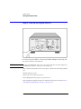
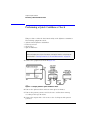
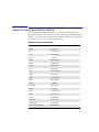
1
Agilent 83433A
Lightwave Transmitter
User’s Guide
© Copyright
Agilent Technologies 2000
All Rights Reserved. Reproduction, adaptation, or translation without prior written
permission is prohibited,
except as allowed under copyright laws.
Agilent Part No. 83433-90001
Printed in USA
February 2000
Agilent Technologies
Lightwave Division
1400 Fountaingrove Parkway
Santa Rosa, CA 95403-1799,
USA
(707) 577-1400
Notice.
The information contained in
this document is subject to
change without notice. Companies, names, and data used
in examples herein are fictitious unless otherwise noted.
Agilent Technologies makes
no warranty of any kind with
regard to this material, including but not limited to, the
implied warranties of merchantability and fitness for a
particular purpose. Agilent
Technologies shall not be liable for errors contained herein
or for incidental or consequential damages in connection with the furnishing,
performance, or use of this
material.
Restricted Rights Legend.
Use, duplication, or disclosure by the U.S. Government
is subject to restrictions as set
forth in subparagraph (c) (1)
(ii) of the Rights in Technical
Data and Computer Software
clause at DFARS 252.227-7013
for DOD agencies, and subparagraphs (c) (1) and (c) (2)
of the Commercial Computer
Software Restricted Rights
clause at FAR 52.227-19 for
other agencies.
Warranty.
This Agilent Technologies
instrument product is warranted against defects in
material and workmanship for
a period of one year from date
of shipment. During the warranty period, Agilent Technologies will, at its option, either
repair or replace products
which prove to be defective.
For warranty service or repair,
this product must be returned
to a service facility designated by Agilent Technologies. Buyer shall prepay
shipping charges to Agilent
Technologies and Agilent
Technologies shall pay shipping charges to return the
product to Buyer. However,
Buyer shall pay all shipping
charges, duties, and taxes for
products returned to Agilent
Technologies from another
country.
Agilent Technologies warrants that its software and
firmware designated by Agilent Technologies for use with
an instrument will execute its
programming instructions
when properly installed on
that instrument. Agilent Technologies does not warrant that
the operation of the instrument, or software, or firmware
will be uninterrupted or errorfree.
Limitation of Warranty.
The foregoing warranty shall
not apply to defects resulting
from improper or inadequate
maintenance by Buyer, Buyersupplied software or interfacing, unauthorized modification or misuse, operation
outside of the environmental
specifications for the product,
or improper site preparation
or maintenance.
No other warranty is
expressed or implied. Agilent
Technologies specifically disclaims the implied warranties
of merchantability and fitness
for a particular purpose.
Exclusive Remedies.
The remedies provided herein
are buyer's sole and exclusive
remedies. Agilent Technolo-
ii
❍ The OFF symbols
are used to mark the
positions of the instrument power line
switch.
gies shall not be liable for any
direct, indirect, special, incidental, or consequential damages, whether based on
contract, tort, or any other
legal theory.
The CE mark is a registered trademark of
the European Community.
Safety Symbols.
CAUTION
The caution sign denotes a
hazard. It calls attention to a
procedure which, if not correctly performed or adhered
to, could result in damage to
or destruction of the product.
Do not proceed beyond a caution sign until the indicated
conditions are fully understood and met.
The CSA mark is a registered trademark of
the Canadian Standards Association.
The C-Tick mark is a
registered trademark
of the Australian Spectrum Management
Agency.
WARNING
The warning sign denotes a
hazard. It calls attention to a
procedure which, if not correctly performed or adhered
to, could result in injury or
loss of life. Do not proceed
beyond a warning sign until
the indicated conditions are
fully understood and met.
The instruction manual symbol. The product is marked with this
warning symbol when
it is necessary for the
user to refer to the
instructions in the
manual.
The laser radiation
symbol. This warning
symbol is marked on
products which have a
laser output.
The AC symbol is used
to indicate the
required nature of the
line module input
power.
| The ON symbols are
used to mark the positions of the instrument
power line switch.
ISM1-A
This text denotes the
instrument is an
Industrial Scientific
and Medical Group 1
Class A product.
Typographical Conventions.
The following conventions are
used in this book:
Key type for keys or text
located on the keyboard or
instrument.
Softkey type for key names that
are displayed on the instrument’s screen.
Display type for words or
characters displayed on the
computer’s screen or instrument’s display.
User type for words or charac-
ters that you type or enter.
Emphasis type for words or
characters that emphasize
some point or that are used as
place holders for text that you
type.
General Safety Considerations
General Safety Considerations
This product has been designed and tested in accordance with IEC Publication 61010-1, Safety Requirements for Electrical Equipment for Measurement,
Control, and Laboratory Use, and has been supplied in a safe condition. The
instruction documentation contains information and warnings that must be
followed by the user to ensure safe operation and to maintain the product in a
safe condition.
WARNING
If this instrument is not used as specified, the protection provided by
the equipment could be impaired. This instrument must be used in a
normal condition (in which all means for protection are intact) only.
WARNING
To prevent electrical shock, disconnect the Agilent 83433A from
mains before cleaning. Use a dry cloth or one slightly dampened with
water to clean the external case parts. Do not attempt to clean
internally.
WARNING
This is a Safety Class 1 product (provided with a protective earthing
ground incorporated in the power cord). The mains plug shall only be
inserted in a socket outlet provided with a protective earth contact.
Any interruption of the protective conductor inside or outside of the
product is likely to make the product dangerous. Intentional
interruption is prohibited.
WARNING
No operator serviceable parts inside. Refer servicing to qualified
personnel. To prevent electrical shock, do not remove covers.
WARNING
Do not, under any circumstances, look into the optical output or any
fiber/device attached to the output while the laser is in operation.
WARNING
Do not enable the laser when no fiber or equivalent device is attached
to the OPTICAL OUTPUT connector.
WARNING
For continued protection against fire hazard, replace line fuse only
with same type and ratings (5x20 mm,1.6 A, 250 V time-delay, low
braking capacity fuse). The use of other fuses or materials is
prohibited.
iii
General Safety Considerations
CAUTION
This product is designed for use in Installation Category II and Pollution
Degree 2 per IEC 61010-1 and 664 respectively.
CAUTION
VENTILATION REQUIREMENTS: When installing the product in a cabinet, the
convection into and out of the product must not be restricted. The ambient
temperature (outside the cabinet) must be less than the maximum operating
temperature of the product by 4°C for every 100 watts dissipated in the
cabinet. If the total power dissipated in the cabinet is greater than 800 watts,
then forced convection must be used.
CAUTION
Always use the three-prong ac power cord supplied with this instrument.
Failure to ensure adequate earth grounding by not using this cord may cause
instrument damage.
CAUTION
Do not connect ac power until you have verified the line voltage is correct as
described in “GENERAL SPECIFICATIONS” on page 4-3. Damage to the
equipment could result.
CAUTION
This instrument has autoranging line voltage input. Be sure the supply voltage
is within the specified range.
Measurement accuracy—it’s up to you!
Fiber-optic connectors are easily damaged when connected to dirty or damaged cables
and accessories. The Agilent 83433A front-panel OPTICAL INPUT connector is no exception. When you use improper cleaning and handling techniques, you risk expensive
instrument repairs, damaged cables, and compromised measurements.
Before you connect any fiber-optic cable to the Agilent 83433A, refer to “Cleaning Connections for Accurate Measurements” on page 3-6.
iv
General Safety Considerations
Laser classification
The Agilent 83433A is classified as an IEC LASER Class 3B according to
IEC 825-1:1999-11, and an FDA LASER class 3B according to 21CFR 1040.10. The total
power of light energy radiated out of the LASER OUT connector is 8.5 to 11 dBm. Operator precautions are necessary to maintain safety. The Agilent 83433A contains no user
serviceable parts. Removal of covers may result in hazardous radiation exposure.
v
The Agilent 83433A—At a Glance
The Agilent 83433A—At a Glance
The Agilent 83433A lightwave transmitter is based on a lithium niobate modulator driven by an internal CW DFB 1552.52 nm laser. The laser and modulator
are inter-connected externally with a PMF fiber. The modulator can also be
used with an external laser with polarization maintaining fiber such as the Agilent 8164A, with 81680A option 071.
The Agilent 83433A is designed to produce high fidelity, low jitter waveforms
for 2.488 Gb/s STM-16/OC-48, 9.953 Gb/s STM-64/OC-192 and other transmission rates up through 10.7 Gb/s. The Agilent 83433A is intended for BER testing with error performance analyzers such as the Agilent 71612B. The MachZehnder modulator is adjusted for a fixed zero chirp. Its output waveform produces a minimum extinction ratio of 12 dB.
The internal DFB laser can be modulated at frequencies from 15 kHz to
10 MHz to increase linewidth for SBS suppression or channel identification
applications. The internal laser wavelength can be adjusted ±1.25 nm around
the 1552.52 center wavelength.
The Agilent 83433A can be combined with the Agilent 83434A 10 Gb/s lightwave receiver to create a complete optical link for system or fiber testing, or to
form a basis for substitution testing of commercial transmitters and receivers.
vi
Contents
The Agilent 83433A—At a Glance vi
1 Getting Started
2 Using the Agilent 83433A
Front-Panel Features 2-2
Rear-Panel Features 2-4
Using a Laser Source 2-5
Performing a Quick Confidence Check 2-6
Connecting the Agilent 83433A to a Bit-Error-Ratio Test Set 2-9
Connecting the Agilent 83433A to an Oscilloscope 2-11
3 Reference
Options 3-2
Replacement Parts 3-3
Front-Panel Fiber-Optic Adapters 3-4
Power Cords 3-5
Cleaning Connections for Accurate Measurements 3-6
Returning the Instrument for Service 3-17
Agilent Technologies Service Offices 3-20
4 Specifications and Regulatory Information
Agilent 83433A Specifications and Characteristics 4-3
Regulatory Information 4-6
Contents-1
1
Step 1. Inspect the Shipment 1-3
Step 2. Check the Fuse 1-5
Step 3. Connect the Line-Power Cable 1-6
Step 4. Turn on the Agilent 83433A 1-8
Step 5. Avoid costly repairs 1-9
Step 6. Learn more about our products 1-10
Getting Started
Getting Started
Setting Up the Agilent 83433A
Setting Up the Agilent 83433A
The instructions in this chapter show you how to install your lightwave transmitter. After you’ve completed this chapter, continue with Chapter 2, “Using
the Agilent 83433A”. Refer to Chapter 3, “Reference” for the following additional information:
• Tips on avoiding costly repairs by proper optical connection cleaning
techniques.
• Lists of available accessories and power cords.
• Instructions on returning your instrument to Agilent Technologies for service.
• Agilent Technologies Sales and Service Offices.
Chapter 4, “Specifications and Regulatory Information” contains information
on operating conditions, such as temperature.
1-2
Getting Started
Setting Up the Agilent 83433A
Step 1. Inspect the Shipment
NOTE
The Agilent 83433A is supplied with an optical jumper cable. To avoid costly
replacement, do not misplace this cable.
❒ Inspect the shipping container for damage.
❒ Inspect the instrument.
❒ Verify that you received the options and accessories you ordered.
Keep the shipping container and cushioning material until you have inspected
the contents of the shipment for completeness and have checked the lightwave transmitter mechanically and electrically.
The lightwave transmitter is packed within a carton. Refer to “Returning the
Instrument for Service” on page 3-16, for the description and part numbers of
the packaging materials. Refer to “Options” on page 3-2, for the accessories
shipped with the lightwave transmitter.
If the shipping materials are in good condition, retain them for possible future
use. You may wish to ship the lightwave transmitter to another location or
return it to Agilent Technologies for service. Refer to “Returning the Instrument for Service” on page 3-16.
1-3
Getting Started
Setting Up the Agilent 83433A
If anything is missing or defective, or if the lightwave transmitter does not
pass the verification test, contact your nearest Agilent Technologies Sales
Office. If the shipment was damaged, contact the carrier, then contact the
nearest Agilent Technologies Sales Office. Keep the shipping materials for the
carrier’s inspection. The Agilent Sales Office will arrange for repair or replacement at Agilent Technologies’ option without waiting for claim settlement.
Serial numbers
Agilent Technologies makes frequent improvements to its products to
enhance their performance, usability, or reliability, and to control costs. Agilent service personnel have access to complete records of design changes to
each type of equipment, based on the equipment’s serial number. Whenever
you contact Agilent about your lightwave transmitter, have the complete serial
number available to ensure obtaining the most complete and accurate information possible.
A serial-number label is attached to the rear of the lightwave transmitter. It
contains the serial number and the options installed in the lightwave transmitter. Whenever you specify the serial number or refer to it in obtaining information about your lightwave transmitter, be sure to use the complete number.
1-4
Getting Started
Setting Up the Agilent 83433A
Step 2. Check the Fuse
1 Locate the line-input connector on the instrument’s rear panel.
2 Disconnect the line-power cable if it is connected.
3 Use a small flat-blade screwdriver to pry open the fuse holder door.
4 The fuse is housed in a small container. Insert the tip of a screwdriver on the
side of the container and gently pull outward to remove the container. A spare
fuse is stored below the line fuse.
WARNING
For continued protection against fire hazard, replace line fuse only
with same type and ratings (5×20 mm,1.6 A, 250 V time-delay, low
breaking capacity fuse). The use of other fuses or materials is
prohibited.
1-5
Getting Started
Setting Up the Agilent 83433A
Step 3. Connect the Line-Power Cable
CAUTION
Always use the three-prong AC power cord supplied with this instrument.
Failure to ensure adequate earth grounding by not using this cord may cause
instrument damage.
CAUTION
Do not connect ac power until you have verified the line voltage is correct as
described in the following paragraphs. Damage to the equipment could result.
CAUTION
This instrument has autoranging line voltage input. Be sure the supply voltage
is within the specified range.
1 Verify that the line power meets the requirements shown in the following table.
Line Power Requirements
Power
1-6
115 VAC: 50 WATTS MAX
230 VAC: 50 WATTS MAX
Getting Started
Setting Up the Agilent 83433A
Line Power Requirements
Voltage
Frequency
nominal: 115 VAC
range: 90–132 V
nominal: 230 VAC
range: 98–254 V
nominal: 50 Hz/60 Hz
range: 47–63 Hz
2 Connect the line-power cord to the rear-panel connector of the instrument.
3 Connect the other end of the line-power cord to the power receptacle.
Various power cables are available to connect the Agilent 83433A to ac power
outlets unique to specific geographic areas. The cable appropriate for the area
to which the Agilent 83433A is originally shipped is included with the unit. You
can order additional ac power cables for use in different geographic areas.
Refer to “Power Cords” on page 3-5.
1-7
Getting Started
Setting Up the Agilent 83433A
Step 4. Turn on the Agilent 83433A
• Press the front-panel LINE key. All front-panel LED’s will light momentarily. The
line power indicator will remain lit.
NOTE
The front panel LINE switch disconnects the mains circuit from the mains supply after
the EMC filters and before other parts of the instrument.
If the Agilent 83433A fails to turn on properly, consider the following possibilities:
❒ Is the line fuse good?
❒ Does the line socket have power?
❒ Is it plugged into the proper ac power source?
If the instrument still fails, return it to Agilent Technologies for repair. Refer to
“Returning the Instrument for Service” on page 3-17.
1-8
Getting Started
Setting Up the Agilent 83433A
Step 5. Avoid costly repairs
CAUTION
Fiber-optic connectors are easily damaged when connected to dirty or
damaged cables and accessories. The front-panel connectors of the
Agilent 83433A are no exception. When you use improper cleaning and
handling techniques, you risk expensive instrument repairs, damaged cables,
and compromised measurements. Before you connect any fiber-optic cable to
the Agilent 83433A, refer to “Cleaning Connections for Accurate
Measurements” on page 3-6.
CAUTION
For proper operation without an external laser, connect the supplied optical
jumper cable between the EXTERNAL LASER INPUT and the CLASS IIIB
INTERNAL LASER OUT. Be sure to position the LASER ENABLE key in the off
position before making any connection. Agilent recommends the use of Panda
PMF fiber with the EXTERNAL LASER INPUT.
1-9
Getting Started
Setting Up the Agilent 83433A
Step 6. Learn more about our products
To learn more about this or any Agilent Technologies product, visit our website at http://www.agilent.com.
To learn more about Fiber Optic Test Equipment, go to the Agilent Technologies home page listed above, and follow this path:
1 Click Products.
2 Click Test and Measurement.
3 Under Products, click Fiber Optic Test Equipment.
This path will take you to the Fiber Optic Test Equipment page.
Or you can enter the URL for this page directly:
http://www.tm.agilent.com/tmo/Products/English/FiberOpticTestEquipment.html
1-10
2
Front-Panel Features 2-2
Rear-Panel Features 2-4
Using a Laser Source 2-5
Performing a Quick Confidence Check 2-6
Connecting the Agilent 83433A to a Bit-Error-Ratio Test Set 2-9
Connecting the Agilent 83433A to an Oscilloscope 2-11
Using the Agilent 83433A
Using the Agilent 83433A
Front-Panel Features
Front-Panel Features
LASER ENABLE
This key disables the Internal Class IIIB laser
when in the OFF position. Be sure this key is in
the OFF position before making or removing any
optical connections.
DATA INPUT
Modulation input for digital signals. The input is
AC coupled.
DATA PRESENT INDICATOR
Lights when LASER ENABLE is ON and valid
data is present.
WAVELENGTH ADJUST
Allows you to adjust the laser’s wavelength when
the variable mode is activated. Press the WAVELENGTH ADJUST ENABLE button so that the frontpanel light turns on.
2-2
Using the Agilent 83433A
Front-Panel Features
WAVELENGTH ADJUST ENABLE Toggles between preset laser wavelength and
wavelength adjust mode. (Light turns on to indicate you can adjust the setting using the knob.).
OPTICAL OUT
Provides the modulated optical output for the
instrument. A universal adapter is used that can
be removed and replaced with different adapters
as needed (refer to “Front-Panel Fiber-Optic
Adapters” on page 3-4).
CLASS IIIB INTERNAL LASER OUT Provides the internal laser output for the instrument. Use only Panda PMF fiber with this output. Use the supplied optical jumper cable to
connect this connector to the EXTERNAL
LASER INPUT.
EXTERNAL LASER INPUT
LOW FREQUENCY
MODULATION INPUT
Enables connection of external lasers with
Panda PMF output connectors to the internal
optical modulator.
BNC connector which allows direct, low-frequency modulation of the internal laser.
2-3
Using the Agilent 83433A
Rear-Panel Features
Rear-Panel Features
2-4
Using the Agilent 83433A
Using a Laser Source
Using a Laser Source
The Agilent 83433A contains an IEC LASER Class 3B according to IEC 60825.
The total power of light energy radiated out of the LASER OUT connector is
8.5 to 11 dBm. Use caution when making or breaking connections to the front
panel.
Three safety mechanisms are provided:
• A laser safety shutter over the front-panel CLASS IIIB INTERNAL LASER OUT connector. This shutter must be opened when attaching or removing cables.
• A key switch on the front panel must be turned on to enable the laser. When
this key is turned on, the front-panel LED next to the key will light.
• A REMOTE SHUTDOWN connector on the rear panel. This connector must
be shorted for the laser to operate. When the short is removed from the connector, the accessible radiation does not exceed the AEL for FDA Laser
Class 1 (IEC Laser Class 1) according to IEC publication CE/IEC 8211: 1993. Use your own short, switch, or other circuitry to control the REMOTE SHUTDOWN.
To enable the laser, follow these three steps:
1 Make sure a short is connected to the rear panel REMOTE SHUTDOWN
connector. The laser will not operate without the short connected.
2 Insert the key into the transmitter’s front panel.
3 Turn the key to turn the laser source on.
WARNING
Do not, under any circumstances, look into the optical output or any
fiber/device attached to the output while the laser is in operation.
WARNING
Do not enable the laser when no fiber or equivalent device is attached
to the OPTICAL OUTPUT connector.
2-5
Using the Agilent 83433A
Performing a Quick Confidence Check
Performing a Quick Confidence Check
This procedure verifies the basic functionality of the lightwave transmitter.
The following equipment is used:
•
•
•
•
Agilent 83433A lightwave transmitter
Pattern generator
Clock source
Optical multimeter
Note
Before starting be sure to clean all connectors and optical interfaces using the procedures describe in “Cleaning Connections for Accurate Measurements” on page 3-6.
1 Connect the equipment as shown in Figure 2-1.
Figure 2-1. Setup to perform a quick confidence check.
2 Turn on the Agilent 83433A and let it warm up for 30 minutes.
3 Turn on the pattern generator and clock source and let them warm up
according to their specifications.
4 Connect the output of the clock source to the clock input of the pattern
generator.
2-6
Using the Agilent 83433A
Performing a Quick Confidence Check
5 Connect the data output of the pattern generator to the DATA INPUT of the
83433A.
6 Use the ruggedized optical cable with Panda polarization maintaining fiber to
connect the 83433A CLASS IIIB INTERNAL LASER OUTPUT to the EXTENAL LASER
INPUT.
7 Connect the 83433A CLASS I OPTICAL OUT to the input of an optical multimeter.
8 Set the pattern generator as follows:
Clock output frequency . . . . . . . . . . . . . . . . . . . . . . . . . . . . . . . 9953.28 MHz
Data output . . . . . . . . . . . . . . . . . . . . . . . . . . . . . . . . . . . External AC coupled
Data amplitude . . . . . . . . . . . . . . . . . . . . . . . . . . . . . . . . . . . . . . . . . . . . . 1.0 V
Pattern. . . . . . . . . . . . . . . . . . . . . . . . . . . . . . . . . . . . . . . . . . . . . . 231 –1 PRBS
9 On the 83433A, ensure the wavelength adjust feature is disabled (front-panel
LED is off).
10 Turn the LASER ENABLE key to the ON position.
11 Measure the optical power at the output of the 83433A. It will show a minimum
of zero dBm.
2-7
Using the Agilent 83433A
Performing a Quick Confidence Check
If the verification check fails
If the lightwave transmitter does not pass the verification check, you should
review the procedure being performed when the problem occurred. A few
minutes spent performing some simple checks may save waiting for your
instrument to be repaired. Before calling Agilent Technologies or returning
the unit for service, please make the following checks:
1 Is the line fuse good?
2 Does the line socket have power?
3 Is the unit plugged in to the proper ac power source?
4 Is the unit turned on? Verify the green light-emitting diode (LED) next to the
line switch is on, indicating that the power supply is on.
5 If other equipment, cables, and connectors are being used with the lightwave
transmitter, are they connected properly and operating correctly?
6 Review the procedure for the test being performed when the problem
appeared. Are all the settings correct?
7 Are the connectors clean? Refer to“Cleaning Connectors” on page 3-12 for
more information about cleaning the connectors.
If the lightwave transmitter still fails, you can:
Return the lightwave transmitter to Agilent Technologies for repair. If the
lightwave transmitter is still under warranty or is covered by an Agilent Technologies maintenance contract, it will be repaired under the terms of the warranty or contract (the warranty is at the front of this manual). If the lightwave
transmitter is no longer under warranty or is not covered by an Agilent Technologies maintenance plan, Agilent Technologies will notify you of the cost of
the repair after examining the unit. Refer to “Returning the Instrument for
Service” on page 3-16 for more information.
WARNING
No operator serviceable parts inside. Refer servicing to qualified
personnel. To prevent electrical shock do not remove covers.
2-8
Using the Agilent 83433A
Connecting the Agilent 83433A to a Bit-Error-Ratio Test Set
Connecting the Agilent 83433A to a
Bit-Error-Ratio Test Set
The following procedure describes how to connect the lightwave transmitter
to a bit-error-ratio test set (BERT). The following equipment is used:
•
•
•
•
Agilent 83433A lightwave transmitter
Lightwave receiver or Agilent 83434A
Bit error ratio tester or Agilent 71612B error performance analyzer
Optical attenuator
1 Connect the equipment as shown in Figure 2-2.
2-9
Using the Agilent 83433A
Connecting the Agilent 83433A to a Bit-Error-Ratio Test Set
Figure 2-2. Connecting the Agilent 83433A to a bit-error-ratio test system.
2 Use the optical cable with Panda polarization maintaining fiber to connect the
Agilent 83433A CLASS IIIb INTERNAL LASER output to the EXTERNAL LASER INPUT.
3 Adjust the optical attenuator so the power to the receiver is between 0 dBm
and –16 dBm.
2-10
Using the Agilent 83433A
Connecting the Agilent 83433A to an Oscilloscope
Connecting the Agilent 83433A to an
Oscilloscope
The following procedure describes how to connect the lightwave transmitter
to an oscilloscope. The following equipment is used:
•
•
•
•
•
Agilent 83433A lightwave transmitter
Pattern generator
Clock source
Optical multimeter
Optical oscilloscope
Note
Before starting, be sure to clean all connectors and optical interfaces using the procedures describe in “Cleaning Connections for Accurate Measurements” on page 3-6.
1 Follow the procedure described in “Performing a Quick Confidence Check” on
page 2-6.
2 After completing this check, connect the OPTICAL OUTPUT of the Agilent 83433A
to the optical input of the oscilloscope.
3 Connect the trigger output of the pattern generator to the trigger input of the
oscilloscope.
4 Evaluate the OPTICAL OUTPUT of the Agilent 83433A with the OC-192/STM-64
filters and eye mask selected.
2-11
3
Options 3-2
Replacement Parts 3-3
Front-Panel Fiber-Optic Adapters 3-4
Power Cords 3-5
Cleaning Connections for Accurate Measurements
Returning the Instrument for Service 3-17
Agilent Technologies Service Offices 3-20
Reference
3-6
Reference
Options
Options
Accessories supplied
The Agilent 83433A lightwave transmitter is shipped with:
• FC/PC connector adapter on the optical output of the lightwave transmitter
unless a different option was ordered. Refer to Table 3-1, “Agilent 83433A
Options,” on page 3-2 for a complete list of the available connector interfaces.
• Optical jumper cable, Agilent part number 5022-1843.
• Agilent 83433A Lightwave Receiver User’s Guide, Agilent part number
83434-90001.
Available
seperately
The Fiber Optics Handbook, Agilent part number 5952-9654, is an introduction and reference for fiber-optic measurements.
Options
Table 3-1. Agilent 83433A Options
Option
Description
Option 011
Diamond (HMS-10) connector interface on
the optical output of the lightwave
transmitter
Option 013
DIN connector interface on the optical
output of the lightwave transmitter
Option 014
ST connector interface on the optical
output of the lightwave transmitter
Option 017
SC connector interface on the optical
output of the lightwave transmitter
3-2
Reference
Replacement Parts
Replacement Parts
Table 3-2. Replaceable Parts
Description
Agilent Part Nmmber
APC 3.5 F-to-F (connector saver)
5061-5311
APC 3.5 50 ohm termination
1810-0118
Optical jumper cable
5022-1843
FC/PC connector interface
81000FI
3-3
Reference
Front-Panel Fiber-Optic Adapters
Front-Panel Fiber-Optic Adapters
Front Panel
Fiber-Optic
Adapter
Description
Agilent Part Number
Diamond HMS-10
81000AI
FC/PCa
81000FI
D4
81000GI
SC
81000KI
DIN
81000SI
ST
81000VI
Biconic
81000WI
Dust Covers
FC connector
1005-0594
Diamond HMS-10 connector
1005-0593
DIN connector
1005-0595
ST connector
1005-0596
SC connector
1005-0597
a. The FC/PC adapter is the standard adapter supplied with the instrument.
3-4
Reference
Power Cords
Power Cords
Plug Type
Cable Part No.
Plug Description
Length
(in/cm)
Color
Country
250V
8120-1351
8120-1703
Straight *BS1363A
90°
90/228
90/228
Gray
Mint Gray
United Kingdom,
Cyprus, Nigeria, Zimbabwe, Singapore
250V
8120-1369
Straight *NZSS198/ASC
90°
79/200
Gray
Australia, New Zealand
87/221
Mint Gray
8120-0696
250V
8120-1689
8120-1692
8120-2857p
Straight *CEE7-Y11
90°
Straight (Shielded)
79/200
79/200
79/200
Mint Gray
Mint Gray
Coco Brown
East and West Europe,
Saudi Arabia, So.
Africa, India (unpolarized in many nations)
125V
8120-1378
8120-1521
8120-1992
Straight *NEMA5-15P
90°
Straight (Medical) UL544
90/228
90/228
96/244
Jade Gray
Jade Gray
Black
United States, Canada,
Mexico, Philippines,
Taiwan
250V
8120-2104
8120-2296
Straight *SEV1011
1959-24507
Type 12 90°
79/200
79/200
Mint Gray
Mint Gray
Switzerland
220V
8120-2956
8120-2957
Straight *DHCK107
90°
79/200
79/200
Mint Gray
Mint Gray
Denmark
250V
8120-4211
8120-4600
Straight SABS164
90°
79/200
79/200
Jade Gray
Republic of South
Africa
India
100V
8120-4753
8120-4754
Straight MITI
90°
90/230
90/230
Dark Gray
Japan
* Part number shown for plug is the industry identifier for the plug only. Number shown for cable is the Agilent
Technologies part number for the complete cable including the plug.
3-5
Reference
Cleaning Connections for Accurate Measurements
Cleaning Connections for Accurate Measurements
Today, advances in measurement capabilities make connectors and connection techniques more important than ever. Damage to the connectors on calibration and verification devices, test ports, cables, and other devices can
degrade measurement accuracy and damage instruments. Replacing a damaged connector can cost thousands of dollars, not to mention lost time! This
expense can be avoided by observing the simple precautions presented in this
book. This book also contains a brief list of tips for caring for electrical connectors.
Choosing the Right Connector
A critical but often overlooked factor in making a good lightwave measurement is the selection of the fiber-optic connector. The differences in connector types are mainly in the mechanical assembly that holds the ferrule in
position against another identical ferrule. Connectors also vary in the polish,
curve, and concentricity of the core within the cladding. Mating one style of
cable to another requires an adapter. Agilent Technologies offers adapters for
most instruments to allow testing with many different cables. Figure 3-1 on
page 3-7 shows the basic components of a typical connectors.
The system tolerance for reflection and insertion loss must be known when
selecting a connector from the wide variety of currently available connectors.
Some items to consider when selecting a connector are:
• How much insertion loss can be allowed?
• Will the connector need to make multiple connections? Some connectors are better than others, and some are very poor for making repeated connections.
• What is the reflection tolerance? Can the system take reflection degradation?
• Is an instrument-grade connector with a precision core alignment required?
• Is repeatability tolerance for reflection and loss important? Do your specifications
take repeatability uncertainty into account?
• Will a connector degrade the return loss too much, or will a fusion splice be required? For example, many DFB lasers cannot operate with reflections from connectors. Often as much as 90 dB isolation is needed.
3-6
Reference
Cleaning Connections for Accurate Measurements
Figure 3-1. Basic components of a connector.
Over the last few years, the FC/PC style connector has emerged as the most
popular connector for fiber-optic applications. While not the highest performing connector, it represents a good compromise between performance, reliability, and cost. If properly maintained and cleaned, this connector can
withstand many repeated connections.
However, many instrument specifications require tighter tolerances than most
connectors, including the FC/PC style, can deliver. These instruments cannot
tolerate connectors with the large non-concentricities of the fiber common
with ceramic style ferrules. When tighter alignment is required, Agilent
Technologies instruments typically use a connector such as the Diamond
HMS-10, which has concentric tolerances within a few tenths of a micron. Agilent Technologies then uses a special universal adapter, which allows other
cable types to mate with this precision connector. See Figure 3-2.
Figure 3-2. Universal adapters to Diamond HMS-10.
3-7
Reference
Cleaning Connections for Accurate Measurements
The HMS-10 encases the fiber within a soft nickel silver (Cu/Ni/Zn) center
which is surrounded by a tough tungsten carbide casing, as shown in
Figure 3-3.
Figure 3-3. Cross-section of the Diamond HMS-10 connector.
The nickel silver allows an active centering process that permits the glass fiber
to be moved to the desired position. This process first stakes the soft nickel
silver to fix the fiber in a near-center location, then uses a post-active staking
to shift the fiber into the desired position within 0.2 µm. This process, plus the
keyed axis, allows very precise core-to-core alignments. This connector is
found on most Agilent Technologies lightwave instruments.
The soft core, while allowing precise centering, is also the chief liability of the
connector. The soft material is easily damaged. Care must be taken to minimize excessive scratching and wear. While minor wear is not a problem if the
glass face is not affected, scratches or grit can cause the glass fiber to move
out of alignment. Also, if unkeyed connectors are used, the nickel silver can be
pushed onto the glass surface. Scratches, fiber movement, or glass contamination will cause loss of signal and increased reflections, resulting in poor return
loss.
3-8
Reference
Cleaning Connections for Accurate Measurements
Inspecting Connectors
Because fiber-optic connectors are susceptible to damage that is not immediately obvious to the naked eye, bad measurements can be made without the
user even being aware of a connector problem. Although microscopic examination and return loss measurements are the best way to ensure good connections, they are not always practical. An awareness of potential problems, along
with good cleaning practices, can ensure that optimum connector performance is maintained. With glass-to-glass interfaces, it is clear that any degradation of a ferrule or the end of the fiber, any stray particles, or finger oil can
have a significant effect on connector performance.
Figure 3-4 shows the end of a clean fiber-optic cable. The dark circle in the
center of the micrograph is the fiber’s 125 µm core and cladding which carries
the light. The surrounding area is the soft nickel-silver ferrule. Figure 3-5
shows a dirty fiber end from neglect or perhaps improper cleaning. Material is
smeared and ground into the end of the fiber causing light scattering and poor
reflection. Not only is the precision polish lost, but this action can grind off the
glass face and destroy the connector.
Figure 3-6 shows physical damage to the glass fiber end caused by either
repeated connections made without removing loose particles or using
improper cleaning tools. When severe, the damage on one connector end can
be transferred to another good connector that comes in contact with it.
The cure for these problems is disciplined connector care as described in the
following list and in “Cleaning Connectors” on page 3-12.
Use the following guidelines to achieve the best possible performance when
making measurements on a fiber-optic system:
• Never use metal or sharp objects to clean a connector and never scrape the connector.
• Avoid matching gel and oils.
3-9
Reference
Cleaning Connections for Accurate Measurements
Figure 3-4. Clean, problem-free fiber end and ferrule.
Figure 3-5. Dirty fiber end and ferrule from poor cleaning.
Figure 3-6. Damage from improper cleaning.
While these often work well on first insertion, they are great dirt magnets. The
oil or gel grabs and holds grit that is then ground into the end of the fiber.
Also, some early gels were designed for use with the FC, non-contacting con3-10
Reference
Cleaning Connections for Accurate Measurements
nectors, using small glass spheres. When used with contacting connectors,
these glass balls can scratch and pit the fiber. If an index matching gel or oil
must be used, apply it to a freshly cleaned connector, make the measurement,
and then immediately clean it off. Never use a gel for longer-term connections
and never use it to improve a damaged connector. The gel can mask the extent
of damage and continued use of a damaged fiber can transfer damage to the
instrument.
• When inserting a fiber-optic cable into a connector, gently insert it in as straight
a line as possible. Tipping and inserting at an angle can scrape material off the inside of the connector or even break the inside sleeve of connectors made with ceramic material.
• When inserting a fiber-optic connector into a connector, make sure that the fiber
end does not touch the outside of the mating connector or adapter.
• Avoid over tightening connections.
Unlike common electrical connections, tighter is not better. The purpose of
the connector is to bring two fiber ends together. Once they touch, tightening
only causes a greater force to be applied to the delicate fibers. With connectors that have a convex fiber end, the end can be pushed off-axis resulting in
misalignment and excessive return loss. Many measurements are actually
improved by backing off the connector pressure. Also, if a piece of grit does
happen to get by the cleaning procedure, the tighter connection is more likely
to damage the glass. Tighten the connectors just until the two fibers touch.
• Keep connectors covered when not in use.
• Use fusion splices on the more permanent critical nodes. Choose the best connector possible. Replace connecting cables regularly. Frequently measure the return
loss of the connector to check for degradation, and clean every connector, every
time.
All connectors should be treated like the high-quality lens of a good camera.
The weak link in instrument and system reliability is often the inappropriate
use and care of the connector. Because current connectors are so easy to use,
there tends to be reduced vigilance in connector care and cleaning. It takes
only one missed cleaning for a piece of grit to permanently damage the glass
and ruin the connector.
Measuring insertion loss and return loss
Consistent measurements with your lightwave equipment are a good indication that you have good connections. Since return loss and insertion loss are
key factors in determining optical connector performance they can be used to
determine connector degradation. A smooth, polished fiber end should pro-
3-11
Reference
Cleaning Connections for Accurate Measurements
duce a good return-loss measurement. The quality of the polish establishes
the difference between the “PC” (physical contact) and the “Super PC” connectors. Most connectors today are physical contact which make glass-to-glass
connections, therefore it is critical that the area around the glass core be clean
and free of scratches. Although the major area of a connector, excluding the
glass, may show scratches and wear, if the glass has maintained its polished
smoothness, the connector can still provide a good low level return loss connection.
If you test your cables and accessories for insertion loss and return loss upon
receipt, and retain the measured data for comparison, you will be able to tell in
the future if any degradation has occurred. Typical values are less than 0.5 dB
of loss, and sometimes as little as 0.1 dB of loss with high performance connectors. Return loss is a measure of reflection: the less reflection the better
(the larger the return loss, the smaller the reflection). The best physically
contacting connectors have return losses better than 50 dB, although 30 to
40 dB is more common.
Visual inspection of fiber ends
Visual inspection of fiber ends can be helpful. Contamination or imperfections
on the cable end face can be detected as well as cracks or chips in the fiber
itself. Use a microscope (100X to 200X magnification) to inspect the entire
end face for contamination, raised metal, or dents in the metal as well as any
other imperfections. Inspect the fiber for cracks and chips. Visible imperfections not touching the fiber core may not affect performance (unless the
imperfections keep the fibers from contacting).
WARNING
Always remove both ends of fiber-optic cables from any instrument,
system, or device before visually inspecting the fiber ends. Disable all
optical sources before disconnecting fiber-optic cables. Failure to do
so may result in permanent injury to your eyes.
Cleaning Connectors
The procedures in this section provide the proper steps for cleaning fiberoptic cables and Agilent Technologies universal adapters. The initial cleaning,
using the alcohol as a solvent, gently removes any grit and oil. If a caked-on
layer of material is still present, (this can happen if the beryllium-copper sides
of the ferrule retainer get scraped and deposited on the end of the fiber during
insertion of the cable), a second cleaning should be performed. It is not
uncommon for a cable or connector to require more than one cleaning.
3-12
Reference
Cleaning Connections for Accurate Measurements
CAUTION
Agilent Technologies strongly recommends that index matching compounds not
be applied to their instruments and accessories. Some compounds, such as gels,
may be difficult to remove and can contain damaging particulates. If you think the
use of such compounds is necessary, refer to the compound manufacturer for
information on application and cleaning procedures.
3-13
Reference
Cleaning Connections for Accurate Measurements
Table 3-3. Cleaning Accessories
Item
Agilent Part Number
Any commercially available denatured alcohol
—
Cotton swabs
8520-0023
Small foam swabs
9300-1223
Compressed dust remover (non-residue)
8500-5262
Table 3-4. Dust Caps Provided with Lightwave Instruments
Item
Agilent Part Number
Laser shutter cap
08145-64521
FC/PC dust cap
08154-44102
Biconic dust cap
08154-44105
DIN dust cap
5040-9364
HMS10/dust cap
5040-9361
ST dust cap
5040-9366
To clean a non-lensed connector
CAUTION
Do not use any type of foam swab to clean optical fiber ends. Foam swabs can
leave filmy deposits on fiber ends that can degrade performance.
1 Apply pure isopropyl alcohol to a clean lint-free cotton swab or lens paper.
Cotton swabs can be used as long as no cotton fibers remain on the fiber end
after cleaning.
2 Clean the ferrules and other parts of the connector while avoiding the end of the
fiber.
3 Apply isopropyl alcohol to a new clean lint-free cotton swab or lens paper.
4 Clean the fiber end with the swab or lens paper.
3-14
Reference
Cleaning Connections for Accurate Measurements
Do not scrub during this initial cleaning because grit can be caught in the
swab and become a gouging element.
5 Immediately dry the fiber end with a clean, dry, lint-free cotton swab or lens
paper.
6 Blow across the connector end face from a distance of 6 to 8 inches using filtered,
dry, compressed air. Aim the compressed air at a shallow angle to the fiber end
face.
Nitrogen gas or compressed dust remover can also be used.
CAUTION
Do not shake, tip, or invert compressed air canisters, because this releases
particles in the can into the air. Refer to instructions provided on the compressed
air canister.
7 As soon as the connector is dry, connect or cover it for later use.
If the performance, after the initial cleaning, seems poor try cleaning the connector again. Often a second cleaning will restore proper performance. The
second cleaning should be more arduous with a scrubbing action.
To clean an adapter
The fiber-optic input and output connectors on many Agilent Technologies
instruments employ a universal adapter such as those shown in the following
picture. These adapters allow you to connect the instrument to different types
of fiber-optic cables.
Figure 3-7. Universal adapters.
1 Apply isopropyl alcohol to a clean foam swab.
Cotton swabs can be used as long as no cotton fibers remain after cleaning. The
foam swabs listed in this section’s introduction are small enough to fit into
adapters.
Although foam swabs can leave filmy deposits, these deposits are very thin, and
the risk of other contamination buildup on the inside of adapters greatly outweighs the risk of contamination by foam swabs.
2 Clean the adapter with the foam swab.
3-15
Reference
Cleaning Connections for Accurate Measurements
3 Dry the inside of the adapter with a clean, dry, foam swab.
4 Blow through the adapter using filtered, dry, compressed air.
Nitrogen gas or compressed dust remover can also be used. Do not shake, tip,
or invert compressed air canisters, because this releases particles in the can
into the air. Refer to instructions provided on the compressed air canister.
3-16
Reference
Returning the Instrument for Service
Returning the Instrument for Service
The instructions in this section show you how to properly return the instrument for repair or calibration. Always call the Agilent Technologies Instrument
Support Center first to initiate service before returning your instrument to a
service office. This ensures that the repair (or calibration) can be properly
tracked and that your instrument will be returned to you as quickly as possible. Call this number regardless of where you are located. Refer to “Agilent
Technologies Service Offices” on page 3-20 for a list of service offices.
Agilent Technologies Instrument Support Center. . . . . . . . . . . (800) 403-0801
If the instrument is still under warranty or is covered by an Agilent Technologies maintenance contract, it will be repaired under the terms of the warranty
or contract (the warranty is at the front of this manual). If the instrument is
no longer under warranty or is not covered by an Agilent Technologies maintenance plan, Agilent Technologies will notify you of the cost of the repair after
examining the unit.
When an instrument is returned to a Agilent Technologies service office for
servicing, it must be adequately packaged and have a complete description of
the failure symptoms attached. When describing the failure, please be as specific as possible about the nature of the problem. Include copies of additional
failure information (such as the instrument failure settings, data related to
instrument failure, and error messages) along with the instrument being
returned.
3-17
Reference
Returning the Instrument for Service
Preparing the instrument for shipping
1 Write a complete description of the failure and attach it to the instrument. Include
any specific performance details related to the problem. The following
information should be returned with the instrument.
• Type of service required.
• Date instrument was returned for repair.
• Description of the problem:
• Whether problem is constant or intermittent.
• Whether instrument is temperature-sensitive.
• Whether instrument is vibration-sensitive.
• Instrument settings required to reproduce the problem.
• Performance data.
• Company name and return address.
• Name and phone number of technical contact person.
• Model number of returned instrument.
• Full serial number of returned instrument.
• List of any accessories returned with instrument.
2 Disconnect the optical jumper cable from the front panel of the instrument. Place
protective wrap around the cable and tape it to the top panel of the instrument.
3 Cover all front or rear-panel connectors that were originally covered when you
first received the instrument.
CAUTION
Cover electrical connectors to protect sensitive components from electrostatic
damage. Cover optical connectors to protect them from damage due to physical
contact or dust.
CAUTION
Instrument damage can result from using packaging materials other than the
original materials. Never use styrene pellets as packaging material. They do not
adequately cushion the instrument or prevent it from shifting in the carton. They
may also cause instrument damage by generating static electricity.
4 Pack the instrument in the original shipping containers. Original materials are
available through any Agilent Technologies office. Or, use the following guidelines:
• Wrap the instrument in antistatic plastic to reduce the possibility of damage
caused by electrostatic discharge.
• For instruments weighing less than 54 kg (120 lb), use a double-walled, cor-
3-18
Reference
Returning the Instrument for Service
rugated cardboard carton of 159 kg (350 lb) test strength.
• The carton must be large enough to allow approximately 7 cm (3 inches) on
all sides of the instrument for packing material, and strong enough to accommodate the weight of the instrument.
• Surround the equipment with approximately 7 cm (3 inches) of packing material, to protect the instrument and prevent it from moving in the carton. If
packing foam is not available, the best alternative is S.D-240 Air Cap™ from
Sealed Air Corporation (Commerce, California 90001). Air Cap looks like a
plastic sheet filled with air bubbles. Use the pink (antistatic) Air Cap™ to
reduce static electricity. Wrapping the instrument several times in this material will protect the instrument and prevent it from moving in the carton.
5 Seal the carton with strong nylon adhesive tape.
6 Mark the carton “FRAGILE, HANDLE WITH CARE”.
7 Retain copies of all shipping papers.
3-19
Agilent Technologies Service Offices
Before returning an instrument for service, call the Agilent Technologies
Instrument Support Center at (800) 403-0801, visit the Test and Measurement
Web Sites by Country page at http://www.tm.agilent.com/tmo/country/English/
index.html, or call one of the numbers listed below.
Agilent Technologies Service Numbers
Austria
01/25125-7171
Belgium
32-2-778.37.71
Brazil
(11) 7297-8600
China
86 10 6261 3819
Denmark
45 99 12 88
Finland
358-10-855-2360
France
01.69.82.66.66
Germany
0180/524-6330
India
080-34 35788
Italy
+39 02 9212 2701
Ireland
01 615 8222
Japan
(81)-426-56-7832
Korea
82/2-3770-0419
Mexico
(5) 258-4826
Netherlands
020-547 6463
Norway
22 73 57 59
Russia
+7-095-797-3930
Spain
(34/91) 631 1213
Sweden
08-5064 8700
Switzerland
(01) 735 7200
United Kingdom
01 344 366666
United States and Canada
(800) 403-0801
4
Agilent 83433A Specifications and Characteristics
Regulatory Information 4-6
4-3
Specifications and Regulatory
Information
Specifications and Regulatory Information
Specifications and Regulatory Information
Specifications and Regulatory Information
This chapter lists specification and characteristics of the instrument. The distinction between these terms is described as follows:
• Specifications describe warranted performance over the temperature range
0°C to +45°C and relative humidity <95% non-condensing (unless otherwise
noted). All specifications apply after the instrument’s temperature has been
stabilized after 30 minutes of continuous operation.
• Specifications pertaining to the use of the internal laser require the use of the
supplied PMF jumper cable.
• Characteristics provide useful information by giving functional, but nonwarranted, performance parameters. Characteristics are printed in this typeface.
Calibration cycle
This instrument requires periodic verification of performance. The instrument
should have a complete verification of specifications at least once every two
years.
4-2
Specifications and Regulatory Information
Agilent 83433A Specifications and Characteristics
Agilent 83433A Specifications and
Characteristics
OPERATING SPECIFICATIONS
Digital Data Input
Data rate compatibility
Amplitudea
Return loss
0.1 to 5000 MHz
5000 to 10,700 MHz
Impedance
Mark density
Maximum run of consecutive “ones” or “zeros”
Polarity
2.4 to 10.7 Gb/s
0.5 to 1.5 V pk-pk
12 dB minimum
9 dB minimum
50 Ω
45 to 55%
100 bits
non-inverting
Maximum Safe Input Level
Digital data input
Low-frequency modulation input
External optical modulator inputb
2.0 V pk-pk; +2.0, –2.0 V dc
2.0 V pk-pk
+14 dBm
Low-Frequency Modulation Input
Frequency range 3 dB points
Amplitude for 5% mod indexa
Impedance
Polarity
0.015 to 10 MHz
0.5 to 1.5 V pk-pk; 1 V pk-pk nominal
50 Ω
inverting
Internal Laser Output
CW powerc
Wavelengthd
Wavelength adjustment range
Spectral width at –20 dBc (Full Width Half Maximum)
Side-mode suppression ratio
+8.5 to +11.5 dBm; +10 dBm nominal
1552.42 to 1552.62 nm; 1552.52 nominal
–1 to +1 nm
10 MHz maximum
30 dB minimum
Optical Modulator Input
Wavelength
Optical power inputb
Input return loss
1530 to 1565 nm
+2 to +12 dBm
27 dB minimum
4-3
Specifications and Regulatory Information
Agilent 83433A Specifications and Characteristics
Modulated Optical Output
Modulator insertion loss
Optical power outpute
Output return loss
Extinction ratiof
Jitter generationg
OC-192 data ratef
Eye mask
OC-192 data rate
OC-48 data rate
3 to 7 dB
0 to +5.5 dBm
27 dB minimum
12 dB minimum
0.15 UI pk-pk max.
Meets GR-253-CORE (scaled to data
rate)
Meets GR-253-CORE
GENERAL SPECIFICATIONS
Temperature
Operating
Storage
0 to +45°C
–40 to +70°C
Power Requirements
100/120/220/240 VAC (±10%), 47 to 63
Hz
Weight (characteristic)
3.5 kg (7.8 lb)
Dimensions
102mm (4 in) height, 216 mm (8.5 in)
width, 444 mm (17.5 in) depth (Agilent
System II, half-width case)
FRONT-PANEL INPUT / OUTPUT
Digital data input connector
APC-3.5 male
Low frequency modulation input connector
BNC female
Internal laser output connector
FC/PCh
Optical modulator input connector
FC/PCh
Modulated optical output connector
Diamond HMS-10/HPi
Optical jumper cable
Includes semi-rigid, polarization
maintaining fiber to connect internal
laser output and optical modulator input
SAFETY
Safety
General safety
Laser classification
Meets or exceeds
CAN/CSA-C22.2 NO.1010 and
EN 61010/IEC 61010-1 and all
amendments
FDA Laser Class IIIb according to
21 CFR 1040.10
IEC Laser Class 3B according to
IEC 60825
4-4
Specifications and Regulatory Information
Agilent 83433A Specifications and Characteristics
EMI
Radiated and conducted emissions are
in compliance with the requirements of
CISPR Publication 11, Class A and
immunity in compliance with
IEC 61326-1
a. AC coupled.
b. Input power greater than +10 dBm may cause modulated optical output power to exceed Class I level.
c. Class IIIB laser output.
d. Wavelength adjustment disabled.
e. Average power with internal laser modulated with 231-1 PRBS.
f. Measured with 1 V pk-pk data input signal and 231-1 PRBS on an 83480A, 83485B with OC-192 filter.
g. Applies over the temperature range 0°C to 30°C.
h. Panda polarization-maintaining fiber with slow axis aligned to key.
i. Standard instrument has FC/PC adapters.Other adapters available as options.
4-5
Specifications and Regulatory Information
Regulatory Information
Regulatory Information
• Laser Classification: This product contains an IEC LASER Class 3B according
to IEC 60825-1 Title 21 Part 1040.
• This product contains an FDA laser Class IIIb according to 21CFR 1040.10.
• This product is designed for use in INSTALLATION CATEGORY II and POLLUTION DEGREE 2, per IEC 61010-1 and 664 respectively.
Notice for
Germany: Noise
Declaration
This is to declare that this instrument is in conformance with the German Regulation on Noise Declaration for Machines (Laermangabe nach der Maschinenlaermrerordnung –3.GSGV Deutschland).
4-6
Acoustic Noise Emission
Geraeuschemission
LpA < 70 dB
Operator position
Normal position
per ISO 7779
LpA < 70 dB
am Arbeitsplatz
normaler Betrieb
nach DIN 45635 t.19
Specifications and Regulatory Information
Regulatory Information
Declaration of Conformity
4-7
Index
A
E
accessories, 3-2
adapters, 2-3
fiber optic, 3-4
adjusting
wavelength, 2-2
Agilent offices, 3-20
external laser input, 2-3
B
BERT
connecting to, 2-9
bit-error-ratio test set, 2-9
C
cabinet, cleaning, iii
calibration
cycle, 4-2
care
of cabinet, iii
class IIIB internal laser out, 2-3
classification
laser, v, 4-6
product, iii
cleaning
adapters, 3-15
cabinet, iii
fiber-optic connections, 3-6, 3-14
non-lensed connectors, 3-14
compressed dust remover, 3-14
connecting to a BERT
bit-error-rate test set, 2-9
connecting to an oscilloscope, 2-11
connector
care, 3-6
connector interface
front-panel, 3-2
cotton swabs, 3-14
D
DATA, 2-2
data input connector, 2-2
declaration of conformity, 4-7
dust caps, 3-14
F
fiber optics
adapters, 2-3, 3-4
cleaning connections, 3-6
connectors, covering, 3-18
fiber optics handbook, 3-2
foam swabs, 3-14
front panel
adapters, 3-4
connector interface, 3-2
fuse, 1-5
I
input
connector, 3-6
inspecting, instrument, 1-3
installing, 1-2
instrument
returning for service, 3-17
K
key, 2-5
L
laser
aperture, v
classification, v, 4-6
laser enable key, 2-2
laser safety shutter, 2-5
laser source, using, 2-5
line fuse, safety, iii, 1-5
LINE key, 1-8
line-power
cable, 1-6
cables, 3-5
input connector, 1-5
requirements, 1-6
low frequency modulation input, 2-3
Index-1
Index
M
maintenance contract, 2-8
measurement
accuracy, iv
N
sales and service offices, 3-20
shipping
procedure, 3-18
spare fuse, 1-5
specifications
definition of terms, 4-2
swabs, 3-14
noise declaration, 4-6
U
O
using a laser source, 2-5
optical out connector, 2-3
oscilloscope
connecting to, 2-11
V
P
verification test
failing, 2-8
verifying operation, 2-6
packaging for shipment, 3-18
power cable requirements, 1-6
preset wavelength, 2-3
W
Q
quick confidence check, 2-6
R
radiation exposure, v
rear panel short, 2-5
regulatory
duration, 4-2
information, 4-6
remote shutdown connector, 2-5
repair options, 2-8
returning for service, 3-17
S
safety, iii, v
laser classification, iii
line fuse, iii, 1-5
sales and service offices, 3-20
SDH/SONET
compliance, vi
serial numbers, 1-4
service, 3-17
options, 2-8
returning for, 3-17
Index-2
warranty, 2-8
wavelength
adjustment, 2-3
wavelength adjust enable button, 2-3
wavelength adjust knob, 2-2