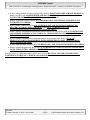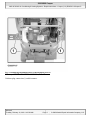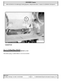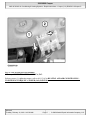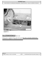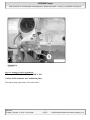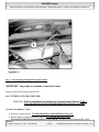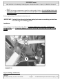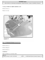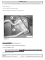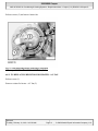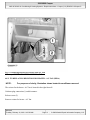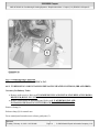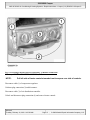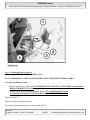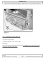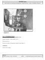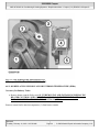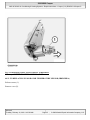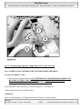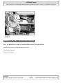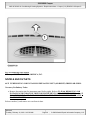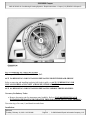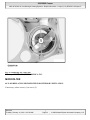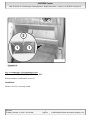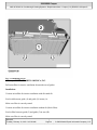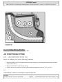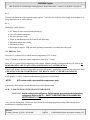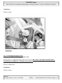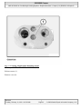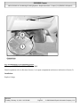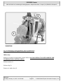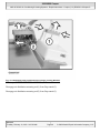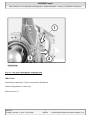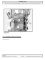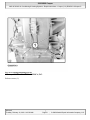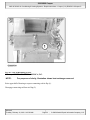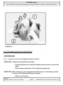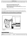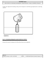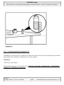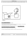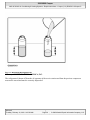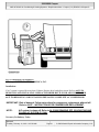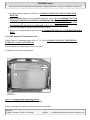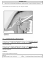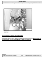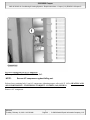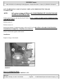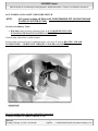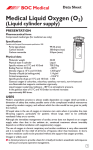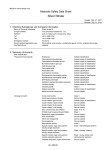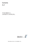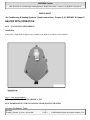
1
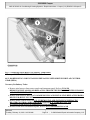
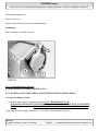
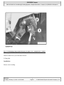
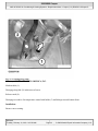
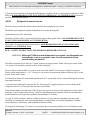
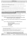
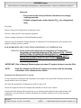
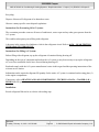
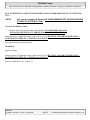
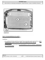
2006 MINI Cooper 2002-05 HVAC Air Conditioning & Heating Systems - Repair Instructions - Cooper (1.6L) R50/W10 & Cooper S 2002-05 HVAC Air Conditioning & Heating Systems - Repair Instructions - Cooper (1.6L) R50/W10 & Cooper S HEATER WITH OPERATION 64 11 ... INSTALLING SERVODRIVE Installation: If necessary, align shaft of flap(s) to be actuated to position of servodrive to be installed. Fig. 1: View Of Servodrive Courtesy of BMW OF NORTH AMERICA, INC. 64 11 200 REMOVING AND INSTALLING OR REPLACING HEATER Necessary Preliminary Tasks: Microsoft Tuesday, February 16, 2010 11:06:03 11:05:58 AM Page 1 © 2005 Mitchell Repair Information Company, LLC. 2006 MINI Cooper 2002-05 HVAC Air Conditioning & Heating Systems - Repair Instructions - Cooper (1.6L) R50/W10 & Cooper S Remove airbag module on front passenger side. Refer to PASSENGER-SIDE AIR BAG MODULE for model year 2002, or PASSENGER-SIDE AIR BAG MODULE for model year 2003, or PASSENGER-SIDE AIR BAG MODULE for model year 2004-05. Remove instrument carrier. Refer to 62 21 000 REMOVING AND INSTALLING/REPLACING INSTRUMENT CARRIER . Remove heater controls. Refer to 64 11 333 REMOVING AND INSTALLING/REPLACING HEATER CONTROLS (IHR AND IHKR) and/or 64 11 334 REMOVING AND INSTALLING/REPLACING HEATER CONTROLS (IHKA). Remove storage compartment in instrument panel trim (driver's side). Refer to 51 16 392 REMOVING AND INSTALLING/REPLACING STORAGE COMPARTMENT IN INSTRUMENT PANEL TRIM (DRIVER'S SIDE) . Remove storage compartment in instrument panel trim (passenger side). Refer to 51 16 390 REMOVING AND INSTALLING/REPLACING INSTRUMENT PANEL TRIM STORAGE TRAY (PASSENGER SIDE) . Remove right glovebox. Refer to 51 16 360 REMOVING AND INSTALLING RIGHT GLOVEBOX . Remove instrument panel trim. Refer to 51 45 030 REMOVING AND INSTALLING INSTRUMENT PANEL TRIM (WITH CARRIER AND HEATER) . Release screws (1), tightening torque, refer to 64 11 2AZ in HEATING AND AIR CONDITIONING TIGHTENING TORQUES - COOPER (1.6L) R50/W10 . Microsoft Tuesday, February 16, 2010 11:05:58 AM Page 2 © 2005 Mitchell Repair Information Company, LLC. 2006 MINI Cooper 2002-05 HVAC Air Conditioning & Heating Systems - Repair Instructions - Cooper (1.6L) R50/W10 & Cooper S Fig. 2: Identifying Instrument Panel Trim Retaining Screws Courtesy of BMW OF NORTH AMERICA, INC. Unfasten plug connection (1) and disconnect. Microsoft Tuesday, February 16, 2010 11:05:58 AM Page 3 © 2005 Mitchell Repair Information Company, LLC. 2006 MINI Cooper 2002-05 HVAC Air Conditioning & Heating Systems - Repair Instructions - Cooper (1.6L) R50/W10 & Cooper S Fig. 3: Locating Plug Connection Courtesy of BMW OF NORTH AMERICA, INC. Disconnect plug (1) from holder (2) on cross-member. Microsoft Tuesday, February 16, 2010 11:05:58 AM Page 4 © 2005 Mitchell Repair Information Company, LLC. 2006 MINI Cooper 2002-05 HVAC Air Conditioning & Heating Systems - Repair Instructions - Cooper (1.6L) R50/W10 & Cooper S Fig. 4: View Of Plug In Cross-Member Courtesy of BMW OF NORTH AMERICA, INC. Release screws (1), tightening torque, refer to 64 11 3AZ in HEATING AND AIR CONDITIONING TIGHTENING TORQUES - COOPER (1.6L) R50/W10 . Microsoft Tuesday, February 16, 2010 11:05:58 AM Page 5 © 2005 Mitchell Repair Information Company, LLC. 2006 MINI Cooper 2002-05 HVAC Air Conditioning & Heating Systems - Repair Instructions - Cooper (1.6L) R50/W10 & Cooper S Fig. 5: Identifying Retaining Screws Courtesy of BMW OF NORTH AMERICA, INC. Release screws (1), tightening torque, refer to 64 11 3AZ in HEATING AND AIR CONDITIONING TIGHTENING TORQUES - COOPER (1.6L) R50/W10 . Microsoft Tuesday, February 16, 2010 11:05:58 AM Page 6 © 2005 Mitchell Repair Information Company, LLC. 2006 MINI Cooper 2002-05 HVAC Air Conditioning & Heating Systems - Repair Instructions - Cooper (1.6L) R50/W10 & Cooper S Fig. 6: Locating Screws For Removal Courtesy of BMW OF NORTH AMERICA, INC. Vehicles With Automatic Air Conditioning Only: Disconnect plug connection (1) for solar sensor. Microsoft Tuesday, February 16, 2010 11:05:58 AM Page 7 © 2005 Mitchell Repair Information Company, LLC. 2006 MINI Cooper 2002-05 HVAC Air Conditioning & Heating Systems - Repair Instructions - Cooper (1.6L) R50/W10 & Cooper S Fig. 7: View Of Plug Connection For Solar Sensor Courtesy of BMW OF NORTH AMERICA, INC. IMPORTANT: Two people are needed to remove the heater. Remove heater from instrument panel trim. 64 11 207 REPLACING HEATER CORE WARNING: Follow instructions for working on cooling system! Refer to 17 00 ... FOLLOW INSTRUCTIONS FOR WORKING ON COOLING SYSTEM . Necessary Preliminary Tasks: Draining coolant. Refer to 17 00 005 DRAINING AND ADDING COOLANT . Remove battery compartment (R50), refer to 61 21 100 REMOVING AND INSTALLING/REPLACING BATTERY CONTAINER , or remove air filter housing (R53 / R50 Microsoft Tuesday, February 16, 2010 11:05:58 AM Page 8 © 2005 Mitchell Repair Information Company, LLC. 2006 MINI Cooper 2002-05 HVAC Air Conditioning & Heating Systems - Repair Instructions - Cooper (1.6L) R50/W10 & Cooper S diesel). Remove left storage compartment or panel for pedal assembly. Refer to 51 16 392 REMOVING AND INSTALLING/REPLACING STORAGE COMPARTMENT IN INSTRUMENT PANEL TRIM (DRIVER'S SIDE) . Release spring clamps (2) and detach coolant hoses (1). IMPORTANT: Carefully blow through aluminum twin pipe to remove remaining coolant from heat exchanger for heating system. Installation: Vent cooling system and check for leaks. Refer to 17 00 009 CHECKING COOLING SYSTEM FOR LEAKS (W10) and/or 17 00 039 BLEEDING COOLING SYSTEM AND CHECKING FOR WATER LEAKS Fig. 8: Locating Coolant Hoses Microsoft Tuesday, February 16, 2010 11:05:59 AM Page 9 © 2005 Mitchell Repair Information Company, LLC. 2006 MINI Cooper 2002-05 HVAC Air Conditioning & Heating Systems - Repair Instructions - Cooper (1.6L) R50/W10 & Cooper S Courtesy of BMW OF NORTH AMERICA, INC. Release screws (1). Remove cover (2). Fig. 9: Identifying Retaining Screws For Cover Courtesy of BMW OF NORTH AMERICA, INC. Release screws (1). Release clamps (2). Remove heater (3). Installation: Make sure heater (3) is correctly seated. Microsoft Tuesday, February 16, 2010 11:05:59 AM Page 10 © 2005 Mitchell Repair Information Company, LLC. 2006 MINI Cooper 2002-05 HVAC Air Conditioning & Heating Systems - Repair Instructions - Cooper (1.6L) R50/W10 & Cooper S Replace sealing rings. Coat new sealing rings with antiseize agent. Make sure sealing rings and clamps (2) are correctly seated. Fig. 10: View Of Heater Courtesy of BMW OF NORTH AMERICA, INC. 64 11 210 REMOVING AND INSTALLING HEATER FAN Necessary Preliminary Tasks: Remove instrument panel trim. Refer to 51 45 030 REMOVING AND INSTALLING INSTRUMENT PANEL TRIM (WITH CARRIER AND HEATER) . Disconnect plug connection (1). Microsoft Tuesday, February 16, 2010 11:05:59 AM Page 11 © 2005 Mitchell Repair Information Company, LLC. 2006 MINI Cooper 2002-05 HVAC Air Conditioning & Heating Systems - Repair Instructions - Cooper (1.6L) R50/W10 & Cooper S Release screws (2) and remove heater fan. Fig. 11: Disconnecting Heater Fan Plug Connection Courtesy of BMW OF NORTH AMERICA, INC. 64 11 221 REPLACING RESISTOR FOR HEATER - A/C FAN Release screw (1). Remove resistor for heater - A/C fan (2). Microsoft Tuesday, February 16, 2010 11:05:59 AM Page 12 © 2005 Mitchell Repair Information Company, LLC. 2006 MINI Cooper 2002-05 HVAC Air Conditioning & Heating Systems - Repair Instructions - Cooper (1.6L) R50/W10 & Cooper S Fig. 12: Removing Resistor For Heater And A/C Fan Courtesy of BMW OF NORTH AMERICA, INC. 64 11 222 REPLACING RESISTOR FOR HEATER - A/C FAN (IHKA) NOTE: For purposes of clarity, illustration shows heater/air conditioner removed. The resistor for the heater - A/C fan is located in the right footwell. Unfasten plug connection (1) and disconnect. Release screw (2). Remove resistor for heater - A/C fan. Microsoft Tuesday, February 16, 2010 11:05:59 AM Page 13 © 2005 Mitchell Repair Information Company, LLC. 2006 MINI Cooper 2002-05 HVAC Air Conditioning & Heating Systems - Repair Instructions - Cooper (1.6L) R50/W10 & Cooper S Fig. 13: Removing Plug Connection Courtesy of BMW OF NORTH AMERICA, INC. 64 11 333 REMOVING AND INSTALLING/REPLACING HEATER CONTROLS (IHR AND IHKR) Necessary Preliminary Tasks: Remove radio receiver. Refer to 65 11 030 REMOVING AND INSTALLING/REPLACING RADIO RECEIVER (BUILT-IN UNIT) . Remove switch block on instrument panel. Refer to 61 31 059 REMOVING AND INSTALLING/REPLACING SWITCH BLOCK IN INSTRUMENT PANEL . Remove clamp (1). Release clamp (2) for control area. Press control panel towards rear to release guide pins (3). Microsoft Tuesday, February 16, 2010 11:05:59 AM Page 14 © 2005 Mitchell Repair Information Company, LLC. 2006 MINI Cooper 2002-05 HVAC Air Conditioning & Heating Systems - Repair Instructions - Cooper (1.6L) R50/W10 & Cooper S Fig. 14: Pressing Control Panel Towards Rear To Release Guide Pins Courtesy of BMW OF NORTH AMERICA, INC. NOTE: Pull left side of heater controls towards front to expose rear side of controls. Disconnect cable (1) of temperature regulator. Unfasten plug connection (2) and disconnect. Disconnect cable (3) of air-distribution controller. Unlock and disconnect plug connection (4) and remove heater controls. Microsoft Tuesday, February 16, 2010 11:05:59 AM Page 15 © 2005 Mitchell Repair Information Company, LLC. 2006 MINI Cooper 2002-05 HVAC Air Conditioning & Heating Systems - Repair Instructions - Cooper (1.6L) R50/W10 & Cooper S Fig. 15: Removing Heater Controls Courtesy of BMW OF NORTH AMERICA, INC. 64 11 334 REMOVING AND INSTALLING/REPLACING HEATER CONTROLS (IHKA) Necessary Preliminary Tasks: Remove radio receiver. Refer to 65 11 030 REMOVING AND INSTALLING/REPLACING RADIO RECEIVER (BUILT-IN UNIT) . Release switch block on instrument panel. Refer to 61 31 059 REMOVING AND INSTALLING/REPLACING SWITCH BLOCK IN INSTRUMENT PANEL . Remove clamp (1). Release clamp (2) for heater controls. Press heater controls towards rear to release guide pins (3). Microsoft Tuesday, February 16, 2010 11:05:59 AM Page 16 © 2005 Mitchell Repair Information Company, LLC. 2006 MINI Cooper 2002-05 HVAC Air Conditioning & Heating Systems - Repair Instructions - Cooper (1.6L) R50/W10 & Cooper S Fig. 16: Releasing Heater Controls Guide Pins Courtesy of BMW OF NORTH AMERICA, INC. Pull out heater controls slightly. Unlock plug connections (1) and (2) and disconnect. Replacement: Remove sensor blower for interior temperature. Refer to 64 11 889 REPLACING SENSOR FAN FOR INTERIOR TEMPERATURE (IHKA). Microsoft Tuesday, February 16, 2010 11:05:59 AM Page 17 © 2005 Mitchell Repair Information Company, LLC. 2006 MINI Cooper 2002-05 HVAC Air Conditioning & Heating Systems - Repair Instructions - Cooper (1.6L) R50/W10 & Cooper S Fig. 17: Removing Sensor Blower For Interior Temperature Courtesy of BMW OF NORTH AMERICA, INC. 64 11 800 REMOVING AND INSTALLING/REPLACING SERVODRIVE FOR FLAP CONTROL GEAR (IHKA) Necessary Preliminary Tasks: Remove trim between front center console and instrument panel. Refer to 51 16 198 REMOVING/INSTALLING OR REPLACING TRIM BETWEEN FRONT CENTER CONSOLE AND INSTRUMENT PANEL . Remove radio receiver. Refer to 65 11 030 REMOVING AND INSTALLING/REPLACING RADIO RECEIVER (BUILT-IN UNIT) . Remove heater controls. Refer to 64 11 333 REMOVING AND INSTALLING/REPLACING HEATER CONTROLS (IHR AND IHKR) AND/OR 64 11 334 REMOVING AND INSTALLING/REPLACING HEATER CONTROLS (IHKA). Release switch block on instrument panel. Refer to 61 31 059 REMOVING AND Microsoft Tuesday, February 16, 2010 11:05:59 AM Page 18 © 2005 Mitchell Repair Information Company, LLC. 2006 MINI Cooper 2002-05 HVAC Air Conditioning & Heating Systems - Repair Instructions - Cooper (1.6L) R50/W10 & Cooper S INSTALLING/REPLACING SWITCH BLOCK IN INSTRUMENT PANEL . Unfasten plug connection (1) and disconnect. Release screws (2) and remove servodrive for flap control gear. Fig. 18: View Of Servodrive For Flap Control Gear Courtesy of BMW OF NORTH AMERICA, INC. 64 11 805 REMOVING AND INSTALLING/REPLACING SERVODRIVE FOR FRESHAIR/REIRCULATED-AIR FLAP Necessary Preliminary Tasks: Remove right storage compartment, refer to 51 16 390 REMOVING AND INSTALLING/REPLACING INSTRUMENT PANEL TRIM STORAGE TRAY (PASSENGER SIDE) , or remove glovebox, refer to 51 16 360 REMOVING AND INSTALLING RIGHT GLOVEBOX . Microsoft Tuesday, February 16, 2010 11:05:59 AM Page 19 © 2005 Mitchell Repair Information Company, LLC. 2006 MINI Cooper 2002-05 HVAC Air Conditioning & Heating Systems - Repair Instructions - Cooper (1.6L) R50/W10 & Cooper S Detach plug connector (1). Remove screws (2). Pull servodrive forwards away from flap mechanism. Installation: The servodrive is seated in a keyway. Fig. 19: Detaching Plug Connector Courtesy of BMW OF NORTH AMERICA, INC. 64 11 861 REPLACING SERVODRIVE FOR TEMPERATURE CONTROL (IHKA) Necessary Preliminary Tasks: Remove right storage compartment, refer to 51 16 390 REMOVING AND INSTALLING/REPLACING INSTRUMENT PANEL TRIM STORAGE TRAY (PASSENGER SIDE) , or glovebox, refer to 51 16 360 REMOVING AND INSTALLING RIGHT GLOVEBOX . Unlock and disconnect plug connection (1) of servodrive for temperature control (2). Microsoft Tuesday, February 16, 2010 11:05:59 AM Page 20 © 2005 Mitchell Repair Information Company, LLC. 2006 MINI Cooper 2002-05 HVAC Air Conditioning & Heating Systems - Repair Instructions - Cooper (1.6L) R50/W10 & Cooper S Fig. 20: Identifying Plug Connection Of Servodrive For Temperature Control Courtesy of BMW OF NORTH AMERICA, INC. Detach control lever (1) in direction of arrow. 2) Drag link. Installation: Ensure correct seating. Microsoft Tuesday, February 16, 2010 11:05:59 AM Page 21 © 2005 Mitchell Repair Information Company, LLC. 2006 MINI Cooper 2002-05 HVAC Air Conditioning & Heating Systems - Repair Instructions - Cooper (1.6L) R50/W10 & Cooper S Fig. 21: Locating Drag Link Courtesy of BMW OF NORTH AMERICA, INC. Slacken cable (1). Disengage drag link (2) in direction of arrow. Release catch (4). Disengage servodrive for temperature control with holder (3) and linkage towards bottom front. Installation: Ensure correct seating. Microsoft Tuesday, February 16, 2010 11:05:59 AM Page 22 © 2005 Mitchell Repair Information Company, LLC. 2006 MINI Cooper 2002-05 HVAC Air Conditioning & Heating Systems - Repair Instructions - Cooper (1.6L) R50/W10 & Cooper S Fig. 22: Disengaging Servodrive Courtesy of BMW OF NORTH AMERICA, INC. Separate drag link (1) from control lever (2). Release screws (4). Remove servodrive for temperature control (5) from holder (3). Installation: Ensure correct seating. Microsoft Tuesday, February 16, 2010 11:05:59 AM Page 23 © 2005 Mitchell Repair Information Company, LLC. 2006 MINI Cooper 2002-05 HVAC Air Conditioning & Heating Systems - Repair Instructions - Cooper (1.6L) R50/W10 & Cooper S Fig. 23: View Of Drag Link And Control Lever Courtesy of BMW OF NORTH AMERICA, INC. 64 11 889 REPLACING SENSOR FAN FOR INTERIOR TEMPERATURE (IHKA) Necessary Preliminary Tasks: Remove heater controls. Refer to 64 11 333 REMOVING AND INSTALLING/REPLACING HEATER CONTROLS (IHR AND IHKR) AND/OR 64 11 334 REMOVING AND INSTALLING/REPLACING HEATER CONTROLS (IHKA). Remove sensor fan for interior temperature (1) from heater controls. Microsoft Tuesday, February 16, 2010 11:05:59 AM Page 24 © 2005 Mitchell Repair Information Company, LLC. 2006 MINI Cooper 2002-05 HVAC Air Conditioning & Heating Systems - Repair Instructions - Cooper (1.6L) R50/W10 & Cooper S Fig. 24: Identifying Sensor Fan For Interior Temperature Courtesy of BMW OF NORTH AMERICA, INC. 64 11 932 REPLACING EVAPORATOR TEMPERATURE SENSOR (IHKR/IHKA) Release screws (1). Remove cover (2). Microsoft Tuesday, February 16, 2010 11:05:59 AM Page 25 © 2005 Mitchell Repair Information Company, LLC. 2006 MINI Cooper 2002-05 HVAC Air Conditioning & Heating Systems - Repair Instructions - Cooper (1.6L) R50/W10 & Cooper S Fig. 25: Locating Retaining Screws For Cover Courtesy of BMW OF NORTH AMERICA, INC. Turn evaporator temperature sensor (1) counterclockwise (approx. 45°) and pull out. Unfasten plug connection (2) and disconnect. Installation: Make sure that opening (3) of evaporator temperature sensor (1) is correctly aligned. Microsoft Tuesday, February 16, 2010 11:05:59 AM Page 26 © 2005 Mitchell Repair Information Company, LLC. 2006 MINI Cooper 2002-05 HVAC Air Conditioning & Heating Systems - Repair Instructions - Cooper (1.6L) R50/W10 & Cooper S Fig. 26: Disconnecting Evaporator Temperature Sensor Plug Connection Courtesy of BMW OF NORTH AMERICA, INC. 64 11 939 REPLACING TEMPERATURE SENSOR FOR HEATER (IHKA) Necessary Preliminary Tasks: Remove heater controls. Refer to 64 11 333 REMOVING AND INSTALLING/REPLACING HEATER CONTROLS (IHR AND IHKR) AND/OR 64 11 334 REMOVING AND INSTALLING/REPLACING HEATER CONTROLS (IHKA). Turn temperature sensor for heater (1) clockwise (approx. 45°) and pull out. Unfasten plug connection (2) and disconnect. Installation: Make sure that opening (3) of temperature sensor for heater is correctly aligned. Microsoft Tuesday, February 16, 2010 11:05:59 AM Page 27 © 2005 Mitchell Repair Information Company, LLC. 2006 MINI Cooper 2002-05 HVAC Air Conditioning & Heating Systems - Repair Instructions - Cooper (1.6L) R50/W10 & Cooper S Fig. 27: Disconnecting Temperature Sensor Plug Connection Courtesy of BMW OF NORTH AMERICA, INC. 64 11 992 REMOVING AND INSTALLING/REPLACING SOLAR SENSOR Remove solar sensor (1) from instrument panel trim. Detach plug connector. Remove solar sensor. Microsoft Tuesday, February 16, 2010 11:05:59 AM Page 28 © 2005 Mitchell Repair Information Company, LLC. 2006 MINI Cooper 2002-05 HVAC Air Conditioning & Heating Systems - Repair Instructions - Cooper (1.6L) R50/W10 & Cooper S Fig. 28: Removing Solar Sensor Courtesy of BMW OF NORTH AMERICA, INC. NOZZLE AND OUTLETS 64 22 135 REMOVING AND INSTALLING/REPLACING LEFT (OR RIGHT) FRESH AIR GRILL Necessary Preliminary Tasks: Remove decorative trim for instrument panel (left or right). Refer to 51 45 066 REMOVING AND INSTALLING DECORATIVE TRIM FOR INSTRUMENT PANEL (DRIVER'S SIDE) and/or 51 45 068 REMOVING AND INSTALLING DECORATIVE TRIM FOR INSTRUMENT PANEL (PASSENGER SIDE) . Release catches (1) and remove air vent from air duct. Microsoft Tuesday, February 16, 2010 11:05:59 AM Page 29 © 2005 Mitchell Repair Information Company, LLC. 2006 MINI Cooper 2002-05 HVAC Air Conditioning & Heating Systems - Repair Instructions - Cooper (1.6L) R50/W10 & Cooper S Fig. 29: Removing Air Vent From Air Duct Courtesy of BMW OF NORTH AMERICA, INC. 64 22 136 REMOVING AND INSTALLING/REPLACING RIGHT FRESH-AIR GRILLE Refer to removing and installing/replacing left fresh-air grille, see 64 22 135 REMOVING AND INSTALLING/REPLACING LEFT (OR RIGHT) FRESH AIR GRILL. 64 22 161 REMOVING AND INSTALLING/REPLACING MIDDLE FRESH AIR GRILL Necessary Preliminary Tasks: Remove decorative trim for instrument panel (middle). Refer to 51 45 060 REMOVING AND INSTALLING/REPLACING DECORATIVE TRIM FOR INSTRUMENT PANEL (MIDDLE) . Turn trim ring of air vent (1) and detach towards front. Installation: Microsoft Tuesday, February 16, 2010 11:05:59 AM Page 30 © 2005 Mitchell Repair Information Company, LLC. 2006 MINI Cooper 2002-05 HVAC Air Conditioning & Heating Systems - Repair Instructions - Cooper (1.6L) R50/W10 & Cooper S Rims must snap into place correctly. Fig. 30: Identifying Trim Ring Of Air Vent Courtesy of BMW OF NORTH AMERICA, INC. Release clips (1) and remove air vent. Microsoft Tuesday, February 16, 2010 11:05:59 AM Page 31 © 2005 Mitchell Repair Information Company, LLC. 2006 MINI Cooper 2002-05 HVAC Air Conditioning & Heating Systems - Repair Instructions - Cooper (1.6L) R50/W10 & Cooper S Fig. 31: Removing Air Vent Clips Courtesy of BMW OF NORTH AMERICA, INC. MICROFILTER 64 31 009 REPLACING MICROFILTER FOR INTERIOR VENTILATION If necessary, release screws (1) on cover (2). Microsoft Tuesday, February 16, 2010 11:05:59 AM Page 32 © 2005 Mitchell Repair Information Company, LLC. 2006 MINI Cooper 2002-05 HVAC Air Conditioning & Heating Systems - Repair Instructions - Cooper (1.6L) R50/W10 & Cooper S Fig. 32: Removing Cover Retaining Screws Courtesy of BMW OF NORTH AMERICA, INC. Release catches (1) and remove cover (2). Installation: Ensure cover (2) is correctly seated. Microsoft Tuesday, February 16, 2010 11:05:59 AM Page 33 © 2005 Mitchell Repair Information Company, LLC. 2006 MINI Cooper 2002-05 HVAC Air Conditioning & Heating Systems - Repair Instructions - Cooper (1.6L) R50/W10 & Cooper S Fig. 33: Installing Cover Courtesy of BMW OF NORTH AMERICA, INC. Pull microfilter for interior ventilation downwards out of guides. Installation: Version: microfilter for interior ventilation with all-round rib: Feed in rib between guide (1) and guide (2) in area (A). Make sure filter is correctly seated. Version: microfilter for interior ventilation without rib (block filter): Feed in filter between guide (2) and guide (3) in area (B). Make sure filter is correctly seated. Microsoft Tuesday, February 16, 2010 11:05:59 AM Page 34 © 2005 Mitchell Repair Information Company, LLC. 2006 MINI Cooper 2002-05 HVAC Air Conditioning & Heating Systems - Repair Instructions - Cooper (1.6L) R50/W10 & Cooper S Fig. 34: Locating Guides For Microfilter Courtesy of BMW OF NORTH AMERICA, INC. AIR CONDITIONING SYSTEM 64 50 ... AIR CONDITIONER TEST (R 134A) Before A/C Efficiency Test, Satisfy Following Conditions : 1. Provide a MoDiC or DIS. Safeguard electrical system integrity by checking the fault memory (no faults in the fault memory). 2. Provide a thermometer with separate gauge. 3. Perform the test in a suitable work bay with an ambient temperature between 20° C and 30° C. Re 1: Connect MoDiC or DIS to car and display evaporator temperature. Microsoft Tuesday, February 16, 2010 11:05:59 AM Page 35 © 2005 Mitchell Repair Information Company, LLC. 2006 MINI Cooper 2002-05 HVAC Air Conditioning & Heating Systems - Repair Instructions - Cooper (1.6L) R50/W10 & Cooper S Re 2: Position a thermometer with a separate gauge approx. 5 cm below the roofliner at the height of the B-pillar. Lay gauge outwards out of vehicle interior. Re 3: Heating up vehicle interior: A/C button is not activated during heating up. Close all windows and doors. Set recirculated air mode. Select air distribution mode for footwell and defrosting. Maximum temperature setting. Maximum fan stage. Run engine at approx. 2000 rpm until operating temperature is reached, then idle speed. A/C Efficiency Test: Turn on A/C compressor at a vehicle interior temperature of 50° Celsius. After 2-3 minutes, evaporator sensor temperature must be 10° Celsius. Draw off A/C system if this temperature is not reached. Measure amount of refrigerant drawn off. Refer to 64 50 009 DRAWING OFF, EVACUATING AND FILLING A/C SYSTEM (R 134A). If drawn-off quantity does not correspond to specified fill quantity: supplement refrigerant and repeat test. Refer to HEATING AND AIR CONDITIONING - TECHNICAL DATA - COOPER (1.6L) R50/W10 . If fill quantity is correct, continue troubleshooting by pressure measurement. NOTE: A/C systems with uncontrolled compressors only: If necessary, then continue troubleshooting by pressure measurement. 64 50 ... LEAK-TESTING WITH LEAK TESTER DEVICE WARNING: Avoid contact with refrigerant. Follow safety precautions when handling refrigerant. Refer to 64 50 ... SAFETY INSTRUCTIONS FOR HANDLING REFRIGERANT R 134A Carry out leak-testing with a leak tester device from the workshop equipment catalog following the device manufacturer's operating instructions. Microsoft Tuesday, February 16, 2010 11:05:59 AM Page 36 © 2005 Mitchell Repair Information Company, LLC. 2006 MINI Cooper 2002-05 HVAC Air Conditioning & Heating Systems - Repair Instructions - Cooper (1.6L) R50/W10 & Cooper S If leaks not to be localized are already identified during evacuation, the A/C system must nevertheless be filled. Refer to 64 50 009 DRAWING OFF, EVACUATING AND FILLING A/C SYSTEM (R 134A). Then test for leaks with leak tester device. NOTE: Refrigerant is heavier than air. Therefore always conduct the leak test below the lines and components to be tested. Shield lines and components against strong blasts of air (wind, drawing off). Tighten down loose lines, mark leaks. Then draw off draw off A/C system and seal off or repair leakage points. Refer to 64 50 009 DRAWING OFF, EVACUATING AND FILLING A/C SYSTEM (R 134A). Then refill A/C system and test for leaks. Refer to 64 50 009 DRAWING OFF, EVACUATING AND FILLING A/C SYSTEM (R 134A). 64 50 ... SAFETY INSTRUCTIONS FOR HANDLING REFRIGERANT R 134A WARNING: Although R 134a at normal temperature is non-toxic, non-flammable and not explosive in air in any mixture ratio, it is still essential to follow various safety precautions. The filled refrigerant circuit of the A/C system is subject to gauge pressure. When carrying out repairs on the A/C system, it is absolutely essential to draw off the refrigerant. Do not weld or solder on filled A/C systems or in rooms into which R 134a may have leaked. Exposure to flames or high temperatures (>/= 50° C) may give rise to toxic decomposition products (fluorine gas). For this reason, do not smoke either. R 134a must be drawn off, cleaned and returned to the A/C system with a service station following the relevant operating instructions. Avoid all contact with liquid or gaseous R 134a. Wear protective goggles and gloves when working on the refrigerant circuit. R 134a acting on the skin can cause frostbite. Wash off thoroughly with cold water. If R 134a gets into your eyes, likewise rinse with plenty of water and, if necessary, remove contact lenses if worn. Then seek immediate medical attention. Likewise seek immediate medical attention if you experience problems after inhaling R 134a fumes. As a gas, R 134a is colorless, odorless and heavier than air. If it gets into the atmosphere, this may result especially in workshop pits in an imperceptible danger of asphyxiation or in cardiac palpitations. Ventilate rooms adequately; if necessary, turn on installed extractor systems. For a properly functioning A/C system, it is essential to have the greatest possible levels of cleanliness when Microsoft Tuesday, February 16, 2010 11:05:59 AM Page 37 © 2005 Mitchell Repair Information Company, LLC. 2006 MINI Cooper 2002-05 HVAC Air Conditioning & Heating Systems - Repair Instructions - Cooper (1.6L) R50/W10 & Cooper S working on the A/C system and the best possible evacuation (at least 30 minutes dehumidification from refrigerant circuit) before each filling of the A/C system. R 134a absorbs moisture very easily. Therefore seal off opened pipes, condenser, evaporator, compressor and drier bottle immediately with plugs. With replacement parts, the plugs may only be removed immediately before the lines are connected. In the event of warranty claims, the old parts must be provided with plugs to be able to determine the cause of the damage. If an A/C system has been completely drained by leakage, accident or repair, the drier element must be replace as excessive moisture may have entered the system. Refer to 64 53 510 REMOVING AND INSTALLING / REPLACING DRIER BOTTLE FOR AIR CONDITIONER. Store filled pressurized refrigerant bottles in such a way that they are not exposed to direct sunlight or other heat sources (max. 45° C). Also avoid exposing them to mechanical stress (e.g. by dropping). In the event of fire, carbon dioxide (CO2), extinguishant powder and a sprayed water jet are deemed to be suitable extinguishants. Cool reservoirs at risk with a sprayed water jet (risk of bursting!). CAUTION: After each refill of an A/C system, check that protective caps of filling valves are hand-tight. They serve as additional seals. 64 50 ... SAFETY PRECAUTIONS WHEN HANDLING REFRIGERANT OIL (FOR REFRIGERANT R 134A) WARNING: Observe the following points when handling refrigerant oil: Wear protective goggles. Wear gloves made from impermeable plastic. Do not swallow. Do not inhale. Action to be taken after contact with refrigerant oil: After contact with eyes, rinse thoroughly with plenty of water and take out contact lenses (if worn). Then seek immediate medical attention. After contact with the skin, wash body parts affected with plenty of soap and water. Do not induce vomiting if oil is swallowed, seek immediate medical attention. If inhaled, introduce the person affected to fresh air. Seek medical attention if problems persist. WARNING: Refrigerant oil is non-combustible and non-explosive at normal temperatures. In spite of this, the following precautions must be Microsoft Tuesday, February 16, 2010 11:05:59 AM Page 38 © 2005 Mitchell Repair Information Company, LLC. 2006 MINI Cooper 2002-05 HVAC Air Conditioning & Heating Systems - Repair Instructions - Cooper (1.6L) R50/W10 & Cooper S observed: Do not store in the vicinity of flames, heat sources or strongly oxidizing materials. Suitable extinguishants: carbon dioxide (CO2 ), dry extinguishant, foam. Recycling: Dispose of drawn-off refrigerant oil as hazardous waste. Observe country-specific waste-disposal regulations. Absorb escaping refrigerant oil with fluid-binding material. Notify the relevant authorities if larger amounts of refrigerant oil are discharged into above-ground water supplies, drainage systems or subsoil. 64 50 009 DRAWING OFF, EVACUATING AND FILLING A/C SYSTEM (R 134A) WARNING: Avoid contact with refrigerant and refrigerant oil. Follow safety instructions for handling refrigerant R 134a. Refer to 64 50 ... SAFETY INSTRUCTIONS FOR HANDLING REFRIGERANT R 134A. Follow safety instructions for handling refrigerant oil. Refer to 64 50 ... SAFETY PRECAUTIONS WHEN HANDLING REFRIGERANT OIL (FOR REFRIGERANT R 134A). IMPORTANT: Risk of damage! Restart engine only when A/C system has been correctly filled. NOTE: Draw off, evacuate and fill the A/C system in accordance with the operating instructions of the relevant service station. Instructions For Drawing Off A/C System: To help separation of refrigerant and refrigerant oil, run engine at low speed (800-1200 rpm) and with A/C system turned on for a few minutes. The limits the entrainment of refrigerant oil while it is drawn off. Drawn-off refrigerant oil must be changed and reintroduced via the service station. If at the end of the drawing-off procedure the service station moisture indicator shows that the drawn-off refrigerant is excessively moist, clean the refrigerant in accordance with the service station operating instructions. Microsoft Tuesday, February 16, 2010 11:05:59 AM Page 39 © 2005 Mitchell Repair Information Company, LLC. 2006 MINI Cooper 2002-05 HVAC Air Conditioning & Heating Systems - Repair Instructions - Cooper (1.6L) R50/W10 & Cooper S Recycling: Dispose of drawn-off refrigerant oil as hazardous waste. Observe country-specific waste-disposal regulations. Instructions For Evacuating Off A/C System: The evacuation procedure removes all traces of ambient air, water vapor and any other gases present from the A/C system. This enables subsequent system filling with refrigerant. A decrease in the vacuum level indicates a leak in the refrigerant circuit. Refer to 64 50 ... LEAK-TESTING WITH LEAK TESTER DEVICE. Instructions For Filling A/C System: Before filling with refrigerant, top up the refrigerant oil entrained during drawing off. Depending on the type of component replaced on the A/C system, it may be necessary to top up the refrigerant oil, even if no measurable losses have occurred during drawing off. Read and comply with the A/C system manufacturer's notes in this regard and the operating instructions of the relevant service station. Information on the required refrigerant fill quantity for the entire A/C system is contained on the rating plate (1) in the engine compartment. If necessary, refer to HEATING AND AIR CONDITIONING - TECHNICAL DATA - COOPER (1.6L) R50/W10 for fill quantities. Installation: Reseal refrigerant filler necks on vehicle with sealing caps. Microsoft Tuesday, February 16, 2010 11:05:59 AM Page 40 © 2005 Mitchell Repair Information Company, LLC. 2006 MINI Cooper 2002-05 HVAC Air Conditioning & Heating Systems - Repair Instructions - Cooper (1.6L) R50/W10 & Cooper S Fig. 35: Identifying Rating Plate Courtesy of BMW OF NORTH AMERICA, INC. A/C HOUSING/EVAP., SWITCHING ELEMENTS 64 51 522 REMOVING AND INSTALLING OR REPLACING EXPANSION VALVE Necessary Preliminary Tasks: Draw off refrigerant from A/C system W10 only: Remove battery container. Refer to 64 50 009 DRAWING OFF, EVACUATING AND FILLING A/C SYSTEM (R 134A). Release screws (1), tightening torque, refer to 64 11 4AZ in HEATING AND AIR CONDITIONING TIGHTENING TORQUES - COOPER (1.6L) R50/W10 . Detach refrigerant lines. Microsoft Tuesday, February 16, 2010 11:05:59 AM Page 41 © 2005 Mitchell Repair Information Company, LLC. 2006 MINI Cooper 2002-05 HVAC Air Conditioning & Heating Systems - Repair Instructions - Cooper (1.6L) R50/W10 & Cooper S Installation: Replace O-rings. Fig. 36: Detaching Refrigerant Lines Courtesy of BMW OF NORTH AMERICA, INC. Release screws (1), tightening torque, refer to 64 11 5AZ in HEATING AND AIR CONDITIONING TIGHTENING TORQUES - COOPER (1.6L) R50/W10 . Remove adapter block. Installation: Replace O-rings. Microsoft Tuesday, February 16, 2010 11:05:59 AM Page 42 © 2005 Mitchell Repair Information Company, LLC. 2006 MINI Cooper 2002-05 HVAC Air Conditioning & Heating Systems - Repair Instructions - Cooper (1.6L) R50/W10 & Cooper S Fig. 37: Locating Adapter Block Retaining Screws Courtesy of BMW OF NORTH AMERICA, INC. Release screws (1). Remove cover (2). Microsoft Tuesday, February 16, 2010 11:05:59 AM Page 43 © 2005 Mitchell Repair Information Company, LLC. 2006 MINI Cooper 2002-05 HVAC Air Conditioning & Heating Systems - Repair Instructions - Cooper (1.6L) R50/W10 & Cooper S Fig. 38: Identifying Cover Retaining Screws Courtesy of BMW OF NORTH AMERICA, INC. Detach expansion valve in direction of arrow (1) to engine compartment and remove in direction of arrow (2). Installation: Replace O-rings. Microsoft Tuesday, February 16, 2010 11:05:59 AM Page 44 © 2005 Mitchell Repair Information Company, LLC. 2006 MINI Cooper 2002-05 HVAC Air Conditioning & Heating Systems - Repair Instructions - Cooper (1.6L) R50/W10 & Cooper S Fig. 39: Detaching Expansion Valve Courtesy of BMW OF NORTH AMERICA, INC. 64 51 590 REMOVING AND INSTALLING/REPLACING EVAPORATOR NOTE: The heater is removed. Refer to 64 11 200 REMOVING AND INSTALLING OR REPLACING HEATER. Necessary Preliminary Tasks: Remove evaporator temperature sensor. Refer to 64 11 932 REPLACING EVAPORATOR TEMPERATURE SENSOR (IHKR/IHKA). Unfasten plug connection (1) and disconnect. Remove wiring harness (2) from air intake duct. Microsoft Tuesday, February 16, 2010 11:05:59 AM Page 45 © 2005 Mitchell Repair Information Company, LLC. 2006 MINI Cooper 2002-05 HVAC Air Conditioning & Heating Systems - Repair Instructions - Cooper (1.6L) R50/W10 & Cooper S Fig. 40: Identifying Wiring Harness From Air Intake Duct Courtesy of BMW OF NORTH AMERICA, INC. IHKA Only: Remove servodrive for temperature control. Refer in 64 11 861 REPLACING SERVODRIVE FOR TEMPERATURE CONTROL (IHKA). Release screws (1). Release clip (2). Remove air intake duct (3). Microsoft Tuesday, February 16, 2010 11:05:59 AM Page 46 © 2005 Mitchell Repair Information Company, LLC. 2006 MINI Cooper 2002-05 HVAC Air Conditioning & Heating Systems - Repair Instructions - Cooper (1.6L) R50/W10 & Cooper S Fig. 41: Locating Air Intake Duct Courtesy of BMW OF NORTH AMERICA, INC. Unfasten plug connection (1) and disconnect. Disconnect plug (2) for heater wiring harness from housing. Microsoft Tuesday, February 16, 2010 11:05:59 AM Page 47 © 2005 Mitchell Repair Information Company, LLC. 2006 MINI Cooper 2002-05 HVAC Air Conditioning & Heating Systems - Repair Instructions - Cooper (1.6L) R50/W10 & Cooper S Fig. 42: Identifying Plug Connection For Heater Wiring Harness Courtesy of BMW OF NORTH AMERICA, INC. Disengage air distribution actuating rod (1) from flap control (3). Disengage air distribution actuating rod (2) from flap control (3). Microsoft Tuesday, February 16, 2010 11:05:59 AM Page 48 © 2005 Mitchell Repair Information Company, LLC. 2006 MINI Cooper 2002-05 HVAC Air Conditioning & Heating Systems - Repair Instructions - Cooper (1.6L) R50/W10 & Cooper S Fig. 43: View Of Air Distribution Actuating Rod Courtesy of BMW OF NORTH AMERICA, INC. IHKA Only: Detach plug connection (1) from servomotor/air distribution. Detach wiring harness (2) from clip. Release screws (3). Microsoft Tuesday, February 16, 2010 11:05:59 AM Page 49 © 2005 Mitchell Repair Information Company, LLC. 2006 MINI Cooper 2002-05 HVAC Air Conditioning & Heating Systems - Repair Instructions - Cooper (1.6L) R50/W10 & Cooper S Fig. 44: Identifying Servomotor/Air Distribution Courtesy of BMW OF NORTH AMERICA, INC. Release screws (1). Microsoft Tuesday, February 16, 2010 11:05:59 AM Page 50 © 2005 Mitchell Repair Information Company, LLC. 2006 MINI Cooper 2002-05 HVAC Air Conditioning & Heating Systems - Repair Instructions - Cooper (1.6L) R50/W10 & Cooper S Fig. 45: Locating Retaining Screws Courtesy of BMW OF NORTH AMERICA, INC. Release screws (1). Microsoft Tuesday, February 16, 2010 11:05:59 AM Page 51 © 2005 Mitchell Repair Information Company, LLC. 2006 MINI Cooper 2002-05 HVAC Air Conditioning & Heating Systems - Repair Instructions - Cooper (1.6L) R50/W10 & Cooper S Fig. 46: View Of Retaining Screws Courtesy of BMW OF NORTH AMERICA, INC. NOTE: For purposes of clarity, illustration shows heat exchanger removed. Raise upper half of housing to expose connecting rod/air flap (1). Disengage connecting rod from air flap (2). Microsoft Tuesday, February 16, 2010 11:05:59 AM Page 52 © 2005 Mitchell Repair Information Company, LLC. 2006 MINI Cooper 2002-05 HVAC Air Conditioning & Heating Systems - Repair Instructions - Cooper (1.6L) R50/W10 & Cooper S Fig. 47: Locating Connecting Rod/Air Flap Courtesy of BMW OF NORTH AMERICA, INC. Remove evaporator (1) from lower half of housing (2). Replacement: Remove expansion valve from evaporator (1). Refer to 64 51 522 REMOVING AND INSTALLING OR REPLACING EXPANSION VALVE. Microsoft Tuesday, February 16, 2010 11:05:59 AM Page 53 © 2005 Mitchell Repair Information Company, LLC. 2006 MINI Cooper 2002-05 HVAC Air Conditioning & Heating Systems - Repair Instructions - Cooper (1.6L) R50/W10 & Cooper S Fig. 48: Removing Expansion Valve From Evaporator Courtesy of BMW OF NORTH AMERICA, INC. COMPRESSOR 64 52 ... INSTRUCTIONS FOR COMPRESSOR REPLACEMENT IMPORTANT: Compressors with plastic belt pulleys: Avoid impacts/knocks to plastic belt pulley (caused by tools, contact with base). Return faulty compressors in their original packaging only. IMPORTANT: When starting up a new compressor for the first time, it is absolutely essential to carry out the following breaking-in procedure: Switch on A/C system. Microsoft Tuesday, February 16, 2010 11:05:59 AM Page 54 © 2005 Mitchell Repair Information Company, LLC. 2006 MINI Cooper 2002-05 HVAC Air Conditioning & Heating Systems - Repair Instructions - Cooper (1.6L) R50/W10 & Cooper S Set all air vents in instrument cluster to "OPEN". Start engine and let it stabilize at idle speed. Set blower output to min. 75% of max. blower output. Switch on A/C system and run for at least 2 minutes at idle speed (risk of damage at higher speed!). When evacuating the air-conditioning system, refrigerant oil is also extracted and collected in the oil separator of the service station. After evacuation, the refrigerant must be filtered in the service station as the oil separator could still contain a liquid refrigerant/oil mixture. The filtering process gasifies the refrigerant completely and only the previously bound refrigerant oil remains in the oil separator. Measure and note down this quantity of refrigerant oil, refer to 64 50 009 DRAWING OFF, EVACUATING AND FILLING A/C SYSTEM (R 134A). Fig. 49: View Of Oil Separator Courtesy of BMW OF NORTH AMERICA, INC. Microsoft Tuesday, February 16, 2010 11:05:59 AM Page 55 © 2005 Mitchell Repair Information Company, LLC. 2006 MINI Cooper 2002-05 HVAC Air Conditioning & Heating Systems - Repair Instructions - Cooper (1.6L) R50/W10 & Cooper S Transfer the refrigerant oil remaining in the previous compressor via the filler plug completely into a measuring container. Fig. 50: Transferring Refrigerant Oil Into Measuring Container Courtesy of BMW OF NORTH AMERICA, INC. Measure the amount of refrigerant oil collected from the previous compressor. Microsoft Tuesday, February 16, 2010 11:05:59 AM Page 56 © 2005 Mitchell Repair Information Company, LLC. 2006 MINI Cooper 2002-05 HVAC Air Conditioning & Heating Systems - Repair Instructions - Cooper (1.6L) R50/W10 & Cooper S Fig. 51: Measuring Amount Of Refrigerant Oil Courtesy of BMW OF NORTH AMERICA, INC. Depending on its design, the new compressor is filled at the factory with 120 to 200 g refrigerant oil. Open filler plug and pour entire contents of compressor into a clean container. Installation: If necessary, replace gasket. Observe tightening torque, refer to 64 52 2AZ in HEATING AND AIR CONDITIONING - TIGHTENING TORQUES - COOPER (1.6L) R50/W10 . Microsoft Tuesday, February 16, 2010 11:05:59 AM Page 57 © 2005 Mitchell Repair Information Company, LLC. 2006 MINI Cooper 2002-05 HVAC Air Conditioning & Heating Systems - Repair Instructions - Cooper (1.6L) R50/W10 & Cooper S Fig. 52: Identifying Refrigerant Oil Courtesy of BMW OF NORTH AMERICA, INC. From this refrigerant oil, pour the same amount (as drained from the previous compressor) + 10 g extra into a clean measuring container and pour again into the new compressor. Remaining refrigerant oil can be poured into service station tank, refer to 64 50 009 DRAWING OFF, EVACUATING AND FILLING A/C SYSTEM (R 134A). Otherwise the excess refrigerant oil must be disposed of correctly. On account of its hygroscopic properties, refrigerant oil must not be stored in open containers. Microsoft Tuesday, February 16, 2010 11:05:59 AM Page 58 © 2005 Mitchell Repair Information Company, LLC. 2006 MINI Cooper 2002-05 HVAC Air Conditioning & Heating Systems - Repair Instructions - Cooper (1.6L) R50/W10 & Cooper S Fig. 53: Measuring Refrigerant Oil Courtesy of BMW OF NORTH AMERICA, INC. The refrigerant oil drawn off from the oil separator of the service station and from the previous compressor must not be reused and must be correctly disposed of. Microsoft Tuesday, February 16, 2010 11:05:59 AM Page 59 © 2005 Mitchell Repair Information Company, LLC. 2006 MINI Cooper 2002-05 HVAC Air Conditioning & Heating Systems - Repair Instructions - Cooper (1.6L) R50/W10 & Cooper S Fig. 54: Identifying Correct Disposal Of Refrigerant Oil Courtesy of BMW OF NORTH AMERICA, INC. After installing the new compressor, it is essential before filling the A/C system to pour the same amount of the previously drawn off refrigerant oil into the system again, refer to 64 50 009 DRAWING OFF, EVACUATING AND FILLING A/C SYSTEM (R 134A). Microsoft Tuesday, February 16, 2010 11:05:59 AM Page 60 © 2005 Mitchell Repair Information Company, LLC. 2006 MINI Cooper 2002-05 HVAC Air Conditioning & Heating Systems - Repair Instructions - Cooper (1.6L) R50/W10 & Cooper S Fig. 55: Identifying Oil Separator Courtesy of BMW OF NORTH AMERICA, INC. Installation: If A/C system is opened for more than 24 hours: Replace drier bottle/drier insert. Refer to 64 53 510 REMOVING AND INSTALLING / REPLACING DRIER BOTTLE FOR AIR CONDITIONER. 64 52 520 REMOVING AND INSTALLING/REPLACING COMPLETE A/C COMPRESSOR IMPORTANT: Risk of damage! Follow instructions for compressor replacement without fail! Refer to 64 52 ... INSTRUCTIONS FOR COMPRESSOR REPLACEMENT. NOTE: A/C system is drawn off. Refer to 64 50 009 DRAWING OFF, EVACUATING AND FILLING A/C SYSTEM (R 134A). Necessary Preliminary Tasks: Microsoft Tuesday, February 16, 2010 11:05:59 AM Page 61 © 2005 Mitchell Repair Information Company, LLC. 2006 MINI Cooper 2002-05 HVAC Air Conditioning & Heating Systems - Repair Instructions - Cooper (1.6L) R50/W10 & Cooper S Disconnect battery negative lead. Refer to 12 00 DISCONNECTING AND CONNECTING BATTERY W10, W11 Only: Remove front underbody protection. Refer to 51 47 490 REMOVING AND INSTALLING/REPLACING FRONT UNDERBODY PROTECTION (ENGINE) . W10, W11 Only: Remove condenser for A/C system. Refer to 64 53 551 REMOVING AND INSTALLING/REPLACING CONDENSER FOR A/C SYSTEM (W10, W11). Screw on a securing nut on each side of front end module. Remove A/C compressor drive belt. Refer to 11 28 050 REMOVING A/C COMPRESSOR DRIVE BELT . Cars With Automatic Transmissions Only: Release screw (1), tightening torque, refer to 17 21 1AZ in COOLING SYSTEM - TIGHTENING TORQUES - Cooper (1.6L) R50/W10 . Release radiator from mounting in direction of arrow. Set radiator down outside working area. Fig. 56: Locating Radiator Retaining Screws Courtesy of BMW OF NORTH AMERICA, INC. Remove guide pins for radiator mounting from front end module. Microsoft Tuesday, February 16, 2010 11:05:59 AM Page 62 © 2005 Mitchell Repair Information Company, LLC. 2006 MINI Cooper 2002-05 HVAC Air Conditioning & Heating Systems - Repair Instructions - Cooper (1.6L) R50/W10 & Cooper S Detach radiator from lower mounts to expose A/C compressor and lines. Fig. 57: Identifying Guide Pins For Radiator Mounting Courtesy of BMW OF NORTH AMERICA, INC. Release screw (1) for pressure line, tightening torque, refer to 64 52 2AZ in HEATING AND AIR CONDITIONING - TIGHTENING TORQUES - COOPER (1.6L) R50/W10 . Disconnect pressure line. Release screw (2) for suction line, tightening torque, refer to 64 52 2AZ in HEATING AND AIR CONDITIONING - TIGHTENING TORQUES - COOPER (1.6L) R50/W10 . Disconnect suction line. Installation: Replace O-rings on both line connections. Microsoft Tuesday, February 16, 2010 11:05:59 AM Page 63 © 2005 Mitchell Repair Information Company, LLC. 2006 MINI Cooper 2002-05 HVAC Air Conditioning & Heating Systems - Repair Instructions - Cooper (1.6L) R50/W10 & Cooper S Fig. 58: View Of Pressure Line Retaining Screw Courtesy of BMW OF NORTH AMERICA, INC. Disconnect plug connection (1) for compressor clutch. Release wiring harness retaining clip (2) from bracket. Release bolt (3) at top right on A/C compressor, tightening torque, refer to 64 52 1AZ in HEATING AND AIR CONDITIONING - TIGHTENING TORQUES - COOPER (1.6L) R50/W10 . Microsoft Tuesday, February 16, 2010 11:05:59 AM Page 64 © 2005 Mitchell Repair Information Company, LLC. 2006 MINI Cooper 2002-05 HVAC Air Conditioning & Heating Systems - Repair Instructions - Cooper (1.6L) R50/W10 & Cooper S Fig. 59: Identifying Compressor Clutch Plug Connection Courtesy of BMW OF NORTH AMERICA, INC. Release bolt (1) at top left on A/C compressor, tightening torque, refer to 64 52 1AZ in HEATING AND AIR CONDITIONING - TIGHTENING TORQUES - COOPER (1.6L) R50/W10 . Microsoft Tuesday, February 16, 2010 11:05:59 AM Page 65 © 2005 Mitchell Repair Information Company, LLC. 2006 MINI Cooper 2002-05 HVAC Air Conditioning & Heating Systems - Repair Instructions - Cooper (1.6L) R50/W10 & Cooper S Fig. 60: Locating Bolt On A/C Compressor Courtesy of BMW OF NORTH AMERICA, INC. NOTE: Secure A/C compressor against falling out. Release lower retaining bolt (1) on A/C compressor, tightening torque, refer to 64 52 1AZ in HEATING AND AIR CONDITIONING - TIGHTENING TORQUES - COOPER (1.6L) R50/W10 . Remove A/C compressor. Microsoft Tuesday, February 16, 2010 11:05:59 AM Page 66 © 2005 Mitchell Repair Information Company, LLC. 2006 MINI Cooper 2002-05 HVAC Air Conditioning & Heating Systems - Repair Instructions - Cooper (1.6L) R50/W10 & Cooper S Fig. 61: Removing A/C Compressor Courtesy of BMW OF NORTH AMERICA, INC. Installation: If air conditioner has been opened for more than 24 hours, drier bottle must be replaced. Refer to 64 53 510 REMOVING AND INSTALLING / REPLACING DRIER BOTTLE FOR AIR CONDITIONER. Evacuate and fill A/C system. Refer to 64 50 009 DRAWING OFF, EVACUATING AND FILLING A/C SYSTEM (R 134A). CONDENSER AND DRYER WITH LINES 64 53 ... NOTES ON REPLACING DRIER BOTTLE OR DRIER INSERT The drier bottle or drier insert does not have to be replaced at regular service intervals in a functioning, leakproof A/C system. However, The Drier Bottle Or Drier Insert Must Be Replaced Without Fail In The Event Of: Fouling of the refrigerant by filings/shavings (e.g. when the compressor is clamped). A leaking A/C system or loss of refrigerant. The refrigerant circuit being opened for a period exceeding 24 hours, e.g. during repair work. Microsoft Tuesday, February 16, 2010 11:05:59 AM Page 67 © 2005 Mitchell Repair Information Company, LLC. 2006 MINI Cooper 2002-05 HVAC Air Conditioning & Heating Systems - Repair Instructions - Cooper (1.6L) R50/W10 & Cooper S 64 53 510 REMOVING AND INSTALLING / REPLACING DRIER BOTTLE FOR AIR CONDITIONER NOTE: A/C system is drawn off. Refer to 64 50 009 DRAWING OFF, EVACUATING AND FILLING A/C SYSTEM (R 134A). Follow instructions on replacing drier bottle. Refer to 64 53 ... NOTES ON REPLACING DRIER BOTTLE OR DRIER INSERT. Release screw (1). Release screws (2). Release drier bottle (3), tightening torque, refer to 64 53 3AZ in HEATING AND AIR CONDITIONING TIGHTENING TORQUES - COOPER (1.6L) R50/W10 . Remove drier bottle together with bracket. Installation: Replace O-ring of drier bottle. Fig. 62: Locating Drier Bottle Courtesy of BMW OF NORTH AMERICA, INC. Microsoft Tuesday, February 16, 2010 11:05:59 AM Page 68 © 2005 Mitchell Repair Information Company, LLC. 2006 MINI Cooper 2002-05 HVAC Air Conditioning & Heating Systems - Repair Instructions - Cooper (1.6L) R50/W10 & Cooper S 64 53 520 REPLACING SAFETY PRESSURE SWITCH NOTE: A/C system is drawn off. Refer to 64 50 009 DRAWING OFF, EVACUATING AND FILLING A/C SYSTEM (R 134A). Necessary Preliminary Tasks: W10 Only: Remove battery container. Refer to 61 21 100 REMOVING AND INSTALLING/REPLACING BATTERY CONTAINER . Unfasten plug connection (1) and disconnect. Release safety pressure switch (2), tightening torque, refer to 64 53 4AZ in HEATING AND AIR CONDITIONING - TIGHTENING TORQUES - COOPER (1.6L) R50/W10 . Fig. 63: Locating Safety Pressure Switch Plug Connection Courtesy of BMW OF NORTH AMERICA, INC. Microsoft Tuesday, February 16, 2010 11:06:00 AM Page 69 © 2005 Mitchell Repair Information Company, LLC. 2006 MINI Cooper 2002-05 HVAC Air Conditioning & Heating Systems - Repair Instructions - Cooper (1.6L) R50/W10 & Cooper S 64 53 551 REMOVING AND INSTALLING/REPLACING CONDENSER FOR A/C SYSTEM (W10, W11) NOTE: A/C system is drawn off. Refer to 64 50 009 DRAWING OFF, EVACUATING AND FILLING A/C SYSTEM (R 134A). Necessary Preliminary Tasks: Remove carrier for bumper trim at front. Refer to 51 11 050 REMOVING AND INSTALLING/REPLACING CARRIER FOR FRONT BUMPER TRIM . Release screws (1), tightening torque, refer to 64 53 1AZ in HEATING AND AIR CONDITIONING TIGHTENING TORQUES - COOPER (1.6L) R50/W10 . Disconnect pressure and suction lines. Installation: Replace O-rings. Release screws (2), tightening torque, refer to 64 53 2AZ in HEATING AND AIR CONDITIONING TIGHTENING TORQUES - COOPER (1.6L) R50/W10 . Remove condenser for A/C system (3). Microsoft Tuesday, February 16, 2010 11:06:00 AM Page 70 © 2005 Mitchell Repair Information Company, LLC. 2006 MINI Cooper 2002-05 HVAC Air Conditioning & Heating Systems - Repair Instructions - Cooper (1.6L) R50/W10 & Cooper S Fig. 64: View Of Condenser For A/C System Courtesy of BMW OF NORTH AMERICA, INC. Installation: If air conditioner has been opened for more than 24 hours, drier bottle must be replaced. Refer to 64 53 510 REMOVING AND INSTALLING / REPLACING DRIER BOTTLE FOR AIR CONDITIONER. Evacuate and fill A/C system. Refer to 64 50 009 DRAWING OFF, EVACUATING AND FILLING A/C SYSTEM (R 134A). Microsoft Tuesday, February 16, 2010 11:06:00 AM Page 71 © 2005 Mitchell Repair Information Company, LLC.