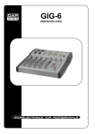
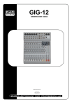
1
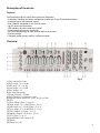
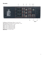
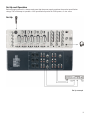
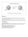
ZoneControl MKII
ORDERCODE D2107
Congratulations!
You have bought a great, innovative product from DAP Audio.
The DAP Audio ZoneControl MKII brings excitement to any venue. Whether you want simple plug-&-play
action or a sophisticated show, this product provides the effect you need.
You can rely on DAP Audio, for more excellent audio products.
We design and manufacture professional audio equipment for the entertainment industry.
New products are being launched regularly. We work hard to keep you, our customer, satisfied.
For more information: [email protected]
You can get some of the best quality, best priced products on the market from DAP Audio.
So next time, turn to DAP Audio for more great audio equipment.
Always get the best -- with DAP Audio !
Thank you!
DAP Audio
DAP Audio ZoneControl MKII™ Product Guide
Warning..…...................................................................................…………………………………………..
Safety-instructions………………………………………………………………………………………….….
Operating Determinations…………………………………………………………………………………….
2
2
3
Description..…..............................................................................……….…………………………………
Features………………………………………………………………………………….………………….….
Overview ..…………………………………………………………………………………….………....…….
Backside.………………………………………………………………………….………....……………..….
4
4
4
5
Installation...............................................................................…...……………………………………..….
6
Set Up and Operation.....................................................................……..…………………………….…..
Set Up ……………….............................................…………………………………...................…….....
9
9
Connection Cables..............................….......................................………..………….…….………….….
10
Maintenance………..............................….......................................………..………….…….………….….
11
Troubleshooting………..............................…................................………..………….…….………….…..
11
Product Specifications.................................................................……………….…….…………………..
12
1
WARNING
CAUTION!
Keep this system away from rain and moisture!
FOR YOUR OWN SAFETY, PLEASE READ THIS USER MANUAL CAREFULLY
BEFORE YOUR INITIAL START-UP!
SAFETY INSTRUCTIONS
Every person involved with the installation, operation and maintenance of this system has to:
be qualified
follow the instructions of this manual
CAUTION! Be careful with your operations.
With a dangerous voltage you can suffer
a dangerous electric shock when touching the wires!
Before you initial start-up, please make sure that there is no damage caused by transportation. Should there
be any, consult your dealer and do not use the system.
To maintain perfect condition and to ensure a safe operation, it is absolutely necessary for the user to follow
the safety instructions and warning notes written in this manual.
Please consider that damages caused by manual modifications to the system are not subject to warranty.
This system contains no user-serviceable parts. Refer servicing to qualified technicians only.
IMPORTANT:
The manufacturer will not accept liability for any resulting damages caused by the non-observance of
this manual or any unauthorized modification to the system.
•
•
•
•
•
•
•
•
•
•
•
•
•
•
Never let the power-cord come into contact with other cables! Handle the power-cord and all
connections with the mains with particular caution!
Never remove warning or informative labels from the unit.
Never use anything to cover the ground contact.
Never leave any cables lying around.
Do not insert objects into air vents.
Do not connect this system to a dimmerpack.
Do not switch the system on and off in short intervals, as this would reduce the system’s life.
Do not open the device and do not modify the device.
Do not drive the inputs with a signal level bigger, than required to drive the equipment to full output.
Do not plug Mics into the console (or stagebox) while Phantom Power is on. Also mute the monitor /
Pa system when turning Phantom Power on or off. Allow the system to adjust for a couple of
seconds, before setting the input gains.
Only use system indoor, avoid contact with water or other liquids.
Avoid flames and do not put close to flammable liquids or gases.
Always disconnect power from the mains, when system is not used. Only handle the power-cord by
the plug. Never pull out the plug by tugging the power-cord.
Always operate the unit with the AC ground wire connected to the electrical system ground.
2
•
•
•
•
•
•
•
•
•
•
•
•
•
•
•
•
Make sure you don’t use the wrong kind of cables or defective cables.
Make sure that the signals into the mixer are balanced, otherwise hum could be created.
Make sure you use DI boxes to balance unbalanced signals; All incoming signals should be clear.
Make sure that the available voltage is not higher than stated on the rear panel.
Make sure that the power-cord is never crimped or damaged. Check the system and the power-cord
from time to time.
In system setup, the amplifier's output power must be 50%-100% more than the loaded
loudspeakers rated power.
Please turn off the power switch, when changing the power cord or signal cable, or select the input
mode switch.
Extreme frequency boosts in connection with a high input signal level may lead to overdriving your
equipment. Should this occur, it is necessary to reduce the input signal level by using the INPUT
control.
To emphasize a frequency range, you don’t necessarily have to move its respective sliding control
upward; try lowering surrounding frequency ranges instead. This way, you avoid causing the next
piece of equipment in your sound path to overdrive. You also preserve valuable dynamic reserve
(“headroom”)
Avoid ground loops! Always be sure to connect the power amps and the mixing console to the same
electrical circuit to ensure the same phase!
If system is dropped or struck, disconnect mains power supply immediately. Have a qualified
engineer inspect for safety before operating.
If the system has been exposed to drastic temperature fluctuation (e.g. after transportation), do not
switch it on immediately. The arising condensation water might damage your system. Leave the
system switched off until it has reached room temperature.
If your Dap Audio device fails to work properly, discontinue use immediately. Pack the unit securely
(preferably in the original packing material), and return it to your Dap Audio dealer for service.
Repairs, servicing and electric connection must be carried out by a qualified technician.
For replacement use fuses of same type and rating only.
WARRANTY: Till one year after date of purchase.
OPERATING DETERMINATIONS
If this system is operated in any other way, than the one described in this manual, the product may suffer
damages and the warranty becomes void.
Any other operation may lead to dangers like short-circuit, burns, electric shock, etc.
You endanger your own safety and the safety of others!
Improper installation can cause serious damage to people and property !
3
Description of the device
Features
The ZoneControl MKII is a Multi Zone mixer from Dap Audio.
• 5 channels, including one special microphone-channel with 3-way Eq and balanced input
• 3 separate zones with separate outputs
• Every channel assignable to one of these zones
• Up to 9 audio-sources mixable
• LED indicators for clear visual level readout
• 3-way tonecontrol on every single zone
• PFL (PreFadeListening) on every channel AND on every zone
• Exclusive design
• Separate master groups, each for a different location
Overview
Fig. 1
1) Gain, range min / max
2) High, range -12 / +12 dB
3) Mid, range -12 / +12 dB
4) Low, range -12 / +12 dB
5) Pan, range L / R
6) Mic Input (balanced)
7) Stereo Channel 1-5 Fader
8) Gain Channel 1-5, range min / max
9) Selection Switch (M2/L1/L2, L3/L4, L5/L6 or L7/L8)
10) PFL
11) Zone Assign (Zone 1, 2 and 3)
12) High, range -12 / +12 dB (Zone 1, 2 or 3)
13) Mid, range -12 / +12 dB (Zone 1, 2 or 3)
14) Low, range -12 / +12 dB (Zone 1, 2 or 3)
15) Pan, range L / R (Zone 1, 2 or 3)
16) Master, range 0 / 10 (Zone 1, 2 or 3)
17) PFL (Zone 1, 2 or 3)
18) Headphone Level, range 0 /10
19) Phone
20) Power On / Off
4
Backside
Fig. 2
21) Balanced XLR Output for Zone 1, 2 or 3 (L / R)
22) Unbalanced L/R and Rec Out L/R for Zone 1, 2 or 3
23) Light to Sound for Zone 1, 2 or 3
24) For CH5; L8 (L/R) and L7 (L/R)
25) For CH4; L6 (L/R) and L5 (L/R)
26) For CH3; L4 (L/R) and L3 (L/R)
27) For CH2; L2 (L/R) and L1 (L/R)
28) Balanced 1/4“ jack for Mic 2
29) Ground
5
Installation
Remove all packing materials from the ZoneControl MKII. Check that all foam and plastic padding is
removed. Connect all cables.
Always disconnect from electric mains power supply before cleaning or servicing.
Damages caused by non-observance are not subject to warranty.
1. GAIN
Mic Channel input level is determined by the Gain control.
With the Gain control you can adjust the MIC input-sensitivity, while optimally
matching the incoming signals to the mixer’s internal operation level. When dealing
with very low input levels (example vocal recordings or distant sound sources) the
high gain is extremely profitable.
How to set the Input level:
1) Set the gain control and the corresponding channel fader to their minimum setting.
2) Connect the desired sound source (CD player, microphone, ect) to the
corresponding MIC input.
3) Play the sound source at its highest volume setting; respectively, sing or speak as
loud as possible directly into the microphone.
4) While doing so, adjust the input level using the gain control, so that during the
loudest passages the PEAK LED is just not lit, but the SIGNAL-LED lights
constantly.
This basic channel setting leaves you at least 8dB headroom. This means, you have
at least 8dB before signal clipping. If you want to make further adjustments to the
channel’s EQ setting, you should repeat step 3 and 4 again.
2 / 3 / 4. EQ HIGH / MID / LOW
The mixer’s Equalizer section allows shaping of the incoming audio signal. All mono
input channels are fitted with 3-band EQ. The upper (2) and lower (4) shelving
controls have their frequencies fixed at 12 Khz and 80 Hz respectively. The Mid range
control (3) has a peaking response frequency at 2.5 Khz. All 3 bands have up to 12
dB cut and boost, with a centre detent for “OFF”. Turning the Equalizer level control to
the right amplifies the frequency range, turning to the left attenuates the signal. Minor
changes to the Equalizer control usually produce the best results. Try to avoid
excessive enhancement of the MID band.
5. PAN
By using the PAN control you can change the input signal’s position within the stereo
image. When the PAN control is set to center position, the audio signal is equal for
both the left and right buss.
6
6. MIC
Electronically balanced XLR-type inputs for connecting low-impedance microphones. The input provides
extremely low noise and low hum signal processing. When connecting a microphone make sure that the pin
assignment is correct. Always make sure to read the manual of the microphone you want to connect. The
XLR-inputs are not suitable for connecting an additional mixing console, FX-unit, etc. You have to use the
LINE-inputs, when connecting this kind of equipment.
Note: When connecting signal sources, please make sure that the corresponding channel faders and
the master faders are at their minimum settings. Otherwise unpleasant plug-in noise can occur.
7. Channel Fader
A high-quality true logarithmic 60mm fader, which controls the volume of a single channel and to establish
an accurately proportioned mix of all input signals. The channel faders should be positioned within the range
of -5dB to 0dB, leaving you with sufficient room to allow precise matching of differences in the channel’s
level settings. The overall volume is set with the master fader. Even though the channel faders offer an
additional gain of +10dB, it is better not to exceed the +5dB position.
8. GAIN
Mic Channel input level is determined by the Gain control.
With the Gain control you can adjust the MIC input-sensitivity, while optimally matching the incoming signals
to the mixer’s internal operation level. When dealing with very low input levels (example vocal recordings or
distant sound sources) the high gain is extremely profitable.
9. Selection Switch (M2/L1/L2, L3/L4, L5/L6 or L7/L8)
With this switch you can select multiple devices you have connected to your ZoneControl. You can control
up to 8 different devices.
10. PFL
The PFL button (pre fade listening) is designed to override the main signal, so although an individual
channel is heard, it is not in complete isolation. If you push the PFL button, regardless of the Aux rotary
control, you will get the complete signal in your headphone/monitors. This is useful, because the recording
engineer hears some of the main signal. So the channel is not only heard, but also in context. Pressing this
button assigns a channel’s audio signal to the PFL bus. Simultaneously assigning more than one channel to
the PFL bus is possible, while the individual channel’s volume fader setting is not recognized (PRE FADER
LISTEN). Once a PFL button is pressed, the master display automatically enters PFL/PGM mode. This
allows you setting a signal’s correct level or making special EQ-adjustments without the need of including it
in the main mix.
11. Zone Assign (Zone 1, 2 and 3)
You can send the output signal to each of the 3 amplifiers.
7
You can adjust High, Mid, Low, Pan, Master and PFL per Zone individually. Thus giving you enough room to
play with all 3 output channels.
12 / 13 / 14. EQ HIGH / MID / LOW
The mixer’s Equalizer section allows shaping of the incoming audio signal. All mono input channels are
fitted with 3-band EQ. The upper (12) and lower (14) shelving controls have their frequencies fixed at 12
Khz and 80 Hz respectively. The Mid range control (13) has a peaking response frequency at 2.5 Khz. All 3
bands have up to 12 dB cut and boost, with a centre detent for “OFF”. Turning the Equalizer level control to
the right amplifies the frequency range, turning to the left attenuates the signal. Minor changes to the
Equalizer control usually produce the best results. Try to avoid excessive enhancement of the MID band.
15. PAN
By using the PAN control you can change the input signal’s position within the stereo image. When the PAN
control is set to center position, the audio signal is equal for both the left and right buss.
16. MASTER
By using the MASTER control you can change the overall output signal’ of an individual Zone.
17. PFL
The PFL button (pre fade listening) is designed to override the main signal, so although an individual
channel is heard, it is not in complete isolation. If you push the PFL button, regardless of the Aux rotary
control, you will get the complete signal in your headphone/monitors. This is useful, because the recording
engineer hears some of the main signal. So the channel is not only heard, but also in context. Pressing this
button assigns a channel’s audio signal to the PFL bus. Simultaneously assigning more than one channel to
the PFL bus is possible, while the individual channel’s volume fader setting is not recognized (PRE FADER
LISTEN). Once a PFL button is pressed, the master display automatically enters PFL/PGM mode. This
allows you setting a signal’s correct level or making special EQ-adjustments without the need of including it
in the main mix.
18. Phones
This control allows you to adjust the headphones’ volume. Phones controls 19, range 0-10
Caution: Depending on the type of headphones connected to the phones jack, the Powermix is capable of
producing very high output levels via the phones output. Therefore, make sure to turn the control all the way
to the left (minimum setting) before connecting the headphones.
Be aware of the fact that listening to loud sound pressure levels over a longer period of time leads to
hearing-damage!
19) Phones
You can connect a pair of headphones with an impedance of 32 - 600 Ohm to this Stereo Phones jack.
Balanced 1/4” TRS socket, wired as Tip=left, Ring=right and sleeve = ground.
20) Power On / Off
8
Set Up and Operation
Before plugging the unit in, always make sure that the power supply matches the product specification
voltage. Do not attempt to operate a 120V specification product on 230V power, or vice versa.
Set Up
Set Up example
9
Connection Cables
Take care of the connector cables, always holding them by the connectors and avoiding knots and twists
when coiling them: This gives the advantage of increasing their life and reliability, which is always to your
advantage.
Periodically check that your cables are in good condition, that they are correctly wired and that all their
contacts are perfectly efficient: a great number of problems (faulty contacts, ground hum, discharges, etc.)
are caused entirely by using unsuitable or faulty cables.
Headphones
Unbalanced mono 1/4” jack plug
Balanced mono 1/4” jack plug
Compensation of interference with balanced connections
10
Maintenance
The DAP Audio ZoneControl MKII requires almost no maintenance. However, you should keep the unit
clean. Disconnect the mains power supply, and then wipe the cover with a damp cloth. Do not immerse in
liquid. Do not use alcohol or solvents.
Keep connections clean. Disconnect electric power, and then wipe the DMX and audio connections with a
damp cloth. Make sure connections are thoroughly dry before linking equipment or supplying electric power.
Troubleshooting
DAP Audio ZoneControl MKII
This troubleshooting guide is meant to help solve simple problems. If a problem occurs, carry out the steps
below in sequence until a solution is found. Once the unit operates properly, do not carry out following
steps.
1. If the device does not operate properly, unplug the device.
2. Check power from the wall, all cables, the fuse, etc.
3. If all of the above appears to be O.K., plug the unit in again.
4. If nothing happens after 30 seconds, unplug the device.
5. Return the device to your DAP Audio dealer.
11
Product Specification
Model: DAP Audio ZoneControl MKII
Power
230 V
Dimensions
480 x 120 x 133 mm (LxWxH); 3HE
Weight
3.86 Kg
Mono Inputs
Mic Input
Frequency response
Distortion (THD & N)
electronically balanced
10 Hz to 60 KHz ±3 dB
0.007% at ±20 dBu, 1 Khz, Bandwidth 80 KHz
Stereo Inputs
Line Input
Bandwidth
Distortion (THD & N)
unbalanced
10 Hz to 55 KHz ±3 dB
0.007% at +4dBu, 1Khz, Bandwidth 80 KHz
Equalization
Hi Shelving
Mid EQ
Low Shelving
12 KHz +/-12 dB
2.5 KHz +/-12 dB
80 Hz +/-12 dB
Master Mix Section
Noise
Max Output
Bus noise, fader 0 dB, channels muted:
Gain: - 88.5 dBr (ref: +4dBu)
+22 dBu balanced XLR, +22 dBu unbalanced cinch
Light To Sound 1/4” jack +22dBu
Design and product specifications are subject to change without prior notice.
12
2005 Dap Audio.