1
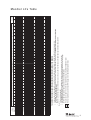
CALIBRATION due
07
90
0-
09
08
0
Instruction Manual
4
5
3
40
2
20
1
0
60
10
2
0 lbf/in
bar
07900-09080
Speed Fastening Applications
B ro a c h L o a d Te s t P o w e r To o l
80
6
0
7
Contents
Safety Rules
4
Tool Specifications
5
Intent of Use
5
Putting into Service
Air Supply
Loading the Tool
Cursor
Nose Equipment
Operating Procedure
6
6
6
6
7
Air Pressure Graph vs Broach Load
8
Mandrel Life Table
9
Warranty
Avdel UK Limited installation tools carry a 12 month warranty against defects caused
by faulty materials or workmanship, the warranty period commencing from the date of
delivery confirmed by invoice or delivery note.
The warranty applies to the user/purchaser when sold through an authorised outlet,
and only when used for the intended purpose. The warranty is invalidated if the
installation tool is not serviced, maintained and operated according to the instructions
contained in the Instruction and Service Manuals.
In the event of a defect or failure, and at its sole discretion, Avdel UK Limited
undertakes only to repair or replace faulty components.
Avdel UK Limited policy is one of continuous product development and improvement and we reserve the right to change the specification of any product without prior notice.
3
Safety Rules
This instruction manual must be read with particular attention to the following safety rules, by any person
operating this tool.
1
Do not use outside the design intent.
2
Do not use equipment with this tool/machine other than that recommended and supplied by Avdel UK Limited.
3
Any modification undertaken by the customer to the tool/machine or any equipment supplied by Avdel UK Limited or their
representatives, shall be the customer’s entire responsibility. Avdel UK Limited will be pleased to advise upon any proposed
modification.
4
The tool/machine must be maintained in a safe working condition at all times and examined at regular intervals for damage and
function by trained competent personnel. Any dismantling procedure shall be undertaken only by personnel trained in Avdel UK
Limited procedures. Do not dismantle this tool/machine without prior reference to the maintenance instructions. Please contact
Avdel UK Limited with your training requirements.
5
The tool/machine shall at all times be operated in accordance with relevant Health and Safety legislation. In the U.K. the “Health
and Safety at Work etc. Act 1974” applies. Any question regarding the correct operation of the tool/machine and operator safety
should be directed to Avdel UK Limited.
6
The precautions to be observed when using this tool/machine must be explained by the customer to all operators.
7
Always disconnect the airline from the tool/machine inlet before attempting to adjust, fit or remove a nose assembly.
8
Do not operate a tool/machine that is directed towards any person(s).
9
Always adopt a firm footing or a stable position before operating the tool/machine.
10 Ensure that vent holes do not become blocked or covered.
11 Do not operate the tool if it is not fitted with a complete nose assembly or swivel head unless specifically instructed otherwise.
12 When using the tool, the wearing of safety glasses is required both by the operator and others in the vicinity to protect against
fastener ejection, should a fastener be placed ‘in air’. We recommend wearing gloves if there are sharp edges or corners on the
application.
13 Take care to avoid entanglement of loose clothes, ties, long hair, cleaning rags etc. in the moving parts of the tool which should
be kept dry and clean for best possible grip.
14 When carrying the tool from place to place keep hands away from the trigger/lever to avoid inadvertent start up.
15 The combination of fastener, mandrel, hole size and sheet thickness shall be in accordance with specifications set by Avdel UK
Limited.
16 The cylinder of the tool must be free to move without risk of hitting or trapping the operator.
I M P O R TA N T
While a small amount of wear and marking will naturally occur through normal and correct use of mandrels,
they must be regularly examined for excessive wear and marking, with particular attention to the head
diameter, the tail jaw gripping area of the shank or heavy pitting of the shank and any mandrel distortion.
Mandrels which fail during use could forcibly exit the tool. It is the customer's responsibility to ensure that
mandrels are replaced before any excessive levels or wear and always before the maximum recommended
number of placings. Contact your Avdel UK Limited representative who will let you know what that figure is by
measuring the broach load of your application with a calibrated test tool. These tools can also be purchased
under Part Number 07900-09080, supplied with all necessary information for testing in this manual.
4
Specification
Air Pressure
Maximum
7 bar
Free Air Volume Required
@ 5.5 bar
1.72 litres
Noise Level
Less than
70 dB(A)
Weight
Without nose equipment
3.0 kg
Vibration
Less than
2.5 m/s2
Intent of Use
This particular test tool is to be used solely with Avdel® speed fasteners supplied by Avdel®. The precise list of fasteners appears in
the mandrel life table page 9. The tool is supplied without any nose equipment as it is fundamental that this tool is used fitted with the
exact same nose equipment as that used on the placing tool you have selected to place your fasteners. Tools can be purchased under
part number 07900-09080 or you may contact your local Avdel representative to test your application.
The test tool can be used to define the ideal combination of tool/nose equipment/fastener for your application and in any case MUST
be used prior to the actual placing tool in order to define the broach load exerted on the mandrel when placing a fastener in the
application. IT IS ESSENTIAL TO ESTABLISH THE BROACH LOAD TO PREVENT OVER-USAGE OF MANDRELS AND RISK BREAKAGE
AND INJURY.
The intensity of the broach load will vary with the level of interference between the diameters of the fastener, of the mandrel head and
of the hole in the application as well as with the thickness of the application. SPEED FASTENING DEMANDS RIGOROUS OBSERVATION
OF RECOMMENDATIONS laid down in fastener technical data sheets and in the selection process of nose equipment laid down in
instruction manuals.
When putting the test tool into operation, its gauge will display the air pressure at which a particular fastener will place in a specific
application with defined nose equipment.
The graph on page 8, will allow you to convert that air pressure (bars) into a broach load (Newtons) which in turn can be
translated, using the table page 9, into a maximum safe number of placings for that series of fasteners with the exact
same nose equipment you will use with your placing tool AND in random samples of your actual application.
5
Putting into Service
Air Supply
This tool operates with compressed air at a maximum pressure of 7 bar. We recommend that you temporarily make use of the air
supply set up for your actual placing tool with precautions as described in the instruction manual for your placing tool.
L o a d i n g t h e To o l
The procedure for loading the tool with fasteners and for fitting the nose equipment to the tool are integral. Refer to the instruction
manual for your specific placing tool EXCEPT FOR 1.6MM (1/16”) AVLUG® WHICH SHOULD BE LOADED ONE AT A TIME PER TEST AS
THE TEST TOOL CANNOT EXACTLY EMULATE THE 07176 PLACING TOOL USED FOR PLACING THIS FASTENER.
Cursor
I M P O R TA N T
It is essential to check that the cursor orientation before attempting to operate the tool.
To avoid complete dismantling of the tool check the orientation
of the cursor before fitting the nose equipment to the tool. If
fitted incorrectly, the cursor will not allow feeding of the
fasteners. When fitted the correct way round, the cursor will
easily slide out of the barrel when a mandrel is pushed into its
centre then pulled back. To reverse the orientation of the
cursor, refer to the instruction manual for your particular
placing tool. The sprung loaded, slightly concave, end of the
cursor should point towards the front of the tool as shown
right.
CURSOR
SPRING
LOADED END
TOOL
BARREL
NOSE
JAWS
Nose Equipment
Fit the same mandrel, follower spring and nose jaws as you intend to fit on the tool which you have selected to place your fasteners
following the ‘tool loading’ instructions in the manual for that tool.
I M P O R TA N T
It is essential that the correct nose equipment is fitted to the tool to ensure both effective placing of the
fastener and SAFE operation of the tool.
6
Putting into Service
O p e r a t i n g P ro c e d u r e
READ THE SAFETY INSTRUCTIONS page 4 carefully.
•
•
•
•
•
•
•
•
•
•
Connect the test tool to the air supply.
Set the gauge on the test tool to zero actuating the
trigger to ensure a true reading.
Fit the exact same nose equipment to the test tool as
you intend to use on the tool you will be using to place
the fasteners in your application and as recommended in
the instruction manual for your specific tool. Note that
when testing 1/16” Avlug® fasteners NO POD must be
used. A single fastener must be fed at a time. To fit the
nose equipment, follow the ‘Loading the tool’ procedure
in the instruction manual for your placing tool.
Switch on tail jaws by operating slider valve.
Offer the protruding fastener into the application applying
a little pressure to ensure that the fastener head rests
against the application (This is crucial to obtain a true
reading).
Hold the trigger in and SLOWLY raise the air supply pressure until the fastener places. Keeping the trigger held, read the air
pressure off the gauge before releasing the trigger.
The mandrel is pulled through the fastener which is formed into the application.
Remove the application. The next fastener will automatically be presented through the front nose jaws, ready for placing.
The highest of at least 10 readings should be used.
As the test tool was calibrated, the graph on page 8 will convert the air pressure reading in bars into a broach load in newtons.
TO CONVERT THE BROACH LOAD INTO A MAXIMUM NUMBER OF FASTENER PLACINGS PER MANDREL
•
•
Locate your broach load reading on the scale at the top of the table on page 9 and on the left-hand side, find the line with your
fastener (name and size).
The maximum recommended number of fastener placings with one mandrel will be shown where they intersect. THIS NUMBER OF
PLACINGS MUST NOT BE EXCEEDED. In case of doubt contact Avdel Fastening Systems for advice.
I M P O R TA N T
The test tool MUST be returned to Avdel UK Limited at minimum every 6 months for re-calibration.
A new manual with an updated air pressure versus broach load graph will be supplied in English and in the
official language of your country if EC regulations apply.
NO MAINTENANCE WHATSOEVER MAY BE CARRIED OUT ON THIS TOOL BY ANYONE OTHER THAN
SPECIFICALLY TRAINED AND DESIGNATED AVDEL PERSONNEL. FOLLOWING MAINTENANCE, THE TOOL
MUST BE RE-CALIBRATED PRIOR TO FURTHER USE.
7
A i r P re s s u re G r a p h v s B ro a c h L o a d
8
489
110 /
50000
2.5mm Avtronic
50000
42600
-
50000
-
50000
50000
50000
-
50000
-
3/32 Grovit
2.5mm Avsert
4-40 UNC Avsert
1/8 Avlug
2.8mm Avtronic
1/8 Chobert
1/4 Chobert
6mm Briv
3/16 Briv (St.Steel)
3/16 Grovit
3/16 Chobert
3/16 Briv
5/32 Briv (St.Steel)
5/32 Grovit
5/32 Chobert
4.8mm Rivscrew
4.0mm Rivscrew
5/32 Briv
3.5mm Rivscrew
1/8 Briv (St.Steel)
1/8 Briv
6-32 UNC Avsert
3mm Avsert
1/8 Grovit
50000
50000
50000
538
120 /
50000
50000
-
50000
-
50000
50000
28200
28200
28200
28200
50000
50000
49000
20900
20900
28800
X
582
130 /
50000
50000
50000
33500
33500
33500
33500
50000
50000
50000
25100
25100
32500
13000
-
-
-
50000
50000
50000
-
35100
50000
35100
41700
35100
35100
50000
50000
20400
20400
20400
20400
40300
37200
35100
14600
14600
23400
X
672
150 /
41700
41700
41700
50000
50000
23400
23400
23400
23400
50000
43200
38900
16200
16200
25100
X
627
140 /
-
50000
-
50000
29500
29500
29500
29500
50000
48400
17400
17400
17400
17400
35900
33900
32400
13200
13200
16000
X
717
160 /
50000
50000
-
50000
50000
-
34700
-
50000
22600
22600
22600
22600
38500
35900
12900
12900
12900
12900
30900
28800
26600
8710
8710
X
X
806
180 /
-
50000
-
50000
26000
26000
26000
26000
44200
39800
15000
15000
15000
15000
33300
31600
29500
10400
10400
10200
X
762
170 /
-
50000
50000
-
30200
50000
44200
20200
20200
20200
20200
35500
34500
10800
10800
10800
10800
28200
26300
23700
7240
7240
X
X
851
190 /
35100
35100
-
48400
-
32400
32400
32400
20400
41000
33100
12200
12200
12200
12200
27900
25700
6400
6400
6400
6400
18000
14500
11200
X
X
X
X
1008
225 /
48400
44200
44200
-
26600
50000
38500
18000
18000
18000
18000
33100
30900
9300
9300
9300
9300
25700
23200
20400
6110
6110
X
X
896
200 /
-
26600
26600
25100
25100
25100
15800
34600
28200
9660
9660
9660
9660
21900
19100
X
X
X
X
6920
X
X
X
X
X
X
1120
250 /
-
21900
21900
20200
20200
20200
12200
30500
22900
7080
7080
7080
7080
14600
10800
X
X
X
X
X
X
X
X
X
X
X
1232
275 /
50000
50000
50000
-
50000
50000
50000
-
14500
14500
13200
13200
13200
7410
20900
8510
X
X
X
X
X
X
X
X
X
X
X
X
X
X
X
X
X
1456
325 /
-
17600
17600
16400
16400
16400
9550
26000
16800
5250
5250
5250
5250
X
X
X
X
X
X
X
X
X
X
X
X
X
1344
300 /
X
X
X
X
X
X
X
X
X
X
X
X
X
X
X
X
X
X
1568
350 /
-
47900
47900
47900
25100
11700
11700
10700
10700
10700
5820
15700
Tool Broach Load (lbf / N)
-
38500
38500
38500
22400
9660
9660
8710
8710
8710
X
8900
X
X
X
X
X
X
X
X
X
X
X
X
X
X
X
X
X
X
1680
375 /
35900
35900
35900
50000
50000
500 /
27500
27500
27500
19700
19700
19700
10500
X
X
X
X
X
X
X
X
X
X
X
X
X
X
X
X
X
X
X
X
X
X
X
X
X
2240
550 /
22600
22600
22600
15500
15500
15500
7590
X
X
X
X
X
X
X
X
X
X
X
X
X
X
X
X
X
X
X
X
X
X
X
X
X
2464
18400
18400
18400
12200
12200
12200
5620
X
X
X
X
X
X
X
X
X
X
X
X
X
X
X
X
X
X
X
X
X
X
X
X
X
2688
600 /
15000
15000
15000
9660
9660
9660
X
X
X
X
X
X
X
X
X
X
X
X
X
X
X
X
X
X
X
X
X
X
X
X
X
X
2912
650 /
12200
12200
12200
7500
7500
7500
X
X
X
X
X
X
X
X
X
X
X
X
X
X
X
X
X
X
X
X
X
X
X
X
X
X
3136
700 /
10500
10500
10500
6100
6100
6100
X
X
X
X
X
X
X
X
X
X
X
X
X
X
X
X
X
X
X
X
X
X
X
X
X
X
3360
750 /
8700
8700
8700
X
X
X
X
X
X
X
X
X
X
X
X
X
X
X
X
X
X
X
X
X
X
X
X
X
X
X
X
X
3584
800 /
7000
7000
7000
X
X
X
X
X
X
X
X
X
X
X
X
X
X
X
X
X
X
X
X
X
X
X
X
X
X
X
X
X
3808
850 /
Locate your broach load reading on the scale at the top of the table and on the left-hand side, find the line with your fastener (name & size).
The maximum recommended number of fastener placings with one mandrel will be shown where they intersect. THIS NUMBER OF PLACINGS MUST NOT BE EXCEEDED.
In case of doubt contact Avdel UK Limited
Where the achieved broach load is in between two values on the scale at the top of the table, use the higher table value to determine the mandrel life
Broach Load is too high - If close to the lowest number of placings, contact Avdel UK Limited for advice
Never use mandrels to place more than 50000 placings or more than the highest number shown
X
-
•
Note
• # Denotes using long mandrel
• 3/16 Briv, 6mm Briv & 1/4 Chobert - At higher broach loads, tool air pressure may need to be Circa 90PSI
• Any application which results in a broach load in excess of that stated for a mandrel life of 5000 rivet placings
(Refer to right hand column of table) should be referred to Avdel UK Limited.
•
•
24300
24300
24300
13600
5190
5190
X
X
X
X
X
X
X
X
X
X
X
X
X
X
X
X
X
X
X
X
X
X
X
2016
450 /
-
32700
32700
32700
18600
7760
7760
7000
7000
7000
X
X
X
X
X
X
X
X
X
X
X
X
X
X
X
X
X
X
X
X
1792
400 /
MAXIMUM NUMBER OF FASTENER PLACINGS PER MANDREL
TO CONVERT THE BROACH LOAD INTO A MAXIMUM OF FASTENERS PLACINGS PER MANDREL
42600
42600
42600
50000
3/32 Avlug
30500
3/32 Chobert
# 3/32 Avlug
50000
50000
3mm Rivscrew
30500
50000
2.8mm Rivscrew
36300
20000
45700
445
1/16 Avlug
3/32 Briv
100 /
26000
(for which the
mandrel is used)
Fastener
5500
5500
5500
X
X
X
X
X
X
X
X
X
X
X
X
X
X
X
X
X
X
X
X
X
X
X
X
X
X
X
X
X
4032
900 /
X
X
X
X
X
X
X
X
X
X
X
X
X
X
X
X
X
X
X
X
X
X
X
X
X
X
X
X
X
X
X
X
MAX. LOAD AT
922
922
922
784
784
784
622
456
456
443
443
443
362
390
338
305
305
305
305
295
291
242
242
242
242
258
244
241
214
214
177
127
lbsf
4101
4101
4101
3488
3488
3488
2767
2028
2028
1971
1971
1971
1610
1735
1504
1357
1357
1357
1357
1312
1294
1077
1077
1077
1077
1148
1085
1072
952
952
787
565
N
5000 PLACINGS
M a n d re l L i f e Ta b l e
9
Notes
10
Declaration of Conformity
We, Avdel UK Limited, Watchmead Industrial Estate, Welwyn Garden City, Herts, AL7 1LY
declare under our sole responsibility that the product:
Model: Broach Load Test Power Tool
Serial No.
................................................
to which this declaration relates is in conformity with the following standards:
EN ISO 12100 - parts 1 & 2
BS EN ISO 8662 - part 6
BS EN ISO 11202
BS EN ISO 3744
BS EN 982
ISO EN 792 part 13 - 2000
BS EN 983
following the provisions of the Machine Directive 98/37/EC
A. Seewraj - Product Engineering Manager - Automation Tools
Date of issue
This box contains a power tool which is in
conformity with Machines Directive
98/37/EC. The ‘Declaration of Conformity’ is
contained within.
GERMANY
SOUTH KOREA
Acument Australia Pty Ltd.
Avdel Deutschland GmbH
Acument Korea Ltd.
891 Wellington Road
Klusriede 24
212-4, Suyang-Ri,
Rowville, Victoria 3178
30851 Langenhagen
Silchon-Eup, Kwangju-City,
Tel: +61 3 9765 6400
Tel: +49 (0) 511 7288 0
Kyunggi-Do, Korea, 464-874
Fax: +61 3 9765 6445
Fax: +49 (0) 511 7288 133
Tel: +82 31 798 6340
Email: [email protected]
Email: [email protected]
Fax: +82 31 798 6342
CANADA
ITALY
Avdel Canada, a Division of Acument
Avdel Italia S.r.l.
SPAIN
Canada Limited
Viale Lombardia 51/53
Avdel Spain S.A.
87 Disco Road
20047 Brugherio (MI)
C/ Puerto de la Morcuera, 14
Rexdale
Tel: +39 039 289911
Poligono Industrial Prado Overa
Ontario M9W 1M3
Fax: +39 039 2873079
Ctra. de Toledo, km 7,8
Tel: +1 416 679 0622
Email: [email protected]
28919 Leganés (Madrid)
Email: [email protected]
Fax: +1 416 679 0678
Tel: +34 (0) 91 3416767
Email: [email protected]
JAPAN
Fax: +34 (0) 91 3416740
Acument Japan Kabushiki Kaisha
Email: [email protected]
CHINA
Center Minami SKY,
Acument China Ltd.
3-1 Chigasaki-Chuo, Tsuzuki-ku,
UNITED KINGDOM
RM 1708, 17/F., Nanyang Plaza,
Yokohama-city, Kanagawa Prefecture
Avdel UK Limited
57 Hung To Rd., Kwun Tong
Japan 224-0032
Pacific House
Hong Kong
Tel: +81 45 947 1200
2 Swiftfields
Tel: +852 2950 0631
Fax: +81 45 947 1205
Watchmead Industrial Estate
Fax: +852 2950 0022
Email: [email protected]
Welwyn Garden City
Email: [email protected]
Hertfordshire
SINGAPORE
AL7 1LY
FRANCE
Acument Asia Pacific (Pte) Ltd.
Tel: +44 (0) 1707 292000
Avdel France S.A.S.
#05-03/06 Techlink
Fax: +44 (0) 1707 292199
33 bis, rue des Ardennes
31 Kaki Bukit Road 3
Email: [email protected]
BP4
Singapore, 417818
75921 Paris Cedex 19
Tel: +65 6840 7431
USA
Tel: +33 (0) 1 4040 8000
Fax: +65 6840 7409
Avdel USA LLC
Fax: +33 (0) 1 4208 2450
Email: [email protected]
614 NC Highway 200 South
Email: [email protected]
Stanfield,
North Carolina 28163
Tel: +1 704 888-7100
Fax: +1 704 888-0258
Email: [email protected]
Manual No.
Issue
AA
03/008
06-02-03
07900-00683
AB
03/338
06-10-03
AC
07/176
24-05-07
Avdel® is a trademark of Avdel UK Limited.
www.avdel-global.com
Change Note No.
Date
© Avdel UK Limited 2007
AUSTRALIA