1
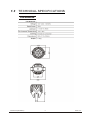
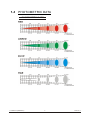
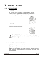
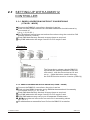
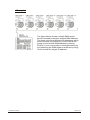
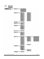
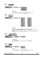
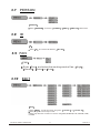
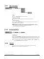
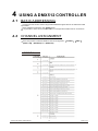
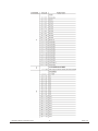
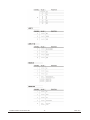
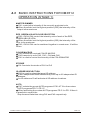
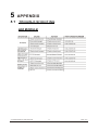
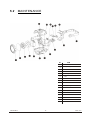
11
T
ABLE OF CONTENTS
PART 1 PRODUCT (GENERAL)....................................................1.
1.1--PRODUCT INTRODUCTION.........................................................1.
1.2--PRODUCT FEATURES.................................................................1.
1.3--TECHNICAL SPECIFICATIONS.....................................................2.
1.4--PHOTOMETRIC DATA..................................................................3.
1.5--SAFETY WARNING......................................................................4.
PART 2 INSTALLATION...............................................................5.
2.1--MOUNTING...................................................................................5.
2.2--POWER CONNECTION..................................................................5.
2.3--SETTING UP WITH A DMX512 CONTROLLER.................................6.
2.3-1--DMX512 ADDRESSING WITHOUT ID ADDRESSING......................................6.
2.3-2--DMX512 ADDRESSING WITH ID ADDRESS..................................................6.
PART 3 DISPLAY PANEL OPERATION.........................................8.
3.1--BASIC..........................................................................................8.
3.2--MENU..........................................................................................9.
3.3--STATIC......................................................................................1 0.
3.4-- AUTO .........................................................................................10.
3.5--ADDRESS..................................................................................10.
3.6--RUN...........................................................................................10.
3.7-- PERSON ...................................................................................1 1.
3.8--ID.............................................................................................. 11.
3.9--FAN........................................................................................... 11.
3.10--EDIT ........................................................................................11.
3.11--SETTINGS ...............................................................................12.
3.12--PASSWORD .............................................................................12.
3.13--SAVE .......................................................................................12.
PART 4 USING A DMX512 CONTROLLER....................................13.
4.1--BASIC ADDRESSING.................................................................13.
4.2--CHANNEL ASSIGNMENT............................................................13.
4.3--BASIC INSTRUCTIONS FOR DMX512 OPERATION (STAGE 1).....16.
PART 5 APPENDIX..................................................................... 17.
5.1--TROUBLE SHOOTING...............................................................17.
5.2--MAINTENANCE........................................................................ 18.
1
PRODUCT (GENERAL)
1.1
PRODUCT INTRODUCTION
This product is designed for indoor use. Suitable applications include
wash or effect lighting for architectural, stage or nightclub applications.
This product can also be installed for use in signage and advertising using
the dynamic functions available with DMX512 control. Direct input of
DMX512 signal allows the units to be controlled from any DMX512
controller. This product can be operated as a single unit or in multiple units
for large applications.
The specially developed controller that allows the product to be controlled
independent of the DMX512 controller enables the user to create and edit a
wide range of custom programs. All programs can be touch-button
displayed or scheduled to START and END at scheduled times. When
programs have been created or edited in the controller, it is also possible to
trigger these programs using the DMX IN function when connected to a
DMX512 controller.
1.2
PRODUCT FEATURES
LED FIXTURE
* RGB Dimmer 0-100%
* Strobe
* Automatic programs
* LCD display
* Display control 'lock-out'
* Direct DMX512 input
* Independant ID address
* Stand-alone/ Slave
1 PRODUCT(GENERAL)
1
2009.12.9
1.3
TECHNICAL SPECIFICATIONS
LED MODULE
1 PRODUCT(GENERAL)
2
2009.12.9
1.4
PHOTOMETRIC DATA
PHOTOMETRIC DATA
1 PRODUCT(GENERAL)
3
2009.12.9
1.5
SAFETY WARNING
IMPORTANT
ALWAYS READ THE USER MANUAL BEFORE OPERATION.
PLEASE CONFIRM THAT THE POWER SUPPLY STATED ON THE
PRODUCT IS THE SAME AS THE MAINS POWER SUPPLY IN YOUR
AREA.
This product must be installed by a qualified professional.
Always operate the equipment as described in the user manual.
A minimum distance of 0.5m must be maintained between the
equipment and combustible surface.
The product must always be placed in a well ventilated area.
Always make sure that the equipment is installed securely.
DO NOT stand close to the equipment and stare directly into the LED
light source.
Always disconnect the power supply before attempting and
maintenance.
Always make sure that the supporting structure is solid and can
support the combined weight of the products.
The earth wire must always be connected to the ground.
Do not touch the power cables if your hands are wet.
ATTENTION
This product left the place of manufacture in perfect condition.
In order to maintain this condition and for safe operation, the
user must always follow the instructions and safety warnings
described in this user manual.
Avoid shaking or strong impacts to any part of the equipment.
Make sure that all parts of the equipment are kept clean and
free of dust.
Always make sure that the power connections are connected
correct and secure.
If there is any malfunction of the equipment, contact your
distributor immediately.
When transferring the product, it is advisable to use the
original packaging in which the product left the factory.
Shields, lenses or ultraviolet screens shall be changed if they
have become damaged to such an extent that their
effectiveness is impaired.
The lamp (LED) shall be changed if it has become damaged or
thermally deformed.
1 PRODUCT(GENERAL)
4
2009.12.9
2
2.1
INSTALLATION
MOUNTING
HANGING
The LED PAR can be mounted in a hanging position using the
supporting bracket. The bracket should be secured to the mounting
truss or structure using a standard mounting clamp. Please note
that when hanging the unit a safety cable should also be used.
UPRIGHT
The LED PAR can be mounted in an upright or sitting
position using the supporting brackets.
The LED MODULE can be mounted at any angle and in any
position. It is possible to further adjust the angle of the LED
MODULE using the two adjustment knobs located on the side of
the fixture.
2.2
POWER CONNECTIONS
@ 220V: 40 units may be connected in series
@120V: 20 units may be connected in series
Note: As this fixture's DMX signal cable connection had been changed to
Parallel connection, so if over 30 units to be connected, then a DMX signal
amplifier is needed.
2 INSTALLATION
5
2009.12.9
2.3
SETTING UP WITH A DMX512
CONTROLLER
2.3-1 DMX512 ADDRESSING WITHOUT ID ADDRESSING
(STAGE 1 MODE)
Connect the DMX512 controller to the units in series.
Each unit has 9 DMX channels so the DMX Addresses should increase by
increments of
9 (e.g. 1,10,19,28...)
The ID address has not been set so therefore when using the controller Ch9
must be inactive ( CH9=0 ).
Each DMX Address may be used as many times as required.
Any DMX address in the range from 001 to 512 may be used.
Example:
The figure above shows a simple DMX512
layout with the starting address of the first
unit set at 1, with the second set at 10 and
so on... (Note that when used in this way,
the CH9 ID function must be inactive (CH9=0))
2.3-2 DMX512 ADDRESSING WITH ID ADDRESS (STAGE 1 MODE)
Connect the DMX512 controller to the units in series
Each unit has 9DMX channels so the DMX Addresses should increase by
increments of 9 (e.g. 1,10,19,28...)
Each DMX Address may be used as many times as required.
Any DMX address in the range from 001 to 512 may be used.
Each DMX address may carry up to 66 separate ID addresses.
ID should be set in the menu on each unit in ascending values
(i.e. 1,2,3...)
ID addresses are accessible from Ch9 on the DMX512 controller.
2 INSTALLATION
6
2009.12.9
Example:
The figure above shows a simple DMX layout
which has used three units at each DMX address.
The three units have different ID addresses which
allows the user to collectively control the whole
group of units at that DMX address by setting
CH9 to 0, or to control each unit independently by
first selecting the DMX address and then by using
Ch9 to locate the target ID address.
2 INSTALLATION
7
2009.12.9
3
DISPLAY PANEL OPERATION
3.1
BASIC
MENU
scroll through the main menu or exit from the current menu or function
ENTER Enter the currently selected menu or confirm the current function value
UP
DOWN
2 INSTALLATION
scroll 'UP' through the menu list or increase the value of the current function
scroll 'DOWN' through the menu list or decrease the value of the current function
8
2009.12.9
3.2
MENU
3 DISPLAY PANEL OPERATION
9
2009.12.9
3.3
STATIC
STATIC
Select
3.4
RED
/ GREN
/ BLUE
/ STRB
to set the value
AUTO
AUTO
Select the target AUTO program and press ENTER
Programs AUTO 1 to AUTO 10 are fully pre-programmed and will not be
altered
Programs Custom 1 to Custom 10 are fully pre-programmed and can be
edited
3.5
ADDRESS
ADDRESS
Enter
3.6
ADDRESS
and set the DMX address
001~512
RUN
RUN
Enter RUN
3 DISPLAY PANEL OPERATION
to choose
SLAVE or
10
DMX
working mode
2009.12.9
3.7
PERSON
PERSON
Enter
3.8
PERSON
and select
STAGE1 / ARC1
/ ARC1+D
DMX mode
ID
ID
Enter
ID
and set the ID address
001~066
3.9 FAN
FAN
Enter Fan and select the working mode of fan: High
Normal , Auto or Low .
3.10
,
EDIT
EDIT
Enter EDIT to edit the custom programs custom 1 to custom 10
Each program has 30 steps to edit
Each step allows a creation of a scene using RED,GREEN,BLUE,STRUBE,TIME,
FADE
3 DISPLAY PANEL OPERATION
11
2009.12.9
3.11
SETTINGS
ID
Choose
ON
/ OFF
to open or close ID
Reset to Factory?
This function will reset all setting to the original factory setting
Up load custom?
Select Up load custom? to upload the custom programs from the current
MASTER unit to the SLAVE units
COLOR is f ora ctivate/unactivatet hec olorc alibrationf unctions. When
[UC] is selected, the RGB output are adjusted to a standard preset universal
color which balances fixtures from different generations..
The factory default setting is [UC] on.
3.13
SAVE
Only the main menu and the Auto-programs submenu can be protected
Repower the unit, it will back to the main menu
3 DISPLAY PANEL OPERATION
12
2009.12.9
4
4.1
USING A DMX512 CONTROLLER
BASIC ADDRESSING
Connect all of the units in series using standard DMX512 signal cable or the IP65 rated cable
provided.
Set the DMX512 address in the DMX menu.
It is possible to have the same DMX address or independent addresses for each fixture.
4.2
CHANNEL ASSIGNMENT
Note: This product have three DMX512 channel configuration:
ARC 1+D , RGB+D and
RGB+DS
STAGE 1
, ARC 1
,
STAGE 1
3 DISPLAY PANEL OPERATION
13
2009.12.9
4 USING A DMX512 CONTROLLER
14
2009.12.9
4 USING A DMX512 CONTROLLER
15
2009.12.9
4.3
BASIC INSTRUCTIONS FOR DMX512
OPERATION (STAGE 1)
MASTER DIMMER
CH1 controls the intensity of the currently projected color
When the slider is at the highest position (255) the intensity of the
output is the maximum
RED, GREEN & BLUE COLOR SELECTION
CH2, CH3 & CH4 control the intensity ratio of each of the RED,
GREEN & BLUE LEDs.
When the slider is at the highest position (255) the intensity of the
color is the maximum.
CH2, CH3 & CH4 can be combined together to create over 16 million
colors.
COLOR MACROS
CH5 selects the required COLOR MACRO
CH5 has priority over CH2, CH3 , CH4 and CH6
CH1 is used to control the intensity of the COLOR MACRO
STROBE
CH 6 controls the strobe of CH1 to Ch5
ID ADDRESS SELECTION
CH9 is used to select the target ID address.
Each independent DMX address may have up to 66 independent ID
addresses.
An ID address of 0 will activate all ID address locations.
AUTO
CH7 selects the preset AUTO programs AT.01-AT10 or the custom
AUTO programs PR.C1-PR.10
When activating the custom AUTO programs PR.C1 to PR.10 then it
is possible to control the
Step time and fade time using Ch2 and Ch3 respectively.
4 USING A DMX512 CONTROLLER
16
2009.12.9
5
5.1
APPENDIX
TROUBLE SHOOTING
LED MODULE
4 USING A DMX512 CONTROLLER
17
2009.12.9
5.2
MAINTENANCE
No
5 APPENDIX
18
ITEM
1
Plastic cover
2
dustproof glass
3
Lens wheel
4
Led board
5
Cooling
6
Fans
7
Plastic side cover
8
Side board
9
DMX board
10
Display support
11
Holder
12
LCD plastic cover
13
Fuse socket
14
Main board
15
Driver board
16
Power board
17
Switch
2009.12.9