1
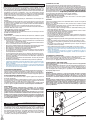
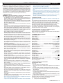
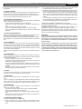
D811517 ver. 03 15/01/07
I
AUTOMAZIONI A PISTONE PER CANCELLI A BATTENTE
GB ELECTROMECHANICAL PISTON FOR SWING GATES
F VERIN ELECTROMECANIQUE POUR PORTAILS A VANTAUX
D ELEKTROM ECHANISCHER KOLBEN FÜR FLÜGELTORE
8
027908
298492
E PISTON ELECTROMECANICO PARA CANCELAS DE BATIENTE
P AUTOMATIZAÇÕES DE PISTÃO PARA PORTÕES DE BATENTE
PHOBOS N BT
ISTRUZIONI D’USO E DI INSTALLAZIONE
INSTALLATION AND USER’S MANUAL
INSTRUCTIONS D’UTILISATION ET D’INSTALLATION
INSTALLATIONS-UND GEBRAUCHSANLEITUNG
INSTRUCCIONES DE USO Y DE INSTALACION
INSTRUÇÕES DE USO E DE INSTALAÇÃO
Via Lago di Vico, 44
36015 Schio (VI)
Tel.naz. 0445 696511
Tel.int. +39 0445 696533
Fax 0445 696522
Internet: www.bft.it
E-mail: [email protected]
D811517_03
2 - PHOBOS N BT Ver. 03
D811517_03
ITALIANO
MANUALE D’USO
Nel ringraziarVi per la preferenza accordata a questo prodotto, la ditta è
certa che da esso otterrete le prestazioni necessarie al Vostro uso. Leggete attentamente l’opuscolo “Avvertenze” ed il “Libretto istruzioni” che
accompagnano questo prodotto in quanto forniscono importanti indicazioni
riguardanti la sicurezza, l’installazione, l’uso e la manutenzione. Questo
prodotto risponde alle norme riconosciute della tecnica e della disposizioni
relative alla sicurezza. Confermiamo che è conforme alle seguenti direttive
europee: 89/336/CEE, 73/23/CEE (e loro modifiche successive).
1) GENERALITÀ
Pistone elettromeccanico progettato per automatizzare cancelli di tipo residenziale.
Il motoriduttore mantiene il blocco in chiusura ed apertura senza necessità
di elettroserratura. L’attuatore è provvisto di limitatore di coppia elettronico. Deve essere comandato da un quadro comandi elettronico dotato di
regolazione di coppia.
Il funzionamento a fine corsa è regolato da due finecorsa magnetici.
L’attuatore è provvisto di un sistema di rilevamento ostacoli secondo le
normative EN12453 e EN 12445.
Sono disponibili i seguenti accessori opzionali:
- Kit batteria tampone mod. BT BAT
Consente il funzionamento dell’automazione anche se manca per un breve
periodo l’alimentazione di rete.
2) SICUREZZA
L’automazione, se installata ed utilizzata correttamente, soddisfa il grado
di sicurezza richiesto.
Tuttavia è opportuno osservare alcune regole di comportamento per evitare
inconvenienti accidentali.
• Prima di usare l’automazione, leggere attentamente le istruzioni d’uso
e conservarle per consultazioni future.
• Tenere bambini, persone e cose fuori dal raggio d’azione dell’automazione, in particolare durante il funzionamento.
• Non lasciare radiocomandi o altri dispositivi di comando alla portata dei
bambini onde evitare azionamenti involontari dell’automazione.
• Non contrastare volontariamente il movimento dell’anta.
• Non modificare i componenti dell’automazione.
• In caso di malfunzionamento, togliere l’alimentazione, attivare lo sblocco
di emergenza per consentire l’accesso e richiedere l’intervento di un
tecnico qualificato (installatore).
• Per ogni operazione di pulizia esterna, togliere l’alimentazione di rete.
• Tenere pulite le ottiche delle fotocellule ed i dispositivi di segnalazione
luminosa. Controllare che rami ed arbusti non disturbino i dispositivi di
sicurezza (fotocellule).
• Per qualsiasi intervento diretto all’automazione, avvalersi di personale
qualificato (installatore).
• Annualmente far controllare l’automazione da personale qualificato.
• L’attivazione dello sblocco manuale potrebbe causare movimenti incontrollati della porta in presenza di guasti meccanici oppure se la porta
non è in equilibrio.
• Esaminare frequentemente l’installazione se presenta sbilanciamenti o
segni di danni meccanici a” cavi e supporti”. Non utilizzare l’automatismo
se necessita di interventi di riparazione.
3) MANOVRA DI EMERGENZA
Ogni operatore è dotato di sblocco a chiave. Alzato il tappo copriserratura (fig.1),
inserire la chiave di sblocco in dotazione e ruotare di 90° in senso orario.
Spingere manualmente l’anta per aprire il cancello.Per ripristinare il funzionamento motorizzato, ruotare la chiave al contrario e rimettere il tappo di copertura.
4) MANUTENZIONE E DEMOLIZIONE
La manutenzione dell’impianto va fatta eseguire regolarmente da parte di
personale qualificato.
Se il cavo di alimentazione é danneggiato esso deve essere sostituito dal
costruttore o dal suo servizio assistenza tecnica o comunque da persona
con qualifica similare, in modo da prevenire ogni rischio.
I materiali costituenti l’apparecchiatura e il suo imballo vanno smaltiti secondo
le norme vigenti. Le pile non devono essere disperse nell’ambiente.
AVVERTENZE
Il buon funzionamento dell’operatore è garantito solo se vengono
rispettate i dati riportati in questo manuale. La ditta non risponde dei
danni causati dall’inosservanza delle norme di installazione e delle
indicazioni riportate in questo manuale.
Le descrizioni e le illustrazioni del presente manuale non sono impegnative. Lasciando inalterate le caratteristiche essenziali del prodotto,
la Ditta si riserva di apportare in qualunque momento le modifiche che
essa ritiene convenienti per migliorare tecnicamente, costruttivamente
e commercialmente il prodotto, senza impegnarsi ad aggiornare la
presente pubblicazione.
ENGLISH
1) GENERAL OUTLINE
Electromechanical piston designed to automate residential gates.
The gearmotor keeps the gate locked on closing and on opening, without needing an electric lock for leaves up to 3 m long. For leaves ranging between 3m
and 5m long, the electric lock becomes indispensable.The operator is provided
with an electronic torque limiter. It must be controlled by an electronic control
panel provided with torque setting. The end-of-stroke operation is controlled by
two magnetic limit devices.The
The operator is provided with an obstacle detection
system complying with EN12453 and EN 12445 standards.
The following optional accessories are available on request:
- Buffer battery kit mod. BT BAT
Allows operation of the automation even when there is no mains power
supply for a short period of time.
2) SAFETY
If correctly installed and used, this automation device satisfies the required
safety level standards.
However, it is advisable to observe some practical rules in order to avoid
accidental problems.
• Before using the automation device, carefully read the operation instructions and keep them for future reference.
• Keep children, people and things outside the automation working area,
particularly during its operation.
• Keep radio control or other control devices out of children’s reach, in order
to avoid any unintentional automation activation.
• Do not intentionally oppose the leaf movement.
• Do not modify the automation components.
• In case of malfunction, disconnect the power supply, activate the emergency
release to have access to the automation and request the assistance of
a qualified technician (installer).
• Before proceeding to any outside cleaning operation, disconnect the power
supply.
• Keep the photocell optical components and light signal devices clean.
• Check that the safety devices (photocells) are not obscured by branches
or shrubs.
• For any direct assistance to the automation system, request the help of
a qualified technician (installer).
• Have qualified personnel check the automation system once a year.
• Manual release activation could cause the door to be subject to uncontrolled
movements in the case where any mechanical faults are present or the
door is not balanced.
• Inspect the installation frequently if it shows any unbalance or signs of
mechanical damage to ”cables and supports”. Do not use the operator if
it needs to be repaired.
3) EMERGENCY MANOEUVRE
All controllers feature a key release mechanism. After lifting the lock cover
(fig.1), insert the release key supplied and turn it clockwise by 90°.
Push the leaf manually to open the gate. To reset the motorised operation,
turn the key in the opposite direction and refit the cover.
4) MAINTENANCE AND DEMOLITION
The maintenance of the system should only be carried out by qualified
personnel regularly.
If the power supply cable is damaged, it must be replaced by the manufacturer
or its technical assistance service, or else by a suitably qualified person, in
order to prevent any risk.The materials making up the set and its packing
must be disposed of according to the regulations in force.Batteries must
be properly disposed of.
WARNINGS
Correct controller operation is only ensured when the data contained
in the present manual are observed. The company is not to be held
responsible for any damage resulting from failure to observe the
installation standards and the instructions contained in the present
manual.
The descriptions and illustrations contained in the present manual are
not binding. The Company reserves the right to make any alterations
deemed appropriate for the technical, manufacturing and commercial
improvement of the product, while leaving the essential product features unchanged, at any time and without undertaking to update the
present publication.
Fig. 1
USER’S MANUAL
Thank you for buying this product, our company is sure that you will be more
than satisfied with the product’s performance. The product is supplied with
a “Warnings” leaflet and an “Instruction booklet”. These should both be
read carefully as they provide important information about safety, installation, operation and maintenance. This product complies with the recognised
technical standards and safety regulations. We declare that this product
is in conformity with the following European Directives: 89/336/EEC and
73/23/EEC (and subsequent amendments).
PHOBOS N BT Ver. 03 - 3
D811517_03
INSTALLATION MANUAL
Thank you for buying this product, our company is sure that you will
be more than satisfied with the product’s performance. The product is
supplied with a “Warnings” leaflet and an “Instruction booklet”. These
should both be read carefully as they provide important information about
safety, installation, operation and maintenance. This product complies with
the recognised technical standards and safety regulations. We declare
that this product is in conformity with the following European Directives:
89/336/EEC and 73/23/EEC (and subsequent amendments).
1) GENERAL SAFETY
WARNING! An incorrect installation or improper use of the product
can cause damage to persons, animals or things.
• The “Warnings” leaflet and “Instruction booklet” supplied with this
product should be read carefully as they provide important information
about safety, installation, use and maintenance.
• Scrap packing materials (plastic, cardboard, polystyrene etc) according
to the provisions set out by current standards. Keep nylon or polystyrene
bags out of children’s reach.
• Keep the instructions together with the technical brochure for future
reference.
• This product was exclusively designed and manufactured for the use
specified in the present documentation. Any other use not specified
in this documentation could damage the product and be dangerous.
• The Company declines all responsibility for any consequences resulting
from improper use of the product, or use which is different from that
expected and specified in the present documentation.
• Do not install the product in explosive atmosphere.
• The construction components of this product must comply with the
following European Directives: 89/336/CEE, 73/23/EEC, 98/37/EEC
and subsequent amendments. As for all non-EEC countries, the abovementioned standards as well as the current national standards should
be respected in order to achieve a good safety level.
• The Company declines all responsibility for any consequences resulting from failure to observe Good Technical Practice when constructing
closing structures (door, gates etc.), as well as from any deformation
which might occur during use.
• The installation must comply with the provisions set out by the following European Directives: 89/336/CEE, 73/23/EEC, 98/37/EEC and
subsequent amendments.
• Disconnect the electrical power supply before carrying out any work
on the installation. Also disconnect any buffer batteries, if fitted.
• Fit an omnipolar or magnetothermal switch on the mains power supply,
having a contact opening distance equal to or greater than 3,5 mm.
• Check that a differential switch with a 0.03A threshold is fitted just
before the power supply mains.
• Check that earthing is carried out correctly: connect all metal parts for
closure (doors, gates etc.) and all system components provided with
an earth terminal.
• Fit all the safety devices (photocells, electric edges etc.) which are
needed to protect the area from any danger caused by squashing,
conveying and shearing.
• Position at least one luminous signal indication device (blinker) where
it can be easily seen, and fix a Warning sign to the structure.
• The Company declines all responsibility with respect to the automation
safety and correct operation when other manufacturers’ components
are used.
• Only use original parts for any maintenance or repair operation.
• Do not modify the automation components, unless explicitly authorised
by the company.
• Instruct the product user about the control systems provided and the
manual opening operation in case of emergency.
• Do not allow persons or children to remain in the automation operation
area.
• Keep radio control or other control devices out of children’s reach, in
order to avoid unintentional automation activation.
• The user must avoid any attempt to carry out work or repair on the
automation system, and always request the assistance of qualified
personnel.
• Anything which is not expressly provided for in the present instructions,
is not allow.
• Installation must be carried out using the safety devices and controls
prescribed by the EN 12978 Standard.
• Check that the stated temperature range is compatible with the place
where the operator is to be installed.
• If present, the hold button (hold-to-run control) must be fitted within
•
•
•
ENGLISH
sight of the door but away from the moving parts, at a height of 1.5 m,
and must not be accessible to the public.
If the operator is fitted at a height lower than 2.5 m, you must guarantee
an adequate degree of protection for the electrical and mechanical
parts.
Make sure that squashing is avoided between the moving parts and
surrounding fixed parts. Fit all the safety devices (photocells, safety
edges etc.) required to protect the area from any danger of squashing,
drawing in and shearing.
After completing the installation, ensure that the motor is set correctly
and that the protection and release systems operate correctly.
2) GENERAL OUTLINE
Electromechanical operator designed to automate residential-type gates.
The gearmotor keeps the gate locked on closing and on opening, without
needing an electric lock for leaves up to 3 m long. For leaves ranging
between 3m and 5m long, the electric lock becomes indispensable.
The operator is provided with an electronic torque limiter. It must be controlled by an electronic control panel provided with torque setting.
The end-of-stroke operation is controlled by two magnetic limit devices.
The operator is provided with an obstacle detection system complying
with EN12453 and EN 12445 standards.
The following optional accessories are available on request:
- Buffer battery kit mod. PHOBOS-BT BAT
Allows operation of the automation even when there is no mains power
supply for a short period of time.
3) TECHNICAL SPECIFICATIONS
3.1) PHOBOS N BT
Power supply: .............................................................................. 24V
Motor revolutions: ....................................................................2500 min-1
Absorbed power:.............................................................................. 40 W
Absorbed current: ............................................................................1.5 A
Push and pull force: ..................................................... 2000 N (~200 kg)
Working stroke: ........................................................................... 295 mm
Stem speed:...................................................................20 mm/s approx.
Impact reaction: ...................... Torque limiter aboard Libra control board
Limit devices: .............................. Magnetic, incorporated and adjustable
Manual manoeuvre: ....................................................... CLS release key
No. of manoeuvres in 24hours: ....................................... 60 manoeuvres
Maximum leaf length:................................................................ 1800 mm
Max. leaf weight: .......................................................... 2500 N (~250 kg)
Environmental conditions:......................................from -20 °C to +50 °C
Protection level: .............................................................................. IP X4
Dimensions: ............................................................................... See fig.1
Controller weight:................................................................... 50N (~5kg)
Lubrication: ................................................................. permanent grease
3.2) BATTERY KIT BT BAT
Charging voltage:..................................................................... 27.2V
Charging current: ..........................................................................130mA
Outside temperature when values were measured: ........................ 25°C
Battery capacity: .............................................................. 2x (12V 1.2Ah)
Flat battery protection threshold: ............................................. 20.4V
Battery charging time:............................................................... 12/14 hrs
4) INSTALLATION OF THE ACTUATOR
4.1) Preliminary checks
Check that:
• The gate structure is sufficiently sturdy.
• Also make sure that the actuator pushes against the leaf reinforced
section.
• The leaves move manually and without effort all along their stroke.
• If the gate has not been recently installed, check the wear condition of
all components.
• Repair or replace faulty or worn parts.
The automation reliability and safety are directly influenced by the state
of the gate structure.
• Fit the magnet-holder “M” by inserting it into the front bracket “F” until
a click is heard (as from Fig.7).
The diagram in fig. 2 should be used as a reference for installation and
consult the table for the distances in mounting the gate post.
The diagram in fig. 2 uses the following legend:
P
Gate post rear fastening bracket
PHOBOS N BT Ver. 03 - 9
F
a-b
C
D
X
Z
kg
A°
INSTALLATION MANUAL
Front leaf fastening bracket
“P” bracket installation value
Distance between fixing points (C = 705 mm)
Gate length
Distance from gate axis to the edge of the post
Always over 45 mm (b - X)
max. weight of leaf
leaf opening in degrees
4.2) How to read the installation distance tables (Fig.2)
Select “a” and “b” according to the angle in degrees A° that the gate has to
open. The optimum “a” and “b” values for 92° opening at constant speed are
highlighted.
If there is too large a difference between “a” and “b”, the leaf will not travel
smoothly and the pushing or pulling force will fluctuate during its stroke.
To respect the opening speed and ensure the controller operates correctly,
it is best to keep the difference between “a” and “b” as low as possible.
The table has been worked out for a 20-mm thick medium-size gate.
Always check that there is no possible collision between the gate and
the operator.
4.3) Off-standard installations.
Fig. 3 shows an installation with a recess when there is not sufficient
space between the leaf and perimeter wall.
When the leaf position does not provide for a value of “b” present in the table,
change the length of the bracket or make a recess in the gate-post (Fig. 5).
4.4) Anchoring the attachments to the gate-post.
Fix the bracket “P” (fig. 6) to the gate-post with a good welding.
In the same way, weld the “F” bracket to the gate (or fix it with 4 M8 screws),
making sure that the operator to be fitted is positioned parallel with the gate
movement plane, fig.7. The bracket “F” should be welded in the same way
to the gate taking care that the actuator can then be mounted perfectly
horizontal to the line of travel of the gate fig. 7.
• If the gate-post is in brick, the plate “PF” must be set soundly into the post
using adequately sized cramps “Z” welded to the back of the plate (fig. 8).
• If the gate-port is in stone and the gate is small, the plate “PF” can be
mounted with four metal expansion plugs “T” (fig. 9). If a larger gate is
being installed it would be better to use a corner plate “PF” (fig. 10).
Fit the rear bracket pin as in Fig.6.
4.5) Anchoring the attachments to the gate leaf.
Fixing bracket “F” must be fixed at a distance of 705 mm from attachment
P in Fig.6.
IMPORTANT: the front bracket must be fitted with the bush collar
protruding UPWARDS (Fig.4 Ref.A).
4.6) Power supply cable (Fig.12)
The board power supply cable must be of the H 05 RN-F type or equivalent.
The equivalent cable must guarantee:
- permanent outside use
- rated voltage of 300/500 V
- maximum temperature on the cable surface of +50° C
- minimum temperature of -25° C
Moreover, it must have a minimum section of 3 x 1.5 mm2 and, for the
cable to hold correctly, it must be provided with an external sheath of Ø =
7.1 to 9.6 mm. Insert the cable into O ring “K” (Fig.12), strip it by about 40
mm and connect the cables to the terminal bar (see diagram S).
Position the cable sheath so that O ring “K” is inserted in its housing in
the base and, leaving the sheath protrude by about J=5 mm (as shown
in Fig.12), close the hatch and fix it by means of the 3 screws.
4.7) Operator fitting
Position the operator on the brackets and fix everything as indicated in
Fig. 6 and 7.
In the case of gates moving over a slope (opening towards the inside with
an upward sloping driveway), the operator allows the gate to oscillate with
respect to the horizontal axis, for the maximum values indicated in fig.7.
5) GROUND GATE STOPS
For the controller to operate correctly the gate stop “B” must be used both
in opening and closing, as shown in fig. 11.
6) THE ELECTRICAL PLANT SET-UP (fig. 13).
Lay out the electrical installation (fig. 13) with reference in force for electrical installation.
10 - PHOBOS N BT Ver. 03
The mains power supply connections must be kept totally separate from the
service connections (photocells, electric edges, control devices etc.).
Connect the control and safety devices in compliance with the previously
mentioned electrical installation standards.
Fig.13 shows the number of connections and the cross section for power
supply cables having a length of approximately 100 metres; in case of
longer cables, calculate the cross section for the true automation load.
When the auxiliary connections exceed 50-metre lengths or go through
critical disturbance areas, it is recommended to decouple the control and
safety devices by means of suitable relays.
The main automation components are (fig.13):
I
Type-approved omnipolar circuit breaker with at least 3,5 mm contact opening, provided with protection against overloads and short
circuits, suitable for cutting out automation from the mains. If not
already installed, place a type-approved differential switch with a
0.03A threshold in the circuit just before the automation system.
Qr
Control panel and incorporated receiver.
S
Key selector
AL Blinker tuned in with antenna
M
Controller
Fte Pair of outside photocells (transmitters)
Fre Pair of outside photocells (receivers)
Fti
Pair of inside photocells with column (transmitters)
Fri Pair of inside photocells with column (receivers)
T
1-2-4 channel transmitter
RG58 Antenna cable
The connection between the operator and the control panel should be
carried out using three cables, identified as follows:
Fig. 17 shows the wiring diagram of the LIBRA control unit.
Should the opening or closing direction be incorrect, it is possible to invert
the connections of motor + and motor - on the control board.
The first command after an interruption of the power supply should be
an opening manoeuvre.
All metal masses in the housings of equipment and automation must be
earthed.
7) ADJUSTING THE PUSHING FORCE
WARNING: Check that the impact force value measured at the
points established by the EN 12445 standard is lower than that
specified in the EN 12453 standard.
The pushing force is calibrated by means of the torque regulator in the
control unit. The optimum torque must allow a complete opening or closing
cycle with the minimum force necessary. An excessive torque can reduce
the anti-crush safety. In the other case, an insufficient torque can impede
the manoeuvres. Consult the control unit’s instruction manual.
8) LIMIT DEVICE ADJUSTMENT
End-of-stroke adjustment is carried out by correctly positioning the limit
devices (FC1 and FC2 in Fig. 1).
8.1) Closing limit device adjustment (Fig. 14):
Carry out a closing manoeuvre to check that limit device activation is
correct; if the leaf stops before the required closing position, slightly
move the limit device towards the head cap; if, on the contrary, the leaf
meets the ground closing stop and the operator starts to reverse, slightly
move the limit device towards the operator body. After completing the
adjustment, fix screw A.
ATTENTION! To avoid braking the limit switch cable, tighten screw A
keeping the wire B well tightened (as shown in Fig.14A).
8.2) Opening limit device adjustment (Fig. 15):
Carry out an opening manoeuvre to check the exact limit activation point;
if the leaf stops before the required opening point, slightly move the limit
device towards the operator body; if, on the contrary, the leaf reaches
the opening ground stop plate and the operator reverses its movement,
slightly move the limit device towards the rod end. After completing the
adjustment, fix screw A. Limit device activation takes place about 5 mm
between the magnetic limit device tip and the nut screw end.
N.B. When using the LIBRA control board, remember to slightly anticipate
the intervention of the limiting devices because the stem, after intercepting
the limiting devices, continues to move for a further 1-2 mm. (100 ms).
D811517_03
ENGLISH
D811517_03
INSTALLATION MANUAL
In this way a perfect strike of the leaves against the ground supports is
guaranteed.
9) MANUAL OPENING
All controllers feature a key release mechanism. After lifting the lock cover
(fig.16), insert the release key supplied and turn it clockwise by 90°.
Push the leaf manually to open the gate. To reset the motorised operation,
turn the key in the opposite direction and refit the cover.
10) CHECKING THE AUTOMATION
Before considering the automation completely operational, the following
checks must be made with great care:
• Check that all the components are firmly anchored.
• Control all the safeties work properly (i.e. photocells, pneumatic skirt,
etc.).
• Check the emergency manoeuvre control.
• Check the opening and closing manoeuvres using the controls.
• Check the control unit’s electronic logic in normal (or customised)
operation.
11) USE OF THE AUTOMATION
Since the automation may be remote controlled either by radio or a Start
button, it is essential that all safeties are checked frequently.
Any malfunction should be corrected immediately by a qualified specialist.
Keep children at a safe distance from the field of action of the automation.
12) THE CONTROLS
With the automation the gate has a power driven opening and closing.
The controls can come in various forms (i.e. manual, remote controlled,
limited access by magnetic badge, etc.) depending on needs and installation characteristics. For details on the various command systems, consult
the specific instruction booklets.
Anyone using the automation must be instructed in its operation and controls.
ENGLISH
b) If the moving direction of the leaf is opposite to the right one, invert
the motor running connections (motor +red/ motor - black).
c) Should the gate stop and hit the ground stopping device and the actuator reverse its moving direction, it means that the limiting devices have
not been adjusted correctly. If this happens on the opening stopping
device, move the opening limiting device towards the hinge of the
gate until the correct position is found(see adjustment of the limiting
devices).
If, on the contrary, this happens on the closing stopping device, move
the closing limiting device towards the stem plug until the correct position is found (see adjustment of the limiting devices).
17.2) Incorrect operation of the electrical accessories
All control and safety devices can cause, in case of failure, malfunctioning
or stoppage of the automation.
To identify the failure, it is advised to disconnect all the devices of the
automation one by one until the one causing the problem is found.
After fixing or replacing the defective device, reset all the devices previously disconnected. Refer to the relevant instruction manual for all the
devices installed on the automation.
WARNINGS
Correct controller operation is only ensured when the data contained
in the present manual are observed. The company is not to be held
responsible for any damage resulting from failure to observe
the installation standards and the instructions contained in the
present manual.
The descriptions and illustrations contained in the present manual
are not binding. The Company reserves the right to make any alterations deemed appropriate for the technical, manufacturing and
commercial improvement of the product, while leaving the essential
product features unchanged, at any time and without undertaking
to update the present publication.
13) MAINTENANCE
When carrying out maintenance operation on the controller, disconnect
it from the mains power supply. The actuator does not require periodical
maintenance operations.
• Check the safety devices of the gate and automation.
• Periodically check the pushing force and correct the value of the electric
torque in the control board if necessary.
• In case of unsolved operation failures, disconnect the unit from the
mains power supply and ask for the intervention of qualified personnel
(installer).
When the unit is out of order, activate the manual release to perform
manual opening and closing manoeuvres.
14) NOISE
The aerial noise produced by the gearmotor under normal operating
conditions is constant and does not exceed 70dB(A).
15) SCRAPPING
Materials must be disposed of in conformity with the current regulations.
In case of scrapping, the automation devices do not entail any particular
risks or danger. In case of recovered materials, these should be sorted
out by type (electrical components, copper, aluminium, plastic etc.).
16) DISMANTLING
When the automation system is disassembled to be reassembled on
another site, proceed as follows:
• Disconnect the power supply and the entire electrical installation.
• Remove the gearmotor from its fixing base.
• Disassemble the control panel, if separate, and all installation components.
• In the case where some of the components cannot be removed or are
damaged, they must be replaced.
17) TROUBLES AND SOLUTIONS
17.1) Incorrect operation of gearmotor
a) Check for the presence of power supply to the gearmotor using a
suitable instrument after opening or closing commands have been
given.
PHOBOS N BT Ver. 03 - 11
D811517_03
Fig. 1
102
825
Cu MAX 295 mm
68
55
80
Fig. 2
Z=b-x >45mm
D
b
x
F
a
P
kg
C=705 mm
a(mm)
b(mm)
100
110
120
130
140
150
160
170
180
190
200
210
100
90
84
79
110
98
90
85
84
77
120
104
97
91
86
82
78
130
110
102
96
91
87
83
79
140
150
160
170
180
120
114
107
101
96
92
88
84
81
109
105
100
96
92
89
85
82
104
100
97
92
89
85
99
96
93
90
96
93
Installazioni consigliate / Recommended installation
Installations conseillées / Empfohlene Installationen
Instalaciones aconsejadas / Instalações Aconselhadas
24 - PHOBOS N BT Ver. 03
D811517_03
Fig. 3
Fig. 4
A
65
b
a
Fig. 5
b
962 807
Fig. 6
Fig. 7
+ 4o
- 4o
F
P
M
B
S
PHOBOS N BT Ver. 03 - 25
Fig. 9
Fig. 10
T
Z
PF
PF
PF
Fig. 11
Fig. 12
B
3 x 1,5 mm2
Ø=7.1÷9.6
K
Destra/Right/Droite
Rechts/Derecha
Direita
Sinistra/Left/Gauche
Links/Izquierda
Esquerda
B
B
S
1
2 3
MOT MOT +
FC
J
K
Fig. 13
M
AL
S
2
m
2
mm
1
2x
,5m
M
1
3x
2
P
3x1m
m2
3x1
m
m
1m
4x
Fti
RG
Fte
CF
m2
58
2x1
,5
2
mm
1,5
3x
T
2
Fri
4x
m
1m
26 - PHOBOS N BT Ver. 03
R
Q
mm2
2x1
m 2
2x1 m
,5m 2
m
CF
D811517_03
Fig. 8
I
3x1
,5m
m2
D811517_03
Fig. 15
Fig. 14
FC2 (CLOSE)
FC1 (OPEN)
B
A
A
Fig. 17
Fig. 14A
L
230V~
1
JP1
N
2
+
3
M2
FC
A
+
M1
FC
B
4
5
6
JP9
7
8
9
40W max.
10
11
24V~
Fig. 16
12
13
24V~
VSafe
14
NO
COM
15
START
16
STOP
17
PHOT
18
FAULT
19
PED
20
NC
NC
LIBRA
NO
NO
JP8
21
22
ANT.
ANT
SHIELD
23 JP7
24
PHOBOS N BT Ver. 03 - 27