1
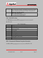
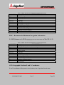
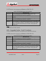
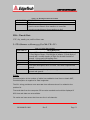
3100P PORTABLE
SUB-BOTTOM
TOPSIDE PROCESSOR
AND TOW FISH
USER’S HARDWARE MANUAL
Revision X / March 2010
Email: [email protected]
Web: http: //www.edgetech.com
4 Little Brook Rd.
West Wareham, MA 02576
Phone: 508-291-0057
Fax: 508-291-2491
FORWARD
This manual is intended to provide the user with an understanding of the operation and care
of the 3100P Portable Topside Processor. Although this manual covers the latest operational
features of the 3100P Portable Topside Processor, some features may be periodically
upgraded. Also, certain hardware may be changed per customer requirements. Therefore,
portions of this manual such as parts lists, and test features are subject to change. Such
sections should be used for reference only. When changes are made that affect system
operation, they will be explicitly noted. Also, some options and features may not be active in
your unit at time of delivery. Upgrades will be made available when these features are
implemented.
A 3100P System consists of two hardware components plus an installed software subcomponent. The hardware components are topside processor and the laptop computer with its
color video monitor and the EdgeTech 3100P Portable Topside Processor. Information
relating to the 3100P Portable Topside Processor is included in this manual. Information
relating to the laptop computer and instructions pertaining to the installed sonar processor
software are included in their own individual manuals.
EdgeTech has made every effort to document this product accurately and completely.
However, EdgeTech assumes no liability for errors or for any damages that result from use of
this manual or the equipment it accompanies. EdgeTech reserves the right to upgrade features
of this equipment and to make changes to this manual without notice at any time.
Since clear and concise documentation is inherent for proper operation and understanding of
the equipment, we solicit you to contact us with any questions or comments so that we may
enhance this manual.
EdgeTech
4 Little Brook Road
West Wareham, MA 02576
Tel: (508) 291-0057
Fax: (508) 291-2491
Email: [email protected]
WARNING
This equipment contains static sensitive devices that are extremely sensitive to static
electrical charges, which may be developed on the body and the clothing. Extreme care
should be taken when handling these devices both in and out of the circuit board. Normal
handling precautions involve the use of anti-static protection materials and grounding straps
for personnel.
This equipment generates, uses and can radiate radio frequency energy, and if not installed
properly may cause interference to radio communications.
It has not been tested to
compliance to the appropriate FCC rules designed to provide reasonable protection against
such interference when operated in a commercial environment. Operation of this equipment
in a residential area may cause interference, in which case the user, at his own expense, will
be required to take whatever measures needed to correct the interference. It is the user’s
responsibility to verify that the system complies with the applicable FCC emission limits.
High Voltage may be present in the towfish, power amplifier and the topside processor. Use
caution when the electronics are removed from their containers for servicing.
Operation with improper line voltage could cause serious damage to the equipment.
WARRANTY SATAMENT
All equipment manufactured by EdgeTech is warranted against defective components and
workmanship for a period of one year after shipment. Warranty repair will be done by
EdgeTech, free of charge. Shipping costs are to be borne by the customer. Malfunction due
to improper use is not covered in the warranty and EdgeTech disclaims any liability for
consequential damage resulting from defects in the performance of the equipment. No
product is warranted as being fit for a particular purpose and there is no warranty of
merchantability. This warranty applies only if:
I. The items are used solely under the operating conditions and in the manner
recommended in Seller’s instruction manual, specifications, or other literature.
II. The items have not been misused or abused in any manner or repairs attempted thereon.
III. Written notice of the failure within the warranty period is forwarded to Seller and the
directions received for properly identifying items returned under warranty are followed.
IV. The return notice authorizes Seller to examine and disassemble returned products to the
extent Seller deems necessary to ascertain the cause for failure.
The warranties expressed herein are exclusive.
There are no other warranties, either
expressed or implied, beyond those set forth herein, and Seller does not assume any other
obligation or liability in connection with the sale or use of said products. Any product or
service repaired under this warranty shall be warranted for the remaining portion of the
original warranty period only.
Equipment not manufactured by EdgeTech is supported only to the extent of the original
manufacturer’s warranties. Note: 90 day warranty applies to third-party items.
HARDWARE VARIATIONS & COMPATIBLITY
The 3100P Portable Topside Processor contains both standard PC and proprietary hardware.
At times EdgeTech may change these standard components due to their availability or
performance improvements. Although manufacturers, their models, and styles may change
from unit to unit, replacement components will generally be interchangeable. EdgeTech will
make all effort to see that replacement boards are interchangeable and use the same software
drivers. At times though, there may be instances where direct replacements do not exist.
When this happens, EdgeTech will provide the necessary drivers with the replacement part.
To our customers:
Thank you for purchasing one of our products. At EdgeTech, it is our policy to provide high
quality, cost-effective products and support services that meet or exceed your requirements,
to deliver them on time and to continuously look for ways to improve. We all take pride in
the products we manufacture.
We want you to be entirely satisfied with your equipment. The information in this manual
will get you started. It tells you what you need to get your equipment up and running, and
introduces its many features.
We always enjoy hearing from people who use our products. Your experience with our
products is an invaluable source of information that we can use to continuously improve what
we manufacture. We encourage you to contact or visit us to discuss any issues whatsoever
that relate to our products or your application.
The Employees of EdgeTech
TABLE OF CONTENTS
1.
Introduction...............................................................................................13
2.
Overview ....................................................................................................14
2.1. Product Specifications...........................................................................14
2.1.1. Supplied Components ....................................................................14
2.1.2. Physicals .........................................................................................14
2.1.3. Environment ...................................................................................15
2.1.4. Power requirements ........................................................................15
2.2. Tow Vehicle Interface ...........................................................................15
2.2.1. 3100P Topside/Notebook Computer Interfaces .............................15
2.2.2. Laptop Specifications:....................................................................15
2.2.3. Supplied Components: ...................................................................16
3.
3100P Portable Topside Unit Case ..........................................................17
3.1. Embedded Microprocessor ...................................................................18
3.2. Sonar Interface Board (Tiger Boards) ...................................................19
3.2.1. SB Carrier Board ............................................................................19
3.2.2. Sub-Bottom Acquisition Board ......................................................20
3.2.3. Sonar/IDE Interface Board.............................................................21
3.3. Ethernet Switch .....................................................................................22
3.4. Ethernet Wireless Bridge ......................................................................22
3.5. Power Amplifier ....................................................................................23
3.6. Power Board ..........................................................................................23
4.
Notebook Computer .................................................................................24
4.1. Navigation Interface ..............................................................................24
4.2. Serial Port Parameters ...........................................................................24
4.3. NMEA Approved Sentence Structure ...................................................25
4.3.1. Inputs ..............................................................................................26
4.4. Printer Connection ................................................................................34
4.4.1. EPC model GSP-1086 ....................................................................34
5.
Tow Cables.................................................................................................36
5.1. Tow Cable Characteristics ....................................................................36
5.2. AC power Cable ....................................................................................36
5.2.1. DC Power & Ethernet Cable ..........................................................37
5.2.2. Standard 35 Meter Towcable..........................................................37
5.2.3. Tow Vehicles ..................................................................................38
6.
System Installation and Connections ......................................................44
6.1. System Installation ................................................................................44
6.2. LED Diagnostics ...................................................................................45
6.2.1. RED LED = Power.........................................................................45
6.2.2. GREEN LED = System Ready ......................................................45
6.2.3. YELLOW LED = Ping...................................................................45
6.2.4. Troubleshooting..............................................................................46
6.3. Ethernet Connections ............................................................................46
6.3.1. Ethernet LAN Connection .............................................................46
6.3.2. Troubleshooting..............................................................................47
6.3.3. Wireless Networking Connection ..................................................47
7.
EdgeTech 3100P Network Configuration ...............................................48
7.1. Wireless Network Adapter TCP/IP Address: ........................................49
7.1.1. Wireless Networking ......................................................................49
7.1.2. 3100P Topside ................................................................................49
7.1.3. DESCRIPTION COMPONENT IP ADDRESS CAPABILITY ....50
8.
Internal Hardware ....................................................................................51
9.
3100P Topside Processor Parts List ........................................................54
10. 3100P Topside Processor Cables ..............................................................55
11. Contact and Service Information ............................................................58
12. Returned Material Authorization ...........................................................59
APPENDICES
APPENDIX A – WIRELESS SETUP………………………………………………….A-1
TABLE OF FIGURES
FIGURE 3-1 3100P PORTABLE TOPSIDE UNIT FUNCTIONAL BLOCK DIAGRAM ....................... 18
FIGURE 3-2 SB CARRIER BOARD ......................................................................................................... 20
FIGURE 3-3 SUB-BOTTOM ACQUISITION BOARD ............................................................................ 21
FIGURE 3-4 SONAR/IDE INTERFACE BOARD .................................................................................... 22
FIGURE 4-1 DISCOVER NAVIGATION INPUT SETUP WIZARD........................................................ 24
FIGURE 5-1 AC POWER CABLE ............................................................................................................. 37
FIGURE 6-1 3100P PORTABLE PROCESSOR CASE INTERFACE ....................................................... 44
FIGURE 7-1 3100P NETWORK CONFIGURATION DIAGRAM ........................................................... 48
FIGURE 7-2 WIRELESS TCP/IP ADDRESS ............................................................................................ 49
FIGURE 8-1 3100P CHASSIS ASSEMBLY DRAWING .......................................................................... 52
FIGURE 10-1 AC POWER CABLE ........................................................................................................... 55
FIGURE 10-2 TOW CABLE ...................................................................................................................... 56
FIGURE 10-3 DC POWER& ETHERNET CABLE ................................................................................... 57
TABLE OF TABLES
TABLE 2-1 LAPTOP SPECIFICATIONS ................................................................................................. 15
TABLE 4-1 SERIAL PORT CONFIGURATION SETTINGS .................................................................. 25
TABLE 4-2 NMEA APPROVED SENTENCE STRUCTURE .................................................................. 26
TABLE 4-3 GLL- GEOGRAPHIC POSITION-LATITUDE/LONGITUDE .............................................. 26
TABLE 4-4 TRANSIT FIX DATA.............................................................................................................. 27
TABLE 4-5 RMA RECOMMENDED MINIMUM NAVIGATION INFORMATION .............................. 28
TABLE 4-6 RMC RECOMMENDED MINIMUM NAVIGATION INFORMATION .............................. 28
TABLE 4-7 GXY-GEOGRAPHIC POSITION X AND Y COORDINATES ............................................. 29
TABLE 4-8 GGU-GEOGRAPHIC POSITION X AND Y COORDINATES ............................................. 29
TABLE 4-9 VTG-TRACK MADE GOOD AND GROUND SPEED ........................................................ 30
TABLE 4-10 DEPTH BELOW TRANSDUCER ....................................................................................... 30
TABLE 4-11 HEADING-DEVIATION & VARIATION .......................................................................... 31
TABLE 4-13 ZDA-TIME AND DATE ...................................................................................................... 31
TABLE 4-14 EVENT AND ANNOTATION ............................................................................................. 32
TABLE 4-15 EVENT, SET MARK AND ANNOTATION ........................................................................ 32
3100P-TOPSIDE PROCESSOR
TABLE 4-16 ETHERNET PRINTERS....................................................................................................... 34
TABLE 4-17 EPC 1086 SPECS .................................................................................................................. 34
TABLE 4-18 EPC 1086 SETTINGS ........................................................................................................... 35
TABLE 5-1 TOW VEHICLES SPECIFICATIONS ................................................................................... 38
990-0000058-1000
Rev F
Page 12
3100P-TOPSIDE PROCESSOR
1.
Introduction
The 3100P Portable Topside Processor provides an interface between a laptop computer
running EdgeTech's DISCOVER 3100P Sub-bottom Sonar acquisition software, and a
model SB-424 or SB-216S towfish. The end user need only supply a source of GPS data
and either AC or DC power to complete the acquisition package. The complete system
with the 3100P and towfish is the Model 3100P Sub-bottom Sonar System.
The 3100P unit is a self contained, portable unit with all interface and power supply
electronics housed within a rugged, waterproof (when the lid is closed) Storm ® case.
There is space inside the closed unit to accommodate an EdgeTech supplied laptop
personal computer.
The data and control interface between the laptop and the 3100P is via TCP/IP protocols
and may be via wireless or direct cable connections.
Edgetech recommends operating the portable with the cover open and laptop not sitting
on the faceplate. In extreme heat conditions a fan is suggested to move air across the
faceplate.
990-0000058-1000
Rev F
Page 13
3100P-TOPSIDE PROCESSOR
2.
Overview
The “portable” deck unit is splash proof and constructed of high-impact structural
polypropylene material. The deck unit provides the interface and acquisition hardware to
the tow fish. The firmware inside the deck unit interfaces to the notebook computer via
TCP/IP based Ethernet or wireless connection. While communication with the deck unit
the laptop computer is running DISCOVER acquisition software displaying and
recording data.
2.1.
Product Specifications
2.1.1.
Supplied Components
• Notebook Computer (No laptop optional)
• Discover 3100 Software
• 3100P Portable Processor case with integral interface and electronics components
• AC Power cable
• DC Power & Ethernet cable
• Spares Kit
• Manuals
2.1.2.
Physicals
Size : 390 D x 490 W x 190 H (mm), 15.2 D x 19.2 W x 7.3 H (inches)
Weight : 14.5 kg (31.8 lbs) with Notebook (Sony VAIO), 11.6 kg (25.5 lbs) without
Notebook
Construction : High-impact structural polypropylene
Color : Yellow
Sealing : Watertight cover O-ring seal with purge valve
990-0000058-1000
Rev F
Page 14
3100P-TOPSIDE PROCESSOR
2.1.3.
Environment
Open Cover Operating Temperature: 0°C to 40°C (32°F to 104°F) (shade conditions)
Storage Temperature : -20°C to 60°C (-4°F to 140°F)
Relative Humidity : Operating 0 to 80% (non-condensing), Non-operating 0 to 100%
2.1.4.
Power requirements
DC Input : 12 to 15 VDC
AC Input : 120/240 VAC (Auto-ranging)
CONDITIONS WATTS DC AMPS AC AMPS
Peak power (on startup) 300 Watts 20 Amps at 12 VDC 2 Amps at 120 VAC
Average operating power 48 Watts 4 Amps at 12 VDC 0.4 Amps at 120 VAC
2.2.
Tow Vehicle Interface
Tow Vehicle Power : 12V
Transmit/Receive Signals : Analog
Tow Cable: 35 meter Kevlar tow cable standard. 75 meter maximum length.
2.2.1.
3100P Topside/Notebook Computer Interfaces
Ethernet LAN : 100BaseT, TCP/IP
Wireless Ethernet : 802.11b/g
2.2.2.
Laptop Specifications:
Due to continuous product evolution in this area a firm specification cannot be provided.
The nominal specification for the EdgeTech supplied in the following table.
Table 2-1 Laptop Specifications
Laptop Specifications
Notebook computer
990-0000058-1000
Description
Sony Vaio-FS540P, or equivalent
Rev F
Page 15
3100P-TOPSIDE PROCESSOR
Operating System
Processor
Memory
Hard drive
Screen size
Wireless
2.2.3.
Windows XP Professional
Pentium M 730, 1.6 GHz
512 Mbytes
80 GBytes
15.4” - 1280 x 800 typical
Intel® Centrino™ or comparable
Supplied Components:
1. 3100P Portable Processor case with integral interface electronics
2. Laptop processor with DISCOVER 3100 Sub-bottom sonar software
3. AC power cable
4. DC Power & Ethernet cable
5. Spares Kit
6. Manuals
990-0000058-1000
Rev F
Page 16
3100P-TOPSIDE PROCESSOR
3.
3100P Portable Topside Unit Case
The portable topside unit case supplied is based on the Hardigg “Storm Case" and
provides a waterproof enclosure for the sonar and interface electronics, and Tow Vehicle
power supply. Power, Tow Vehicle cable and Ethernet cable connectors are mounted on a
recessed, waterproof panel, with LED indicators and ON/OFF switch. A functional block
diagram of the components contain within portable topside unit case is shown in Figure
3-1 3100P Portable Topside Unit Functional Block Diagram.
For an assembly drawing of the portable topside unit case refer to the Internal Hardware
Section of this manual.
990-0000058-1000
Rev F
Page 17
3100P-TOPSIDE PROCESSOR
Figure 3-1 3100P Portable Topside Unit Functional Block Diagram
3.1.
Embedded Microprocessor
The embedded processor is a high speed and low power industrial computer running
Windows XP Embedded as the operating system. Edgetech SONAR.EXE application
commands and controls the transmit and acquisition hardware while interface with the
laptop running DISCOVER sub-bottom sonar software. The operating system &
990-0000058-1000
Rev F
Page 18
3100P-TOPSIDE PROCESSOR
application are stored in 512MB of compact FLASH memory. The IDE interface
provides the data path between the processor & Sonar Interface Board (SIB).
3.2.
Sonar Interface Board (Tiger Boards)
The Sonar Interface Board Set (SIB) is the real-time controller for sonar processing. It
includes transmit waveform tables and multiple channels of 10-bit high speed D/A
converters, support for external and internal triggers, and support for multiple sonar ADC
converters. It was designed to support a combined sonar system (with both sub-bottom
as well as multi-frequency side-scan capability), or to be used single channel as a basic
sub-bottom controller. At periodic intervals it generates the transmit waveform(s), and it
continuously buffers ADC data.
These sonar interface boards represent a new generation of reengineered and optimized
sonar electronics. This tiger board set is designed to address a broad spectrum of sonar
applications from a common and well tested base of components. Among the features of
this generation are lower power consumption, higher speeds, smaller form factors, and
high analog sensitivity / minimum noise electronics for improved operating ranges.
The sonar interface board is actually comprised of a three board set of cards. The three
board set is made up of SB Carrier Board, Sub-Bottom Acquisition Board, and
Sonar/IDE Interface Board.
3.2.1.
SB Carrier Board
This board has the same physically size as an industry standard full slot PCI card. There
are two BNC connectors (J1-Triger-In & J3-Triger-Out) and female connectors on either
side for mating with the other two boards in the card set. An on board DC-DC converter
provides the +12 volts to the preamp in the tow fish.
990-0000058-1000
Rev F
Page 19
3100P-TOPSIDE PROCESSOR
Figure 3-2 SB Carrier Board
3.2.2.
Sub-Bottom Acquisition Board
The sub-bottom acquisition board contains band pass filtering and up to eight 24-bit
Analog-to-Digital Converters (ADC), only two channels are used for sub-bottom tow
fish. The first ADC channel is for received acoustic data from the preamp and the second
channel is used for power-up diagnostics.
990-0000058-1000
Rev F
Page 20
3100P-TOPSIDE PROCESSOR
Figure 3-3 Sub-Bottom Acquisition Board
3.2.3.
Sonar/IDE Interface Board
The sonar/IDE interface board is comprised of two RAM memory banks Acquisition
memory and chirp memory and six 10-bit DAC for generating transmit waveforms.
Transmit ping rate and sampling clock are generated from this board. The IDE portion of
the board provides the interfacing circuitry required to communicate between the
embedded processor and the SIB board set.
990-0000058-1000
Rev F
Page 21
3100P-TOPSIDE PROCESSOR
Figure 3-4 Sonar/IDE Interface Board
3.3.
Ethernet Switch
The Ethernet switch is a four port 10/100 Mbps TCP/IP used to create a local area
network interconnecting the deck unit embedded microprocessor, wireless bridge and the
topside laptop PC.
3.4.
Ethernet Wireless Bridge
Ethernet wireless bridge is provided to connect the embedded CPU with the topside
laptop PC. The wireless bride is set to IP address 192.9.0.255.
990-0000058-1000
Rev F
Page 22
3100P-TOPSIDE PROCESSOR
3.5.
Power Amplifier
The power amplifier receives the analog transmit signal from the sonar/IDE interface
board. The transmit signal is then amplified by a step-up transformers and 3-Stage “HBridge Amplifier Circuit”. The analog transmit signal is sent down the tow cable to the
tow fish.
3.6.
Power Board
The power board generates the assorted voltages required by the subassemblies inside the
topside unit. The assorted voltages are derived from input power which can be +12 VDC,
120VAC or 240VAC.
990-0000058-1000
Rev F
Page 23
3100P-TOPSIDE PROCESSOR
4.
Notebook Computer
The Notebook Computer runs the Discover 3100 Software. This provides for control,
storage and display of the Tow Vehicle data. The data is presented on a gray scale
waterfall display and is stored in SEGY format on hard disk. A user supplied GPS with
NMEA interface strings is required for positioning data.
See: http://www.edgetech.com/topsidelevel3discover.html
4.1.
Navigation Interface
The following information describes the serial port interface parameters for acquiring
navigation strings from a connected GPS unit or integrated navigation computer to the
serial port. Edgetech supplies a USB to serial cable for acquiring navigation data.
4.2.
Serial Port Parameters
The serial navigational com port is configured using the Discover Setup.
Figure 4-1 Discover Navigation Input Setup Wizard
990-0000058-1000
Rev F
Page 24
3100P-TOPSIDE PROCESSOR
Table 4-1 Serial Port Configuration Settings
Interface
USB to RS-232
Com Port
4
Baud Rate
4800
Data Bits
8
Start Bits
1
Stop Bits
1
Parity
None
Handshaking
None
Several of the messages conform to the NMEA 0183 protocol. For additional
information refer to:
NATIONAL MARINE ELECTRONICS ASSOCIATION
NMEA 0183
STANDARD FOR INTERFACING MARINE ELECTRONICS NAVIGATIONAL
DEVICES
Version 2.00
January 1, 1992
4.3.
NMEA Approved Sentence Structure
The following provides a summary explanation of the approved sentence structure:
$aabbb,c---c*hh<CR><LF>
990-0000058-1000
Rev F
Page 25
3100P-TOPSIDE PROCESSOR
Table 4-2 NMEA Approved Sentence Structure
ASCII
“$”
aa
HEX
24
bbb
“,”
2C
c---c
“*”
hh
<CR><LF>
4.3.1.
2A
0D 0A
DESCRIPTION
Start of Sentence
Dummy characters to start the Address Field (e.g. GP), not
used by EdgeTech products.
Sentence Formatter. Mnemonic code identifying the data
type and the string format of the successive fields.
Field Delimiter. Starts each field except Address and
Checksum fields. If it is followed by a null field, it is all
that remains to indicate no data in the field.
Data Sentence Block. Data field(s) preceded and separated
by delimiters.
Optional Checksum Delimiter.
Optional Checksum Field
Terminates Sentence
Inputs
The following are the approved NMEA sentences recommended for use with the
DISCOVER based systems.
GLL – Geographic Position – Latitude/Longitude
Latitude and Longitude of the present vessel position, time of position fix and status.$--
GLL,xxxx.xxx,a,yyyyyy.yyy,b,hhmmss.ss,A*hh<CR><LF>
Table 4-3 GLL- Geographic Position-Latitude/Longitude
ARGUMENT
xxxx.xxx
a
yyyyy.yyy
b
DESCRIPTION
Degrees|Minutes.decimal - 2 fixed digits of degrees, 2 fixed digits of
minutes and a variable number of digits for decimal fractions of minutes.
Leading zeros always included for degrees and minutes to maintain fixed
length.
N for North Latitude or S for South Latitude
Degrees|Minutes.decimal - 3 fixed digits of degrees, 2 fixed digits of
minutes and a variable number of digits for decimal fractions of minutes.
Leading zeros always included for degrees and minutes to maintain fixed
length.
E for East Longitude or W for West Longitude
990-0000058-1000
Rev F
Page 26
3100P-TOPSIDE PROCESSOR
hhmmss.ss
A
Time of position fix. Hours|Minutes|Seconds.decimal - 2 fixed digits of
hours, 2 fixed digits of minutes, 2 fixed digits of seconds and a variable
number of digits for decimal fractions of seconds. Always pad with
leading zeros. This field is optional
Status. Single character field:
A = Yes, Data Valid, Warning Flag Clear
V = No, Data Invalid, Warning Flag Set
TRF - TRANSIT Fix Data
$--TRF,hhmmss.ss,xxxxxx,llll.ll,a,yyyyy.yy,a,x.x,x.x,x.x,x.x,xxx,A*
hh <CR><LF>
Table 4-4 Transit Fix Data
ARGUMENT
hhmmss.ss
xxxxxx
llll.ll
a
yyyyy.yy
a
x.x
x.x
x.x
x.x
x.x
xxx
DESCRIPTION
UTC Time
Date, ddmmyy
LatitudeLeading zeros always included for degrees and minutes to
maintain fixed length.
North or South
Longitude
East or West
Elevation Angle
Number of iterations
Number of Doppler intervals
Update distance, nautical miles
Satellite ID
Data Validity
RMA - Recommended Minimum Navigation Information
$--RMA,A,llll.ll,a,yyyyy.yy,a,x.x,x.x,x.x,x.x,x.x,a*hh<CR><LF>
990-0000058-1000
Rev F
Page 27
3100P-TOPSIDE PROCESSOR
Table 4-5 RMA Recommended Minimum Navigation Information
ARGUMENT
A
llll.ll
a
yyyyy.yy
a
x.x
x.x
x.x
x.x
x.x
a
DESCRIPTION
Blink Warning
Latitude
North or South
Longitude
East or West
Time Difference A, uS
Time Difference B, uS
Speed Over Ground, Knots
Track Made Good, degrees true
Magnetic Variation, degrees
East or West
RMC - Recommended Minimum Navigation Information
$--RMC,hhmmss.ss,A,llll.ll,a,yyyyy.yy,a,x.x,x.x,xxxx,x.x,a*hh<CR><LF>
Table 4-6 RMC Recommended Minimum Navigation Information
ARGUMENT
hhmmss.ss
A
llll.ll
a
yyyyy.yy
a
x.x
x.x
xxxx
x.x
a
DESCRIPTION
UTC Time
Status, V = Navigation receiver warning
Latitude
North or South
Longitude
East or West
Speed over ground, knots
Track made good, degrees true
Date, ddmmyy
Magnetic Variation, degrees
East or West
GXY-Geographic Position-X and Y Coordinates
X and Y coordinates of the present vessel position, time of position fix and status.
990-0000058-1000
Rev F
Page 28
3100P-TOPSIDE PROCESSOR
$--GXY,xxxxxx.xxx,a,yyyyyy.yyy,b,hhmmss.ss,*hh<CR><LF>
Table 4-7 GXY-Geographic Position X and Y Coordinates
ARGUMENT
xxxxxx.xxx
a
yyyyyy.yyy
b
hhmmss.ss
DESCRIPTION
Double floating point numeric, may have leading negative sign.
Represents horizontal axis of plane (X coordinate)
Character label for X ( Must be valid ASCII character, but value is
ignored)
Double floating point numeric, may have leading negative sign.
Represents horizontal axis of plane (Y coordinate)
Character label for Y ( Must be valid ascii character, but value is ignored)
Time of position fix. Hours|Minutes|Seconds.decimal - 2 fixed digits of
hours, 2 fixed digits of minutes, 2 fixed digits of seconds and a variable
number of digits for decimal fractions of seconds. Always pad with
leading zeros.
NOTE:
The hhmmss.ss field is optional.
GGU - Geographic Position - X and Y Coordinates
X and Y coordinates of the present vessel position, time of position fix and status.
$--GGU,xxxxxxxx.x,a,yyyyyyyy.y,b,hhmmss.ss,*hh<CR><LF>
Table 4-8 GGU-Geographic Position X and Y Coordinates
ARGUMENT
xxxxxx.xxx
a
yyyyyy.yyy
b
hhmmss.ss
DESCRIPTION
Double floating point numeric, may have leading negative sign.
Represents horizontal axis of plane (X coordinate)
Character label for X ( Must be valid ASCII character, but value is
ignored)
Double floating point numeric, may have leading negative sign.
Represents horizontal axis of plane (Y coordinate)
Character label for Y ( Must be valid ascii character, but value is ignored)
Time of position fix. Hours|Minutes|Seconds.decimal - 2 fixed digits of
hours, 2 fixed digits of minutes, 2 fixed digits of seconds and a variable
number of digits for decimal fractions of seconds. Always pad with
leading zeros.
990-0000058-1000
Rev F
Page 29
3100P-TOPSIDE PROCESSOR
NOTE:
The hhmmss.ss field is optional.
VTG – Track Made Good and Ground Speed
The actual track made good and speed relative to the ground
$--VTG,x.x,T,x.x,M,x.x,N,x.x,K*hh<CR><LF>
Table 4-9 VTG-Track Made Good and Ground Speed
ARGUMENT
x.x
T
M
N
K
DESCRIPTION
Floating point numeric
Degrees True
Degrees Magnetic
knots
Kilometer/hour
NOTE:
Magnetic heading corrected for local deviation and Easterly/Westerly variation
would provide more accurate True vessel heading in degrees.
DBT – Depth Below Transducer
$--DBT,x.x,f,x.x,M,x.x,F*hh<CR><LF>
Table 4-10 Depth Below Transducer
ARGUMENT
x.x
f
M
F
DESCRIPTION
Floating point numeric
f = feet
M = meters
F = Fathoms
DPT - Heading - Deviation & Variation
$--DPT,x.x,x.x*hh<CR><LF>
990-0000058-1000
Rev F
Page 30
3100P-TOPSIDE PROCESSOR
Table 4-11 Heading-Deviation & Variation
ARGUMENT
x.x
x.x
DESCRIPTION
Depth, meters
Offset from transducer,
- positive means distance from tansducer to water line
- negative means distance from transducer to keel
ZDA - Time & Date
UTC, day, month, year, and local time zone
$--ZDA,hhmmss.ss,dd.mm,yyyy,ll,zz*hh<CR><LF>
Table 4-12 ZDA-Time and Date
ARGUMENT
hhmmss.ss
dd.mm
yyyy
ll
zz
DESCRIPTION
Universal Time Coordinated (UTC). Hours|Minutes|Seconds.decimal
- 2 fixed digits of hours, 2 fixed digits of minutes, 2 fixed digits of
seconds and a variable number of digits for decimal fractions of
seconds. Always pad with leading zeros.
Day(01 to 31)|.Month(01 to 12)
Year
Local zone description, 00 to ±13 hour. This field is optional and
ignored.
Local zone minutes description, same sign as local hours This field is
optional and ignored.
NOTES:
Zone description is the number of whole hours added to local time to obtain GMT,
Zone description is negative for East longitudes.
The GLL string provides a more accurate time reference since it is related to the
position fix.
Time and date from the computer CPU are also recorded and could be displayed if
GPS time and date are not available.
Fix marks are bars across the time zero line in all channels.
990-0000058-1000
Rev F
Page 31
3100P-TOPSIDE PROCESSOR
EVT - Event & Annotation (EdgeTech custom)
Event mark and related annotation provided by an integrated navigation system
$EGEVT,S,<Message>,<Message>,<Message>,...*hh<CR><LF>
Table 4-13 Event and Annotation
ARGUMENT
S
Message
DESCRIPTION
ASCII character status flag.
M = Print and Store event mark
Event annotation or just annotation message up to 80
characters long with a maximum number of messages being 10
NOTES:
Only the first 23 characters of the first message is saved in the SEG-Y data.
A maximum of 10 <Messages> separated by commas may be sent.
Annotation and event marks are placed on the screen when received, printed on
the printer if on, and stored on disk along with time, date and coordinates.
Event marks are displayed on the top of the screen as a tick mark and mark number.
Event mark number and annotation provided by an integrated navigation system.
EMA - Event, Set Mark, and Annotation (EdgeTech custom)
Event mark number and annotation provided by an integrated navigation system
$ETEMA,NNNNNN, <Message>,**hh<CR><LF>
Table 4-14 Event, Set Mark and Annotation
ARGUMENT
NNNNNN
Message
DESCRIPTION
Mark number to use for this event.
Event annotation message up to 23 characters long.
990-0000058-1000
Rev F
Page 32
3100P-TOPSIDE PROCESSOR
NOTES:
This message should only be used if it is imperative that the event mark
number be externally controlled, otherwise the $EGEVT message should be
used. If the mark number sent is the same as the current mark number the
message will be ignored.
A shortcut to the Windows HyperTerminal application is provided to check the
navigation input.
You must quit the application before running, and may
need to modify the properties if not running at 4800 baud. A sample display
is shown below.
$GPGLL,2600.0100,N,800000.0000,W,151228.99,A*67
$GPVTG,315.65,T,314.15,M,3.8,N,7.0,K*48
$GPZDA,151229.25,28.08,1997,06,00*45
$EGEVT,M,EventNo,Time,Position,Annotation,*73
$GPGLL,2600.0125,N,8000.0025,W,151229.50,A*84
$GPVTG,316.65,T,315.15,M,3.9,N,7.1,K*33
$GPZDA,151229.75,28.08,1997,06,00*45
$EGEVT,M,EventNo,Time,Position,Annotation,*48
$GPGLL,2600.0150,N,800000.0050,W,151229.99,A*12
$GPVTG,315.85,T,314.65,M,3.8,N,7.0,K*58
$GPZDA,151230.25,28.08,1997,06,00*72
$EGEVT,M,EventNo,Time,Position,Annotation,*48
NOTES:
The number of incoming strings should be limited to the five mentioned
above.
For accurate fixes, the navigation strings should be updated once a second
or faster.
990-0000058-1000
Rev F
Page 33
3100P-TOPSIDE PROCESSOR
4.4.
Printer Connection
Note: Printing is not supported at this time on the 3100P portable topside.
The information contained in section 4 is for future reference.
Various types of ETHERNET thermal continuous printers may be interfaced in the
future. To install a supported model, connect the printer cable to the parallel port. A
PCMCIA parallel port card is provided to interface to the printers in the following table:
Table 4-15 ETHERNET Printers
Printers
iSys V8.5-ETHERNET
EPC 1086-NT
4.4.1.
EPC model GSP-1086
The EPC model GSP-1086-NT is a widely used gray scale continuous printer in the
marine industry. It provides high quality images on a ten inch thermal printhead. The
software defined control panel makes the printer configurable to a wide range of
applications.
Table 4-16 EPC 1086 Specs
Paper
Thermal or plastic
Data point
2048
Paper roll length
Film Length
Paper/Film Width
Resolution
Tone Shades
Interface
Plot Speed
150ft(4507m)
130ft (39.6m)
10.48in (26.6cm)
203 dots per inch (8 dots/mm)
Up to 256 gray scales
Parallel
43 ms@ 64 shades
990-0000058-1000
Rev F
Page 34
3100P-TOPSIDE PROCESSOR
The following are the required settings on the printer for proper interface with the 3100P
system.
Table 4-17 EPC 1086 Settings
Trigger
Internal
Data Input
Parallel
Sweep
Forward
LPI
200
Width
2048
Data Type
6 bits
Shades
64
Image
Positive
Contrast
40%
990-0000058-1000
Rev F
Page 35
3100P-TOPSIDE PROCESSOR
5.
5.1.
Tow Cables
Tow Cable Characteristics
The physical and electrical characteristics contained in this document are believed to be
reliable and are derived from vendor-supplied data based upon industry standards.
¾ Element #1: One shielded twisted pair #16 AWG
¾ Element #2: One shielded twisted pair #20 AWG
¾ Element #3: One shielded twisted pair #20 AWG
¾ Strength Member:
1600 kg (3500 lb.) minimum breaking strength
295 kg (650 lb.) working strength.
¾ Nominal Cable Weight: 30.8 kg per 100 m (207 lb/1000 ft.)
¾ Voltage Rating: 600 Volts.
¾ Bending Radius: 10cm (4 in)
¾ Standard Length: 35 meters (115 feet)
5.2.
AC power Cable
The supplied 2 meter AC Power Cable is used to connect the 3100P Topside Topside to
an AC power source. The source may be 50/60Hz and either 120 or 240 Volts (nominal).
The AC Power color code for the cable is:
Black = Live 120 to 240 VAC
White = Neutral
Green = Ground
990-0000058-1000
Rev F
Page 36
3100P-TOPSIDE PROCESSOR
Figure 5-1 AC Power Cable
5.2.1.
DC Power & Ethernet Cable
This 7.6m (25') long cable is used to supply one or both of the following functions:
DC power for the unit: 12V to 15V (typically used for battery powered installations).
Direct Ethernet 100BaseT connection to the Notebook Computer.
The DC Power color code for the cable is:
Yellow = +12V or Red = +12V
Brown = 0V
or Black = 0V
Note: AC and/or DC power may be connected simultaneously or individually.
5.2.2.
Standard 35 Meter Towcable
The eight conductor 35M towcable supplied is the minimum length recommended to
operate the system.
990-0000058-1000
Rev F
Page 37
3100P-TOPSIDE PROCESSOR
5.2.3.
Tow Vehicles
Table 5-1 Tow Vehicles Specifications
Tow Fish Model
SB-424
SB-216S
Frequency Range
4-24 kHz
2-16kHz
Pulse Type
FM
FM
4-24 kHz
2-15 kHz
4-20 kHz
2-12 kHz
4-16 kHz
2-10 kHz
Pulse Length
10 msec
20 msec
Calibration
Calibrated to generate a pulse
spectrum that has a Gaussian
shape
Calibrated to generate a pulse
spectrum that has a Gaussian
shape
4 cm, 4-24 kHz
6 cm, 2-15 kHz
6 cm, 4-20kHz
8 cm, 2-12 kHz
8 cm, 4-16 kHz
10 cm, 2-10 kHz
Penetration (typical) Coarse
and calcareous sand2
2m
6m
Penetration soft clay2
40 m
80 m
16°, 4-24 kHz
17°, 2-15 kHz
19°, 4-20 kHz
20°, 2-12 kHz
23°, 4-16 kHz
24°, 2-10 kHz
Pulse Bandwidth
Vertical Resolution1
Beam Width -3dB down
(depending on the center
frequency)
990-0000058-1000
Rev F
Page 38
3100P-TOPSIDE PROCESSOR
<7.0°, 4-24 kHz
<7.0°, 2-15 kHz
<8.0°, 4-20 kHz
<8.0°, 2-12 kHz
<10°, 4-16 kHz
<10°, 2-10 kHz
Optimum Tow Height
3-5 m above seafloor
3-5 m above seafloor
Transmitters
1
1
Receive arrays
2
2
Output power
200 W
200 W
Size (cm)
77L x 50W x 34H (22H no fin)
105L x 67W x 46H
Dry-Weight
35 kg – 78 lb
72 kg – 160 lb
Cable Requirements
3 shielded twisted pairs
3 shielded twisted pairs
Notes
300 m maximum water depth
300 m maximum water depth
Optimum Towfish pitch/roll
(depending on the selected
Pulse)
5.2.4 Connecting and Attaching the 35-Meter Kevlar
Reinforced Tow Cable to the Tow Vehicle
A 35-Meter Kevlar Reinforced Tow Cable is shown connected and attached to a SB216S
Tow Vehicle in Figure 3-4, and is similar to that for the SB-424 Tow Vehicle
.
Shown in Figure 3-5 is the recommended method for dressing and strain relieving the
tow
cable.
990-0000058-1000
Rev F
Page 39
3100P-TOPSIDE PROCESSOR
To connect and attach the tow cable to the tow vehicle:
1. Verify that the tow cable is not connected to the 3100P topside.
2. Coil the tow cable in a figure eight configuration.
3. Verify that the tow cable and tow vehicle connectors are free of corrosion or dirt. If
dirty, clean them with an alcohol wipe.
4. Apply a thin film of silicone grease to the pins of the tow vehicle tow cable connector
(see “Inspecting and Cleaning the Underwater Connectors” on page 4-2).
5. Mate the connectors by pressing them firmly together. Do not wiggle the connectors.
6. Mate the connector locking sleeves.
7. Connect the eyelet of the cable grip to the shackle on the tow bridle and secure them
with seizing wire or a tie wrap.
8. Secure the tow cable to the tow bridle using tie wraps. Electrical tape can also be
used for this purpose.
9. Secure the cable pigtail to tow bridle ensuring that there is proper strain relief and that
the connector does not strum or move in the water current.
990-0000058-1000
Rev F
Page 40
3100P-TOPSIDE PROCESSOR
Figure 5-2 AC Tow cable attachment
990-0000058-1000
Rev F
Page 41
3100P-TOPSIDE PROCESSOR
Figure 5-3 Tow cable attachment close up
990-0000058-1000
Rev F
Page 42
3100P-TOPSIDE PROCESSOR
Figure 5-4 Tow fish Components
990-0000058-1000
Rev F
Page 43
3100P-TOPSIDE PROCESSOR
6.
6.1.
System Installation and Connections
System Installation
Check that the unit power is turned OFF (switch position = DOWN).
Connect the 3100P Topside to a source of AC and/or DC power using either the DC Power &
Ethernet cable or the AC power cable. (Check system power specifications).
WARNING: DO NOT EXTEND THE DC POWER LEADS OF THE DC POWER &
ETHERNET CABLE.
Connect the 3100P Topside via the Tow cable connection to the Tow Vehicle using the supplied
tow cable. For detailed cable drawings, refer to Section 10. Connect the Notebook Computer to
the 3100P Topside using either the Wireless connection, or via the 100BaseT direct Ethernet
cable (which is part of the DC Power & Ethernet cable assembly). The Ethernet cable may be
extended up to 100 feet using a Category 5 Ethernet patch cable and Ethernet connector. A
crossover or direct cable may be used.
Figure 6-1 3100P Portable Processor Case Interface
Operate the ON/OFF switch to the ON position (switch position = UP).
Note: The ON/OFF switch operates in both the AC and DC power input modes.
Observe the side panel LEDs. The desired LED status for normal operation should be:
Power RED = ON
System Ready GREEN = ON
Ping (transmit) YELLOW = OFF or FLASHING
990-0000058-1000
Rev E
Page 44
3100P-TOPSIDE PROCESSOR
6.2.
LED Diagnostics
6.2.1.
RED LED = Power
The RED Power LED should always light up when power (AC or DC) is applied to the 3100P
Topside and the side panel power switch is in the ON position. Troubleshooting If the RED
Power LED does not light up when power is applied, check the position of the side panel
ON/OFF switch and all power connections to the unit. If the RED Power LED does not light up
when power is applied, but the YELLOW LED still lights up to indicate system initialization, the
most likely cause is that the RED Power LED or its own circuitry is faulty, in which case the rest
of the system might still be fully operational.
Tip: Listen for cooling fan activity inside the unit to determine if the unit is fully powered.
Tip: Discover 3100 Software provides diagnostics for 3100P Portable Topside power levels.
6.2.2.
GREEN LED = System Ready
The GREEN System Ready LED lights up solidly, and remains on, when the system is ready to
run. On startup, the GREEN System Ready LED is off while the system performs power-on
selftests. If any of these self-tests fail, the GREEN System Ready LED remains off. If all selftests pass, the GREEN System Ready LED lights up and remains on. Since these power-on selftests also test the Tow Vehicle interface, the Tow Vehicle must be attached to the 3100P Portable
Topside for these power-on self-tests to pass.
Troubleshooting:
If the GREEN System Ready LED never lights up, but stays OFF permanently, check the Tow
Vehicle cabling. If a problem is found and corrected, then cycle power to run the power-on selftests again.
6.2.3.
YELLOW LED = Ping
The YELLOW Ping LED lights up during startup to indicate that the system is initializing. After
the system has initialized the yellow light turns off. The YELLOW Ping LED flashes while the
990-0000058-1000
Rev E
Page 45
3100P-TOPSIDE PROCESSOR
3100P Topside is pinging (sonar transmitting). The flashing rate of the YELLOW Ping LED
does not always match the actual ping rate (this is normal behavior).
6.2.4.
Troubleshooting
If the YELLOW Ping LED never lights up during startup or pinging, but stays dark permanently,
the most likely cause is that the YELLOW Ping LED or its own circuitry is faulty, in which case
the rest of the system might still be fully operational.
6.3.
Ethernet Connections
The 3100P Topside processor is assigned a static (fixed) IP Address of 192.9.0.31.
EdgeTech assigns static (fixed) TCP/IP addresses for all Ethernet devices in a 3100P Topside,
and reserves all TCP/IP addresses in ranges 192.9.0.0 to 192.9.0.63 and 192.9.0.101 to
192.9.0.255 for this purpose.
EdgeTech advises that any Notebook (or Desktop) Computer intended to connect to the 3100P
Topside must therefore use a TCP/IP address 192.9.0.xxx where xxx is in the range 64 to 100.
EdgeTech Factory defaults for EdgeTech Notebook (or Desktop) computers are 192.9.0.100 for
Wireless Networking and 192.9.0.99 for the Ethernet LAN. For detailed Ethernet setup
information, refer to Section 7.
Note: The Notebook (or Desktop) computer may have only one Ethernet connection enabled
or connected to the 3100P Topside at any one time: either the Ethernet LAN connection, or
else the Wireless Networking connection, but not both simultaneously.
6.3.1.
Ethernet LAN Connection
The Ethernet LAN connection is made using a physical wired connection via the DC Power &
Ethernet cable. This cable provides a standard RJ-45 Ethernet plug for direct connection to the
RJ-45 LAN jack a Notebook (or Desktop) computer. The 3100P Topside auto-senses straight and
crossover Ethernet cables. The following steps should be taken on the Notebook (or Desktop)
computer to use the Ethernet LAN connection:
990-0000058-1000
Rev E
Page 46
3100P-TOPSIDE PROCESSOR
•
Disable Wireless Networking: Locate Wireless Networking on Windows Desktop or the
System Tray, then click it and Disable it, OR, if there is a switch, turn OFF the
Wireless Networking functionality on the Notebook Computer.
•
Insert the RJ-45 plug of the supplied DC Power & Ethernet cable into the RJ-45 LAN
jack of the Notebook (or Desktop) computer.
•
Enable the Ethernet LAN: Locate the Ethernet LAN on Windows Desktop or the
System Tray, then click and Enable it.
6.3.2.
Troubleshooting
If the Ethernet LAN does not indicate "Connected" status in the Local Area Network Properties
Box, check all hardware connections, LAN IP address (see Section 7), and make sure that
Wireless Networking is Disabled, that the Ethernet LAN is Enabled, and that the 3100P Topside
is powered on.
Note: DISCOVER software will indicate that it is in restricted mode until a valid
connection is made between the Laptop and the 3100P topside.
6.3.3.
Wireless Networking Connection
The Wireless Networking connection is made using the Intel® Centrino™ wireless networking
capability of the Notebook Computer. The following steps should be taken on the Notebook
Computer to use the Wireless Networking connection:
• Disable the Ethernet LAN: Locate the Ethernet LAN on Windows Desktop or the System Tray,
then click and Disable it, OR simply unplug the Ethernet cable from the Notebook Computer's
RJ-45 jack.
• Enable Wireless Networking: Locate Wireless Networking on Windows Desktop or the System
Tray, then click and Enable it, AND if there is a switch, turn ON the Wireless Networking
functionality on the Notebook Computer.
990-0000058-1000
Rev E
Page 47
3100P-TOPSIDE PROCESSOR
7.
EdgeTech 3100P Network Configuration
For more information on Wireless Networking configuration please refer to EdgeTech
document: 044-56xP Wireless Setup.pdf.
Figure 7-1 3100P Network Configuration Diagram
990-0000058-1000
Rev E
Page 48
3100P-TOPSIDE PROCESSOR
7.1.
Wireless Network Adapter TCP/IP Address:
Figure 7-2 Wireless TCP/IP Address
For more information on wireless setup and configuration please refer to Appendix B, “56xP
System – Wireless Setup”
7.1.1.
Wireless Networking
The IP Address for Wireless Networking is fixed at 192.9.0.100, and should not be changed.
Ethernet LAN The IP Address for Ethernet LAN is fixed at 192.9.0.99, and should not be
changed. The Ethernet LAN can be configured for Auto or 100Mbit/s link speed for short
(8m/25ft) cables. For longer cables EdgeTech recommends a setting of 10Mbit/s, Half Duplex
mode.
7.1.2.
3100P Topside
The TCP/IP Ethernet capable components of the 3100P Topside are shown below. The IP
Addresses for these components are fixed and should not be changed.
990-0000058-1000
Rev E
Page 49
3100P-TOPSIDE PROCESSOR
7.1.3.
DESCRIPTION COMPONENT IP ADDRESS CAPABILITY
Topside Processor Module Adaventech Embedded Computer 192.9.0.31 Ping, Remote Desktop
Wireless Bridge Linksys (WET11, WET54g) 192.9.0.225 Ping, HTML
Note: For more information on Linksys Wireless Bridges refer to Linksys website =
www.linksys.com.
Note: Linksys IP Address after pushbutton reset: WET11 = 192.168.1.225, WET54g =
192.168.1.226.
990-0000058-1000
Rev E
Page 50
3100P-TOPSIDE PROCESSOR
8.
Internal Hardware
Major components of the 3100P internal hardware with their functional description are shown in
Figure 3-1. An assembly drawing of the same hardware is shown in the Figure below.
990-0000058-1000
Rev E
Page 51
3100P-TOPSIDE PROCESSOR
Figure 8-1 3100P Chassis Assembly Drawing
990-0000058-1000
Rev E
Page 52
3100P-TOPSIDE PROCESSOR
This page is intentionally left blank
990-0000058-1000
Rev E
Page 53
3100P-TOPSIDE PROCESSOR
9.
3100P Topside Processor Parts List
350-D980340-0300
Chassis- 3100 Portable
350-D980343-0300
Chassis- 3100 Portable, upper
200-0000108-1000
PCB, 565P Power Board
040-0000038-1000
Ethernet Switch, 4 port, mini
040-0000047-1000
Ethernet Wireless Bridge WET
040-000LF00-0000
Filter, Line, 5 Amp
350-0000417-1000
Case, Portable
350-D980354-0300
Plate, CPU Accessory. Mach Dwg
020-L0PSHGN-1000
LED, Oxley Panel Sealed Gn 1 LED2
020-L0PSHYW-1000
LED, Oxley Panel Sealed Ylw 1 LED3
020-LGAASRD-1000
LED, Oxley, Panel Sealed, Red 2 LED1
067-M003B02-1000
MCBH Subconn Bulkhead connector-Brass
067-M008B02-1000
MCBH Subconn Bulkhead connector-Brass
067-F006B03-1000
MCBH 6 pin Subconn Bulkhead conn,BRASS
300-0000261-1000
Cable, AC power, 3100P
300-0000350-1000
Cable, Adapter, 565P to Standard Xstar Tow Cable
300-0000267-1000
Cable Assy, DC pwr and Ethernet, Portable
350-0000275-0300
Portable Chassis Cover
350-0000420-0300
Machine dwg, Backing plate, portable
040-4200CPU-1000
CPU, 4200 FS, C3/104/800W/VGA/LAN/2 COMS
040-0000045-1001
Compact Flash Card, 512MB Industrial
070-HLDR004-0000
Fuse Holder in line, ATO
070-30R0000-0000
Fuse, ATO, 30A FAST
070-HLDR003-0000
Fuse Holder,5x20 Panel Mount, Watertight, finger grip
200-0000116-1000
Xstar-Gport subottom acquisition module
099-0000007-1000
FAN, 48VDC PAPST 8318 2
030-0000010-1000
AC-DC, 48v Power Supply, SP320-48
990-0000058-1000
Rev E
Page 54
3100P-TOPSIDE PROCESSOR
10.
3100P Topside Processor Cables
Figure 10-1 AC Power Cable
990-0000058-1000
Rev E
Page 55
3100P-TOPSIDE PROCESSOR
Figure 10-2 Tow Cable
990-0000058-1000
Rev E
Page 56
3100P-TOPSIDE PROCESSOR
Figure 10-3 DC Power& Ethernet Cable
990-0000058-1000
Rev E
Page 57
3100P-TOPSIDE PROCESSOR
11.
Contact and Service Information
For product service or support call:
EdgeTech
4 Little Brook Road
West Wareham, MA 02576
Tel: (508) 291-0057
Fax: (508) 291-2491
Email: [email protected]
If it is necessary to return the equipment for service, you must obtain a Returned Material
Authorization (RMA) number prior to returning any equipment to EdgeTech. This is to
assist EdgeTech in recognizing your equipment when it arrives at our Receiving dock,
and to assist us in tracking your equipment while it is at our facility.
990-0000058-1000
Rev E
Page 58
3100P-TOPSIDE PROCESSOR
12.
Returned Material Authorization
It is necessary to obtain a Returned Material Authorization (RMA) number prior to
returning any equipment to EdgeTech. This will help EdgeTech in recognizing your
equipment when it arrives at our receiving dock, and to assist us in tracking your
equipment while it is at our facility. The material should be shipped to the address
indicated. Please refer to the RMA number on all documents and correspondence as well.
All returned material must be shipped prepaid. Freight collect shipments will not be
accepted. The following steps apply only to material being returned from outside the
Continental United States. These steps should be followed carefully to prevent delays
and additional costs.
1. All shipments must be accompanied by three copies of your proforma invoice,
showing the value of the material and the reason for its return, if the reason is for
repair it must be clearly stated in order to come through customs faster and
without duties being charged. Whenever possible, please send copies of original
export shipping documents with the consignment.
2. If the value of the equipment is over $1000, the following Shipper’s oath must be
sent with the invoice. This oath can be typed on the invoice, or on a separate
letterhead. “I, ______________________________, declare that the articles
herein specified are the growth, produce, or manufacture of the United States; that
they were exported from the United States from the port of
_____________________, on or about _______________; that they are returned
without having been advanced in value or improved in condition by any process
of manufacture or any other means; and that no drawback, or allowance has been
paid or admitted hereof.”
Signed ______________________________
3. If there is more than one item per consignment, a packing list must accompany
the shipment. It is acceptable to combine the proforma invoice and packing list as
990-0000058-1000
Rev E
Page 59
3100P-TOPSIDE PROCESSOR
long as the contents of each carton are clearly numbered and identified on the
invoice.
4. Small items can be shipped prepaid directly to EdgeTech by FedEx, DHL, UPS,
Airborne, etc.
5. If the equipment is the property of EdgeTech (formerly EG&G Marine
Instruments Division) please insure for full value.
6. Fax one invoice, packing list, and copy of airway bill to EdgeTech upon
shipment.
990-0000058-1000
Rev E
Page 60
APPENDIX A – WIRELESS SETUP
Appendix A
3100P System – Wireless Setup
APPENDIX A – WIRELESS SETUP
3100P System - Wireless Setup
1. Overview
EdgeTech 3100P Systems support 802.11b standard wireless networking.
Some EdgeTech 3100P Systems also support 802.11g wireless networking.
560P is used in the 4100 System,
566P is used in the FS4200 System.
EdgeTech wireless networking configuration:
LAN IP Address
192.9.0.225
LAN Subnet Mask
255.255.255.0
Network Name/SSID
sonarlink
Network Type
Ad Hoc, Channel 6
WEP
Disabled
3100P Portable System
These Portable Systems contains a Linksys WET11 Wireless Ethernet Bridge,
configured by EdgeTech with EdgeTech wireless networking settings.
This document describes how to configure an arbitrary Linksys WET11 Ethernet
Bridge with EdgeTech wireless networking settings.
Note: WET11 configuration is only required if its settings get corrupted or reset.
Laptop System
Most laptops running Windows XP Professional, with 802.11b standard integrated
Intel Centrino or external Linksys WPC11 wireless adapters, are expected to be
compatible with the Linksys WET11 Wireless Ethernet Bridge used in the Portable
System. However, EdgeTech has only tested the Portable System wireless
networking with the following laptop and wireless adapter combinations:
1. Compaq Presario X1000 with integrated Intel Centrino
2. HP Compaq Business Notebook nx7010 with integrated Intel Centrino
3. Sony VAIO VGN-FS745 & Sony VAIO VGN-FS540
This document describes how to configure the Wireless Networking of
the laptop listed above to connect to EdgeTech’s Portable System
wireless network.
A-1
990-0000058-1000
Rev. B
APPENDIX A – WIRELESS SETUP
2. Portable System
Linksys WET11 Wireless Ethernet Bridge
EdgeTech pre-configures the Linksys WET11 Wireless Ethernet Bridge in the Portable
System with EdgeTech wireless networking settings. Users should not have to
change these WET11 settings under normal operating conditions.
If the WET11 settings get corrupted or accidentally reset, or if a WET11 unit needs to
be replaced in the field, the following steps describe how to configure a Linksys
WET11 Wireless Ethernet Bridge with EdgeTech wireless networking settings.
Setup the laptop for wired communication with the WET11
Follow these steps to add an additional static IP address (192.168.1.100) to the
laptop’s TCP/IP properties to allow wired communications with the WET11.
1.
2.
3.
Open the laptop’s “Network Connections” (in Control Panel).
Right-Click on “Local Area Connection”.
In the pop-up menu, select and click “Properties”.
A-2
990-0000058-1000
Rev. B
APPENDIX A – WIRELESS SETUP
4. In “Local Area Connection Properties” window, select “Internet Protocol (TCP/IP)”
and click the “Properties” button.
A-3
990-0000058-1000
Rev. B
APPENDIX A – WIRELESS SETUP
5. In “Internet Protocol (TCP/IP) Properties” window, click the “Advanced” button.
A-4
990-0000058-1000
Rev. B
APPENDIX A – WIRELESS SETUP
6. In “Advanced TCP/IP Settings” window, under the “IP Settings” tab, browse
through the “IP Addresses” list.
7. If the “IP Addresses” list contains the IP Address “192.168.1.225”, remove it by
selecting it and clicking the “Remove” button.
8. If the “IP Addresses” list contains any other IP Address starting with
“192.168.1.”, the laptop is already configured for wired communications with the
WET11 and the remaining steps 9 to 12 under this heading must be skipped.
9. Click the “Add” button located under “IP Addresses” list.
10. In the “TCP/IP Address” window, enter the IP address “192.168.1.100” and
Subnet mask “255.255.255.0” and then click the “Add” button.
A-5
990-0000058-1000
Rev. B
APPENDIX A – WIRELESS SETUP
11. Verify that the IP Address “192.168.1.100” now appears in the IP Addresses list.
12. Repeatedly click “OK” buttons to navigate back out of the “Local Area
Connection” windows.
A-6
990-0000058-1000
Rev. B
APPENDIX A – WIRELESS SETUP
DANGER – HIGH VOLTAGE
Never access the back panel of a WET11 inside a Portable
To Prepare a replacement WET11 for wired access configuration
To access the RESET button on an installed WET11: Power off the Portable System,
then remove the four mounting screws of the WET11 chassis and tilt the WET11 left
side up to expose its back panel and allow access to the recessed RESET button.
1.
2.
3.
4.
5.
6.
7.
8.
Connect an Ethernet cable between laptop and WET11 “LAN” jacks.
The WET11 “X-II” switch should be in the “X” position for straight Ethernet
cables, and in the “II” position for crossover Ethernet cables. Remember to
restore this switch to its original position again when done.
Connect the WET11 power cable to its “POWER” jack, and verify that the WET11
is powered by checking that its “PWR” light is on.
Power up the laptop and open its “Network Connections” (in Control Panel).
Disable Wireless Networking: Right-Click on “Wireless Network Connections” and
in the pop-up menu, click “Disable” to disable it.
Enable the wired Network Connection: Right-Click on “Local Area Connection”
and in the pop-up menu, click Enable to enable it.
Verify the wired Ethernet connection by checking that the WET11 “LAN” light is
on. If the “LAN” light is off, refer to the Troubleshooting list below.
Restore the WET11 to its default Linksys wireless network settings by pushing
the WET11 recessed “RESET” button, located on the back panel.
Troubleshooting wired LAN Ethernet connection
Problem: The WET11 “LAN” light stays off after connecting the Ethernet cable.
1.
Make sure the laptop has power, is turned on, and the other end of the Ethernet
A-7
990-0000058-1000
Rev. B
APPENDIX A – WIRELESS SETUP
2.
3.
4.
cable is connected to the laptop’s RJ45 LAN jack.
Make sure that Wireless Networking is disabled on the laptop.
Switch the WET11 “X-II” switch to the other position. Remember to restore this
switch to its original position again when done.
Contact Linksys support (http://www.linksys.com).
A-8
990-0000058-1000
Rev. B
APPENDIX A – WIRELESS SETUP
Configure the WET11 for EdgeTech wireless networking
Follow these steps to use the laptop’s Web Browser (Internet Explorer) to configure
the Linksys WET11 Ethernet Bridge using a wired Ethernet connection.
Before proceeding to the actual setup, ping the WET11 from the laptop to test the
wired Ethernet connection. Run “ping 192.168.1.225 -t” from the Windows command
shell. If this ping fails then repeat the steps to “Prepare a replacement WET11 for
wired access configuration” and refer to “Troubleshooting wired LAN Ethernet
connection”. If it still fails, contact Linksys for support ((http://www.linksys.com).
1.
2.
3.
Start a Web Browser, for example: Internet Explorer.
In the Web Browser’s Address field, type http://192.168.1.225 and hit “Enter”.
WET11 Logon page: leave the User name blank and type “admin” as Password
(all lower case), then click the “OK” button to log on.
A-9
990-0000058-1000
Rev. B
APPENDIX A – WIRELESS SETUP
4.
WET11 Setup page: Replace default Linksys settings with EdgeTech values.
SETTING
LINKSYS DEFAULT
EDGETECH VALUE
LAN: IP Address
192.168.1.225
192.9.0.225
LAN: Subnet Mask
255.255.255.0
255.255.255.0
LAN: Gateway
192.168.1.1
blank
WIRELESS: SSID
linksys
sonarlink
WIRELESS: Network Type
Infrastructure
Ad Hoc, Channel 6
WIRELESS: WEP
Disabled
Disabled
A-10
990-0000058-1000
Rev. B
APPENDIX A – WIRELESS SETUP
5.
6.
Click the “Apply” button on the WET11 Setup page.
The applied change in the WET11 IP Address will prevent the Web Browser from
reloading the WET11 Setup page. Nevertheless, Internet Explorer will keep
trying to open it while displaying a “Please Wait” message in a blank page. Wait
for Internet Explorer to time-out or allow about 30 seconds to make sure the
WET11 completed its internal update, then Exit the Web Browser.
A-11
990-0000058-1000
Rev. B
APPENDIX A – WIRELESS SETUP
7.
8.
9.
10.
Start a new Web Browser, and enter http://192.9.0.225 in the Address field.
WET11 Logon page: leave the User name blank and type “admin” as Password.
WET11 Setup page: verify that the EdgeTech values are now displayed.
Exit the Web Browser.
A-12
990-0000058-1000
Rev. B
APPENDIX A – WIRELESS SETUP
3. Notebook Computer
This setup has been tested on the following Notebook Computers:
1.
2.
3.
4.
Compaq Presario X1000 ( No longer available)
HP Compaq nx7010 ( No longer available)
Sony VAIO VGN-FS754
Sony VAIO VGN-FS540
These Notebook Computers have integrated Intel Centrino Wireless Networking.
Windows XP Professional should automatically detect the Portable System’s
“sonarlink” as an available wireless network
The HP Compaq Business Notebook nx7010 has integrated Intel Centrino
Wireless Networking. Windows XP Professional should automatically detect the
Portable System’s “sonarlink” as an available wireless network.
1.
2.
3.
4.
5.
6.
7.
Open the laptop’s “Wireless Network Connection” properties window (see
below).
If the Portable System is running, the “sonarlink” should be displayed in the
“Available networks” list.
Select “sonarlink” and click the “Configure” button.
In the “sonarlink properties” window, verify (Uncheck if necessary) that the
boxes for “Data Encryption” and “Network Authentication” are Unchecked,
then click “OK”.
In the Wireless Network Connection” properties window, click the “Advanced”
button.
In the “Advanced” window, check the Radio Button for “Computer-to-computer
(ad hoc) networks only”, and check the box to “Automatically connect to nonpreferred networks”, then click “Close”.
In the Wireless Network Connection” properties window, click the “OK” button.
A-13
990-0000058-1000
Rev. B
APPENDIX A – WIRELESS SETUP
A-14
990-0000058-1000
Rev. B