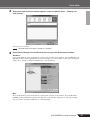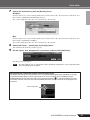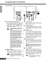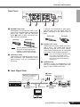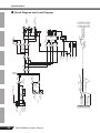
1
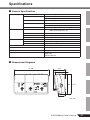
USB AUDIO INTERFACE
EN
DE
FR
ES
RU
JA
COMPLIANCE INFORMATION STATEMENT
(DECLARATION OF CONFORMITY PROCEDURE)
Responsible Party :
Address :
Telephone :
Type of Equipment :
Model Name :
Yamaha Corporation of America
6600 Orangethorpe Ave., Buena Park, Calif. 90620
714-522-9011
COMPUTER RECORDING SYSTEM
AUDIOGRAM 3
This device complies with Part 15 of the FCC Rules.
Operation is subject to the following two conditions:
1) this device may not cause harmful interference, and
2) this device must accept any interference received including interference that may cause undesired operation.
See user manual instructions if interference to radio reception is suspected.
* This applies only to products distributed by YAMAHA CORPORATION OF AMERICA.
(FCC DoC)
FCC INFORMATION (U.S.A.)
1. IMPORTANT NOTICE: DO NOT MODIFY THIS UNIT!
This product, when installed as indicated in
the instructions contained in this manual,
meets FCC requirements. Modifications not
expressly approved by Yamaha may void your
authority, granted by the FCC, to use the
product.
2. IMPORTANT: When connecting this product to accessories and/or another product use
only high quality shielded cables. Cable/s
supplied with this product MUST be used. Follow all installation instructions. Failure to follow instructions could void your FCC
authorization to use this product in the USA.
3. NOTE: This product has been tested and
found to comply with the requirements listed
in FCC Regulations, Part 15 for Class “B” digital devices. Compliance with these requirements provides a reasonable level of
assurance that your use of this product in a
residential environment will not result in harmful interference with other electronic devices.
This equipment generates/uses radio frequencies and, if not installed and used
according to the instructions found in the
users manual, may cause interference harmful to the operation of other electronic devices.
Compliance with FCC regulations does not
guarantee that interference will not occur in all
installations. If this product is found to be the
source of interference, which can be determined by turning the unit “OFF” and “ON”,
please try to eliminate the problem by using
one of the following measures:
Relocate either this product or the device that
is being affected by the interference.
Utilize power outlets that are on different
branch (circuit breaker or fuse) circuits or
install AC line filter/s.
In the case of radio or TV interference, relocate/reorient the antenna. If the antenna leadin is 300 ohm ribbon lead, change the lead-in
to co-axial type cable.
If these corrective measures do not produce
satisfactory results, please contact the local
retailer authorized to distribute this type of
product. If you can not locate the appropriate
retailer, please contact Yamaha Corporation of
America, Electronic Service Division, 6600
Orangethorpe Ave, Buena Park, CA90620
The above statements apply ONLY to those
products distributed by Yamaha Corporation
of America or its subsidiaries.
* This applies only to products distributed by YAMAHA CORPORATION OF AMERICA.
(class b korea)
2
AUDIOGRAM 3 Owner’s Manual
(class B)
PRECAUTIONS
PLEASE READ CAREFULLY BEFORE PROCEEDING
* Please keep this manual in a safe place for future reference.
WARNING
Always follow the basic precautions listed below to avoid the possibility of serious injury or even death from
electrical shock, short-circuiting, damages, fire or other hazards. These precautions include, but are not
limited to, the following:
Do not open
Water warning
• Do not open the device or attempt to disassemble the internal
parts or modify them in any way. The device contains no
user-serviceable parts. If it should appear to be
malfunctioning, discontinue use immediately and have it
inspected by qualified Yamaha service personnel.
• Do not expose the device to rain, use it near water or in damp
or wet conditions, or place containers on it containing
liquids which might spill into any openings. If any liquid
such as water seeps into the device, unplug the USB cable
from this device immediately. Then have the device inspected
by qualified Yamaha service personnel.
• Never insert or remove a USB cable with wet hands.
CAUTION
Always follow the basic precautions listed below to avoid the possibility of physical injury to you or others,
or damage to the device or other property. These precautions include, but are not limited to, the following:
Location
Handling caution
• Before moving the device, remove all connected cables.
• Avoid setting all volume controls to their maximum.
Depending on the condition of the connected devices, doing
so may cause feedback and may damage the speakers.
• Do not expose the device to excessive dust or vibrations, or
extreme cold or heat (such as in direct sunlight, near a
heater, or in a car during the day) to prevent the possibility of
panel disfiguration or damage to the internal components.
• Do not place the device in an unstable position where it
might accidentally fall over.
• Do not use the device in the vicinity of a TV, radio, stereo
equipment, mobile phone, or other electric devices. Doing so
may result in noise, both in the device itself and in the TV or
radio next to it.
Connections
• Before connecting the device to other devices, turn off the
power for all devices. Before turning the power on or off for
all devices, set all volume levels to minimum.
• When turning on the AC power in your audio system, always
turn on monitor speakers LAST, to avoid speaker damage.
When turning the power off, monitor speakers should be
turned off FIRST for the same reason.
• Do not insert your fingers or hands in any gaps or openings
on the device.
• Avoid inserting or dropping foreign objects (paper, plastic,
metal, etc.) into any gaps or openings on the device. If this
happens, unplug the USB cable from the device immediately.
Then have the device inspected by qualified Yamaha service
personnel.
• Do not use the device or headphones for a long period of
time at a high or uncomfortable volume level, since this can
cause permanent hearing loss. If you experience any hearing
loss or ringing in the ears, consult a physician.
• Do not rest your weight on the device or place heavy objects
on it, and avoid use excessive force on the buttons, switches
or connectors.
(5)-10 1/2
AUDIOGRAM 3 Owner’s Manual
3
MIC/INST jacks (XLR-type) are wired as follows (IEC60268 standard): pin 1: ground, pin 2: hot (+), and pin 3: cold (-).
2
1
3
Yamaha cannot be held responsible for damage caused by improper use or modifications to the device, or data that is lost
or destroyed.
Always unplug the USB cable from a computer or turn off the computer to turn off the device when the device is not in use.
The performance of components with moving contacts, such as switches, volume controls, and connectors, deteriorates over
time. Consult qualified Yamaha service personnel about replacing defective components.
SPECIAL NOTICES
• This manual is the exclusive copyright of Yamaha Corporation.
• Copying of the software or reproduction of this manual in whole or in part by any means is expressly forbidden without the
written consent of the manufacturer.
• Yamaha makes no representations or warranties with regard to the use of the software and documentation and cannot be
held responsible for the results of the use of this manual and the software.
• This disk containing the software is not meant for use with an audio/visual system (CD player, DVD player, etc.). Do not
attempt to use the disk on equipment other than a computer.
• Future upgrades of application and system software and any changes in specifications and functions will be announced
separately.
• The screen displays as illustrated in this manual are for instructional purposes, and may appear somewhat different from the
screens which appear on your computer.
The illustrations and LCD screens as shown in this manual are for instructional purposes only, and may appear somewhat
different from those on your instrument.
This product incorporates and bundles computer programs and contents in which Yamaha owns copyrights or with respect to
which it has license to use others' copyrights. Such copyrighted materials include, without limitation, all computer software,
music data, etc. Any unauthorized use of such programs and contents outside of personal use is not permitted under relevant
laws. Any violation of copyright has legal consequences. DON'T MAKE, DISTRIBUTE OR USE ILLEGAL COPIES.
• Windows is a registered trademark of Microsoft® Corporation in the United States and other countries.
• Apple, Mac and Macintosh are trademarks of Apple Inc., registered in the U.S. and other countries.
• The company names and product names in this manual are the trademarks or registered trademarks of their respective
companies.
* Specifications and descriptions in this owner’s manual are for information purposes only. Yamaha Corp. reserves the right
to change or modify products or specifications at any time without prior notice. Since specifications, equipment or options
may not be the same in every locale, please check with your Yamaha dealer.
4
AUDIOGRAM 3 Owner’s Manual
Introduction
Thank you for choosing a Yamaha AUDIOGRAM 3 Computer Recording System. The AUDIOGRAM 3 is a USB audio interface for digital audio recording. With the AUDIOGRAM 3 and
your personal computer you have the basic elements of a high-performance computer recording
system that is easy to set up and operate.
Please read through this manual carefully before beginning use, so that you will be able to take
full advantage of your interface’s superlative features and enjoy trouble-free operation for years
to come. After reading the manual, please store it in a safe place.
Contents
Introduction.................................................................................... 5
Contents.......................................................................................... 5
Features.......................................................................................... 6
Setup............................................................................................... 7
Quick Guide ................................................................................... 8
1. Cubase AI Download .................................................................. 8
2. Connecting to the AUDIOGRAM interface.................................. 8
3. Powering Up the System ............................................................ 9
4. Adjusting Level.......................................................................... 10
5. Audio Setup of the Software ..................................................... 10
Controls and Functions .............................................................. 14
Input Signal Flow .......................................................................... 15
Troubleshooting .......................................................................... 16
Specifications .............................................................................. 23
General Specifications .................................................................. 23
Dimensional Diagrams.................................................................. 23
Block Diagram and Level Diagram ............................................... 24
AUDIOGRAM 3 Owner’s Manual
5
Introduction
Features
Connect To Your Computer via a Single USB Cable (page 8)
The AUDIOGRAM interface connects to your computer via the supplied USB cable. Stereo audio
data is transferred in both directions—from the interface to the computer, and vice-versa—via the
USB connection (44.1 kHz or 48 kHz sampling frequency).
No Driver Installation Required (page 8)
The AUDIOGRAM system uses the standard drivers included in your computer’s operating system,
so there’s no need to install any extra driver software.
48V Phantom Power (page 14)
A PHANTOM switch supplies +48V phantom power to the channel 1 microphone input, so you can
use high-quality phantom-powered condenser microphones for superior recording quality.
Accessories
• Cubase AI Download Instructions
• USB cable
• Owner’s Manual (this book)
6
AUDIOGRAM 3 Owner’s Manual
Setup
Be sure to turn the PHANTOM
+48V switch (★) on when
using a phantom-powered
condenser microphone.
Microphone
Keyboard, etc.
Audio system
Headphones
USB cable
To connect a device such as a
microphone:
Cubase AI
Computer
To connect an instrument such
as an electric guitar or bass:
AUDIOGRAM 3 Owner’s Manual
7
Quick Guide
This quick setup and operation guide covers operations from downloading the Cubase AI
software to setting up the audio configuration in the software. While going through this
section you might find it useful to also refer to the “Controls and Functions” section on page
14, as well as the pdf manual supplied with the Cubase AI software.
Step
1
Cubase AI Download
We are offering Cubase AI free for downloading via website, specifically for customers who have
purchased Audiogram series. For detailed instructions on downloading, access the URL shown
in the Cubase AI Download Instructions leaflet.
Step
2
Connecting to the AUDIOGRAM interface
Be sure to turn the PHANTOM +48V switch on when
using a phantom-powered
condenser microphone.
LEVEL controls
8
OUT LEVEL control
1
Turn all gear that is to be connected to the AUDIOGRAM off or to standby mode (except the
computer), and set the LEVEL controls and OUT LEVEL control to their minimum settings.
2
Connect microphones and/or instruments.
For details on making connections refer to the “Setup” section on page 7 and the “Controls and Functions” section on page 14.
3
Set the MIC/INST switch according to the type of device connected to channel 1.
Select MIC (
) if a microphone is connected, or INST (
) if a guitar or similar instrument is connected.
AUDIOGRAM 3 Owner’s Manual
Quick Guide
Step
3
Powering Up the System
To prevent loud pops and noises, turn on the power to your sound gear starting with the sources
(instruments, CD players, etc.) and ending with the audio system (monitor speakers).
1
2
Turn on the instruments and microphones.
If you are using a condenser microphone for the channel 1, turn on the PHANTOM +48V
switch.
Observe the following precautions when turning on phantom power.
CAUTION
• Make sure that the PHANTOM +48V switch is off when phantom power is not
needed.
• When turning the switch on, be sure that only a condenser microphone is connected to the MIC/INST input jack. Other devices may be damaged if connected to
phantom power. This precaution does not apply to balanced dynamic microphones
or instruments with the phone jack, however, as these will not be affected by phantom power.
• To prevent damage to speakers, be sure to turn off audio system (monitor speakers)
before turning this switch on or off. We also recommend that you set the OUT
LEVEL control to the minimum position before operating this switch to avoid the
risk of loud noises that could cause hearing loss or device damage.
3
Connect the AUDIOGRAM interface to your computer using the supplied USB cable.
The POWER indicator will light to indicate that power is being applied to the AUDIOGRAM interface.
USB Connection Precautions
Be sure to observe the following points when connecting to the computer's USB interface.
Failure to observe these rules can result in computer freezes/hang-ups and possibly data loss
or corruption. If the instrument or computer does hang up, restart the application or computer.
• Be sure to wake the computer from sleep/suspended/standby mode before
making a connection to the computer’s USB connector.
CAUTION
• Always quit all applications running on the computer before connecting or disconnecting the USB cable.
• Wait at least 6 seconds between connecting or disconnecting the USB cable.
When connecting or disconnecting the USB cable be sure to turn the OUT LEVEL control all the way down.
CAUTION
NOTE
4
The first time you connect to the computer’s USB connector, or change the connection
to a different USB port, a driver installation display may appear. If this occurs, wait until
the installation is complete before proceeding.
Turn the power to the audio system (monitor speakers).
AUDIOGRAM 3 Owner’s Manual
9
Quick Guide
Step
1
4
Adjusting Level
Adjust the volume on all instruments that are connected to the AUDIOGRAM interface.
Set the OUT LEVEL control to the minimum position. Failure to do so may result in
loud noise bursts that can damage your equipment, your ears, or both.
CAUTION
2
Adjust the channel LEVEL controls so that the level indicator PEAK LED flash briefly on
the highest peak levels.
3
Adjust the overall volume with the OUT LEVEL control while monitoring via headphones
or monitor speakers.
OUT LEVEL control
LEVEL controls
Step
5
Level indicator
Audio Setup of the Software
This section describes the procedure for audio setup of the Cubase AI software.
NOTE
Cubase AI 6 is used for the examples in this manual. For details about other versions of Cubase
AI or Cubase AI operation in general, refer to the PDF manual provided with the software.
Cubase AI Setup
1
Set the computer output to the maximum level.
For details on how to make the setting refer to the “The recorded sound is too low in level.” section in the
“Troubleshooting” on page 16.
2
Launch Cubase AI.
Windows:
Click [Start] → [All Program] → [Steinberg Cubase AI *] → [Cubase AI *] to launch the program. (“*”
indicates where the version number appears in the actual icon name.)
NOTE If the ASIO Direct Sound Full Duplex Driver dialog window appears, click [OK].
Mac:
Double-click the [Application] → [Cubase AI *]. (“*” indicates where the version number appears in the
actual icon name.)
NOTE
10
• If you specified a file destination when installing the Cubase AI software, launch the application from that location.
• Create a Cubase AI shortcut or alias on your desktop so you can easily launch the program when required.
AUDIOGRAM 3 Owner’s Manual
Quick Guide
3
When the Project Assistant window appears, select the [More] menu → [Empty] and
click [Create].
A new project is created.
NOTE
4
Recorded Cubase AI data is stored as a “Project.”.
Select [Device Setup] from the [Devices] menu to open the Device Setup window.
Windows:
Select [VST Audio System] in the [Devices] field on the left side of the window. Select [ASIO DirectX
Full Duplex Driver] in the [ASIO Driver] field on the right side of the window. A dialog box will appear
asking “Do you want to switch the ASIO driver?”. Click [Switch].
Mac:
Select [VST Audio System] in the [Devices] field on the left side of the window. Select [USB Audio
CODEC] in the [ASIO Driver] field on the right side of the window. A dialog box will appear asking
“Do you want to switch the ASIO driver?”. Click [Switch].
AUDIOGRAM 3 Owner’s Manual
11
Quick Guide
5
Select [ASIO DirectX Full Duplex Driver](Windows), [USB Audio CODEC](Mac) in the
[Devices] field on the left side of the Device Setup window, and click [Control Panel] on
the right side of the window.
Windows:
The ASIO Direct Sound Full Duplex Setup dialog box will be displayed. Check only the input port and
output port [USB Audio CODEC] checkbox, and then click [OK] to close the dialog window.
Mac:
The [CoreAudio Device Settings] dialog window appears. Check only the [USB Audio CODEC] checkbox in both “Input” and “Output” of the [Input/Output Configuration] field. Click [Close] to close the
dialog window.
6
Make sure that “USB Audio CODEC 1/2”(Windows), “Front Left/Front Right” (Mac) are
shown in the [Port System Name] field, and check the [Visible] column in the Device
Setup window. Click [OK] to close the window.
NOTE
12
If the [Port System Name] field does not change, close and restart the Cubase AI, then open
the Device Setup window.
AUDIOGRAM 3 Owner’s Manual
Quick Guide
7
Select [VST Connections] from the [Devices] menu.
Windows:
If “Not Connected” is selected in the [Audio Device] field, click on the “Not Connected” indication, and
then switch to [ASIO DirectX Full Duplex Driver].
Also set the [Outputs] in the same way, and then close the window.
Mac:
If “Not Connected” is selected in the [Audio Device] field, click on the “Not Connected” indication, and
then switch to [USB Audio CODEC].
Also set the [Outputs] in the same way, and then close the window.
8
Select [Add Track] → [Audio] from the [Project] menu.
The Add Audio Track dialog window appears.
9
Set the “Count” and “Configuration” parameters, and then click [Add Track].
The added tracks will appear.
NOTE
You will normally use a stereo track when recording synthesizers, and a monaural track
when recording vocals or guitars.
Recording with maximum quality and minimum noise:
For optimum sound quality with minimum noise, the AUDIOGRAM signal levels should be set as high
as possible without clipping. Check signal levels to be sent to Cubase AI for recording using the
AUDIOGRAM level indicators while the Cubase monitoring button ( ) is turned off. Adjust the channel LEVEL controls so that the level indicator PEAK LEDs flash only occasionally on the highest input
transients.
Monitoring button
AUDIOGRAM 3 Owner’s Manual
13
Controls and Functions
Control Panel
u
q
ew
1 PHANTOM +48V Switch/Indicator
This switch toggles phantom power on and
off. If you set the switch on (
), the
AUDIOGRAM supplies phantom power to
the MIC/INST jack (XLR-type) 8. Turn this
switch on when using a phantom-powered
condenser microphone.
CAUTION
• Be sure to leave this switch off
(
) if you do not need phantom
power.
• When turning the switch on, be
sure that only a condenser microphone is connected to the MIC/
INST input jack. Other devices
may be damaged if connected to
phantom power. This precaution
does not apply to balanced
dynamic microphones or instruments with the phone jack, however, as these will not be affected
by phantom power.
• To prevent damage to speakers,
be sure to turn off audio system
(monitor speakers) before turning this switch on or off. We also
recommend that you set the OUT
LEVEL control to the minimum
position. Neglect of these precautions may result in large
noise bursts that may damage
your equipment, your ears, or
both.
2 MIC/INST Switch
Set this switch according to the type of
device connected. Select MIC (
) if a
microphone is connected, or INST (
) if
an electric guitar or bass is connected.
If a device is not connected to the
NOTE
MIC/INST jack, set this switch to
MIC (
). Otherwise noise may
occur.
14
AUDIOGRAM 3 Owner’s Manual
e
t
yr
3 LEVEL Controls
Adjusts the level of the channel signal. Use
these controls to adjust the balance
between the channels.
4 POWER Indicator
This indicator lights when power is applied
to the AUDIOGRAM interface via the USB
cable (supplied) that connects it to the
computer.
5 Level Indicators
These indicators show signal levels prior to
the OUT LEVEL control 6. The SIGNAL
LED lights when a signal is present, and the
PEAK LED lights when the signal reaches
or exceeds clipping level. Adjust the input
channel LEVEL controls 3 so that the
PEAK LEDs flash only briefly on occasional
high-level peaks or not at all.
6 OUT LEVEL Control
Adjusts the signal level sent to the STEREO OUT jacks 0. This allows you to
adjust the overall volume without changing
the relative volume balance among the
channels.
CAUTION
When connecting or disconnecting
the USB or audio cables be sure to
turn the OUT LEVEL control all the
way down.
7 USB Connector
Connects the AUDIOGRAM interface to a
USB port on your computer via the supplied USB cable. In addition to transferring
audio data between the AUDIOGRAM
interface and the computer, the USB cable
supplies power from the computer to the
AUDIOGRAM interface.
Yamaha recommends that you
NOTE
use a USB cable with a length of
1.5 meter or less.
Controls and Functions
Rear Panel
!1
!0
o
8 MIC/INST Input Jack
If devices are connected to both phone
and pin jacks, only the signal from the
device connected to the phone jacks is
input.
Microphones and instruments such as guitars can be connected here using XLR or
phone jack cables. Set the MIC/INST
switch 2 to MIC or INST according to the
type of device connected.
XLR-type
i
Pin-type
Phone-type
Phone-type
0 STEREO OUT Jacks
NOTE
These output the mixed signal from channels 1 and 2. The output level can be
adjusted using the OUT LEVEL control.
These jacks would typically be connected
to an audio system (monitor speakers).
You can directly connect an electric guitar or bass without the
need for a separate DI (Direct
Injection) box or amp simulator.
NOTE
9 LINE Input Jacks
These inputs are intended mainly for use
with instruments and equipment having
stereo outputs, such as a synthesizer or
CD player.
You can use either the phone jacks
or pin jacks but not both at the
same time. If both jacks are used,
the signal is only output from the
phone jacks.
A PHONES Jack
Connects a pair of headphones to this
jack. The PHONES jack outputs the same
signal as the STEREO OUT jacks.
■ Input Signal Flow
5 Level
indicator
Adjust the recording level
as well as the balance
between channels.
Input
3 LEVEL Record
controls
Playback
Adjusts the
monitor level.
6 OUT LEVEL
control
Output
Cubase AI
AUDIOGRAM 3 Owner’s Manual
15
Troubleshooting
The AUDIOGRAM interface won’t turn on.
❑ Is the included USB cable properly plugged into the interface and a computer?
The system doesn’t work properly.
❑ Are the USB cable and all necessary audio cables properly connected?
❑ Are you using a USB hub?
USB hubs can interfere with proper operation, so try connecting the AUDIOGRAM interface
directly to a USB port on the computer. If the computer has multiple USB ports, try a different
USB port.
❑ Are you using other USB devices at the same time?
If so, try removing the other device(s) and connecting only the Yamaha USB device.
The Input ports are not shown (Windows 8/7/Vista)
❑ Is the sound input of your computer operating system assigned properly?
1. Double-click the “Sound” icon in the [Control Panel] to open the “Sound” dialog window.
2. Click the “Recording” tab, right-click the “USB Audio CODEC” icon and select “Properties.”
3. Click the “Advanced” tab, then select “2 channel, 16 bit, 44100 Hz (CD Quality)” or “2 channel,
16 bit, 48000 Hz (DVD Quality)” in the “Default Format” field.
No sound.
❑ Are your speaker cables connected properly, or are they shorted?
❑ Are the volume controls of your sources, audio devices, applications software, computer operating system, etc., set at appropriate levels?
❑ Is the output of your computer operating system muted?
❑ Do you have several applications running at the same time?
Be sure to quit all applications you are not using.
❑ Is the sound output of your computer operating system assigned properly?
Windows 8/7/Vista:
1. Double-click the “Sound” icon in the [Control Panel] to open the “Sound” dialog window.
2. Click the “Playback” tab and check whether the “USB Audio CODEC” icon is checked.
If not, right-click the “USB Audio CODEC” icon and select “Set as Default Device.”
3. Click the [Recording] tab and check whether the “USB Audio CODEC” icon is checked.
If not, right-click the “USB Audio CODEC” icon and select “Set as Default Device.”
Windows XP:
1. From the [START] menu click [Control Panel], then double-click the “Sounds and Audio
Devices” icon to open the “Sounds and Audio Devices Properties” dialog window.
2. Click the “Audio” tab.
3. Set “Sound playback: Default device” and “Sound recording: Default device” to “USB Audio
CODEC.”
4. Click [OK].
16
AUDIOGRAM 3 Owner’s Manual
Troubleshooting
Mac:
1. Select “System Preferences ...” and then select “Sound” to open the “Sound” dialog window.
2. Click the “Input” tab and under “Choose a device for sound input” select “USB Audio
CODEC”.
3. Click the “Output” tab and under “Choose a device for sound output” select “USB Audio
CODEC”.
❑ Is the sound output of the Cubase AI application assigned properly?
For setup details refer to page 8 of the Quick Guide.
The recorded sound is too low in level.
❑ Is the computer’s output level setting too low?
We recommend that you set the computer output to the maximum level and mute the computer’s
internal speaker.
Windows 8/7/Vista:
1. Double-click the “Sound” icon in the [Control Panel] to open the “Sound” dialog window.
2. Click the “Playback” tab, right-click the “USB Audio CODEC” icon and select “Properties”.
3. Click the “Levels” tab, then set the volume slider to its maximum level.
Close the “Properties” dialog window.
4. Click the “Sounds” tab in the “Sound” dialog window, then select “No sounds” in the “Sound
Scheme.”
Windows XP:
1. From the [START] menu click [Control Panel], then double-click the “Sounds and Audio
Devices” icon to open the “Sounds and Audio Devices Properties” dialog window.
2. Click the “Volume” tab.
3. Set “Device volume” to “High.”
4. Click the “Sound” tab.
5. Select “No sound” in the “Sound scheme.”
Mac:
1. Select [System Preferences ...] and then select “Sound” to open the “Sound” dialog window.
2. Click the “Output” tab and set the volume slider at the bottom of the window to its maximum
level.
3. Click the “Sound Effect” tab and set the volume slider of the “Alert volume” slider to its minimum level.
❑ Have you connected or disconnected the USB cable while Cubase AI is running?
Doing so can sometimes cause the Windows output level to be reset to its default level. Check
and raise the output level if necessary.
AUDIOGRAM 3 Owner’s Manual
17
Troubleshooting
The sound is intermittent or distorted.
❑ Is the PEAK LED flashing red?
You might have to lower LEVEL control levels to avoid distortion.
❑ Are any other applications, device drivers, or USB devices (scanners, printers, etc.) running at
the same time?
Be sure to quit all applications you are not using.
❑ Are you playing back a large number of audio tracks?
The number of tracks you can play at the same time will depend on the performance of the computer you are using. You may experience intermittent playback if you exceed your computer’s
capabilities.
❑ Are you recording or playing long continuous sections of audio?
The audio data processing capabilities of your computer will depend on a number of factors
including CPU speed and access to external devices.
On Windows XP computers, changing some settings as outlined below can improve performance.
1. Click [Control Panel] from the [START] menu, and double-click the “Sounds and Audio
Devices” icon to open the “Sounds and Audio Devices Properties” dialog window.
2. Click the “Volume” tab and click “Advanced” in “Speaker settings.” The “Advanced Audio
Properties” dialog window will open.
3. Click the “Performance” tab. Set “Hardware acceleration” to “Full”, and “Sample rate conversion quality” to “Good.”
Don’t change these settings if you are not familiar with your computer’s operating system.
Check that the file system is set properly, and make sure that you have a plenty of free memory
(more than 128 megabytes). If the audio files you are recording or playing are not too large,
changing the virtual memory settings can sometimes improve audio performance.
In some cases it might be necessary to update your hard disk controller, device drivers, or BIOS.
Refer to your computer’s support center or support page on the web for more information.
❑ Try adding memory.
Adding more RAM memory can significantly increase your computer’s audio performance. Refer
to your computer’s owner’s manual for information on installing and setting up extra memory.
There is a delay when playing a software synthesizer via a MIDI keyboard (latency).
❑ Check the URL listed below for the latest information.
http://www.yamaha.com/
18
AUDIOGRAM 3 Owner’s Manual
Specifications
■ General Specifications
Jacks
MIC/INST Input Jack
LINE Input Jacks (L, R)
PHONES Jack
STEREO OUT Jacks (L, R)
Controls
Indicators
USB Connector
MIC/INST Switch
LEVEL Control
PHANTOM +48V Switch
OUT LEVEL Control
Phantom Power
Level Indicators
Power
Power Supply
Dimensions (W x H x D)
Net Weight
Included Accessories
x1
x1
x1
x1
x1
x1
x1
x1
Combo jack (Mic/HiZ)
Phone jacks
RCA pin jacks
Phone jack
Phone jacks
RCA pin jacks
USB 1.1 44.1/48 kHz, 16 bit
MIC: for microphones
INST (Hi-Z): for guitars, etc.
x2
Adjust the level of CH 1, 2
x1
48 V, only for CH1
x1
Adjusts the overall signal
x1
Red
x1
2 points (green, red)
x1
Green
USB bus-powered
180 x 61 x 112 mm
490 g
Cubase AI Download Instructions
USB cable
Owner’s Manual
■ Dimensional Diagrams
W: 180
H: 61
52
2
108 D: 112
36
Unit: mm
AUDIOGRAM 3 Owner’s Manual
23
24
AUDIOGRAM 3 Owner’s Manual
+30dBu
+20dBu
+10dBu
0dBu
–10dBu
–20dBu
–30dBu
–40dBu
–50dBu
–60dBu
MIC B
[–60 to –16dBu]
INST
[–44 to 0dBu]
INPUT 1
MIC A
[–60 to –16dBu]
CH IN MIC Gain: Max [–60dBu]
CH IN INST Gain: Max [–44dBu]
CH IN MIC Gain: Min [–16dBu]
CH IN INST Gain: Min [0dBu]
LINE R
[–34 to +10dBu]
[–6dBu]
Level
(Gain)
[6 to 50dB]
HA
HA
ST CH IN LINE Gain: Max [–34dBu]
Clip Level
[–6dBu]
Level
(Gain)
[10 to 54dB]
HA
ST CH IN LINE Gain: Min [+10dBu]
Clip Level
Hi-Z
PHANTOM (+48V)
MIC/INST
LINE L
[–34 to +10dBu]
INPUT 2
COMBO
SUM
SUM
[–6dBu]
RE
GR
D–
D+
GND
+3.7V
USB
DC-DC
Level (MASTER)
[Nominal: –6dB]
DC-DC
PHONES [0.5mW @ 40ohms]
STEREO OUT [–2dBu]
Clip Level
IN
OUT1
SW_IC EN1
OUT2
EN2
12MHz
USB
REG
[–20dBu]
AUDIO
Vbus (+5V)
LO
SSPND
RO
DC-DC
LPF
LPF
LPF
[–20dBu]
LIN
RIN
+7.5V
RE
GR
[–6dBu]
L R
[–2dBu]
MUTE
BA
BA
DR
LPF
Level
(MASTER)
[–12dBu]
–7.5V
+48V
PHANTOM
+5V
POWER
SUM
SUM
[–6dBu]
DR
PEAK
SIGNAL
STEREO OUT
[–2dBu]
+30dBu
+20dBu
+10dBu
0dBu
–10dBu
–20dBu
–30dBu
–40dBu
–50dBu
–60dBu
PHONES
[0.5mW @ 40ohms]
R
L
Specifications
■ Block Diagram and Level Diagram
STEREO L
STEREO R
MEMO
AUDIOGRAM 3 Owner’s Manual
25
MEMO
26
AUDIOGRAM 3 Owner’s Manual