1
I
in
_nJ s
OWNER'S MANUAL by Rock Wehrmann
Congratulations!
Now, I realize that about 80 percent of all owner's manuals start with that word but, in this case, it's justified.
The fact that you've purchased THE SOURCE says several things about you as a musician:
— You're not afraid of what could be called a "computer-controlled instrument"; rather, you're ready to work
with the advantages presented by a microprocessor-based synthesizer.
— You are quality and cost conscious. THE SOURCE contains a built-in sequencer, arpeggiator and
program sequencer and costs less than some non-programmable synthesizers.
— Finally, and perhaps most importantly, you just want to make good music.
This manual will help you to realize just how versatile an instrument THE SOURCE truly is. Section I will show you
how to use each function on the instrument; Section II explains the theory behind each function and gives tips on
how to use that function more efficiently. Margin comments periodically explain, in detail, points made in the main copy.
After you've read the manual, you should have a good working knowledge of digitally-controlled synthesizers and
you should realize that, rather than producing "robot music," digitally programmable synthesizers take care of
the "busy work" and leave you free to make your own kind of music.
And when you're done with this manual, you'll be ready to earn the congratulations which really count —
the applause of your friends and audiences for making great music with THE SOURCE.
Good playing,
Rock Wehrmann
MOOG MUSIC INC.
HI
CONTENTS
SECTION I
Section I Basic Operation
. .
General Maintenance
Setup
Tuning Up
Level 2 Functions
1
Using the Sequencer
2
Using the Arpeggiator
3
Using the Program Sequencer
6
Auto Trig
7
S&H
4
5
Playing Programs
Factory Programs
Performance Controls
1
....
Editing Programs
Storage and Loading of Data
Using the Remaining Level 2 Controls
11
Storing Programs
12
The Hold Control
Repositioning Programs ....
21
23
S&HFitt
£
Ext Trig
12
SECTION II
Section II References
The Analog Synthesizer
Signal Sources
Oscillators
Waveshapes
Modifiers
. .
Emphasis
Contour Amount
KB Track
Voltage-Controlled Amplifier
Keyboard
Contour Generators
Modulation (LFO)
IV
25
The Sequencer
26
The Arpeggiator
26
The Program Sequencer
27
Unconditional Tuning
29
Noise
Controllers
Digital Functions
28
Sync
Voltage-Controlled Filter
25
45
The Incremental Control
46
Interfacing
30
Outputs
30
Inputs
31
Cables
32
Troubleshooting
33
Tuning
34
Cassette Operations
35
Level 2 Functions
35
Incremental Resolution
36
Sound Charts
38
41
Index
*®
^
•
75
SECTION I
BASIC OPERATION
GENERAL MAINTENANCE
The components of the shipping carton for The Source should be saved in case short-distance transport is required.
Do not repack The Source without surrounding it with some kind of plastic (similar to the bag in which it was shipped).
Putting the instrument directly inside the styrofoam end pieces without any protection can generate harmful static changes
and may also damage the wood side pieces. A carrying case is recommended for long-distance transport.
The wood side and trim pieces are walnut. These should be periodically rubbed down with linseed oil
to maintain a rich finish.
The body of the instrument is constructed of brushed aluminum and, when needed, should be cleaned with a slightly damp
(not wet) cloth. The touch panel may be cleaned in the same manner, taking care not to let water accumulate on any surfaces.
The touch panel is highly resistant to all forms of damage except heat. Do not allow open flame or lighted cigarettes
near the touch panel.
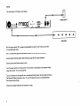
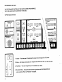
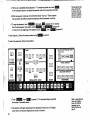
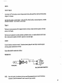
SETUP
The initial setup of The Source is as follows:
o
r
9
sa
9
is
(It
POWER SUPPLY
AMPLIFIER
With the power switch OFF, connect the detachable line cord first to The Source, and then
to a grounded wall socket.
Run a 1/4-inch mono cable from the Source's Audio Out to the amplification system.
Connect desired interface cables. (See Interfacing, page 48, for proper procedures.)
Set amp volume and Source volume to zero.
Turn the power switch on The Source ON. The numeral 1 should appear in the program display
(upper left corner). Turn on the amplifier.
Turn up the volume on the amplifier to an accustomed listening level. With the volume control on
The Source still down, depress any key. Turn up The Source's volume to a comfortable level.
Note these volume settings.
Follow this procedure whenever the instrument is used.
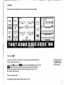
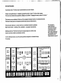
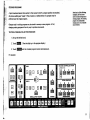
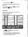
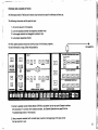
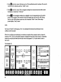
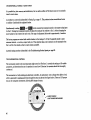
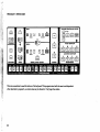
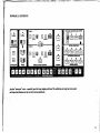
TUNING UP
After The Source has warmed up (4 to 5 minutes), follow this tuning procedure:
VOLTAGE CONTROLLED FILTER
KB TRACK
LOUONE8B CONTOUR
Touch program Q.
Using the rear panel FINE TUNE control, tune The Source to any reliable pitch source
(an organ, piano, tuning fork, etc.).
Touch program Q.Touch the ERBISBI control and, while still holding it down, touch the
E§EH controlin the Mixer section. Now hold down the top key on the keyboard,
and turn the Incremental Controller until the two oscillators are exactly in tune
(the "beating" effect will stop).
Touch any program number.
THE SOURCE IS NOW TUNED UP AND READY TO PLAY.
(If the factory programs
have changed, use the
tuning procedure listed
in the Troubleshooting
section on page 56.)
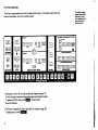
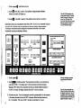
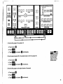
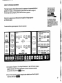
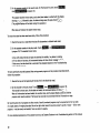
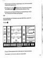
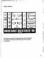
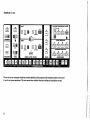
PLAYING PROGRAMS
Touching a program
To call up a programmed sound, touch the appropriate program. If the selected program does not
position immediately
resets every circuit
of the analog synthe
sizer and resets all
digital functions.
come up immediately, one of two conditions exists:
CONTROLLED FILTER
KB THACK
LOUDNEBB CONTOUR
1. The Source is in the HOLD mode (see Storing Programs on page 11).
If this is the case, a semi-colon figure will appear in the Program Display.
To escape the HOLD mode, touch HtSHBI. The semi-colon
figure will disappear.
2. The Source is operating in Level 2 (see Level 2 Functions on page 15).
To escape Level 2, touch LEVEL 1
FACTORY PROGRAMS
The factory programs (programs in memory when The Source is shipped) are:
1. Lead 1: a "fat" lead sound, reminiscent of the Minimoog.
2. Lead 2: a guitarlike lead voice; effective with pitch bending.
3. Horn: a simulation of brass instruments; realistic over a wide range.
4. Flute: voiced with tremolo, this program sounds best with the modulation wheel set at approximately 75%.
5. Clav Bass: a bright, funky bass voice with a "plucked" sound.
6. Vibes: this voice has a touch-dependent envelope; playing and holding a key produces a different sound than does
"tapping" and releasing a key. Set the modulation wheel to 75% for tremolo.
7. String Bass: a mellow bass sound with the touch-dependent envelope described in program 6.
8. Harpsichord: a bright, plucked sound.
9. Organ: this voice uses single triggering for a "percussive" attack when desired.
10. Trill Voice: the modulation wheel will "tune" the upper note of a trill.
11. Taurus: the same rich, deep sound as the Moog Taurus Pedal Synthesizer
12. Synthevox: a resonant singing lead-line sound.
13. Sax: a nasal, biting sound characteristic of an alto or soprano saxophone.
14. Wind: this voice uses noise as a signal source. Turn the modulation wheel up to full for a "sweeping" effect.
15. Snare Drum: different areas of the keyboard will produce differently "tuned" drums.
16. A duplication of program 1. Program 16 can be used as a holding position for rearrangement of program positions.
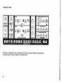
PERFORMANCE CONTROLS
THE PERFORMANCE CONTROLS ON THE SOURCE ARE NOT PROGRAMMABLE.
THEY ARE ALWAYS ACTIVE AND READY TO BE USED.
The Performance Controls are:
X/OLTAOE CONTROLLED FILTER
I
32' I
I IS' I
FOOTAGE
I SING I
0
El 0 CM
I KB TRACK
II
CUTOFF | |EMPHASIS| | "gjJJTR
IMULT
FILTER CONTOUR
TRIGGER
HE
FOOTAGE
0 0
ONESS CONTOUR
WAVESHA
I interval!
OSCILLATOR
MEMORY
STOP
CONTINUE.
PLAY 1
PLAT 2
BANK
ARPEGGIO
SSH
SSHFILT AUTOTfllQ
E
DBBD HQDQBIiEliIliB
PRQGRAM5
1. Volume - Final master gain. This determines the output level of all signals from The Source.
2. Octave - The Octave controls (Zero and +1) transpose the oscillators and filter up or down an octave.
3. Pitch Wheel - This wheel changes the pitch of the oscillators up or down.
4. Modulation Wheel - Moving this wheel up (towards the volume control) introduces vibrato or
other modulation effects {see "Modulation" on page 38).
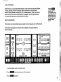
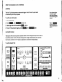
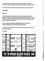
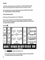
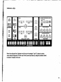
EDITING PROGRAMS
As previously shown, The Source may be used exclusively as a preset synthesizer.
However, during performance, it is desirable to change the quality of a sound. For this and other reasons,
The Source has extensive editing capabilities. Editing may be defined as "changing the memory values of a function.'
the functions on any synthesizer fall into one of two categories: Switching functions or incremental functions.
The Source's touch panel and incremental controller allow access to all these functions.
Hie touch panel is a
The touch panel is laid out in a manner similar to a conventional monophonic synthesizer.
unique instant-access
Major function blocks — oscillators, filter, modulation - are grouped in visual sections.
entry system. The Source's
microprocessor recognizes
an entry (touch) on the
panel in under 3 milliseconds.
For an explanation of touch
panel functions, see The
Switching controls on The Source touch panel are square-shaped and are either orange
(memory controls) or light blue (synthesizer controls).
Analog Synthesizer on page 25.
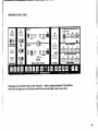
To edit a switching function, touch the control positions corresponding to the desired change.
For example:
VOLTAQS CONTROLLED FILTER
I
I KB TRACK
1/2 I
SING
I CUTOFF
I EMPHASIS!
iMULTl
FILTER CONTOUR
TRIGGER
LOUONE8Q
MODIFIERS
MEMORY
HtCl
MtL*
aiur
t-unimuc .£>;
AY1
nwi i
-
-rJ
PIAY2,*
RE
^"_m_ ■.__n^_
;^^Z^/;ii; "^~" * ^^^^_".-^^^^^ - ^^^^_ ,, ..' ^^^^_
PROGRAMS
^^^^HV ^^^^H ' ^^■H ' ' '
'
^^1^1
fl^^^l
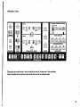
1. Touch program Q - Hold down any key.
2. Touch LI in the OSC 1 section. The oscillator changes octaves immediately.
(Note that the edit LED tights up.)
The edit LED illuminates after
a front panel control is touched.
While the control is being held
down, the LED shuts off to
show that contact has been made.
When the control is released,
the LED illuminates again.
3. Touch Q?H in the OSC 1 section. (The oscillator returns to the lower octave.)
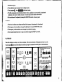
Switching functions are unconditional; either ON or OFF, 16' or 8', etc. Incremental functions
are continually adjustable, and are represented on the touch panel by yellow rectangles.
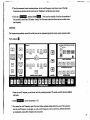
Touching an incremental function assigns the incremental controller to that function.
Incremental functions are adjusted as follows:
VOLTAGE CONTROLLED FILTER
KB TRACK
1. Touch programQ.
2. Touch |5J3JJJ'n the Mixer section. The incremental controller is now controlling the
Note that touching a program
control cancels all previous
editing.
audio level of OSC 1. The display next to the incremental controller illuminates,
displaying "99." Most of the incremental controls are divided into 100 increments -
0 to 99. In this case, the display indicates that OSC 1 level is at maximum.
3. Hold down any key. Turn the incremental controller counterclockwise. As the numbers
in the display decrease, the level of OSC 1 decreases. When the display shows zero,
Osc 1 is inaudible. The input of OSC 1 has been turned down in the mixer.
8
Note that the incremental con- «>
troller can still turn freely when, y
the display reaches zero. For an '-M
explanation of the characteristics.
of the incremental controller, see'
Digital Functions on page 41,
-
4. Touch PBftW in the Mixer section. The edit LED momentarily goes off (showing
that contact has been made), and the display reads "99f" showing that Osc 2 is at
maximum level. The previous editing (Osc 1 level changed to zero) is kept in memory.
At this point, turning the incremental controller will change the level of Osc 2.
i *
5. "Review" the IZQEEl control in the Mixer section by touching it and noting
Touching an incremental function,
without turning the incremental
controller, will display the current
memory value, but will not change
that value. Controls may be
the display value (in this case, zero).
6. Touch ISSJEI again. If no changes were made in Step 4, the display should now
"reviewed" in rapid succession
read "99." Turn the incremental counterclockwise until the display reads zero.
to get a mental picture of a
particular sound.
Depress any key. No signal is heard. Why?
1. Osc 1 level was set to zero in Step 3. That setting was held in memory.
2. Noise level was proved to have been programmed at zero by reviewing ( Step 5).
3. Current editing displays zero level for Osc 2.
All signal sources are at zero, so no output is heard.
Any incremental control may be reviewed or edited in the same way. For example:
VOLTAGE CONTROLLED FILTER
KB TRACK
9
1. Touch program Q (this cancels all previous editing). Play the keyboard and note the quality of the sound.
2. Review lafliasrivisi in the Filter section. The display reads zero.
3. Touch MlhMdJ in the Filter section. The display reads 41. Turn the incremental controller while repeatedly
striking a key. Note the change in sound quality. At any point, touching another control will hold the last value
of the Cutoff control in memory.
SUMMARY:
1. Touching any front panel synthesizer control puts The Source into Edit mode.
2. When consecutive edit changes are made, all previous editing is held in memory.
3. Switching functions may be edited by direct entry.
4. Incremental functions may be:
a) Reviewed, by touching an incremental control, noting the display value, making no changes, and
proceeding to another control.
b) Edited, by touching an incremental control, changing its value with the incremental controller, and
proceeding to another control.
5. All editing is cancelled by touching a program control.
10
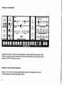
STORING PROGRAMS
Note that in all the following
examples, the final sound
A point mentioned several times earlier in this manual is that if a program position was touched,
all previous editing was "erased." Often, however, an edited version of a program may be
stored in memory began as an
existing program. The existing
program was substantially
changed, and a new, desirable
sound resulted.
preferred over the original program.
Changes made in existing programs may be stored in memory as new programs. In fact,
changing existing programs is the only way to produce new sounds.
TO STORE A PROGRAM, FOLLOW THIS PROCEDURE:
1. Set up the desired sound.
2. Touch ■SOTBM . (Two dots light up in the program display.)
3. Touch KKtiaa and the intended program location simultaneously.
For example:
VOLTAGE CONTROLLED FILTER
KB TRACK
26
73
27
FILTER
0
65
42
11
0
53
99
0
MODIFIERS
11
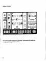
1. Touch program
2. Using the previous sound chart, edit all indicated controls by touching the appropriate
switching functions and adjusting each incremental function.
Note that program 16
is a duplication of
program 1. No original
programs are lost during
this procedure.
3. When all indicated editing has been completed, follow the storing procedure on page 11
to store the new program at program
4. Now touch program Q . The editing in the previous sound chart equals the values
in memory for factory program 2, so the program stored in 16 should duplicate
the program in 2.
THE HOLD CONTROL
The Hold control does two things: (1) freezes the front panel (so no further editing is possible),
and (2) activates the Store control. (Normally, the Store control is "dead" to prevent
accidental erasure of programs.)
While the Hold control is active, other programs may be momentarily reviewed by touching
and holding the program control. When the program control is released, The Source returns
to the sound set up on the front panel.
The Hold control is reversible - touching it again will turn it "on" if it is "off," or vice versa.
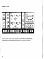
REPOSITIONING PROGRAMS
For a particular performance, the programs may need to be put in a different order, so it's a good idea to reserve
program [0 as a kind of "holding" position to allow repositioning of programs.
To switch any two program positions (4 and 8, for example), follow the procedure outlined with the next
sound chart.
12
Active Hold status is
indicated by two
illuminated dots in
the program display.
VOLTAGE CONTROLLED FILTER
KB TRACK
CUTOFF
EMPHASIS
~"~
FILTER CONTOUR
WAVESHAPE
LQUDNEBB CONTOUR
INTERVAL
0
OSCILLATOR
BANK
I
|_
S
MODIFIERS
1. Move the first program (4) to position 16.
a) Touch program Q .
b) Touch HUHI .
c) Touch Rmiaai and program
simultaneously.
2. Move the second program (8) to the original location of the first program (4).
a) Touch program Q .
Touching
then
QQE9
control simultaneously
will store the current
front panel settings
(edited or not) at the
indicated program.
c) Touch QyQQJ and program Q simultaneously.
3. Move the first program to the original location of the second.
a) Touch program
c) Touch EHSEEi and program El simultaneously.
13
SUMMARY:
1. To store a program, touch |i[*]321 , then touch pifKM and a
PROGRAM NUMBER simultaneously.
2. The iSMWiJ control allows reviewing of existing programs and is reversible.
3. Reserving program [Q as a "holding" position allows relocation of programs.
14
LEVEL 2 FUNCTIONS
Since The Source is a microprocessor-based instrument, a single control may have several different
Touching
converts the program
functions, depending on the level of operation. Many of the controls on The Source have
selectors to the
Level 2 functions written
in small letters above the
program number. After
the Level 2 function has
been activated, control
alternate functions, accessed by entering Level 2, an "expanded-operation" mode. Level 2 allows
access to real-time functions such as the sequencer, the arpeggiator, and the program sequencer.
The operation of these functions will be explained in this section.
generally reverts to
USING THE SEQUENCER
Level 1.
The Source has a self-contained digital sequencer capable of storing 2 sequences of up to 88 events each.
The Source has been shipped from the factory with two sequences. To play back sequences,
follow this procedure.
VOLTAGE CONTROLLED FILTER
K6 TRACK
A _J
|
0
- I
I
S
^1
I
R
LOUDNEBB CONTOUR
1. Touch the program number of the desired sound.
2. Touch IJQQHS^Iat the lower right corner of the touch panel.
3. Touch lawarJiM (program 5).
15
4. The Source is repeatedly playing Sequence 1. To change the playback rate, touch
in the modulation section, and adjust the sequencer rate with the incremental controller.
The last playback rate
chosen will be held
in memory when the
sequencer is stopped;
5. While the sequencer is playing, the incremental display "counts up." Other programs
may be selected and edited using editing techniques while the sequencer is running.
subsequent sequences
To continue
6. To stop the sequencer, touch ■■»«■«, then touch
l(program 4).
from the last sequencer note played, touch
, then
To restart from the beginning of the sequence, touch
To hear Sequence 2, follow the above procedure using
PLAY 2
will start at this rate.
<Pr°9ram 5).
(program 6).
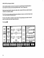
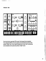
To record new sequences, follow this procedure:
VOLTAQ6 CONTROLLED FILTER
KB TRACK
A ^J
I'
0^1
|_
S
I
1
H
LOUONE8B CONTOUR
1. Touch U3BHJ5I'tnen ':<a— (program 1). The incremental display shows 88,
the number of recordable events.
Rests, or spaces between
notes, are counted as
events. For efficient
sequencer use, see
2. The sequencer will begin recording with the depression of the first key. The display
counts down, continuously displaying the number of events left.
16
Digital Functions on
page 41.
(program 3).
3. At the end of the last desired event, touch
To hear a recorded sequence, follow the sequence playback procedure. The sequence plays back at the last
sequencer rate entered.
To record the second sequence, follow the above procedure using
(program 2). Playback of the
second sequence is controlled by MUWixmfM (program 6).
USING THE ARPEGGIATOR
The arpeggiator can be thought of as a kind of "instant sequencer." It performs many of the functions
of the sequencer, but uses none of the sequencer memory.
To use the arpeggiator, proceed as follows:
VOLTAGE COIMTBOLJ-ED FILTER
KB TRACK
n [a] |7B
A
FOOTAGE
WAVESHAPE
- I
I
0
^ |
|
S
~l
I '
R
LOUDNEBB CONTOUR
INTERVAL
OBCII.LATOR
BANK
5161718
1. Touch B3SI3SSM'then touch program
(Arpeggio). The incremental display lights up,
displaying the arpeggiator playback rate.
2. Play the notes of the desired musical pattern one by one without repeating the first note played.
As keys are depressed, the display counts down from 24. The repetition of the first note will indicate
the end of the pattern and switch the arpeggiator to the playback mode.
17
First note is repeated;
Arpeggiator immediately begins
Example:
metronomic playback of first eight notes.
I
3. To change the playback rate while the arpeggiator is running, touch |j&3|3 in the
modulation section and adjust the playback rate with the incremental controller. While
the arpeggiator is running, The Source is in Level 1; programs may be selected and/or edited.
The last arpeggiator rate
used is held in memory;
the arpeggiator will play
at this rate the next time
it is started.
4. To stop playback, touch QjQ^Q , then EU*m (program 3).
5. To replay the last arpeggio stored, touch QJQ3S 'E3itil3£ISJ9' MWl'then
CONTINUE
6. Touching any key during playback instantly switches the arpeggiator to the record mode.
If, while the arpeggiator
is running, a new pattern
is played on the keyboard
at the current playback
rate, the arpeggiator will
play back the new pattern
with no break in rhythm.
This is an especially power
ful performance feature.
SUMMARY:
1. The arpeggiator records up to 24 notes. The repetition of the first note immediately switches
its function from recording to metronomic playback.
2. Playback of the arpeggiator may be stopped by touching
LEVEL 2
, then HHIJ (program 3).
This does not erase the arpeggio from memory.
3. Touching
EVEL 2 ■ ARPEGGIO ■■ LEVEL 2
and p*«iMiifliiT3 (program 4) will start playback
of the last arpeggio stored.
4. Touching any key, during playback, immediately switches the arpeggiator from playback to record.
18
USING THE PROGRAM SEQUENCER
If the factory sequences
The program sequencer allows different events of the sequencer to be played with different
programs. For example, a 16-note sequence can play the first four notes on program 1,
the next eight notes on program 2, and the last four notes on program 3.
have not been changed,
program sequencing can
be demonstrated
touching
(program 8), then
Each note in a sequence (up to 88 notes) has the capability of being assigned to
Hie information dictating
an individual program.
program changes is stored
concurrently with the sequencer
pitch and duration information;
program changes may also occur
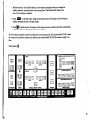
To record with the program sequencer, follow this procedure:
during a rest.
VOLTAQE CONTROLLED FILTER
0 0 [Hi
fOOTACI
WAWSMAff
LOUDNCBB COMTOOP
INTERVAL
OSCILLATOR
BANK
MODIFIERS
1. Start playback of Sequence 1. (See Using the Sequencer on page 15.) Practice changing
programs manually as the notes in the sequence are played (the sequence playback
may be slowed using the Mod |i£]13 control).
2. When the final sequence of program changes has been decided, touch the first program
to be heard, then touch
LEVEL 2
19
3. Touch lllSMtl;iafligWi:«iI (program 7). The sequence will play once from
the beginning. As the notes are played, touch programs at the appropriate times.
4. At this point, the sequencer can play back with or without program changes. For playback
with program changes, touch tmi^WtM , then HSBBISHBISHSlSl^n (program 12),
then IJBMH (or QQ^]). F°r Payback without program changes, follow normal sequencer
procedure (see Using the Sequencer on page 15).
5. A different sequence of program changes may be recorded for Sequence 2.
SUMMARY:
1. The program sequencer will automatically change programs when the sequencer is running.
2. The program sequencer is loaded by touching program numbers while the sequencer plays back.
3. Sequencer playback can occur with or without program changes.
20
A program change recorded
at any point in the duration
of a note will occur at the
beginning of that note during
playback. (For efficient
operation, see The Program
Sequencer in the Digital
Functions section on page 45.)
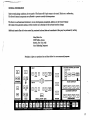
STORAGE AND LOADING OF DATA
All information held in The Source's memory may be stored on tape for reference and later use.
The following information will be saved on tape:
1. All control values for 16 programs.
2. Last two sequences entered (and sequencer playback rate).
3. Last arpeggio entered (and arpeggiator playback rate).
4. Last program sequences entered.
The first cassette operation should be making a copy of the factory programs.
TO CASSETTE
To save information on tape, follow this procedure:
VOLTAGE CONTROLLED FILTER
I
3 0
SMS I
El 0
I KB TRACK
^i r^n u»™^ sn
I
TRIGGER
FILTER CONTOUR
32- I
I 16 I
FOOTAGE
El
El 0
LOUONEBB CONTOUR
WAVESIH
I INTERVAL I
:iLLATOR
STOP
CONTINUE
PlAV
A
;::,- ARPEGGIO
|
|
D
1
I
S|
MODIFIERS
BANK
SfcHFUT r AUTO TRIG ' - EXT. TRIG .
SAVE
■
VEf
PROGRAMS
1. Connect a cassette recorder (Radio Shack CTR-80 or equivalent) to the rear panel Cassette Interface
DIN Connector.(To connect other cassette recorders, see Cassette Operations on page 55 in the
Troubleshooting section of this manual.)
2. Using a computer cassette (with no leader tape), rewind to the beginning of the tape and set
the tape counter to zero.
21
3. Put the cassette recorder in the record mode. On The Source front panel, touch
then rirflaa«««aB« (program 14).
The cassette recorder's motor starts, and a short blank leader is recorded (with the display
showing^ rj^), followed by data. As data are being saved, the display shows^ □ .
(The program display will be blank during this operation.)
When data are finished, the cassette motor stops.
To ensure that data have been saved accurately, follow this procedure:
1. Rewind the tape to an area before the data file (somewhere in the blank leader area).
LEVEL 2BRHHICASSETTE
VERIFY
2. Put the cassette recorder in the play mode. Touch nxmrnn,
then
(program 15). The cassette's motor starts.
In the verify mode, the data on tape are examined for validity. If any datum is missing,
or if key data are incorrect, the incremental display will show the error message '—' '—' .
If this occurs, the data should be re-recorded. (See Cassette Operations in the Troubleshooting
section of this manual.)
To load a previously recorded cassette (after saving present programs with the procedure described above),
follow this procedure:
1. Rewind the tape to the beginning of the data file (in the blank leader area).
2. Set the recorder to the play mode. Touch iiaMati, then itfcttBiaMMtraiJ (program 16).
The recorder's motor starts. As the data are loaded, the incremental display will show r^
| *
When all information has been loaded, the recorder stops, and the program display comes on with the
program most recently selected. The Source has now been re-programmed with the information on tape.
By recording new sets of programs one after another, literally hundreds of programs may be represented on the two sides
of a single cassette. Arranging these data files in the right order means that an entire concert's worth of music - 120 or more
programs - may be stored, and recalled, from one side of a cassette.
For more detailed explanations of the cassette functions, see Cassette Operations in the Troubleshooting section of this manual
22
USING THE REMAINING LEVEL 2 CONTROLS
AUTO TRIG
The Auto Trig function generates a metronomic trigger at the LFO rate. The pitch heard
Since keyboard voltage
is stored as a digital
is determined by the last key depressed.
value, pitch drift cannot
occur if Auto Trig is left
To use the Auto Trig function:
running.
1. Play the desired key.
2. Touch nxiUWA, then rawiHM (program 12).
When the
function has been acti
vated, control returns to
Level 1.
3. Adjust trigger rate with the modulation psfiii^ control.
4. To shut off the automatic triggering, touch ■■aaaaei , then AUTO TRIG
again.
S&H (SAMPLE & HOLD)
The Sample & Hold function generates successive random control voltage amounts, which are sent to
the oscillators and/or the filter. The rate of change of this voltage is determined by the rate of the
low-frequency oscillator (LFO). Triggers are generated to coincide with voltage changes.
To use the Sample & Hold:
VOLTAGE CONTROLLED FIlXBR
KB TRACK
LOUONE8B CONTOUR
23
1. Play a desired key. (This sets up a general range of frequencies; it has no influence
on the actual frequencies generated.)
2. Touch BSQS3 'then touch QSE1 (program 10).
3. At this point, adjusting the Q^Xl control in the Mod section will change the Sample & Hold
rate and modify the apparent "pattern" of voltage changes.
4. To cancel the Sample & Hold effect, touch ■■Mia»ei. then touch |£fg£]again.
S&HFILT
This control (program 11) routes the random Sample & Hold voltage to the filter alone. The operational
procedure is the same as for program 10 (S & H).
EXT TRIG
If a slave synthesizer is interfaced with The Source (as described in the Interface section of this manual),
its playing status is determined by this switch.
Note: This switch defeats triggers only. The oscillators of the slave synthesizer will always be affected by
The Source's keyboard voltage. Keep this in mind when playing multi-keyboard setups.
A table is provided in Section II that lists the functions and actions of all Level 2 controls.
24
section n
REFERENCES
THE ANALOG SYNTHESIZER
The part of The Source that actually produces sound is a monophonic analog synthesizer. This synthesizer is controlled
by digital devices (explained in Digital Functions on page 41), but the synthesizer itself has many points in common
with existing established models such as the Minimoog.
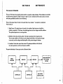
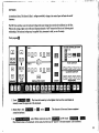
There are three major kinds of circuits in the sound chain of any synthesizer — monophonic or polyphonic.
These circuits are:
1. Signal Sources: The original source of sounds in the synthesizer. Signal sources are classified as
pitched or unpitched. In The Source, the pitched signal sources are two voltage-controlled oscillators.
The unpitched signal source is a noise generator.
2. Modifiers: Circuits that alter the quality of the basic sound produced by the signal sources.
The two main modifiers on The Source are the voltage-controlled filter, which produces changes
in tone color, and the voltage-controlled amplifier, which produces changes in loudness.
3. Controllers: Circuits that control other circuits. The primary controllers are the keyboard,
the contour generators, and the low-frequency oscillator.
The general relationship of these major circuits is illustrated below:
I
((OTHER MODIFIERS '
SIGNAL
OR PLAYBACK
MODIFIER
MODIFIER
SOURCE(S)
I
SYSTEM)
I
t
I
J
,
I
-I
I
r
CONTROLLER
CONTROLLER
i
I
i
(ANY OTHER
I
I CONTROLLERS) {
I
I
25
A synthesizer design may, in theory, incorporate any number of signal sources, modifiers, and/or controllers.
Note, also, that the output of a controller may theoretically be sent to the control input of any voltage controlled device.
The major circuits ("modules") are explained here, roughly in order of importance and occurrence in the signal path.
SIGNAL SOURCES
OSCILLATORS
The Source has two audio oscillators. These oscillators put out electrical signals called waveshapes or waveforms,
illustrated on the waveshape controls. The oscillators generate waveforms continuously. The completion of one waveform
is called a cycle; the number of cycles completed in a specified time period is the oscillator's frequency and is generally
expressed in cycles per second (cps) or Hertz (Hz).
If the oscillator's frequency is between 20Hz and 20,000Hz (20KHz), human ears can perceive it as pitch.
The changes of oscillator frequency produce the different pitches heard from The Source.
The oscillators are voltage-controlled; applying a positive voltage to their control inputs will produce a positive change
in frequency (the pitch will rise).
Touch program 3:
VOLTAGE CONTROLLED FILTER
KB TRACK
26
1. Hold down any key.
2. Touch different octave controls. Note the change in pitch.
3. Touch program Q, then ||£||3iKfiD m t^ie ^^ 2 ration.
4. Turn the incremental control clockwise. Note that Osc 2, in addition to octave controls, has an interval
adjustment. Osc 2 may be tuned as much as two octaves up from the chosen octave control.
5. Both oscillators will be adjusted by turning the FINE TUNE control on the rear panel.
SUMMARY:
1. The Source's oscillators are voltage-controlled; their frequency is determined by the keyboard.
2. The frequency of both oscillators is changed by adjusting the rear panel FINE TUNE control.
3. The frequency of either oscillator can be changed by its OCTAVE controls.
4. Osc 2 may be detuned from Osc 1 by up to 2 octaves by using the INTERVAL control.
WAVESHAPES
The audio oscillators can output one of three waveshapes. The wavefonn selected will determine the basic tone color.
Touch program Q, then touch the indicated controls and, using the incremental control, adjust to the values shown:
VOLTAGE CONTROLLED FILTER
KB TRACK
0
0
fer.
LOUDIME88 CONTOUR
99
27
1. Touch Id in the Osc 1 section. Hold down any key. This is an unfiltered sawtooth waveshape. The sawtooth
waveform is rich in harmonics, and has a "bright" sound.
2. Touch Q in the Osc 1 section. This is a triangular waveshape. It has a harmonic structure unlike acoustic
instruments, so it sounds very " electronic."
3. Touch IliBil . The rectangular waveshape has an adjustable duty cycle (comparative time of the positive
portion of the waveshape). The incremental control will change the duty cycle from 5% to 95%. Setting
the duty cycle at 50% produces a square wave, with a characteristic "hollow" sound. Other settings
produce brighter, "reedy" sounds.
SYNC
Osc 2 may be "locked" to the frequency of Osc 1 by activating the Sync function (located between the two
oscillators on the front panel).
When the two oscillators are synchronized, new waveforms are produced when an attempt is made to change the
frequency of Osc 2. Osc 2 may be statically detuned by changing the Interval and/or Octave controls, or dynamically
detuned by moving the pitch wheel (when the Sync function is programmed "on," the pitch wheel is routed to
Osc 2 only).
Touch program 12:
VOLTAGE CONTROLLED FILTER
KB TRACK
28
1. This factory program is voiced with Sync on. Change the frequency of Osc 2 (with the Octave and Interval
controls) and note the change in tone color.
alternately off and on. No matter how far apart in frequency
2. While holding down a key, switch
on will lock them together, eliminating any "beating."
the two oscillators are, turning
3. Hold down any key and move the pitch wheel. When Sync is on, the pitch wheel becomes a "tone color
wheel." These dynamic tone color changes are useful in performance.
NOISE
Noise is an unpitched signal source. The noise generator outputs a signal called Pink Noise, a composite of low,
mid-range and high frequencies.
Touch program
VOLTAGE CONTROLLED FILTER
I
I K6 TRACK
FILTER CONTOUR
LOUDNEBB CONTOUR
I STORE I
I
OSCIU-ATOR
MEMORY
REC1
RtCZ
stvr
tUNilNUt
flflTi
ruu
nz\.
ri.«»
0
I
I
S
MODIFIERS
^m^uu^u
54 H
^^^.
S&HFILT
^^^^
AUTO TRIG
.^^^^^.
£X1
^^^^B
;ave
^^^^B
verify
SBCTIIMI
loud
_■■
■
■■■^■1
^^^^|
PROGRAMS
1. Play any key. This factory program uses noise as the primary signal source; no single pitch predominates.
Factory programs 4, 14 and 15 use noise as a signal source (in varying intensities).
29
MODIFIERS
A modifier alters or attenuates the basic output of the signal sources. A modifier characteristically has a signal
input and a signal output; the signal from the oscillator(s) and/or noise must "pass through'* the modifier.
There is theoretically no limit to the number of modifiers that may be used in a synthesizer. The Source employs
two: a voltage-controlled filter and a voltage-controlled amplifier.
VOLTAGE-CONTROLLED FILTER
The filter section of The Source changes the tone color of the signal sources.
The Source employs a low-pass filter. As the name implies, this filter passes low frequencies and rejects high
frequencies. The point at which frequencies start to be rejected is called the cutoff frequency. This cutoff frequency
may be adjusted manually or electronically.
Touch program Q :
VOLTAGE CONTROLLED FILTER
I
32' I
I 16' I
FOOTAGE
I SING
[3
I KB TRACK
El 0
IMUL1
TRIGGER
FILTER CONTOUR
32' I
I 11 I
LOUONEBB CONTOUR
FOOTAGE
INTERVAL I
OSCILLATOR
MEMORY
REC1
REC2 :I^'-STGP
CONTINUE
-^-PLAY 1
PLAY Z
■
REC
PlAY
.
MODIFIERS
BANK
ARPEGGIO
S4H
S & H FILT^ AUTO TR(G
EXT.TRIG
SAVE
VERIFY
LOAD
PROGRAMS
1. Touch
CUTOFFiFREQ
in the filter section. Hold down any key.
2. Turn the incremental control clockwise. As the cutoff frequency is set higher, more of the high frequencies
of the oscillator signal are heard, and the sound becomes "brighter."
30
3. Turn the incremental control counterclockwise. As the cutoff frequency is set lower, more of the high
frequencies are rejected, and the sound loses its "brightness" and becomes more muted.
4. Touch the L£UiIfl!l3 position labelled OEQ9
Now turn the controller. Note that the resolution of
the controller is much finer. This makes "tuning" the filter easier when the filter is used as an audio source
(see Emphasis).
EMPHASIS
The frequencies immediately around the cutoff point can be emphasized, giving the sound a nasal, resonant quality.
Touch program
1. Sweep the cutoff frequency up and down (as in the preceding exercise). The sound smoothly becomes brighter
and darker.
2. Touch EMPHASIS ; set the incrementer to 70.
3. Now sweep the cutoff frequency again. Note how higher emphasis settings affect the sound. The harmonics
near the cutoff frequency are stronger, so, as the cutoff frequency moves up and down, different harmonics
are emphasized, making filter changes more pronounced.
31
4. Set IdAIJiHcH^ tn 99. Touch 1^:1 J;ftWM mm. Set IWtlfliUHUnwtlilMB and all Mixer
controls to zero. Play different keys. At maximum emphasis, the filter oscillates and produces a
controllable sine wave.
CONTOUR AMOUNT
The Source's filter is voltage controlled; a positive voltage at its control input raises the cutoff frequency. The
filter accepts voltages from many places on The Source, but the main voltage source is the filter contour generator.
The Contour Amount circuit controls the amount of voltage that goes to the filter from the contour generator.
(The contour generator is explained more fully in the Controllers section beginning on page 35.)
Touch program
VOLTAGE CONTROLLEO FILTER
HK6 TRACK
jfj Ld LJ
OH l£J
FOOTAGE
Iff
CUTOFF I
EMPHASIS
WAVESHAPE
SYNC
| OFF I I ON '
FILTER CONTOUR
2—1
M* 1
[7]
I 16 I
(K) 0
LOUONESS CONTOUR
FOOTAGE
I INTERVALI
OSCILLATOR
MEMORY
REcV".:-
REC2:Vj"'"'STOP
CONTINUE , J'^PtAY 1
PLAY 2
■
REC
-
PLAY.-
I
'" ARPEGGIO,. .' S&H
S& H flLT:>AUTO TRIG
PROGRAMS
l.Set
CONTOUR AMOUNT
P
I
I
S
I
|
EXT.TRIG
:SAVE
'
VERIFY
LOAD
.
^^^
^^^
. *'i CASSETTE
to zero. Hold down any key. There is no change in the brightness of the sound.
2. Now set Q^^QQSSEQQSlSlfl
^° &Q- Hold down any key. The voltage from the contour generator opens
and closes the filter (by raising and lowering the cutoff frequency). Experiment with different settings of the
Contour Amount control.
32
ft
MODIFIERS
BANK
KB TRACK
As mentioned above, The Source's filter is voltage-controlled; voltage at its control input will raise the cutoff
frequency.
The KB Track switches route the keyboard voltage (the same voltage that controls the oscQlators) to the filter.
Without this voltage, higher notes will sound disproportionately "dull" because the filter is not following pitch
relationships. The keyboard voltage may be applied fully, attenuated to half, or cut off entirely.
Touch program
1. Touch
|f<i:fHjfira» ftiaa
Play from the lowest key to the highest. Note how the sound lessens in
intensity toward the upper end of the keyboard.
2. Repeat Step 1 with
KB TRACK
at
and at
The character of the sound is more consistent
across the keyboard.
3. Set QjJ2|QQ33BQQ2J] and all Mixer controls to zero. Set EJjgjEaH to 99. Touch
KB TRACK
Play different notes on the keyboard. In this mode, the filter may be "played" in the same manner as the oscillators.
33
r
VOLTAGE-CONTROLLED AMPLIFIER (VCA)
The Voltage-Controlled Amplifier (VCA) is the final point in The Source's signal path. Like the filter, it responds to
a positive voltage at its control input; the response, however, is an increase not in brightness, but in loudness.
»
The VCA itself is not pictured on the front panel, but its primary controller, the loudness contour generator, is.
Voltage from the loudness contour generator opens and closes the VCA. (The contour generator is explained more
fully in the Controllers section.)
Touch program 0 :
VOLTAGE CONTROLLED FILTER
KB TRACK
WAVESHAPE
LOUONES8 CONTOUR
INTERVAl
OSCILLATOR
BANK
8 H 9 110111112913114115116
1. Hold down any key. The VCA opens and closes quickly. When the voltage controlled amplifier has no voltage
at its control input, it closes down, shutting off all audio signals. Review the loudness contour controls to note
the exact duration of each note.
Although the VCA is represented by only four front panel controls, in many ways it is the most important
circuit in the synthesizer. If the VCA is closed down, nothing will be heard. The first rule of synthesis is:
Open the VCA!
34
CONTROLLERS
As discussed before, a controller is a circuit that controls another circuit. A controller usually has only an output;
the audio signal rarely "passes through" a controller. A controller may control a signal source, a modifier, or another
controller. The output of a controller is generally sent to the control input of the circuit to be controlled.
KEYBOARD
The most important controller on The Source is the keyboard. The keyboard outputs two essential pieces of
information: control voltage and trigger state.
The keyboard control voltage is unique for each key, and is calibrated at 1 volt per octave, or 1/12 volt per key.
If a given key generates 1 volt, the key one-half step higher will generate 1 + 1/12 volts, and so on.
The voltage-controlled circuits in The Source are calibrated to this system.
The octave transpose switch labeled "+1" adds one volt to the keyboard voltage; the "zero" switch returns to
nominal keyboard voltage.
The keyboard voltage determines the frequency of the oscillators and controls the filter's cutoff frequency in varying amounts.
Normally, changes in keyboard voltages are instantaneous, but a lag in change rates can be applied with the KB Glide control.
Touch program
VOLTAOE CONTROLLED FILTER
|
32' I
| KB TRACK
I IV I
FOOTAGE
I SING I
|MUL1
FILTER CONTOUR
TRIGGER
FOOTAGE
LOUOIMEBB CONTOUR
WAVESHAPE
I INTERVALI
OSCILLATOR
MEMORY
REC1
REC2
STOP
CONTINUE
PLAY 1
PLAY 2 -
REC
PLA
PLAY
MODIFIERS
BANK
AG
ARKGGIO
S&H
S&HFI
^
EXTJTRIG
J
SAVE
VERIFY
LOAD
^^^
^^^
PROGRAMS
35
1. Set
KB GLIDE
to 60. Alternately play the lowest and highest keys. Note how the pitch glides from
note to note.
2. Set ia:gcm»]^ to 99; set VCA lifflgEEm to "• Play the lowest key- After the Pitch has settled,
release the lowest key and quickly touch and release the highest key. Keyboard glide is unconditional; it
will continue until it reaches the pitch of the last key played.
3. Simultaneously hold down two keys — one high and one low. Note that the pitch glides down to the lowest
key depressed. The Source uses a low note priority keyboard; the lowest key depressed determines the
pitch heard.
The depression of a key generates a Trigger, which initiates the action of the contour generators. As illustrated
on the front panel, triggers can be generated in one of two fashions: Single Triggering, where all keys must be
released before a key depression will initiate a new trigger; and Multiple Triggering, where a trigger is generated
whenever the keyboard voltage changes.
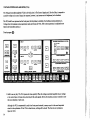
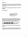
CONTOUR GENERATORS
As mentioned earlier, the voltage-controlled filter and the voltage-controlled amplifier are controlled by their
respective contour generators. The two contour generators function identically, and will output the same voltage
patterns if their controls are set identically.
That voltage pattern is a four-part contour that can be generically graphed as shown:
VOLTAGE
AMOUNT
TIME
KEY
RELEASED
36
1. Attack time: Time taken for voltage to increase from zero (initiated by trigger) to maximum.
2. Decay time: Time taken for voltage to decrease from maximum to sustain level.
3. Sustain level: A static voltage amount that, once initiated, continues as long as a key, or keys, is held down.
4. Release: Time taken for voltage to drop from sustain level to zero after the key is released.
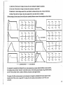
Different settings of these times and levels will produce markedly different contours. Some examples are shown below:
60
A
D
30
30
'V-
99
so
LOUDNESS CONTOUR
»
99
50
S
R
50
FILTER CONTOUR
It is important to remember that although the two contour generators can output radically different contour patterns,
the loudness contour will have "priority" over the filter contour. If the filter is going through a long, involved contour,
and the VCA has already closed, it makes no difference, because no audio signal is heard.
The output of the filter contour generator can be attenuated, or lessened, by adjusting the Contour Amount control
(described in the Filter section on page 32). The voltage from the loudness contour generator to the VCA is not
attenuated.
37
MODULATION (Low-Frequency Oscillator)
All the controllers mentioned up to this point have generated non-repetitive voltages; the keyboard generates a
static voltage level for each key, and the contour generators output a "one-shot" voltage pattern.
Musical sounds demand repetitive changes such as vibrato, trills, or tremolo. On The Source, repetitive changes are
controlled by a low-frequency oscillator
This oscillator generates waveforms exactly like the audio oscillators, but operates in a much lower frequency range
(1 cycle every 3 seconds to 30 cycles per second).
The output of this oscillator is a triangular or square waveform. This output voltage may be routed to the control
inputs of the oscillators and/or filter, through the Mod wheel.
Touch program H:
VOLTAGE CONTROLLED FICT
—I KB TRACK
ir I
I 16-I
m
FOOTAGE
SJMG
I
FILTER CONTOUR
32
K] [a]
I IE I
[ra
LOUONEB8 CONTOUR
WAVESHAPE
FOOTAGE
I INTERVAL
OSCILLATOR
■■■REC2-; •r.STOP
B^^BH ■ HIH
^^^^^H
CONTINUE vjj'PLAY 1
^^^^^B .\
^^^^^B
PLAY2^!rEC - "
'^^^^^" ..^^^^^M
FLAY
^^^^^^
■ -
A ^|
|
D
|
I
S
MODIFIERS
BANK
ARPEGGIO
S&H
SB H FtLTr AUTO TRIG
^^^^^M
■ ^^^^^* ■
.
PROGRAMS
38
| EMPHASIS |
FULL I
IMUL1
TRIQQER
1EC1
| CUTOFF |
EXT.TRIG
,
: SAVE
.-
VERK
\ .
t:».." ■
1. Hold down any key. Turn the Mod wheel up. A low-frequency triangular waveform is changing the
oscillator frequency, causing the pitch to move up and down. (The Mod Rate LED flashes at the
rate of the low-frequency oscillator).
2. Touch |i£||3
in the Mod section. Change the incremental control. The setting of the low-frequency
oscillator determines the rate of the pitch change.
3. Touch mi in the Mod section. The pattern of pitch change now has two distinct pitch levels, corresponding
to the upper and lower voltage levels of the square waveform.
The four lowermost switching controls in the Mod section are routing controls. The switches labeled TO OSC control
the routing of the modulation voltage to the oscillators; the switches labeled TO FILTER determine routing to the
filter.
Touch program Q:
VOLTAGE COIMTRDU_EO FILTER
KB TRACK
0
03 0 Hii
WAVESHAPE
INTEfiVAl
OSCILLATOB
BANK
39
Bfel
1. Hold down any key. Turn up the Mod wheel. Modulation to the oscillators produces a vibrato effect.
2. Switch modulation |t]gg|
to Osc and |2U|
to Filter. Modulation of the filter cutoff frequency is called
tremolo; it is a more subtle effect and will usually be hidden by vibrato.
3. Touch Ml and repeat steps 1 and 2. The square wave can also control the oscillators or filter.
The Source may be thought of as having two main operating sections — the analog synthesizer and the digital control
circuits. The analog functions have been described; the next section deals with the digital functions that send control
signals to the analog synthesizer.
40
DIGITAL FUNCTIONS
The microprocessor, in addition to storing programs, directs and controls all Level 2 functions. Some of the Level 2
functions, such as Auto Trig and Interface on-off, are basically "change-of-status" functions, and require little memory
The "recording" functions — the sequencer, the arpeggiator, and the program sequencer - require recording, not
only of status and voltage amounts, but of time values. This requires a time-measuring circuit, so the low-frequency
oscillator (LFO) is used as a clocking circuit. The resulting pitch and timing information is stored in memory, and
recalled when the appropriate "real-time" function is selected.
THE SEQUENCER
In the sequencer record mode, the microprocessor determines and stores trigger status and keyboard control voltage.
When the sequencer mode is activated, the LFO is unconditionally set at 67 Hz. This allows timing discrimination of
7.5 milliseconds (the duration of a note will never be off by more than 7.5 milliseconds).
The sequencer stores every change in trigger status and every change in keyboard voltage, whether or not they occur
simultaneously.
The following musical example:
will be stored in this manner.
(VOLTAGE LEVEL)
TIME
41
The absolute value of keyboard voltage is stored, so the setting of the octave transpose switch during recording will
determine the octave of sequence playback.
Note that when sequences are recorded, rests, or spaces between notes, are recorded as events, and take up one event
position each. To store the maximum number of actual notes in a sequence, follow this procedure:
1. When recording, play all notes in legato (smooth) style, lifting off the keys only when an actual rest is desired.
2. For playback, use a program set in the multiple trigger mode. This will retrigger the contour generators
whenever the keyboard voltage changes.
Normally, a retrigger would be accomplished during recording only by releasing all keys between notes. Following the
above procedure will prevent a loss of recording length that can run as high as 30%.
The longest time duration that can be held in one storage location is 30 seconds. If a note or rest exceeds 30 seconds,
it will merely take up two event positions, and playback will exactly duplicate the recording (no "glitches" or
retriggers).
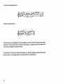
Note:
The sequencer will stop recording only when g|£2U| or another Level 2 control is touched. Since the
sequencer plays the sequence continuously, the duration of the final event is critical.
In this musical sequence ...
B)
... touching JSWia (or any other Level 2 function) at beat "A" would make the sequence three measures long.
To reproduce the example as written, the last key must be released at beat "A," and four beats of rest must be
counted silently before touching QQQ at beat "B."
In the playback mode, the sequencer output replaces the keyboard output, and the keyboard is "dead"; the
control voltage, octave transpose switches, and trigger are disconnected. Glide, however, can be applied to a
sequence during playback (having Glide on during recording makes no difference).
42
THE ARPEGGIATOR
The Arpeggiator will store up to twenty-four control voltage values and metronomically play them back at the LFO
rate. The first note recorded cannot be repeated during the arpeggio; replaying the first note shifts the arpeggiator
into the playback mode.
The arpeggiator records the keyboard control voltage present at the initiation of each new note; it does not record
timing information.
Note the musical pattern below:
B
(A)
The notes in section "A" may be played in at any tempo or rhythm. After playing the last note in "A," the
arpeggiator will still be in the record mode, waiting for new information. Playing note **B" (repeating the first
note played) at any point afterward immediately initiates repeated playback of the first eight notes. With this
technique, an arpeggio can be loaded into a kind of "holding" status, to be initiated on command.
Touching H«MI«flH W£iSIMJctdI#j. iia^I3^^9,
K^SZSMMImSIs
will play, from the beginning, tne last
arpeggio entered. Once playback is initiated, operational sequence is as described in Section L
The only limitation to note entry is that the first note cannot be repeated. All other notes or combinations of
notes are viable.
If a note is played several times in succession while loading the arpeggiator, it will be played back as one note
with the total duration of the successive notes played. This allows a limited timing discrimination to be recorded.
43
In other words, entering these notes:
i
results in this playback pattern:
This occurs because, in the arpeggiator record mode, triggers are stored only when the keyboard voltage changes.
Repetitions of the same note produce no keyboard voltage changes, so no triggers are stored. This feature can be
used to produce arpeggios with rhythmic variations.
As described in the first section of this manual, touching any key while the arpeggiator is playing instantly selects
the record mode, so a new arpeggio pattern may be entered without "breaking rhythm."
44
THE PROGRAM SEQUENCER
The program sequencer works in conjunction with the two sequencers and, in fact, stores its information in the
same general memory locations.
Each event of each sequence is stored in memory as a digital value. A portion of that digital value is reserved for
program sequence information. When the program sequencer playback is activated, it looks at the sequencer memory
for information. If no program sequencer information has been recorded, the program will not change.
A reliable procedure for recording program sequence information is as follows:
1. After recording a sequence, play it back very slowly. Rehearse the intended program changes.
2. When all the program changes have been decided, touch |j||^Sli&Ultsl3Slii3!^ • The sequencer will start
over from the beginning.
3. Don't try to synchronize note changes with program changes. Wait until the sequencer plays a note, then
make the program change. The program sequencer will remember the last program called during an event, so
if more than one change is made during a note (or rest), make sure the final program is the desired one.
4. When the program sequencer is in the record mode, the notes in the sequencer will be played only once. At
the end of one cycle, operation will revert to Level 1.
5. Note: Tf ■a:flct:riWiM»i:l3Bl is touched and no program changes are specified, all sequencer
events will be "loaded" with the program currently displayed.
Note, also, that entering a new sequence erases the previous program sequence changes. When a sequence is
entered, the program sequence information is set to a default value of program 1; i.e., if the program
sequencer playback is activated without previously recording some program changes, all events in the
sequencer will be played with program 1.
45
UNCONDITIONAL TUNING ("AUTO TUNE")
It is possible that, after warm-up and stabilization, the two audio oscillators in The Source may not be nominally
tuned to exact unison.
A procedure to correct this is described in Tuning Up, on page 3 . This procedure involves unconditional access
to oscillator 2 and should be explained further.
Simultaneously touching |8||t|2|g and |tggU Level connects the incremental control to the master tuning input
for Osc 2. Turning the incremental control will adjust the tuning of Osc 2, relative to Osc 1, without changing the
stored values for Osc 2 interval for each voice. The range of adjustment in this mode is approximately 1 semitone.
The factory programs are voiced with careful attention to the tuning of Osc 2. Osc 2 is generally tuned to some
consonant interval — an octave, a major tenth, etc. These interval values are set in memory on the assumption that
Osc 1 and Osc 2 are tuned as close to exact unison as possible.
A general tuning procedure is described in the Troubleshooting Section beginning on page 53.
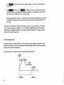
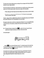
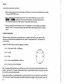
THE INCREMENTAL CONTROL
The incremental control is the most important single control on The Source. It controls the settings of all variable
parameters, and determines the rate of operation for most Level 2 functions. Its operation should be thoroughly
understood.
The incrementer is a freely-turning opto-electronic controller. An optical sensor notes a change from light to dark,
which is generated by passing spaced bars through the sensor (as shown in the figure below). There are 120 opaque
bars on the transparent incrementer, allowing 240 changes of status.
(LIGHT SOURCE/
LIGHT SENSOR MECHANISM)
46
Iliis system permits adjustable resolution. Relatively coarse controls, such as the mixer level controls, may go from
minimum to maximum in one complete turn. This means that 100 values (0 to 99) are controlled by 240 status
changes, resulting in a resolution of approximately 0.41%. In other words, 12 changes of status produce a change
of 5%.
On sensitive controls, such as Osc 2 frequency, minimum to maximum can take up to 16 complete turns, yielding a
resolution of 0.025%. In this mode, 192 changes of status are needed to produce a 5% change.
The circuitry in the incrementer can reliably track over 300 status changes per second — much faster than the knob
can normally be turned, so the incrementer always responds correctly to any movement.
"Spinning" the control knob is generally not recommended; if a second control is touched while the knob is moving
freely, the setting of that control may be inadvertently altered.
A unique advantage to the *'one-knob" approach appears in editing. If a control is accessed for editing, it comes up
at the value in memory and is smoothly adjusted up or down from that point. On other programmable systems, a
control becomes active when it is physically moved. If the physical position of that control is radically different
from the value in memory, a sudden "jump** occurs. The incremental controller overcomes this limitation and ensures
smooth, subtle editing changes under all conditions.
47
INTERFACING
The Source communicates with the outside world through its rear panel connections. The audio output has already
been discussed; without it, no signals can be heard. The remaining jacks send control signals to and from The Source.
Communication between electronic devices is called interfacing. The audio connection between The Source and an
amplifier is a very simple interface; more sophisticated interfaces will allow The Source to control, or be controlled
by, other synthesizers.
OUTPUTS
Control Voltage Out
The control voltage (CV) in/out is a dual function jack that sends and/or receives control voltages, depending on the
plug used.
When used as an output, the CV jack outputs all control voltages generated by The Source (except the two contour
generators). This includes the keyboard, LFO, pitch wheel, both sequences, arpeggiator, and sample and hold.
The voltage at the CV output is intentionally scaled high to allow for discrepancies in other synthesizers. The output
voltage may have to be run through a 10K linear potentiometer to achieve 1.00 volts/octave.
Trigger Out
Used as an output, the trigger in/out jack generates an S-Trig (switch trigger — a short to ground) when a trigger is
generated in The Source. This occurs when:
1. A new key is depressed in the multiple-trigger mode, or all keys are released and a new key (or keys) is
depressed in the single-trigger mode.
2. The sequencer generates a trigger.
3. The arpeggiator is running.
4. The Auto Trig is active.
5. The sample and hold is running.
Note: If the Level 2 [S3S3S (Pr°£ram 13) is set to OFF, all external triggers are defeated.
48
INPUTS
Control Voltage In
As an input, the CV jack sends any control voltage received to the oscillators and filter, which track this incoming
voltage at 1 volt/octave.
Any device that outputs a control voltage — a Moog 1120 Foot Pedal Controller, an external sequencer, or another
synthesizer's keyboard — may be used as a control input.
Trigger In
The Source's contour generators will be triggered whenever an S-trig (a shorting connection) appears at the input
portion of the Trig jack.
This S-trig may be generated by another synthesizer, synthesizer accessory, or a simple mechanical switch closure.
Such a closure must be opened and reclosed to generate any successive triggers.
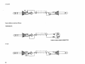
CABLES
To use the interface connections correctly, 3-conductor (stereo) plugs must be used. Input connections appear
at the ring; output connections are at the tip.
Output cables should be constructed as follows:
TRIGGER OUT:
TIP
FROM SOURCE
(MALE CINCH-JONES CONNECTOR)
NOTE:
Some other brands of synthesizers (and some newer Moog instruments) may not use the Cinch-Jones
connectors. Consult the instrument's owner's manual for proper procedure.
49
CV OUT:
TIP
Input cables are made as follows:
TRIGGER IN:
(FEMALE CINCH-JONES CONNECTOR)
CVIN:
50
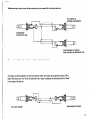
Simultaneous input/output control voltage connections can be accessed with a cable setup as shown:
(TO CV INPUT ON
EXTERNAL SYNTHESIZER)
a::"::::j(
(FROM SOURCE
INPUT/OUTPUT JACK)
a:::::::::
(FROM EXTERNAL CV SOURCE:
PEDAL CONTROLLER, SEQUENCER, ETC.)
The same cable could be used for simultaneous trigger input/output connections.
To interface two Sources together, two stereo (3-conductor) cables, wired ring-to-tip and ground-to-ground, will be
needed. The Source at the "tip" end of the cables will be the "master" synthesizer; the other Source will be "slaved"
to the outputs of the first unit.
4
(TO "SLAVE" SOURCE)
(FROM "MASTER" SOURCE)
51
As mentioned earlier, the Level 2 MEiMfflci control determines the presence or absence of triggers at the trigger
output. However, switching this control off does not defeat the control voltage output. If an external synthesizer is
connected, it will always be affected (transposed) by The Source's CV output.
To scale the CV output, follow this procedure:
1. Connect a 10K linear potentiometer in series between The Source's CV output and the second ("slave")
synthesizer's OSC or CV input.
2. Connect the appropriate trigger cable; turn the
l:»:«i;uci output on.
3. Turn down The Source's volume; alternately play The Source's low F and the F 2 octaves higher. Adjust the
potentiometer until the two pitches sounded by the slave synthesizer are in tune.
4. Turn up The Source. Play low F and tune the slave synthesizer to unison.
The slave synthesizer will be triggered by The Source and will follow The Source's keyboard, LFO, pitch wheel,
sample and hold, sequencer, and arpeggiator.
52
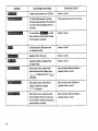
TROUBLESHOOTING
If a problem exists on The Source, check the symptoms listed below. If the solutions listed (or common sense) won't
correct the problems, the instrument should be taken to an authorized service center for examination and/or repair.
53
54
55
TUNING
A generalized tuning procedure is as follows:
1. Select a program using only Osc 1 as a signal source. Hold down any key and tune to the desired pitch source, using
the rear panel FINE TUNE control.
2. Select a program using both Oscillators that has Osc 2 set at a known interval (fifth, octave, etc.) Touch
MWa^ and PUflj^j simultaneously. This connects the incrementer to the master tuning control for
Osc 2. Adjust the incremental controller until Osc 2 is at precisely the known interval.
3. Touch any program. The interval settings for Osc 2 for each program have not been changed, so all programs
should be "in tune." If a new interval tuning (or beat rate) is desired, change the setting of the Osc 2 interval
control.
CASSETTE OPERATIONS
The Source outputs all pertinent data in a restorable format to a standard cassette recorder. Any cassette recorder
with remote microphone start/stop capabilities will work; a special "computer cassette deck" is not necessary (but
is recommended).
A standard 5-Pin DIN connector is used. Pin assignment is as follows:
1. Pin 1:
Relay (Motor On/Off - to REM jack).
2. Pin 2:
Ground
3. Pin 3:
Relay
4. Pin 4:
Data In (from EARPHONE or LINE out)
5. Pin 5:
Data Out (to AUX or LINE input)
Note: Recording and playback levels are quite different from ordinary audio recording. Recording levels should be 0 dB
or higher ("into the red" on VU meters). Smaller cassette decks, or computer cassette recorders, incorporate an automatic
level control that sets correct levels internally.
Playback levels should be set correspondingly higher. A good rule of thumb is to set the output level at between 60% and
75% of full volume. If cassette load operations continually fail (produce error messages), adjust the cassette output level.
56
As mentioned earlier, a high-quality leaderless cassette tape should be used. If the tape is to be reused, it must be
totally erased with a bulk eraser or demagnetizes Since, in the "verify" mode, each piece of data is counted and
compared to a master checksum, the presence of any additional or residual data will cause an error.
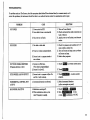
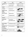
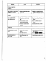
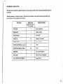
LEVEL 2 FUNCTIONS
The following is a quick reference chart for the functions of the Level 2 controls. All controls in this chart are
activated by touching the Level 2 control first.
Some of the controls activate a temporary function that ends when certain.conditions have been satisfied; i. e.,
touching 03233313 activates the arpeggiator record mode until 24 notes have been entered, at which time the
instrument's status changes. These temporary conditions are listed in STATUS WHEN ACTIVATED; eventual
status is listed under CONTINUAL STATUS.
CONTROL
STATUS WHEN ACTIVATED
CONTINUAL STATUS
Level 2 Seq Record Mode; sequence
Level 2 until raPM or another Level 2
begins recording with first note depressed,
control is touched-
Defeats
Immediately reverts to Level 1.
ARPEGGIO
CONTINUE
Continues Sequencer playback from
Immediate Level 1.
stopping point. After fjiziaattwi.
starts from beginning of last arpeggio
played.
Immediate Level 1 (with Sequencer playback).
PLAY 1
Starts Sequencer playback from
PLAY 2
beginning.
ARPEGGIO
Activates Arpeggiator. If key is
Arpeggiator is active; Level 1 (programs may
depressed, Arpeggiator shifts to record
be chosen).
mode. If ggimmm<jg is touched,
Arpeggiator plays back.
57
58
INCREMENTAL RESOLUTION
This chart shows the different resolutions present on the incremental controller when incremental (adjustable) functions
are selected.
Generally speaking, if a function is critical, it will have very fine resolution. Less critical functions will generally need
only one turn to cover all ranges of that function.
59
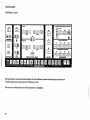
SOUND CHARTS
PROGRAM 1: LEAD 1
VOLTAGE CONTROLLED FILTER
HKB TRACK
H El
16
H 0 IM
FOOTAGE
56
56
WAVESHAFE
SYNC
FILTER CONTOUR
69
10H
0
STORE
■■-■■. REC1
REC 2 :::tj"-:: STOP
OSCILLATOR
CONTINUE ,Jf JPLAY 1
PLAY 2
SANK
77
99
MODIFIERS
S&H
S& H FILT 'AUTO TRIG
EXT.THIG
: SAVE
PROGRAMS
The high settings of the mixer controls (maximum for both oscillators) overdrive the filter input and produce the
controlled distortion that characterizes the "Minimoog Sound.*'
This voice is very effective when used with the sequencer or arpeggiator.
60
68
LOUDNESB CONTOUR
WAVESHAPE
MEMORY
68
80
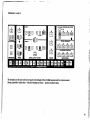
PROGRAM 2: LEAD 2
CONTROLLEO FILTER
KB TRACK
26
73
27
FILTER CCMVTOUR
65
42
The foundation of this voice is the use of square waves through a filter with high resonance and low contour amount.
Playing "guitar-like" melody lines — with pitch-bending and vibrato — produces excellent results.
61
PROGRAM 3: HORN
Full keyboard tracking gives this voice a tuba-like quality in the lower octaves and a brighter, trumpet-like quality
in the higher registers. Vibrato is available at the modulation wheel.
62
PROGRAM 4: FLUTE
VOLTAGE COIMTROU-ED FILTER
KB TRACK
30
0
0
CUTOFF I I EMPHASIS
This program uses a small amount of noise to simulate the sound of air blowing over a flute mouthpiece.
Tremolo is available at the modulation wheel and should be used for most authentic results.
63
PROGRAM 5: CLAV BASS
VOLTAGE CONTROLLED RLTER
KB TRACK
2
4
80
EMPHASIS
0
■it
67
A ^J
| '
11
D
LOUDNEBB CONTOUR
Narrow rectangular waveshapes simulate the sound of a plucked string. A high contour amount setting gives this program
a very bright sound. Pitch-bending is effective with this voice.
64
PROGRAM 6: VIBES
CONTROLLED FILTER
KB TRACK
10
20
40
LOUOIME8S COfSfTOUP
Turn the mod wheel up to approximately 75% for tremolo. Note the settings of the contour generators.
If a key is depressed and held down, the contour generators reach the sustain level (zero) and stop all sound,
producing a "damped" sound. If a key is tapped and released quickly, the contours "skip" the sustain setting
and move immediately to the long release time, producing a "ringing" vibes sound.
65
PROGRAM 7: STRING BASS
VOLTAGE CONTROLLED FILTER
K8 TRACK
18
0
26
CONTOUR
FILTER CONTOUR
0
OUDNE88 CONTOUP
0
65
o
OSCILLATOR
BANK
0
|
|
s
MODIFIERS
This voice sounds best toward the bottom of the keyboard. This program is voiced with the same touch-dependent
iif
effect described in program 6, so certain notes may be allowed to "ring" longer than others.
!;■♦•'
66
81
PROGRAM 8: HARPSICHORD
CONTROLLED FILTER
KB TRACK
74
0
21
EMPHASIS
LOUDNE8B CONTOUR
0
69
0
43
This voice pitches the second oscillator an octave higher to simulate the octave strings of full harpsichord stops.
For an "absolutely in tune" harpsichord sound, touch SYNC ON. Leaving sync off, however, may produce
a more authentic sound.
67
PROGRAM 9: ORGAN
VOLTAGE CONTROLLED FILTER
KB TRACK
26
0
The percussive attack of the filter contour will be heard only after all keys have been released and a new key (or keys)
has been played. This enables particular notes within a phrase to be accented.
68
PROGRAM 10: TRILL VOICE
VOLTAGE CONTROLLED FILTER
K8 TRACK
13
This program is one of several voiced to sound "electronic" — unlike any traditional instrument. The modulation
wheel will set the upper note of a trill. Sync is voiced ON; move the pitch wheel to hear the sync effect.
69
PROGRAM 11: TAURUS
VOLTAGE CONTROOEO FILTER
KB TRACK
1/2
I
21
0
I CUTOFF I
I EMPHASIS
One of the keys to the power of this voice is the tuning of Osc 2. If the tuning procedure listed in the Troubleshooting
Section is followed correctly, the two oscillators should be detuned just enough to produce a rich, rolling sound.
70
70
PROGRAM 12: SYNTHEVOX
Another "electronic" voice — especially good for long, singing solo lines. The oscillators are tuned an octave apart
and long attack times are set up on both contour generators.
71
PROGRAM 13: SAX
AQE CONTROLLED FILTER
'
OSCILLATOR
REC2.V.i,&STDP
CONTlNUi
^
8
MODIFIER]
,\Oi>r
S&H
S& HfrLT.-AUTC
tti
. SAVt
VtRlhV
LOAD
,
PROGRAMS
The use of narrow rectangular waveforms as audio signals gives this program the high resonance present in the sound
of an alto or soprano saxophone. This voice sounds more realistic when pitch-bending and modulation are used.
72
B3
PROGRAM 14: WIND
VOLTAGE CONTROLLED FILTER
KB TRACK
18
1/2
I
I CUTOFF I
80
0
I EMPHASIS
LOUDNEBB CONTOUR
Noise is the audio signal here. Emphasis is set high to give the noise signal a "pitch" (by sharply accenting
a narrow band of frequencies). The filter may be slowly moved up and down (by raising the modulation wheel)
to simulate a "sweeping" wind sound.
73
PROGRAM 15: SNARE DRUM
VOLTAGE CONTROLLED FILTER
KB TRACK
52
0
LOUDNE88 CONTOUR
A high-level noise signal is mixed with a low-level triangle wave to give the sudden drum sound a sense of pitch.
The pitch, or tuning, of the drum is determined by the key played. Setting LFO rate to between 65 and 70 and
turning on AUTO TRIG will produce a drum roll.
PROGRAM 16: DUPLICATION OF PROGRAM 1
Program 16 may be used to store a personal program without erasing the factory programs or can be used
to rearrange programs (see Repositioning Programs, page 12).
74
37
INDEX
Amplification
Arpeggiator
Loading
Playback
Rhythmic Arpeggios
Attack Time
Auto Trig
Auto-Tune
Cassette Operations
Loading
Saving
Verifying
Connectors
Recording Level
Types of Data Stored
Contour Generators
Defined
Filter Contour
Loudness Contour
Controllers
Decay Time
Display
Program
Incremental
Editing Programs
Ext Trig
Factory Programs
Charts
Filter
Cutoff Frequency
Emphasis
KB Track
Contour Amount
2
17,43
17
18
44
36
23
3,46, 56
21, 56
22
21
22
56
56
21
36
36
32, 37
34,37
35
37
2,8
2
8
7
24
5
60-75
30
30
31
33
32
Fine Tune Control
Frequency
Oscillator
Cutoff
Glide
Hold Control
.- - -
3
26
26
30
35
12
Incremental Controller
Diagram
Resolution Table
46
46
59
Interfacing
Procedure
48
52
Control Voltage
Triggers
Scaling
Cables
Interval
KB Track
Keyboard
As Controller
LED
48,49
48,49
52
49-51
27
33
35
35
Priority
Triggering
Voltage
Glide
36
36
35
35
8v
Level 1
Level 2
Definition
Function Table
LFO
Used with Sequencer
Used with Arpeggiator
Used with Sample & Hold
As Modulation Source
4V
•
15
15
57
38
16, 41
18
24
38
75
Maintenance
1
Microprocessor
Mixer
Sample & Hold
TO OSC
TO FILT
15
8-9
23-24
23
24
30
38
Sawtooth Waveshape
Defined
38
Operation
LFO
38
Playback
15
Routing
39
Recording
16
6
26
Efficient Loading
42
Setup
Multiple Triggering
36
Signal Sources
26
Noise
29
Single Triggering
36
Square Waveshape
28
Modifiers
Modulation
Wheel
Modules
Octave Switches
6
Oscillator
Octaves
Tuning
11
Sustain Level
37
6
19,45
Loading
19-20
Cancelling
,
Programs
Factory
2
Store Control
Program Sequencer
Activation
15
26
27-28
Pitch Wheel
15,41
27
2, 27
Waveshapes
Sequencer
28
Switching Functions
7-8
Sync
28
Touch Panel
2,7
Tremolo
40
Triangular Waveshape
28
20
Trigger
36
58
Troubleshooting
53
14
Tuning
14
Oscillators
3
3,27
Playing
4
Interval
27
Editing
7
Filter
30
Storing
11
Rate LFO
39
Repositioning
12
VCA (Voltage Controlled Amplifier)
34
Rectangular Waveshape
28
Vibrato
40
Release Time
37
Voltage Control
Resolution
59
Reviewing Programs
9
Volume
Waveshape
A comprehensive Service Manual is available (Moog P/N 993-045393-001). Contact your local dealer or write to:
MOOG MUSIC INC., 2500 Walden Avenue, Buffalo, New York 14225, Attn: Service Department
76
26, 32, 34, 35
6
27-28
GENERAL INFORMATION
Under normal playing conditions, the rear panel of The Source will feel quite warm to the touch. This is not a malfunction;
The Source's internal components are calibrated to operate correctly at this temperature.
The Source is a software-based instrument. As new developments are completed, additions to the Owner's Manual
will consist of drop-in sheets stating a revision number and a description of the software function changes.
Additional cassette files with voices created by prominent keyboard artists and consultants to Moog may be purchased by writing:
Moog Music Inc.
2500 Walden Avenue
Buffalo, New York 14225
Attn: Marketing Department
Permission is given to reproduce the sound chart below for non-commercial purposes.
AGE CONTROLLED FILTER
KB TRACK
77
MOOG MUSIC INC.
2500 Walden Avenue
Buffalo, New York 14225
993-045352-001
Copyright 1981 Moog Music -nc.
Printed in U.S.A.-TG-3500