1
VENTED GAS LOG SET
INSTALLATION AND OPERATING INSTRUCTIONS
MODELS
VWF18N VWF24N VWF30N VWF36
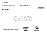
WARNINGS
If the information in this manual is not followed exactly,
a fire or explosion may result causing property damage,
personal injury or loss of life.
®
This gas log set is to be installed
only in a solid-fuel burning fireplace
with a working flue constructed of
noncombustible material.
–
Do not store or use gasoline or other flammable
vapors and liquids in the vicinity of this or any
other appliance.
–
WHAT TO DO IF YOU SMELL GAS
• Do not try to light any appliance.
• Do not touch any electrical switch; do not use any
phone in your building.
• Immediately call your gas supplier from a
neighbor's phone. Follow the gas supplier's
instructions.
• If you cannot reach your gas supplier, call the
fire department.
–
Installation and service must be performed by
a qualified installer, service agency or the gas
supplier.
READ AND SAVE THESE INSTRUCTIONS
CONTENTS
Important Safety Information ......................... 3
Product Specifications .................................... 4
Minimum Hearth Dimensions ........................ 4
Getting Started ................................................. 5
Burner - Grate Assembly 18", 24", 30", 36"... 5
18", 24", 30", 36" Ceramic Fiber or
Refractory Logs ............................................. 5
Items for Installation ...................................... 5
Minimum Free Opening Area of
Chimney Damper for Venting ........................ 5
Minimum chimney Height and Flue Opening 5
Placement in a Fireplace with a Restrictive
Barrier ......................................................... 6
Installation ........................................................ 7
Installation for Gas Valve Kits ........................ 8
Supplemental Instructions for SPL-NG/SPLLP .................................................................. 8
Supplemental Instructions for MANVK ........ 10
Supplemental Instructions for MVVKLP ...... 10
Supplemental Instructions for MVVKN ........ 10
Supplemental Instructions for MXVKLP ...... 11
Supplemental Instructions for MXVKN ........ 11
Operating Instructions for SPK kits.............. 22
For Your Safety Read Before Lighting ........ 22
Manual Control (SPK) Lighting Instructions 22
Milli-Volt Control Lighting Instructions ........ 23
Operating Instructions for Manual Control
(Without Pilot).............................................. 24
Flame Appearance .......................................... 25
Checking Burner Flames ............................ 25
Pilot Flame Appearance .............................. 25
Fireplace Draft Test ....................................... 26
Remote Control Receiver Replacement ..... 27
Cleaning and Servicing ................................. 27
Replacement Parts ......................................... 28
Assembly..................................................... 28
Massive Oak Logs ...................................... 29
American Oak Logs .................................... 30
Birch Logs ................................................... 30
Split River Oak Logs ................................... 31
Split Pine Logs ............................................ 32
Warranty .......................................... Back Cover
Wiring (Milli-volt) ............................................ 12
Connecting the Gas ....................................... 13
Log Placement ............................................... 14
Filling Front Buner Pan ............................... 14
Placement of Glowing Embers (Rock Wool)14
Placement of Decorative Volcanic Rock ..... 14
VWF18MO Log Placement ......................... 14
VWF24MO Log Placement ......................... 15
VWF30MO Log Placement ......................... 15
VWF36MO Log Placement ......................... 16
VWF18AO/24AO/36AO Log Placement ..... 17
VWD24B Log Placement .. 18VWF24/18SRO,
30/24SRO, 36/30SRO ................................ 19
VWF18SPA/24SPA Log Placement ........... 20
VWF30SPA Log Placement ........................ 21
2
27D7300
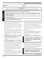
IMPORTANT SAFETY INFORMATION
INSTALLER
Please leave these instructions with the owner.
OWNER
Please retain these instructions for future reference.
IMPORTANT
• Any change to this gas log or its controls can be dangerous.
• Improper installation or use of the gas log, such as operating with glass doors
closed, can cause serious injury or death from fire, burns, explosion or carbon
monoxide poisoning.
• Do not allow fans to blow directly into the fireplace. Avoid any drafts that alter
burner flame patterns.
• Do not use a blower insert, heat exchanger insert or other accessory, not approved for
use with this heater where applicable.
The installation, combustion and ventilation air must conform with local codes or, in the absence of local codes,
with the National Fuel Gas Code, ANSI Z223.1.
2. Installation and repair should be done by a qualified
service person. Monessen Vented Gas Logs must be
installed only in a masonry or a UL 127 solid-fuel fireplace with minimum venting requirements, see installation section.
3. To prevent malfunction, gas log set and flue should be
cleaned at least annually by a professional service person.
More frequent cleaning may be required due to excessive lint from carpeting, etc. It is imperative that control
compartments, burners and circulating air passageways
be kept clean.
4. A damper clamp must be installed to provide the
minimum permanent vent opening to vent flue products, Refer to installation instructions.
5. Never burn solid fuels in a fireplace where a gas log set
is installed.
6. This appliance must NOT be used with glass
doors in the closed position. A fireplace screen
must be in place when the log set is burning. Provisions
for adequate combustion air must be provided. Adequate
combustion air usually results in all flames curling into
the fireplace away from screen and up the flue.
8. Keep room area clear and free from combustible materials, gasoline and other flammable vapors and liquids.
9. Children and adults should be alerted to the hazard of
high surface temperature and should stay away to avoid
burns or clothing ignition.
10. Young children should be carefully supervised when they
are in the same room with the gas log set in operation.
11. Do not place clothing or other flammable material near
the fireplace when the gas logs are in use.
27D7300
12. Do not use this gas log set if any part has been underwater.
Immediately call a qualified service technician to inspect
the gas logs and replace any part of the control system
and any gas control which has been under water.
13. The gas log set must be isolated from the gas supply
piping system by closing its individual manual shutoff
valve during any pressure testing of the gas supply
piping system at test pressures equal to or less than 1/2
psig (3.5kPa).
14. Secure gas log set to fireplace.
15. This log set will burn off the paint on the front grate bar.
Note: See cleaning section for refurbishing.
16. L P s e t s m u s t b e i n s t a l l e d w i t h S P K - L P o r
MVVKLP kits.
17. FOR MASSACHUSETTS RESIDENTS ONLY:
WARNING
1.
This product must be installed by a
licensed plumber of gas fitter when
installed within the Commonwealth of
Massachusetts.
Installation of this vented gas log in the Commonwealth
of Massachusetts requires the damper be permanently
removed or welded in the full open position. In addition, a
naturally vented gas log may not be installed in a bedroom
or bathroom in the Commonwealth of Massachusetts.
Flex line installation must not exceed 36".
WARNING
WARNING
Read these instructions carefully before installing or trying to operate this vent-free gas heater.
This appliance is for installation only in
a solid fuel burning fireplace (masonry
fireplace or manufactured fireplace)
Continued on page 4
3
We suggest that our gas hearth
products be installed and
serviced by professionals who
are certified in the U.S. by the
National Fireplace Institute®
(NFI) as Gas Specialists.
WARNING
SAFETY INFORMATION
Never connect unit to private
(non-utility) gas wells. This
gas is commonly known as
wellhead gas.
www.nficertified.org
PRODUCT SPECIFICATIONS
Model
VWF18N
VWF24N
VWF30N
VWF36N
A
18"
24"
30"
36"
B
C
D
1
12" 12 /2" 161/2"
12" 14" 20"
11" 18" 26"
12" 20" 28"
MINIMUM HEARTH DIMENSIONS
Model
VWF18N
VWF24N
VWF30N
VWF36N
A
17"
23"
24"
36"
B
13"
13"
13"
13"
C
20"
26"
32"
34"
D
A
C
B
For SPK Kits add 4" to C and A Dimensions
For MVVK and MXVK Kit add 8" to C and A Dimensions
The minimum inlet gas supply pressure is 4" for natural and 10" for
LP.
The maximum inlet gas supply pressure for this log set is 10" for natural
and 13" for LP.
Nominal Rates (BTU/Hr)
VWF18N
VWF24N
80,000
90,000
Figure 2 - Minimum Hearth Dimensions
VWF30N 90,000
VWF36N 90,000
Note: Actual performance, flame height, BTU/Hr will vary with specific installation, gas pressure,
shutoff valve position (fully open), valve type, and firebox draft conditions.
4
27D7300
GETTING STARTED
MAKE SURE YOU HAVE RECEIVED ALL PARTS
Check your packing list to verify that all listed parts have been received. You should have the following:
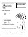
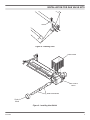
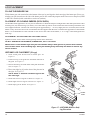
BURNER - GRATE ASSEMBLY 18", 24", 30", 36"
• Burner and Grate Weldment Assembly
• Lava Rocks (x2)
• Reducer
• Glowing Embers (Rock Wool)
• Damper Clamp
• Injector
• Installation /Operating Instructions
• Vermiculite
•
3/8" Aluminum
Tube with 3/8"
90° Elbow, 1/2" to 3/8" tube fitting
• Shield Plate
WARNING
18", 24", 30" OR 36" CERAMIC FIBER OR REFRACTORY LOGS
• Individual Logs
• Installation Instructions
• Handle the gas log burner assembly by the grate only. Do not pick the unit up
by the burner.
• Gloves are recommended when handling ceramic fiber logs to prevent skin irritation
from loose fibers. Logs are fragile — handle with care.
Carefully inspect the contents for shipping damage. If any parts are missing or damaged, immediately inform the
dealer from whom you purchased the appliance. Do not attempt to install any part of the appliance unless you
have all parts in good condition.
ITEMS REQUIRED FOR INSTALLATION
Ensure that the following items are available before proceeding with installation:
• External regulator (for propane/L.P.G. only)
• Shutoff valve
• Pipe wrench
• Piping which complies with local codes
• Drill with masonry bit (for mounting to the floor)
• Pipe sealant approved for use with propane/L.P.G. (Resistant to sulfur compounds)
WARNING
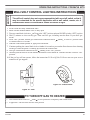
MINIMUM FREE OPENING AREA OF CHIMNEY DAMPER FOR VENTING
The fireplace and gas logs function as a system. If the fireplace is not drafting properly
and spilling into the room (check with a match or a smoke stick), reposition the damper
clamp until the positive draft is obtained by opening the damper. If negative pressure
in home prevents having a positive draft, contact your dealer for assistance.
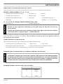
MINIMUM CHIMNEY HEIGHT AND FLUE OPENING
Chimney Height
6'
8'
10'
15'
20'
30'
27D7300
Flue Opening
64 sq in
64 sq in
64 sq in
51 sq in
51 sq in
51sq in
5
PLACEMENT IN A FIREPLACE WITH A RESTRICTIVE BARRIER
IMPORTANT INFORMATION FOR THE INSTALLATION OF THIS GAS LOG SET
The following are guidelines for placing a VWF log set with SPK, MVVK, or MXVK kit in a fireplace that has a restrictive barrier along the bottom front opening of the fireplace. Some examples of barriers are glass/screen door frames and
sunken/recessed fireplaces.
Height of Restriction (X)
Minimum Depth of Fireplace/Firebox
No restriction
13" - SPK Manual Control)
131/2" - MVVK (Milli-Volt Control) and MXVK (Hi/Lo Control)
0 to 1.5"
15"
Greater than 11/2" to 3"
15"
Greater than 3:
Any barrier greater than three inches (3") placed in front of the gas log set is not
recommended by the manufacturer.
Glass door frames
with adjustable
louvers should have
the lovers fully open
while the unit is in
operation.
The log set should be
placed against or as near
as possible to the rear wall
of the fireplace/firebox.
Height of restrictive barrier X
caused by glass door frames,
recessed fireplaces, etc. from
the base or bottom surface of the
unit. (See Table).
Depth of fireplace/firebox.
(See Table).
Barriers such as the bottom of a glass door frame placed in front of a gas log set can
change the air flow characteristics of the fireplace which in turn can cause the unit to
overheat and malfunction. Any deviation from the installation guidelines on this sheet
will potentially void the warranty.
NOTE: Non combustible material such as
refractory brick may be used to line the floor of
the fireplace in order to raise the height of the gas
log set in relation to a restrictive barrier.
6
CAUTION
WARNING
Figure 3
If the fireplace has a restrictive barrier
and is equipped with a remote receiver,
it must be placed outside. See “Remote
Control Receiver Replacement”on
page 25.
27D7300
INSTALLATION
INSTALL AND OPERATE THE APPLIANCE AS DIRECTED IN THIS MANUAL.
DAMPER STOP INSTALLATION
4 of the fireplace damper blade and provide a minimum flue opening, per table on page 5.
Should the clamp not fit, or provide the required permanent opening from the table, have the damper cut to provide a
minimum permanent opening or install a permanent stop.
Damper Stop
Damper
FOR MASSACHUSETTS RESIDENTS ONLY:
Installation of this vented gas log in the Commonwealth
of Massachusetts requires the damper be permanently
removed or welded in the full open position. In addition, a naturally vented gas log may not be installed
in a bedroom or bathroom in the commonwealth of
Massachusetts.
Figure 4 - Damper Stop Installation
BEFORE INSTALLING THE APPLIANCE
• Turn off gas supply to fireplace or firebox.
• Clean fireplace floor and chimney before installing log set. Seal any ash. Clean out doors to protect the unit
from down drafts.
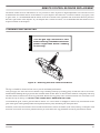
ASSEMBLY PROCEDURE
1. Place grate/burner assembly into firebox with the front pan facing forward.
2. Drill two (2) 5/32" diameter holes approximately 11/2" deep.
3. Anchor the front pan to the floor using the screws provided.
Proper installation of the grate is essential to prevent any movement of the gas logs and controls
during operation.
Injector
(Natural Gas
Only)
Screws
Figure 5 - Securing Grate/Burner Assembly into Firebox
27D7300
7
WARNING
INSTALLATION FOR GAS VALVE KITS
LP sets must be installed with a SPK
or MVVKLP Kit which includes the air
mixing nut and vermiculite. The natural
gas orifice must be removed.
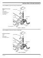
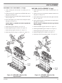
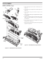
SUPPLEMENTAL INSTRUCTIONS FOR SPK-NG/SPK-LP
Burner Fitting
Adjust pilot flame to
cover thermocouple
Natural Gas Injector
Reducer
Pipe Nipple
SPK-NG Kit Includes
Valve
Pilot (Configured for NG)
Pipe Nipple
Heat Shield
Knob Extenders
Gas Control
Valve
Figure 6 - Connecting Valve to Unit (Natural Gas only)
Burner Fitting
LP Air-Mixing
Injector
SPK-LP Kit Includes
Valve
Pilot (Configured for LP)
Air Mixing Nut
Brass Nut
Heat Shield
Knob Extenders
Brass Nut
Gas Control
Valve
Figure 7 - Connecting Valve to Unit (LP only)
The Safety Pilot Kit attaches to the burner pan as shown above.
Use soapy water when checking all fittings for leaks.
8
27D7300
INSTALLATION FOR GAS VALVE KITS
Screw
Figure 8 - Installing Pilot
Heat Shield
Gas Control
Valve
Knob Extensions
Control
Knob
Figure 9 - Installing Heat Shield
27D7300
9
INSTALLATION FOR GAS VALVE KITS
WARNING
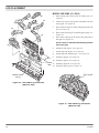
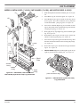
SUPPLEMENTAL INSTRUCTIONS
FOR MANVK
MANVK Kit Includes
Valve
Knob Extenders
Control Knob
The MANVK kit is
for Natural Gas
Only
Injector
Reducer
Valve
Control Knob
Knob Extenders
Figure 10 - MANVK
SUPPLEMENTAL INSTRUCTIONS
FOR MVVKLP
SUPPLEMENTAL INSTRUCTIONS
FOR MVVKN
MVVKLP Kit Includes
Valve
Pilot
Heat Shield
Cast Iron Elbow
Air Mixing Injector
Vermiculite
Brass Nut
MVVKN Kit Includes
Valve
Pilot
Heat Shield
Brass Elbow
Cast Iron Elbox
Pipe Nipple
Heat Shield
Heat Shield
LP AirMixing
Injector
Reducer
Pipe
Nipple
Brass Nut
Burner Fitting
90° Cast
Iron Elbow Burner Fitting
Brass 90°
Elbow
Injector
Gas Control
Valve
90° Cast Iron
Elbow
Figure 11 - MVVKLP
10
Gas Control
Valve
90° Cast Iron
Elbow
Figure 12 - MVVKN
27D7300
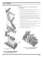
INSTALLATION FOR GAS VALVE KITS
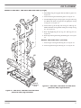
SUPPLEMENTAL INSTRUCTIONS FOR MXVKLP
MXVKLP Kit Includes
Valve
Pilot
Heat Shield
Elbow/Nipple Pipe
Air Mixing Nut
Vermiculite
Heat Shield
Flex Hoses
Gas Control
Valve
Air Mixing Nut
Figure 13 - MXVKLP
SUPPLEMENTAL INSTRUCTIONS FOR MXVKN
MXVKN Kit Includes
Valve
Pilot
Heat Shield
Elbow/Nipple Pipe
Heat Shield
Flex Hoses
Gas Control
Valve
Figure 14 - MXVKM
27D7300
11
WARNING
WARNING
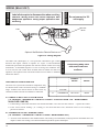
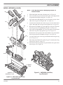
WIRING (MILLI-VOLT)
Label all wires prior to disconnection when servicing
controls. Wiring errors can cause improper and
dangerous operation. Verify proper operation after
servicing
Do not connect to 110
volt supply.
THTP
Pilot
TP
Milli-volt
Valve
TH
Optional Wall Switch or Remote Reciever
The Milli-Volt (thermopile) is a self powered combination gas control
that does not require 110VAC to operate. See Figure 12 and installation
instructions provided with optional wall switch or remote control for wiring
instructions. A maximum length of 15 feet of 18awg two conductor wire
is to be used for wall switch. Note switches must be suitable for milli-volt
operation. The optional wall switch and remote receiver must be mounted
outside the firebox.
CHECKING SYSTEM OPERATION
The milli-volt system and individual components may
be checked with a milli-volt meter having a 0-1000MV
range. Conduct each check shown in chart below by
connection meter test leads to terminals as indicated.
WARNING
Figure 15 - Wiring Diagram
Keep wiring away from
heat source and hot
surfaces.
CONNECT
METER
LEADS TO
TERMINALS
METER
READING
SHOULD BE
CHECK
TEST
TO
TEST
A
COMPLETE
SYSTEM
TH & THTP
CLOSED
B
THERMOPILE
OUTPUT
TH & THTP
OPEN
A. COMPLETE MILLI-VOLT SYSTEM CHECK
("A" READING - THERMOSTAT CONTACTS CLOSED - CONTROL KNOB "ON" - MAIN BURNER
SHOULD BE COME ON)
a. If the reading is more than 100 milli-volts and the automatic valve still does not come on — replace the control.
b. If the closed circuit reading (“A” reading) is less than 100 milli-volts, determine cause for low reading —
proceed as follows:
B. THERMOPILE OUTPUT READING CHECK
(“B” READING - THERMOSTAT CONTACTS OPEN - MAIN BURNER OFF)
a. 325 milli-volts minimum. If the minimum milli-volt reading is not obtainable, readjust pilot for maximum milli-volt
output. If milli-volt reading is still below minimum specified, replace thermopile.
12
27D7300
NOTICE: A qualified gas appliance installer must connect the
appliance to the gas supply. Consult all local codes before
installation.
Use new black iron pipe, steel pipe, copper tubing, or internally tinned copper tubing.
Copper or internally tinned copper tubing can only according to the National Fuel
Gas Code, section 2.6.3, providing gas meets sulfide limits, and where permitted by
local codes. Gas piping system must be sized to provide minimum inlet pressure
at the maximum flow rate (BTU/Hr). Undue pressure loss will occur if the pipe is
too small.
A manual shutoff valve must be installed upstream of the appliance. Union tee and
plugged 1/8" NPT pressure tapping point should be installed upstream of the appliance.
See Figure 16.
Pipe Coupling
To Gas Log
Set or to Gas
Valve
Gas Supply Inlet
Shutoff
Valve
WARNING
CAUTION
NOTICE
CONNECTING THE GAS
Connecting directly to
an unregulated propane/
LPG tank can cause an
explosion.
Pipe
Locations that the Pressure Tapping
Point May be Installed
Figure 16- Gas Connection
IMPORTANT: Hold appliance firmly with a wrench to prevent movement when connecting to inlet piping.
Always use an external regulator for all propane/LPG gas logs only, to reduce the supply tank pressure to a
maximum of 13" w.c.
27D7300
13
LOG PLACEMENT
FILLING THE BURNER PAN
Fill the burner pan with vermiculite to the bottom of the rear log and sloped to the front edge of the burner pan. Excess vermiculite can spill forward or to the side of the burner pan. Do not overfill the propane model. Do not cover the pilot (if SPK
or MVVK is installed) with vermiculite or rock wool (embers).
PLACEMENT OF GLOWING EMBERS (ROCK WOOL)
The Wildfire flame appearance can vary due to differences in draft and fireplace configurations and ember placement. After
installing rear (#1) and front logs (#2 and #3), cover the entire top surface of the vermiculite in the burner pan with the rock
wool supplied with unit. Tear the rock wool into pieces approximately 1/2" in size (roughly the size of a nickel) and cover the
burner evenly. Do no use more rock wool than the amount supplied with the unit. To enhance the appearance of the Wildfire
flame, it is recommended to form a mound of rock wool in the center of the burner, 2" to 3" high, visible through the two
front logs.
PLACEMENT OF DECORATIVE VOLCANIC ROCK
Sprinkle volcanic rock in front of front glowing embers and to both sides.
DO NOT SPRINKLE ON BURNERS, EMBER BED, PILOT OR LOGS.
IMPORTANT: Do not handle logs with your bare hands! Always wear gloves to prevent skin irritation
from ceramic fibers. After handling logs, wash your hands gently with soap and water to remove any
traces of fibers.
#6
VWF18MO LOG PLACEMENT (6 Logs)
1. Slide shield plate down back of burner pan. See
Figure 17.
2. Center rear log #1 on grate bars and flush with rear of
the grate. See Figure 17.
#4
#5
3. Place front left log #2 on the front of the plate and to the
left. See Figure 17.
#1
4. Place front right log #3 on the front of the plate and to
the right. See Figure 17.
NOTE: Allow 2" between the back log and the
two front logs.
5. Install left crossover log #4 as shown. See Figure 17.
#2
#3
6. Install right crossover log #5 as shown. See Figure 17.
7. Install top log #6 as shown. See Figure 17.
2"
Shield
Plate
Figure 17 - VWF18MO (Massive Oak)
Log Placement
14
27D7300
LOG PLACEMENT
VWF24MO LOG PLACEMENT (7 Logs)
VWF30MO LOG PLACEMENT (8 Logs)
1. Slide shield plate down back of burner pan. See
Figure 18.
2. Center rear log #1 on grate bars and flush with rear of
the grate. See Figure 18.
3. Place front left log #2 on the front of the plate and to the
left. See Figure 18.
4. Place front right log #3 on the front of the plate and to
the right. See Figure 18.
NOTE: Allow 2" between the back log and the
two front logs.
5. Install left log #4 as shown. See Figure 18.
1. Slide shield plate down back of burner pan. See
Figure 19.
2. Center rear log #1 on grate bars and flush with rear of
the grate. See Figure 19.
3. Place front left log #2 on the front of the plate and to the
left. See Figure 19
4. Place front right log #3 on the front of the plate and to
the right. See Figure 19
NOTE: Allow 2" between the back log and the
two front logs.
5. Install left middle log #4 as shown. See Figure 19
6. Install right top log #5 as shown. See Figure 18.
6. Install right middle log #5 as shown. See Figure 19
7. Install left top log #6 as shown. See Figure 18.
8. Install top crossover log #7 as shown. See Figure 18.
#7
7. Install right top log #6 as shown. See Figure 19
8. Install left top log #7 as shown. See Figure 19
9. Install top crossover log #8 as shown. See Figure 19
#6
#8
#6
#4
#7
#5
#4
#1
#5
#1
#2
#3
#2
#3
2"
2"
Shield
Plate
Shield
Plate
Figure 18 - VWF24MO (Massive Oak)
Log Placement
27D7300
Figure 19 - VWF30MO (Massive Oak)
Log Placement
15
LOG PLACEMENT
MODEL VWF36MO (11 LOGS)
#11
#10
#7
#8
#9
#5
1.
Slide shield plate down back of burner pan. See
Figure20.
2.
Center rear log #1 on grate bars and flush with rear
of the grate. See Figure 20.
3.
Place front left log #2 in front of the plate and to the
left. See Figure 20.
4.
Place center front log #3 on middle grate prong. See
Figure 20.
5.
Place front right log #4 in front of the plate and to
the right. See Figure 20.
#6
#1
NOTE: Allow 2" between the back log and the
two front logs.
#2
#4
#3
2"
6.
Install left side log #5. See Figure 20.
7.
Install right side log #6. See Figure 20.
8.
Install right side middle log #7. See Figure 20.
9.
Install top log #8. See Figure 20.
10. Install top log #9. See Figure 20.
Shield
11. Install top log #10. See Figure 20.
Plate
12. Install top left log #1. See Figure 21.
Middle Grate
Prong
Top Log #11
Figure 20 - VWF36MO Log Placement
(Massive Oak)
Figure 21 - VWF36MO Log Placement
(Massive Oak)
16
27D7300
LOG PLACEMENT
MODELS VWF18AO, VWF24AO AND VWF30AO (6 Logs)
#8
1. Place Back Log #1 on grate bars on back of grate. See
Figure 22
2. Place Front Log #2 on front of grate. See Figure 22
3. Position Right Log #3 on top right of Log #1 and Log
#2. Make sure back of Log #3 fits in right grove in top
of Log #1. See Figure 22
#7
4. Place Left Log #4 on top left of Log #1 and Log #2.
Make sure back of Log #4 fits in left grove in top of Log
#1. See Figure 22
#5
#6
5. Rest Top Right Log #5 on Log # 3 and Log #2. See
Figure 22
6. Rest Top Left Log #6 on Log #4 and Log #2. See Figure
22
#4
MODEL VWF30AO ONLY (8 LOGS)
#3
7. Place Log #7 on Log #2 and Log #5. See Figure 22
8. Place Log #8 on Log #3 and Log #7. See Figure 20
#1
#2
Optional
Accessory
Cover
Figure 23 - VWF18AO, VWF24AO and VWF30AO
(American Oak) Log Placement
Figure 22 - VWF18AO, VWF24AO and VWF30AO
(American Oak) Log Placement
27D7300
17
LOG PLACEMENT
MODELS VWF24B (6 Logs)
#6
1. Slide shield plate down back of burner pan. See
Figure 22.
#5
2. Place Back Log #1 on grate bars on back of grate. See
Figure 24.
3. Place Middle Log #2 in front of Log #1. See
Figure 22.
#4
4. Position Right Front Log #3 on right front side of grate.
See Figure 24.
#3
5. Position Left Front Log #4 on left front side of grate.
Make sure notch in bottom of log sits on grate prong.
See Figure 24.
Notch
6. Rest Top Right Log #5 across top right sides of Log #1
and Log #2. See Figure 24.
#2
7. Rest Top Left Log #6 across top left side of Log #1 and
Log #2. See Figure 24.
#1
Shield
Plate
Grate
Prong
Grate
Bar
Figure 25 - VWF24B (Birch) Log Placement
Figure 24 - VWF24B (Birch) Log Placement
18
27D7300
LOG PLACEMENT
MODELS VWF24/18SRO (7 LOGS), VWF30/24SRO (7 LOGS), AND VWF36/30SRO (8 LOGS)
#7
#8
#6
#4
#5
#3
#2
Left
Arm
1.
Slide shield plate down back of burner pan. See Figure
26.
2.
Place Back Log #1 on back of grate. See Figure 26.
3.
Place Bottom Left Log #2 in front of back log on left
arm of grate. Rest end of bottom left log between
second and middle prong of grate. See Figure 26.
4.
Place end of Bottom Right Log #3 on cutout of back
log #1. Rest other end of right bottom log to the outside
of right grate prong. See Figure 26.
5.
Rest right end of Top Right Log #4 on bottom right
log. See Figure 26.
6.
Rest Bottom Left Log #5 on back log #1 and to the
outside of the left grate prong. See Figure 26.
7.
Place end of Top Left Log #6 on bottom left log. Rest
the other end between the first and second grate prongs.
See Figure 26.
8.
Rest Center Top Log #7 on bottom left log #2 and back
log #1. See Figure 26.
9.
VWF36/30SRO only: Rest Front Right Log #8 on top
Cutout
#1
First
Prong
right log #4 and front of burner pan. See Figure 29.
Shield
Plate
Second
Prong
Middle
Prong
Right
Prong
Figure 26 - VWF24SRO, VWF30SRO and
VWF36SRO (Split River Oak) Log Placement
#8
(VWF36/30SRO only)
Figure 27 - VWF36/30SRO (Split River Oak)
Log Placement
27D7300
19
LOG PLACEMENT
MODELS VWF18SPA AND VWF24SPA (8 LOGS)
NOTE: Each log may have an identifying number on
bottom surface.
#8
#7
#6
1.
Slide shield plate down back of burner pan. See Figure 28.
2.
Place Left Front Log #1A on front left of grate. Place Right Front
Log #1B on front right of the grate. See Figure 28.
3.
Place front end of Side Support Log #2 on top left of Log #1. Rest
other end of Log #2 on the rear grate bar. See Figure 28.
4.
Fit cutout in the bottom left of Rear Log #3 over the back end of log
#2. Rest right end of Log #3 on rear grate bar. See Figure 28.
5.
Rest front end of Right Log #4 (not used in VWF18SP) on right top
of Log #1. The back end of Log #4 should rests next to right hump
of Log #3. See Figure 28.
6.
Place front end of Right Middle Log #5 to left of the hump on Log
#1. Rest back end of Log #5 on Log #4. See Figure 28.
7.
Rest front end of Left Log #6 on Log #1 next to Log #5. Place back
end of Log #6 on left top of Log #3. See Figure 28.
8.
Place Top Center Log #7 on Log #5 with its back end resting on Log
#6. See Figure 1. See Figure 28.
9.
Place Top Left Log #8 on Log #7. See Figure 28.
#5
Hump
#4
#2
#3
#1A
#1B
Shield
Plate
Optional Accessory
Cover
Figure 29 - VWF18SPA and VWF24SPA
(Split Pine) Log Placement
Figure 28 - VWF18SPA and VWF24SPA
(Split Pine) Log Placement
20
27D7300
LOG PLACEMENT
MODEL VWF30SPA (8 LOGS)
#9
NOTE: Each log may have an identifying number on
bottom surface.
#8
#7
#6
#5
1.
Slide shield plate down back of burner pan. See Figure 30.
2.
Place Left Front Log #1A on front left of grate. Place Right Front
Log #1B on front right of the grate. See Figure 30.
3.
Place front end of Side Support Log #2 on top left of Log #1. Rest
other end of Log #2 on rear grate bar. See Figure 30.
4.
Fit cutout in the bottom left of Rear Log #3 over the back end of
log #2. Rest right end of Log #3 on rear grate bar. See Figure 30.
5.
Rest front end of Right Log #4 on right top of Log #1. The back
end of Log #4 rests to right hump on Log #3. See Figure 30.
6.
Place front of Right Middle Log #5 on top right of Log #4. Rest
back end of Log #5 on top right of Log #3. See Figure 30.
7.
Rest front of Left Log #6 just left of the middle of Log #1 and back
end of Log #6 just left of middle of Log #3. See Figure 30.
#4 8.
#3
9.
Lay Top Center Log #7 across log #5 with front end resting on Log
#1. See Figure 30.
Place front end of Top Left Log #8 on Log #7. Let back end of Log
#8 rest on Log #6. See Figure 30.
10. Rest front of Top Top Log #9 on Log #6 and back of Log #9 on left
end of Log #2. See Figure 30.
#2
#1A
#1B
Shield
Plate
Optional
Accessory Cover
Figure 31 - VWF30SPA (Split Pine)
Log Placement
Figure 30 - VWF30SPA (Split Pine)
Log Placement
27D7300
21
OPERATING INSTRUCTIONS FOR SPK KITS
SAFTEY INSTRUCTION FOR MANUAL CONTROL (SPK)
WARNING
FOR YOUR SAFETY READ BEFORE LIGHTING
If you do not follow these instruction
exactly, a fire or explosion may result
causing property damage, personal
injury or loss of life.
A. BEFORE OPERATING smell all around the appliance area for gas. Be sure to smell next to the floor
because some gas is heavier than air and will settle
on the floor.
WHAT TO DO IF YOU SMELL GAS:
• Do not attempt to light any appliance.
• Do not touch any electric switch; do not use any phone in your building.
• Immediately call your gas supplier from a neighbor's phone. Follow the gas supplier's instructions.
• If you cannot reach your gas supplier, call the fire department.
B. Use only your hand to push in, or turn the gas control knob. Never use tools. If the knob will not push in
or turn by hand, don't try to repair it. Call a qualified service technician. Force or attempted repair may
result in a fire or explosion.
C. Do not use this appliance if any part of it has been under water. Immediately call a qualified service technician to inspect the appliance and to replace any part of the control system and any gas control that has
been under water.
MANUAL CONTROL LIGHTING INSTRUCTIONS
1. STOP! Read the safety information label.
2. Make sure the manual shutoff valve is fully open.
3. Push in gas control knob slightly and turn clockwise
to “OFF.”
NOTE: Knob cannot be turned to “OFF” unless knob is pushed in slightly.
4. Wait five (5) minutes to clear out any gas. Then smell for gas, including near the floor. If
you smell gas, STOP! Follow “B” in the safety information label. If you donʼt smell gas, Figure 32 go to next step.
Control Knob
5. Find pilot — follow metal tube from gas control.
6. From “OFF” position, push in gas control knob slightly and turn counterclockwise
to “PILOT.” Push in control knob for 5 seconds.
7. With the control knob pushed in, immediately light the pilot with a match. Continue to
hold the control knob in for about one (1) minute after the pilot is lit. Release knob and it
will pop back up. Pilot should remain lit. If it goes out, repeat steps 5 through 9.
• If knob does not pop up when released, stop and immediately call your service technician
or gas supplier.
• If the pilot will not stay lit after several tries, turn the gas control knob to off and call
Figure 33 your service technician or gas supplier.
Manual Pilot
8. Turn gas control knob counterclockwise
to “ON.”
TO TURN OFF GAS TO HEATER
1. Push in gas control knob slightly and turn clockwise
22
to OFF position. Do not force.
27D7300
OPERATING INSTRUCTIONS FOR MVVK KITS
NOTICE
MILLI-VOLT CONTROL LIGHTING INSTRUCTIONS
The milli-volt control does not come preassembled with an on/off switch so that it
may be customized for the specific application with a wall switch, remote, etc. A
switch/remote must be connected to enable the burner to light.
1.
2.
3.
4.
STOP! Read the safety information label.
Make sure the manual shutoff valve is fully open.
Turn gas control knob clockwise
to the “OFF” position, and turn ON/OFF switch to “OFF” position.
Wait (5) minutes to clear out any gas. Then smell for gas, including near the floor. If you smell gas,
STOP!
5. From “OFF” position, turn the gas control knob counterclockwise
to “PILOT” position. Push
in control knob for 5 seconds.
6. With the control knob pushed in, light pilot with match.
7. Continue pushing the control knob in for a further 60 seconds to prevent the flame detector from shutting
off the gas while the probe is warming up. Release the control knob.
8. Turn gas control knob counterclockwise
to the “ON” position.
9. After the pilot has been lit for one minute, the burners can be turned on. Turn the ON/OFF switch to “ON”
position.
10. If the gas logs will not operate, follow the instructions To Turn Off Gas To Heater and call your service
technician or gas supplier.
ON
OF
F
P
IILOT
Figure 35 - Control Knob
Figure 34 - Pilot
TO TURN OFF GAS TO HEATER
1. Turn control knob clockwise
to OFF position to completely shut off the heater.
2. If applicable: Turn ON/OFF switch to OFF position.
27D7300
23
OPERATING INSTRUCTIONS FOR MANVK KIT
WARNING
WARNING
SAFTEY INSTRUCTION FOR MANUAL CONTROL WITHOUT PILOT
If you do not follow these instruction
exactly, a fire or explosion may result
causing property damage, personal
injury or loss of life.
FOR YOUR SAFETY READ BEFORE LIGHTING
A. BEFORE OPERATING smell all around the appliance area for gas. Be sure to smell next to the floor
because some gas is heavier than air and will settle on the floor.
WHAT TO DO IF YOU SMELL GAS:
• Do not attempt to light any appliance.
• Do not touch any electric switch; do not use any phone in your building.
• Immediately call your gas supplier from a neighbor's phone. Follow the gas supplier's instructions.
• If you cannot reach your gas supplier, call the fire department.
B. Use only your hand to push in, or turn the gas control knob. Never use tools. If the knob will not push in
or turn by hand, don't try to repair it. Call a qualified service technician. Force or attempted repair may
result in a fire or explosion.
C. Do not use this appliance if any part of it has been under water. Immediately call a qualified service technician to inspect the appliance and to replace any part of the control system and any gas control that has
been under water.
MANUAL CONTROL LIGHTING INSTRUCTIONS
1.
2.
3.
4.
STOP! Read the safety information label.
WARNING: BE SURE THE CHIMNEY DAMPER IF FULLY OPEN.
Make sure the manual shutoff valve is fully open, and the gas contol valve is fully off.
Wait five (5) minutes to clear out any gas. Then smell for gas, including near the floor. If you smell gas,
STOP! Follow “B” in the safety information label. If you don't smell gas, go to next step.
5. Place a burning match on the surface of the burner embers (granules). Do not hold the match in hand.
Slowly turn the manual valve counterclockwise
to “ON”.
6. If the burner does not light before the match goes out, immeadiately turn the manual valve clockwise
to “OFF”
TO TURN OFF GAS TO HEATER
1. Turn the manual valve clockwise
24
to “OFF.”
27D7300
FLAME APPEARANCE
CHECKING BURNER FLAMES
Flame should be yellow and extend vertically (not curling toward fireplace screen).
Ember bed should have a
yellow/orange glow
Figure 36 - Flame Appearance
PILOT FLAME APPEARANCE
The pilot flame must always be present when appliance is operating. It should just touch the top of the thermocouple/
thermoplate tip.
Thermocouple/
Thermopile Tip
Figure 37 - Pilot Flame Apearance
During manufacturing, fabricating, and shipping, various components of this appliance are treated with certain oils, films,
or bonding agents. These chemicals are not harmful, but may produce annoying smoke and smells as they burn off the first
time the appliance is used. Operate the appliance 2 to 3 hours at the highest setting to burn off all the oils, films, etc. Never
use this appliance with glassed doors closed. This could cause the pilot to go out and severe sooting outside the fireplace.
Always operate this appliance with the fireplace screens in place.
27D7300
25
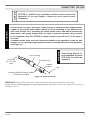
FIREPLACE DRAFT TEST
IMPORTANT: Fireplace Draft Test During Initial Installation
It is critical to verify that your chimney is drafting properly because the fireplace and gas logs function as a system.
WARNING
Although Monessen Hearth systems goes to great lengths to design vented gas log sets that minimize sooting, all
vented log sets will soot over time. Sooting normally appears as areas of black powder-like substance on the logs. It
is important to periodically clean and inspect the logs per the cleaning and servicing.
Fireplace systems that do not draft properly can increase the amount of soot produced
by normal operation of the log set and, in extreme cases, can cause soot to be deposited
within the room.This effect can be a sign of a blocked chimney, a faulty vent system or
the result of negative pressure within the home. The dealer should be able to diagnose
if a problem exists and be able to provide a solution to improve the venting of the
fireplace.
FIREPLACE DRAFT TEST METHOD
To determine if your fireplace is drafting properly, turn the log set on. After log set has been burning for about 10 minutes,
place a match or smoke stick along the top and sides of the fireplace opening. If the flame or smoke is not pulled into the
fireplace, then the fireplace is not venting properly. At this point, the damper stop should be adjusted so that the
damper opening is increased. If the problem remains after the open area of the damper is increased, then the fireplace system
should be professionally inspected to determine if your firebox/chimney is venting properly.
26
27D7300
REMOTE CONTROL RECEIVER REPLACEMENT
The remote control receiver and batteries are very sensitive to heat. Exposure to high temperatures can cause the receiver
to malfunction and shorten the life of the batteries. If your fireplace does NOT have a restrictive barrier (see page 6), such
as glass doors, it is recommended that the remote receiver be affixed to the right hand side of the heat shield or placed in
the front, right corner of the fireplace. If your fireplace has a restrictive barrier, it is recommended that the remote receiver
be placed outside of the fireplace.
WARNING
CLEANING AND SERVICING
Turn off gas logs and allow to cool
before cleaning. Disconnect electrical
power if applicable before cleaning
or servicing.
Figure 38 - Removing Soot with a Soft Bristle Brush
The log set should be cleaned at least once a year for maximum performance.
Turn gas supply off. Allow unit to cool. Remove logs, handling carefully by holding gently at each end. Gloves are recommended when handling the log to prevent skin irritation from ceramic fibers. If skin becomes irritated, wash gently with soap
and water. Refer to manual for correct log placement. Brush each log gently with a soft bristle brush. This will remove soot
that has built up on the log set. DO NOT USE LIQUID SOOT REMOVER ON LOGS!
To refurbish the grate, remove grate and take it outside. Use a wire brush or sandpaper to remove any discoloration to the
grate. Paint grate with high temperature black paint (barbecue paint). Reinstall grate after paint dries.
If embers (rock wool) have turned a rust color and become brittle, remove old embers (rock wool) from log set. Replace with
new rock wool. Rock wool can be purchased from you local dealer. See log placement section for placement of embers.
27D7300
27
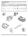
REPLACEMENT PARTS
ASSEMBLY
Item
Description
VWF(18,24,30)NM
NG
LP
MVVKN MVVKLP MXVKN MXVKLP
1
Injector
27D7022
27D7022 27D0406 27D7022 27D0406 27D7022 27D0406
2
Manual Control Valve
27D0303
27D0304 27D0304
3
Milli-volt Control Valve
—
—
—
4
Hi/Lo Remote Control Valve
—
—
—
5
Pilot
6
Shaft Extender (Manual)
(2 required)
27D0410
27D0410 27D0410
—
—
—
—
7
Control Knob
27D0417
27D0602 27D0602
—
—
—
—
—
—
—
27D0800 32D0211
—
—
—
—
27D8521 27D8522
27D0301 27D0302 27D7027 27D7028 27D7027 27D7028
2
1
2
3
4
6
5
28
7
27D7300
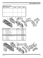
REPLACEMENT PARTS
MASSIVE OAK LOGS
Item
1
2
3
4
5
6
7
8
Description
Back Log
Left Front Log
Right Front Log
Left Side Middle Log
Right Side Middle Log
Right Top Log
Left Top Log
Top Crossover Log
18MO
24MO
30MO
27D7500
27D7501
27D7502
27D7503
27D7504
27D7505
—
—
27D7506
27D7507
27D7508
27D7503
27D7504
27D7505
27D7509
—
27D6510
27D7511
27D7512
27D7503
27D7504
27D7505
S7D7509
27D7513
#4
#2
#6
#1
#8
#5
#7
#3
Item
1
2
3
4
5
6
7
8
9
10
11
Description
Rear Log
Left Front Log
Center Front Log
Right Front Log
Left Side Log
Right Side Log
Right Side Middle Log
Top Log
Top Log
Top Log
Top Left Log
Qty
36MO
1
1
1
1
1
1
1
1
1
1
1
27D8824
27D7511
27D8825
27D7512
27D7503
27D7504
27D7509
27D8586
27D8581
27D8599
27D8826
#8
#5
#2
#7
#3
#10
#4
#6
#9
#11
#1
27D7300
29
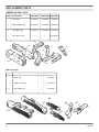
REPLACEMENT PARTS
AMERICAN OAK LOGS
Item
Description
VWF18AO VWF24AO VWF30AO
1
Front Log
27D8576
27D8584
27D8592
2
Back Log
27D8577
27D8585
27D8593
3
Right Middle Log
27D8580
27D8588
27D8596
4
Left Middle Log
27D8581
27D8589
27D8597
5
Top Right Log
27D8578
27D8586
27D8594
6
Top Left Log
27D8579
27D8587
27D8595
7
Top Center Log
—
—
27D8598
8
Top Top Center
—
—
27D8599
#4
#2
#7
#6
#8
#3
#1
#5
BIRCH LOGS
Item
Description
Qty
VWF24B
1
Back Log
1
27D1026
2
Middle Log
1
27D1025
3
Right Front Log
1
27D1024
4
Left Front Log
1
27D1023
5
Top Right Log
1
27D1028
6
Top Left Log
1
27D1027
#3
#5
#2
#1
30
#6
#4
27D7300
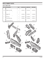
REPLACEMENT PARTS
SPLIT RIVER OAK LOGS
Item
Description
Qty
VWF24SRO
VWF30SRO
VWF36SRO
1
Back Log
1
27D8800
27D8807
27D8814
2
Bottom Left Log
1
27D8801
27D8808
27D8815
3
Bottom Right Log
1
27D8802
27D8809
27D8816
4
Top Right Log
1
27D8803
27D8810
27D8817
5
Bottom Front Left Log
1
27D8804
27D8811
27D8818
6
Top Left Log
1
27D8805
27D8812
27D8819
7
Center Top Log
1
27D8806
27D8813
27D8820
8
Front Right Log
1
—
—
27D8821
#2
#3
6#
#1
7#
#5
4#
27D7300
8#
31
REPLACEMENT PARTS
SPLIT PINE LOGS
Item
Description
Qty
VWF18SP
VWF24SP
VWF30SP
1A
Front Left Log
1
27D8700
27D8702
27D8704
1B
Right Front Log
1
27D8701
27D8703
27D8705
2
Side Support Log
1
27D8551
27D8559
27D8567
3
Rear Log
1
27D8552
27D8560
27D8568
4
Right Log
1
27D8553
27D8561
27D8569
5
Right Middle Log
1
27D8554
27D8562
27D8570
6
Left Log
1
27D8555
27D8563
27D8571
7
Top Center Log
1
27D8556
27D8564
27D8572
8
Top Left Log
1
27D8557
27D8565
27D8573
9
Top Top Left Log
1
—
—
27D8574
#8
#8
#7
#9
#7
#6
#5
#6
#4
#5
#4
#2
#2
#3
#3
#1A
#1A
#1B
32
#1B
27D7300
NOTES
27D7300
33
NOTES
34
27D7300
NOTES
27D7300
35
LIMITED LIFETIME WARRANTY POLICY
LIFETIME WARRANTY
The following components are warranted for life to the original owner, subject to proof of purchase:
Firebox, Combustion Chamber, Heat Exchanger, Grate, Stainless Steel Burners, and Vented Fiber Ceramic
and Refractory Logs.
FIVE YEAR WARRANTY
The following components are warranted for 5 years to the original owner, subject of proof of purchase:
Aluminized Burners.
BASIC WARRANTY
Monessen Hearth Systems (MHS) warrants the components and materials in your gas appliance to be free from
manufacturing and material defects for a period of two years from date of installation. After installation, if any of
the components manufactured by MHS in the appliance are found to be defective in materials or workmanship,
MHS will, at its option, replace or repair the defective components at no charge to the original owner. MHS
will also pay for reasonable labor costs incurred in replacing or repairing such components for a period of
two years from the date of installation. Any products presented for warranty repair must be accompanied
by a dated proof of purchase.
This Limited Warranty will be void if the appliance is not installed by a qualified installer in accordance with
the installation instructions. The Limited Lifetime Warranty will also be void if the appliance is not operated
and maintained according to the operating instructions supplied with the appliance, and does not extend to (1)
firebox/burner assembly damage by accident, neglect, misuse, abuse, alteration, negligence of others, including
the installation thereof by unqualified installers, (2) the costs of removal, reinstallation or transportation of
defective parts on the appliance, or (3) incidental or consequential damage. All service work must be performed
by an authorized service representative.
This warranty is expressly in lieu of other warranties, express or implied, including the warranty of mechantability
of fitness for purpose and of all other obligations or liabilities. Monessen Hearth Systems, Inc. does not
assume for it any other obligations or liability in connection with the sale or use of the appliance. In states
that do not allow limitations on how long an implied warranty lasts, or do not allow exclusion of indirect
damages, those limitations of exclusions may not apply to you. You may also have additional rights not
covered in this Limited Warranty.
MHS reserves the right to investigate any and all claims against the Limited Warranty and decide upon
method of settlement.
For information about this warranty, contact:
Technical Services
Monessen Hearth Systems
149 Cleveland Drive
Paris, Kentucky 40361
Date: June 2004
P/N 27D7300 • Rev. 4