1
DUOTHERM®
RECORD THIS INFORMATION FOR FUTURE REFERENCE
BEFORE INSTALLING THE UNIT:
by Dometic
Model Number
Serial Number
Date Purchased
Place of Purchase
Moi,a‘ Penguin®
ROOF MOUNT AIR CONDITIONER
WITH REMOTE ELECTRONIC THERMOSTAT
MODELS 610115.411 & 610115.311
USA
SERVICE OFFICE
The Dometic Corp.
509 So. Poplar St.
LaGrange, IN 46761
PATENT NO. 4641502
CANADA
Dometic Dist.
866 Langs Dr.
Cambridge, Ontario
CANADA N3H 2N7
Pre-Wired for Optional Heat Package
UNDERWRITERS
LABORATORIES
INC.
USTED
WARNING
This unit must be serviced by an
authorized serviceman. Modification of the appliance can be
extremely hazardous and could
lead to serious injury or death.
AVIS
Cet appareil dolt etre repare seulement par un reparateur autorise.
Modification de ('appareil pourrait
etre extremement dangereuse, et
pourrait causer mal ou mort.
INSTALLATION &
OPERATING INSTRUCTIONS
Form No. 3103933.010 4/92
01991,1992 The Dometic Corp.
LaGrange, IN 46761
IMPORTANT INSTRUCTIONS
MUST STAY WITH UNIT
OWNER - READ CAREFULLY
MODEL
610115.411
610115.311
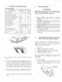
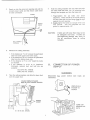
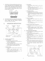
1. GENERAL INFORMATION
2. PRECAUTIONS
SPECIFICATIONS
MODEL NO.
610115.411
Nominal Capacity (BTU/HR)
13,500
Electrical Rating
WARNING
610115.311
IMPROPER INSTALLATION MAY DAMAGE EQUIPMENT, COULD ENDANGER LIFE, CAUSE SERIOUS
INJURY AND/OR PROPERTY DAMAGE.
13,500
115 VAC, 60 Hz., 1 ph.
Compressor Rated Load Amps
11.5
12.4
Fan Motor Rated Load Amps
3.1
3.1
Compressor Locked Rotor Amps
50.0
60.0
Fan Motor Locked Rotor Amps
8.8
8.8
Heater Amps @ 120V AC
12.7
12.7
Power, Cooling (kw)
1.7
1.7
Power, Heating (kw)
1.6
1.6
Refrigerant (R22) Oz.
17.0
15.5
Minimum Wire Size
12 AWG Copper Up to 24 ft.
Irk*
Circuit Protection
A.
B.
C.
20 Amp Time Delay Fuse or
D.
HACR Circuit Breaker
Installed Weight (Pounds)
114
Roof Thickness (Min./Max.) *
1' to 6'
Minimum Generator
1 Unit
3.5 KW
3.5KW
Size "
2 Units
5.0 KW
5.0KW
108
1" to 6'
E.
Read installation and operating instructions
carefully before starting your air conditioner
installation.
The Dometic Corporation will not be liable for any
damages or injury incurred due to failure in
following these instructions.
Installation must comply with the National Electrical
Code and any State or Local codes or regulations.
DO NOT add any devices or accessories to this air
conditioner except those specifically authorized by
The Dometic Corporation.
This equipment must be serviced by qualified
personnel and some states require these people to
be licensed.
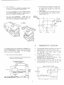
3. CHOOSING PROPER LOCATION
FOR THE AIR CONDITIONER
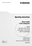
9-1/2'
This air conditioner is specifically designed for
installation on the roof of a recreational vehicle (RV).
When determining your cooling requirements, the
following should be considered:
1.
2.
3.
4.
5.
2-1/r
■
Ili\ 22"
Size of RV
Window area (increases heat gain)
Amount of insulation in walls and roof of RV.
Geographical location where RV will be used
Personal comfort level required.
From this information the size of air conditioner(s) and
the number of air conditioners needed can be
determined.
*** For lengths over 24' consult the National Electrical
Code.
A. Normal Location
The air conditioner is designed to fit over an
existing roof vent opening. When the vent is
removed, it normally creates a 14' X 14" opening.
** The Dometic Corporation gives general guidelines for
generator requirements. These guidelines come from
experience people have had in actual applications.
When sizing the generator, the total power usage must
be considered. Also keep in mind generators lose
power at high altitudes and from lack of maintenance.
ROOF VENT
OPENING
* For roofs 4-1/4' to 6' thick an optional duct (Part No.
318556) and bolt kit (Part No. 318557) are required.
This air conditioner is prewired for an Optional Electric
Heater.
2
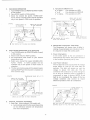
2. The roof must be designed to support 140
lbs. when the RV is in motion. Normally 220
lb. static load design will meet this
requirement.
3. Check inside the RV for air box obstructions
(i.e. door openings, room dividers, curtains,
ceiling fixtures, etc.)
B. Other Locations
When no roof vent is available or another location
is desired, the following is recommended:
For one unit installation: The air conditioner should
be mounted slightly forward of center (front to
back) and centered from side to side.
AIR BOX
PERIMETER
For two unit installations:
Install one Air
Conditioner 1/3 and one Air Conditioner 2/3's from
front of RV and centered from side to side.
1
3'
1
1
1
1
1
-4.
...S.-I 4-1/8' -4--
L - LENGTH
-•"
L
I
-1
...ide
r
l oo
14' X 14'
OPENING
CENTER UNE
OF OPENING
d.i1 ie'''
I
-±
4- 41/8r
..--0.-
+3.
1/3 L
1 ■4-- 11' .--10.-1-4....
dc>
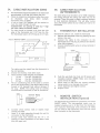
4. THERMOSTAT LOCATION
It is preferred that the air conditioner be installed in a
relatively flat and level roof section measured with the RV
parked on a level surface. NOTE: A 8 ° slant to either
side,or front to back, is acceptable.
A.
B.
C.
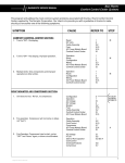
C. After location has been selected:
The thermostat should be located on an inside wall
approximately 4-1/2 feet (54') above the floor.
Check the location for heat source other than room
air. (Example: cook stove, direct sunlight,
microwave oven, or lights.)
A hole at least 7/8" diameter will be needed to
route the cable through the wall.
SUGGESTION: An opening 2' wide by 1' high
will make cable connection easier.
1. Check for obstructions in the area where air
conditioner will be installed.
D.
Air Conditioner Dimensions
(on top of vehicle)
The hole should be located 2' from the right edge
of the thermostat and 1-1/2' from the top. The
thermostat base is 6-1/4' long by 3-1/4' high.
Hole in wall for cable
7
1 1/2"
4-1/4"
'I'
I_
KEEP THESE AREAS
FREE OF OBSTRUCTIONS
[4
4
3
6 1/4"
2"
71
5A. CABLE INSTALLATION (OEM)
A.
B.
C.
5B. CABLE INSTALLATION
(AFTERMARKET)
The thermostat should be located on an inside wall
approximately 4-1/2 feet (54') above the floor.
Check the location for heat source other than room
air. (Example: cook stove, direct sunlight,
microwave oven, or lights.)
A hole at least 7/8' diameter will be needed to
route the cable through the wall.
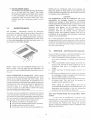
The same steps must be taken as for OEM installation
but routing through the ceiling and walls may not be
practical. There are metal or plastic raceways available
at most electrical distributors. This will allow routing
along the interior surface of your ceiling and wall to the
thermostat.
SUGGESTION: An opening 2" wide by 1" high
will make cable connection easier.
D.
The hole should be located 3-1/4' from the right
edge of the thermostat and 1-1/2" from the top.
The thermostat base is 6-1/4' long by 3-1/4' high.
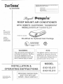
6. THERMOSTAT INSTALLATION
Now that the cable is run, install the thermostat.
A. Remove the thermostat cover by gripping top and
bottom, then pull.
B. Connect the cable to the connector on the
thermostat back. The plug is polarized and latches
when fully engaged.
C. Connect remote switch wires to screw terminals if
applicable.
Hole in Wall for Cable
0
T
1-1/2"
I
7/8" Dia. Min.
0
1-----
3-1/4"
6-1/4"
Optional ON-OFF
Remote Switch
Connection
The cable must be routed from the thermostat to
the roof opening.
E. Choose the shortest, most direct route.
F. Three standard cable lengths are available:
1.
15 feet - Part No. 3101632.010
2.
25 feet - Part No. 3101632.028
30 feet - Part No. 3101632.036
3.
G. The air conditioning end of the cable is covered
with a heat shrink tubing. This allows cable routing
through a 7/8' diameter hole without damage to
the plug. NOTE: The tubing must be carefully
removed before connection to the air conditioner.
D.
E.
F.
G.
Shrink Wrap
H.
I.
J.
Connector
Push the wire back into hole and fill excess with
insulating material. (NOTE: Make sure mounting
screw will not hit cable).
Mount base to wall with two screws provided,
being careful to not damage touch pad.
Check alignment and tighten screws.
Replace cover.
7. REMOTE SWITCH
INSTALLATION (Optional)
The thermostat has provision for connection of a remote
ON/OFF switch. The user-specified switch may be
installed anywhere up to 40 feet from the thermostat.
Two conductor thermostat wires (minimum 28 AWG)
can be used for this connection and must be routed
from the switch to the thermostat.
Consider where screws, nails or staples might
contact the cable.
Leave 3' of cable extending through the wall for
connection to the thermostat.
Enough cable must extend into the 14" x 14'
opening to allow connection to the ribbon cable
from the upper unit.
4
C. OPENING PREPARATION
1. If the opening exceeds 14-1/2' X 14-1/2', it
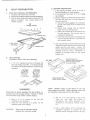
8. ROOF PREPARATION
A.
will be necessary to install spacers.
2. If the opening is less than 14' X 14', it must
be enlarged.
3. Route a copper 12 AWG with ground supply
line from the fuse box or circuit breaker to
the roof opening.
a. The power supply must be on a separate
20 amp Time Delay Fuse or HACR Circuit
Breaker.
b. Wiring must comply with all National,
State and Local wiring codes.
c. Make sure at least 20' of wire extend into
the roof opening. This insures easy air
conditioner attachment.
d. If vent fan was removed, the existing wire
may be used provided it is of proper size
and correctly fused.
ROOF VENT REMOVAL (AFTERMARKET)
1. Unscrew and remove the roof vent.
2. Remove all caulking compound around opening.
3. Seal all screw holes and seams where the roof
gasket is located. Use a good grade of all
weather sealant.
4,
1. REMOVE SCREWS
2. REMOVE VENT
• 04411
4. SEAL HOLES
AND SEAMS
4.41:P'"I
.1°Y11111111
H
211
"
444
(ROOF
SEAM)
"°'
..••■
4. The roof opening must be framed to provide
•
adequate support and prevent air from being
drawn from the roof cavity. Lumber 3/4'
thick or more and long enough to bridge the
opening must be used. Remember to
provide an entrance hole for the power
supply wire.
3. SCRAPE PUTTY
B. NEW OPENING
(Installation Other Than Vent Opening)
3/4' MIN.
r
1. A 14' X 14' opening must be cut through the
roof and ceiling of the RV. It is recommended
this opening be located between roof reinforcing
members.
NO BLOCKAGES
FRAME OPENING TO
PREVENT ROOF COLLAPSING
WHEN AIR CONDITIONER
IS BOLTED DOWN.
20' MIN.
DON'T REMOVE
STRUCTURE
LEAVE ACCESS FOR
POWER SUPPLY WIRING
NOTE: NEVER create a LOW SPOT on the roof
where water will collect. Water standing around the
air conditioner may leak Into the RV Interior.
WARNING
Disconnect all power supplies and the positive (+)
terminal from the supply battery. Failure to follow
this instruction may create a shock hazard.
5. The 14' X 14' roof opening is part of the
return air and must be finished in
accordance with NFPA Standard 501C,
Standard for recreational vehicles, Section
2-7.
2. Mark a 14' X 14' square on the roof and
carefully cut the opening.
3. Using the roof opening as a guide, cut the
matching hole in the ceiling.
CAUTION:
6. Use a steel sleeve and a grommet (or
equivalent methods) to protect the wire
where it passes through the return air duct.
There may be electrical wiring
between the roof and ceiling.
5
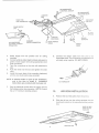
9. PLACING THE AIR
CONDITIONER ON THE ROOF
10. DISCHARGE DUCT AND CEILING
TEMPLATE INSTALLATION
A. Remove and discard the carton. The air box and
mounting parts are in a separate box located in
the carton. These parts will be used for the inside
portion of the installation.
A. Remove the air box and mounting hardware from
their carton. The upper duct is shipped inside the
lower duct which is part of the ceiling template.
The mounting hardware is in a plastic bag.
MOUNTING HARDWARE:
6
Sharp pointed sheet metal screws
3
1/4-20 X 6' Mounting Bolts
3
Wire nuts
1
Junction box cover
1
Blunt point sheet metal screw
B.
SIDE WITHOUT
TAB TO REAR
OF APPLIANCE
Place the air conditioner on the roof.
CAUTION: Use care In lifting - this unit weighs
approximately one hundred (110) pounds.
C.
Lift and place the unit over the prepared opening
using the gasket as a guide. The blunt end goes
toward the rear of the RV.
LOWER DUCT
1. Remove the upper duct from the ceiling
template and locate it over the blower
discharge. NOTE: The edge without the flange
installs toward the rear of the RV.
2. Use two of the sharp pointed sheet metal
screws to hold the duct to the base pan. The
FRONT
holes are prepunched in the pan for ease of
location.
B. Check gasket alignment over roof opening and
adjust if necessary. Unit may be moved from
below by lifting and sliding.
GASKET
CENTER NC
FROM BELOW
1
CAUTION: DO NOT slide the unit. This may
damage the neoprene gasket attached
to the bottom and create a leaky
Installation.
‘IY
\11
This completes the outside work. Minor adjustments can
be done from the inside if required.
X
6
MEASURE CEILING
THICKNESS
F. Hold the ceiling template with one hand and with
the other install the three 1/4' x 6' mounting bolts
through the template and into the base pan.
C. Reach up into the return air opening and pull the
conduit power cable and flat ribbon cable down
for later connection.
GASKET
1. Finger-tighten the (3) bolts and check
alignment. There should be an equal opening
on each side and the rear flange must be tight
against the roof opening.
2. Evenly tighten the bolts to a torque of 40 to 50
RIBBON
CABLE
This will compress the roof
inch pounds.
gasket to approximately 1/2".
CAUTION:
if bolts are left loose there may not be
an adequate roof seal. If bolts are
over-tightened damage may occur to
the air conditioner base or ceiling
template.
PULL CONDUIT
THROUGH
D. Measure the ceiling thickness:
1. If the distance is 1' to 2', remove the perforated
tabs from both upper and lower ducts.
2. If the distance is 2" to 3' remove the perforated
tabs from the bottom duct only.
3. If the distance is 3' to 4-1/4" install the ducts
as received.
4. If the distance is 4-1/4' to 6' (maximum
thickness), optional duct and bolt kits are
available:
Duct (Part No. 318556)
Bolts (Part No. 318557)
11. CONNECTION OF POWER
SUPPLY
WARNING
E. Take the ceiling template and slide the lower duct
over the upper duct.
Disconnect
connected.
ALL power before wire leads are
CEILING TEMPLATE FLANGE
MUST BE TIGHT AGAINST OPENING
UNPLUG ALL
POWER TO
COACH
RUBBER
GASKET
TURN OFF
GENERATOR
SETS
40 - 50 IN. LBS.
7
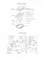
ASSEMBLY DRAWING
RFgR
AIR CONDITIONER
DISCHARGE AIR
RATING PLATE AND SERIAL NO.
NEOPRENE RUBBER GASKET
RETURN AIR
OPENING
UPPER DISCHARGE AIR DUCT
ROOF LINE
WALL THERMOSTAT CABLE
ROOF REINFORCEMENT MEMBER
14" X 14"
OPENING
POWER SUPPLY LINE
FRAMING, Return Air Duct
LOWER DISCHARGE AIR DUCT
(Attached to Ceiling Template)
UNIT
MOUNTING
BOLTS
CEILING TEMPLATE
JUNCTION BOX
MOUNTING LEGS
MOUNTING
LEGS
AIR BOX
WIRING DIAGRAM
L
LIB
AO
IA
NR
T
HEAT ACCESSORY
4
81K
I
T
1
VAYT
CRN/YEL
*4 r
3
I
WI Kal
1— 1 •
•
.
•
•
•
115 VAC 60 HZ. 10
USE COPPER CONDUCTORS ONLY
sIx
EILK
MY
L I/44T
3
YMT
atmcmr
—
FACTORY WIRING
• • •
FIELD ',SIRING
LINE SPLICE
•
3104417.005
8
AIR CONDITIONER
ELECTRICAL CONDUIT
AIR CONDITIONER
MOUNTING BOLTS
JUNCTION
BOX
DISCHARGE
AIR DUCT
TWIST TYPE
WIRE CONNECTOR
40
INHT
POWER SUPPLY
LINE
CI RN
"1"''
...001111110.VO''
V.0410
14■
14' X 14'
OPENING
i.
AIR CONDITIONER
ELECTRICAL CONDUIT
CONNECTION
A.
B.
C.
D.
E.
AUXILIARY
HEATER CONNECTION
/
JUNCTION
BOX COVER
BLUNT POINTED
SCREW
Route supply line into junction box on ceiling
tem plate.
Connect white to white; black to black; and green to
green or bare copper wire using appropriate sized
twist connectors.
Tape the connectors to the wire with electrician's
tape.
Push the wires into the box and tighten the strain
relief.
Install the cover (part of the mounting hardware)
with the one blunt point screw provided.
G.
NOTE: If optional heater is part of this installation,
now is the time to install it. Installation
instructions are provided with the heater kit.
F.
CEILING
TEMPLATE
I
RIBBON
CABLE
Connect the ribbon cable from the unit to the
thermostat cable. The connectors are polarized and
will easily snap together. DO NOT FORCE.
TO THERMOSTAT
Plug the electrical conduit from the upper unit into
the mating junction box connector. (NOTE: Conduit
has a 1.5" minimum bending radius.)
12.
AIR BOX INSTALLATION
A.
Remove the two filter-grilles from the air box.
B.
Slide the air box over the ceiling template with the
touch pad control on the same end as the junction
box.
SLIDE AIR BOX
OVER CEILING
TEMPLATE
9
JUNCTION BOX
C. Install the four (4) sharp pointed screws through the
air box legs and into the prepunched ceiling
template. NOTE: There are four optional mounting
holes on the outer edge of the return air opening for
which no screws are provided. These are only
required where an uneven ceiling does not allow
proper fitting of the air box.
CEIUNO TEMPLATE
3. Fan Switch:
a. Four position switch located on left side of
control.
b. Used to select HIGH, MEDIUM, LOW or
AUTOMATIC FAN operation.
c. Fan speed selected is indicated green LED
light when control is turned on.
AIR BOX
4. Temperature Slide:
a. Located top center of control.
b. Movable arm on control selects temperature
at which the refrigerant compressor or electric
heater (if so equipped) is turned ON and
OFF.
c. User sets to position to maintain temperature
level desired.
IMVIIPARIM AIMUNW
11111P 1111111 111111111114111
5. Low Power Light:
D.
E.
13.
a. Red indicator light located lower center of
control.
b. When on, it indicates AC voltage is below 97
volts AC.
c. Unit continues to operate (see Special
Control Features E.4)
Install the filter-grilles by pushing them into place.
Turn on power to the air conditioner for operational
check. Please read the following Operating
Instructions before proceeding.
OPERATING INSTRUCTIONS
6. Remote Power Switch Connection:
FAN LED'S
(Green)
TEMPERATURE
CONTROL
SLIDE
a. Two screw terminals located on back side of
control.
b. Used to connect a remote ON/OFF switch.
c. Remote ON/OFF switch, if used, operates
same as power switch. (See Special Control
Features E.5)
MODE LED'S
(Green)
MODE SWITCH
B. COOLING MODE OPERATION
11 . i
RIBBON CABLE
CONNECTION ON
REVERSE SIDE
POWER
SWITCH
1. Turn POWER switch (or REMOTE switch if used)
to ON position.
2. Place mode switch COOL position.
3. Set temperature slide switch to your desired
temperature level.
4. Select your desired fan speed. NOTE: See
Special Features Section E.1 for AUTO Fan
Operation.
5. The fan starts immediately and after a delay of
approximately two minutes, the compressor will
start.
6. The fan and compressor will now cycle OFF per
the set point. The fan will restart immediately and
the compressor will restart in approximately two
minutes when thermostat senses need for
cooling.
"-/N
.
REMOTE ON/OFF SWITCH
CONNECTION ON REVERSE SIDE
A. CONTROL DESCRIPTION:
1. Power Switch:
a. Located lower center of control.
b. Turns air conditioner ON to set condition of
FAN and MODE switch.
c. Turns air conditioner OFF.
d. Green LED lights next to FAN and MODE
switch light up to indicate power ON.
e. No LED lights on when control is OFF.
EXAMPLE
GREEN LED ON
NEXT TO COO
INDICATOR
TEMPERATURE SLIDE SET AT 70°
2. Mode Switch:
a. Three position switch located on right side of
control.
b. Used to select COOLING, FAN or HEAT
mode of air conditioner operation.
c. Mode selected is indicated by green LED
light when control is turned on.
DUO- THEW
0 1.0v/
1HEF
C
60
70
MED
•
El r our
80
CV..
FAU C)
POWER
/
Ili)
0
.T.
0 AUTO
LO
GREEN LED
ON NEXT TO
MED FAN
INDICATOR
FAN SWITCH SET TO
MEDIUM FAN POSITION
10
OST A T
0
R
POWER
SWITCH
IN ON
POSITION
MODE SWITCH SET
TO COOL POSITION
b. Temperature difference of:
8° or more - Fan operates on HIGH
- Fan operates on MEDIUM
4° to 8°
4° or below - Fan operates on LOW
C. FAN MODE OPERATION
1. Turn POWER switch (or REMOTE switch if used)
to ON position.
2. Place MODE switch in FAN position.
3. Select the desired fan speed: HI-MED-LOWAUTO. NOTE: In AUTO position the fan operates
only at low speed in FAN mode of operation.
GREEN LED ON NEXT
TO COOL INDICATOR
EXAMPLE
TEMPERATURE SLIDE SET AT 75
EXAMPLE
POWER SWITCH IN
ON POSITION
bY pC LUC
RIO-THERM
GREEN LED ON NEXT
TO FAN INDICATOR
0 Lo w
0 WO
60
Cot •
60
70
C)
POKR
HEAT C)
0 H
TD WSW
OOL
0 .,E0
rAN
AUTO
AUTO
BY 00u DC
LOW
POWER
SWITCH
IN ON
POSITION
GREEN LED
ON NEXT
TO AUTO FAN
INDICATOR
LOw OPOwER
GREEN LED
ON NEXT
TO HIGH FAN
INDICATOR
R
LOwC,
MODE SW TCH SET
TO COOL POSITION
FAN SWITCH SET TO AUTOMAT1C FAN POSITION
MODE SWITCH SET
TO FAN POSITION
I
FAN SWITCH SET TO HIGH FAN POSITION
2. Refrigerant Compressor Time Delay:
The compressor will always have a delay in
starting of approximately two minutes any time
it is required to begin the cooling cycle.
D. HEAT MODE OPERATION (If So Equipped)
1. Turn POWER switch (or REMOTE switch if used)
to ON position.
2. Place mode switch in HEAT position.
3. Set temperature slide switch to your desired
temperature level.
4. Select your desired fan speed (HI-MED-LOWAUTO) NOTE: In AUTO position the fan
operates only at low speed in HEAT mode of
operation.
5. The fan runs continuously with the electric heater
cycling ON/OFF per the set point to maintain an
even comfort range.
EXAMPLE
3. Power Interruption:
In the event power to the air conditioner is
interrupted for any reason, the system will restart
in the condition previously set by user.
4. Low Power Indicator:
The red light will come on any time AC voltage
drops below 97 volts AC for more than ten
seconds. The light will remain on until the
voltage is above 103 volts AC. The air
conditioner will continue to run when red light is
on as long as sufficient power is available to
compressor to keep it running. NOTE: If red
TEMPERATURE SLIDE SET AT 77°
GREEN LED ON NEXT
TO LOW FAN POSITION
light is on, investigate the cause of the low
voltage condition and correct to insure
efficient operation of the air conditioner.
POWER SWITCH INON POSITION
EXAMPLE
POWER SWITCH INON POSITION
THCPuOSTAT
DUO-THERM
FAN SWITCH
IN LOW FAN
POSITION
• LOT
MODE SWITCH SET
TO HEAT POSITION
0 UE0
60
70
BY OCwETC
60
PO
E.
C) ABM
FAN SWITCH
IN LOW FAN
POSITION
SPECIAL CONTROL FEATURES:
1. Auto Fan: When selected, FAN switch will:
r An 0
NEAT 0
Ow
GREEN LED ON NEXT TO HEAT INDICATOR
COOL •
LOw 0 wO*C P
MODE SWITCH SET
TO COOL POSITION
RED LED LIGHT ON INDICATING VOLTAGE HAS
DROPPED BELOW 97 VAC FOR MORE THAN 10 SECONDS
a. Automatically select the fan speed depending
on the difference between set temperature
and room temperature.
11
5. Remote ON/OFF Switch:
Starting the air conditioner early in the morning and
giving the system a "head start" on the expected high
outdoor ambient will greatly improve its ability to maintain
the desired indoor temperature.
This switch is user supplied and may be installed
up to 40 feet from the control. Two screw
terminals are located on the back of the control
for this connection. The remote switch acts in
conjunction with the power switch and when
installed acts like a three-way switch in your
house.
14.
CAUTION
The manufacturer of this air conditioner will not be
responsible for damage caused by condensed
moisture on ceilings or other surfaces. Air contains
moisture and this moisture tends to condense on cold
surfaces. When air enters the vehicle, condensed
moisture may appear on air registers, ceilings,
windows, etc. The air conditioner removes this
moisture from the air during normal operation.
Keeping doors and windows closed when this air
conditioner is in operation will minimize condensed
moisture on cold surfaces.
MAINTENANCE
Periodically remove the filter/grille
assemblies located in the air box and clean. Remove the
assemblies by placing fingers on the long portion of
latches and with an over-and-downward pressure,
unlatch the catches. After assemblies are removed, wash
the filter/grille assemblies with soap and warm water. Let
assemblies dry and then reinstall.
AIR FILTERS:
For a more permanent solution to a high heat gain,
accessories like A&E outdoor patio and window awnings
will reduce the heat gain by removing the direct exposure
to the sun, and add a nice area to enjoy company during
the cool of the evening.
15. SERVICE - Unit Does Not Operate
If your unit fails to operate or operates improperly, check
the following before calling your service center:
A. If RV is connected to motor generator, check to be
sure motor generator is running and producing
power.
B. If RV is connected to power supply by a land line,
check to be sure line is sized properly to run air
conditioner load and it is plugged into power
supply.
C. Check your fuse or circuit breaker to see if it is
open.
D.
In the air conditioner air box, check to be sure the
air conditioner conduit is plugged into the junction
box and ribbon cable is connected.
E. After the above checks, call your local service center
for further help. This unit must be serviced by
qualified service personnel only.
NOTE: Never run the air conditioner without return air
filters in place. This may plug the unit evaporator coil
with dirt and may substantially affect the performance of
the unit.
FROST FORMATION on Cooling Coil: Under certain
conditions, frost may form on the evaporator coil. If this
should occur, inspect the filter and clean if dirty. Make
sure air louvers are not obstructed. Air conditioners have
a greater tendency to frost when the outside temperature
is relatively low. This may be prevented by adjusting the
thermostat slide to a warmer setting. Should frost
continue, operate on LOW, MED or HIGH FAN setting
until the cooling coil is free of frost.
When calling for service always give the air
conditioner Model Number and Serial Number. This
information can be found on the unit rating plate
located on the air conditioner base pan.
The ability of the air conditioner to maintain the desired
inside temperature depends not only on the heat gain of
the vehicle but also some preventative measures taken
by the occupants. During extreme outdoor temperatures,
the heat gain of the vehicle may be reduced by:
■ Parking the vehicle in a shaded area;
■ Using window shades (blinds and/or curtains);
■ Keeping windows and door shut;
■ Avoiding the use of heat producing appliances.
DID YOU PURCHASE AN ELECTRIC HEAT
STRIP
. . . for your new air conditioner? It's simple to add
because your unit is completely pre-wired. You won't
regret adding it to remove the chill from the air on those
cool morning and eyeing hours during the camping
season. Contact your Dealer to order our 5600 BTU Heat
Strip (Part # 3101121).
12